EP3946794B1 - Stencil device and method for stencil printing of brazing material onto a heat exchanger plate and use thereof - Google Patents
Stencil device and method for stencil printing of brazing material onto a heat exchanger plate and use thereof Download PDFInfo
- Publication number
- EP3946794B1 EP3946794B1 EP20718849.1A EP20718849A EP3946794B1 EP 3946794 B1 EP3946794 B1 EP 3946794B1 EP 20718849 A EP20718849 A EP 20718849A EP 3946794 B1 EP3946794 B1 EP 3946794B1
- Authority
- EP
- European Patent Office
- Prior art keywords
- stencil
- heat exchanger
- brazing material
- exchanger plate
- openings
- Prior art date
- Legal status (The legal status is an assumption and is not a legal conclusion. Google has not performed a legal analysis and makes no representation as to the accuracy of the status listed.)
- Active
Links
Images

Classifications
-
- B—PERFORMING OPERATIONS; TRANSPORTING
- B23—MACHINE TOOLS; METAL-WORKING NOT OTHERWISE PROVIDED FOR
- B23K—SOLDERING OR UNSOLDERING; WELDING; CLADDING OR PLATING BY SOLDERING OR WELDING; CUTTING BY APPLYING HEAT LOCALLY, e.g. FLAME CUTTING; WORKING BY LASER BEAM
- B23K3/00—Tools, devices or special appurtenances for soldering, e.g. brazing, or unsoldering, not specially adapted for particular methods
- B23K3/06—Solder feeding devices; Solder melting pans
- B23K3/0607—Solder feeding devices
-
- B—PERFORMING OPERATIONS; TRANSPORTING
- B23—MACHINE TOOLS; METAL-WORKING NOT OTHERWISE PROVIDED FOR
- B23K—SOLDERING OR UNSOLDERING; WELDING; CLADDING OR PLATING BY SOLDERING OR WELDING; CUTTING BY APPLYING HEAT LOCALLY, e.g. FLAME CUTTING; WORKING BY LASER BEAM
- B23K1/00—Soldering, e.g. brazing, or unsoldering
- B23K1/0008—Soldering, e.g. brazing, or unsoldering specially adapted for particular articles or work
- B23K1/0012—Brazing of heat exchangers
-
- B—PERFORMING OPERATIONS; TRANSPORTING
- B23—MACHINE TOOLS; METAL-WORKING NOT OTHERWISE PROVIDED FOR
- B23K—SOLDERING OR UNSOLDERING; WELDING; CLADDING OR PLATING BY SOLDERING OR WELDING; CUTTING BY APPLYING HEAT LOCALLY, e.g. FLAME CUTTING; WORKING BY LASER BEAM
- B23K1/00—Soldering, e.g. brazing, or unsoldering
- B23K1/20—Preliminary treatment of work or areas to be soldered, e.g. in respect of a galvanic coating
-
- B—PERFORMING OPERATIONS; TRANSPORTING
- B23—MACHINE TOOLS; METAL-WORKING NOT OTHERWISE PROVIDED FOR
- B23K—SOLDERING OR UNSOLDERING; WELDING; CLADDING OR PLATING BY SOLDERING OR WELDING; CUTTING BY APPLYING HEAT LOCALLY, e.g. FLAME CUTTING; WORKING BY LASER BEAM
- B23K3/00—Tools, devices or special appurtenances for soldering, e.g. brazing, or unsoldering, not specially adapted for particular methods
- B23K3/06—Solder feeding devices; Solder melting pans
- B23K3/0607—Solder feeding devices
- B23K3/0638—Solder feeding devices for viscous material feeding, e.g. solder paste feeding
-
- B—PERFORMING OPERATIONS; TRANSPORTING
- B23—MACHINE TOOLS; METAL-WORKING NOT OTHERWISE PROVIDED FOR
- B23K—SOLDERING OR UNSOLDERING; WELDING; CLADDING OR PLATING BY SOLDERING OR WELDING; CUTTING BY APPLYING HEAT LOCALLY, e.g. FLAME CUTTING; WORKING BY LASER BEAM
- B23K3/00—Tools, devices or special appurtenances for soldering, e.g. brazing, or unsoldering, not specially adapted for particular methods
- B23K3/08—Auxiliary devices therefor
-
- B—PERFORMING OPERATIONS; TRANSPORTING
- B23—MACHINE TOOLS; METAL-WORKING NOT OTHERWISE PROVIDED FOR
- B23K—SOLDERING OR UNSOLDERING; WELDING; CLADDING OR PLATING BY SOLDERING OR WELDING; CUTTING BY APPLYING HEAT LOCALLY, e.g. FLAME CUTTING; WORKING BY LASER BEAM
- B23K3/00—Tools, devices or special appurtenances for soldering, e.g. brazing, or unsoldering, not specially adapted for particular methods
- B23K3/08—Auxiliary devices therefor
- B23K3/082—Flux dispensers; Apparatus for applying flux
-
- B—PERFORMING OPERATIONS; TRANSPORTING
- B23—MACHINE TOOLS; METAL-WORKING NOT OTHERWISE PROVIDED FOR
- B23K—SOLDERING OR UNSOLDERING; WELDING; CLADDING OR PLATING BY SOLDERING OR WELDING; CUTTING BY APPLYING HEAT LOCALLY, e.g. FLAME CUTTING; WORKING BY LASER BEAM
- B23K37/00—Auxiliary devices or processes, not specially adapted for a procedure covered by only one of the other main groups of this subclass
- B23K37/04—Auxiliary devices or processes, not specially adapted for a procedure covered by only one of the other main groups of this subclass for holding or positioning work
-
- B—PERFORMING OPERATIONS; TRANSPORTING
- B23—MACHINE TOOLS; METAL-WORKING NOT OTHERWISE PROVIDED FOR
- B23K—SOLDERING OR UNSOLDERING; WELDING; CLADDING OR PLATING BY SOLDERING OR WELDING; CUTTING BY APPLYING HEAT LOCALLY, e.g. FLAME CUTTING; WORKING BY LASER BEAM
- B23K37/00—Auxiliary devices or processes, not specially adapted for a procedure covered by only one of the other main groups of this subclass
- B23K37/04—Auxiliary devices or processes, not specially adapted for a procedure covered by only one of the other main groups of this subclass for holding or positioning work
- B23K37/0408—Auxiliary devices or processes, not specially adapted for a procedure covered by only one of the other main groups of this subclass for holding or positioning work for planar work
-
- B—PERFORMING OPERATIONS; TRANSPORTING
- B23—MACHINE TOOLS; METAL-WORKING NOT OTHERWISE PROVIDED FOR
- B23K—SOLDERING OR UNSOLDERING; WELDING; CLADDING OR PLATING BY SOLDERING OR WELDING; CUTTING BY APPLYING HEAT LOCALLY, e.g. FLAME CUTTING; WORKING BY LASER BEAM
- B23K37/00—Auxiliary devices or processes, not specially adapted for a procedure covered by only one of the other main groups of this subclass
- B23K37/06—Auxiliary devices or processes, not specially adapted for a procedure covered by only one of the other main groups of this subclass for positioning the molten material, e.g. confining it to a desired area
-
- F—MECHANICAL ENGINEERING; LIGHTING; HEATING; WEAPONS; BLASTING
- F28—HEAT EXCHANGE IN GENERAL
- F28D—HEAT-EXCHANGE APPARATUS, NOT PROVIDED FOR IN ANOTHER SUBCLASS, IN WHICH THE HEAT-EXCHANGE MEDIA DO NOT COME INTO DIRECT CONTACT
- F28D9/00—Heat-exchange apparatus having stationary plate-like or laminated conduit assemblies for both heat-exchange media, the media being in contact with different sides of a conduit wall
- F28D9/0031—Heat-exchange apparatus having stationary plate-like or laminated conduit assemblies for both heat-exchange media, the media being in contact with different sides of a conduit wall the conduits for one heat-exchange medium being formed by paired plates touching each other
- F28D9/0043—Heat-exchange apparatus having stationary plate-like or laminated conduit assemblies for both heat-exchange media, the media being in contact with different sides of a conduit wall the conduits for one heat-exchange medium being formed by paired plates touching each other the plates having openings therein for circulation of at least one heat-exchange medium from one conduit to another
- F28D9/005—Heat-exchange apparatus having stationary plate-like or laminated conduit assemblies for both heat-exchange media, the media being in contact with different sides of a conduit wall the conduits for one heat-exchange medium being formed by paired plates touching each other the plates having openings therein for circulation of at least one heat-exchange medium from one conduit to another the plates having openings therein for both heat-exchange media
-
- F—MECHANICAL ENGINEERING; LIGHTING; HEATING; WEAPONS; BLASTING
- F28—HEAT EXCHANGE IN GENERAL
- F28F—DETAILS OF HEAT-EXCHANGE AND HEAT-TRANSFER APPARATUS, OF GENERAL APPLICATION
- F28F3/00—Plate-like or laminated elements; Assemblies of plate-like or laminated elements
- F28F3/02—Elements or assemblies thereof with means for increasing heat-transfer area, e.g. with fins, with recesses, with corrugations
-
- F—MECHANICAL ENGINEERING; LIGHTING; HEATING; WEAPONS; BLASTING
- F28—HEAT EXCHANGE IN GENERAL
- F28F—DETAILS OF HEAT-EXCHANGE AND HEAT-TRANSFER APPARATUS, OF GENERAL APPLICATION
- F28F3/00—Plate-like or laminated elements; Assemblies of plate-like or laminated elements
- F28F3/02—Elements or assemblies thereof with means for increasing heat-transfer area, e.g. with fins, with recesses, with corrugations
- F28F3/04—Elements or assemblies thereof with means for increasing heat-transfer area, e.g. with fins, with recesses, with corrugations the means being integral with the element
- F28F3/042—Elements or assemblies thereof with means for increasing heat-transfer area, e.g. with fins, with recesses, with corrugations the means being integral with the element in the form of local deformations of the element
-
- F—MECHANICAL ENGINEERING; LIGHTING; HEATING; WEAPONS; BLASTING
- F28—HEAT EXCHANGE IN GENERAL
- F28F—DETAILS OF HEAT-EXCHANGE AND HEAT-TRANSFER APPARATUS, OF GENERAL APPLICATION
- F28F3/00—Plate-like or laminated elements; Assemblies of plate-like or laminated elements
- F28F3/02—Elements or assemblies thereof with means for increasing heat-transfer area, e.g. with fins, with recesses, with corrugations
- F28F3/04—Elements or assemblies thereof with means for increasing heat-transfer area, e.g. with fins, with recesses, with corrugations the means being integral with the element
- F28F3/042—Elements or assemblies thereof with means for increasing heat-transfer area, e.g. with fins, with recesses, with corrugations the means being integral with the element in the form of local deformations of the element
- F28F3/046—Elements or assemblies thereof with means for increasing heat-transfer area, e.g. with fins, with recesses, with corrugations the means being integral with the element in the form of local deformations of the element the deformations being linear, e.g. corrugations
-
- F—MECHANICAL ENGINEERING; LIGHTING; HEATING; WEAPONS; BLASTING
- F28—HEAT EXCHANGE IN GENERAL
- F28F—DETAILS OF HEAT-EXCHANGE AND HEAT-TRANSFER APPARATUS, OF GENERAL APPLICATION
- F28F3/00—Plate-like or laminated elements; Assemblies of plate-like or laminated elements
- F28F3/08—Elements constructed for building-up into stacks, e.g. capable of being taken apart for cleaning
- F28F3/10—Arrangements for sealing the margins
-
- B—PERFORMING OPERATIONS; TRANSPORTING
- B23—MACHINE TOOLS; METAL-WORKING NOT OTHERWISE PROVIDED FOR
- B23K—SOLDERING OR UNSOLDERING; WELDING; CLADDING OR PLATING BY SOLDERING OR WELDING; CUTTING BY APPLYING HEAT LOCALLY, e.g. FLAME CUTTING; WORKING BY LASER BEAM
- B23K2101/00—Articles made by soldering, welding or cutting
- B23K2101/04—Tubular or hollow articles
- B23K2101/14—Heat exchangers
-
- B—PERFORMING OPERATIONS; TRANSPORTING
- B23—MACHINE TOOLS; METAL-WORKING NOT OTHERWISE PROVIDED FOR
- B23K—SOLDERING OR UNSOLDERING; WELDING; CLADDING OR PLATING BY SOLDERING OR WELDING; CUTTING BY APPLYING HEAT LOCALLY, e.g. FLAME CUTTING; WORKING BY LASER BEAM
- B23K2103/00—Materials to be soldered, welded or cut
- B23K2103/02—Iron or ferrous alloys
-
- B—PERFORMING OPERATIONS; TRANSPORTING
- B23—MACHINE TOOLS; METAL-WORKING NOT OTHERWISE PROVIDED FOR
- B23K—SOLDERING OR UNSOLDERING; WELDING; CLADDING OR PLATING BY SOLDERING OR WELDING; CUTTING BY APPLYING HEAT LOCALLY, e.g. FLAME CUTTING; WORKING BY LASER BEAM
- B23K2103/00—Materials to be soldered, welded or cut
- B23K2103/02—Iron or ferrous alloys
- B23K2103/04—Steel or steel alloys
- B23K2103/05—Stainless steel
-
- F—MECHANICAL ENGINEERING; LIGHTING; HEATING; WEAPONS; BLASTING
- F28—HEAT EXCHANGE IN GENERAL
- F28F—DETAILS OF HEAT-EXCHANGE AND HEAT-TRANSFER APPARATUS, OF GENERAL APPLICATION
- F28F2275/00—Fastening; Joining
- F28F2275/04—Fastening; Joining by brazing
-
- F—MECHANICAL ENGINEERING; LIGHTING; HEATING; WEAPONS; BLASTING
- F28—HEAT EXCHANGE IN GENERAL
- F28F—DETAILS OF HEAT-EXCHANGE AND HEAT-TRANSFER APPARATUS, OF GENERAL APPLICATION
- F28F2275/00—Fastening; Joining
- F28F2275/04—Fastening; Joining by brazing
- F28F2275/045—Fastening; Joining by brazing with particular processing steps, e.g. by allowing displacement of parts during brazing or by using a reservoir for storing brazing material
-
- F—MECHANICAL ENGINEERING; LIGHTING; HEATING; WEAPONS; BLASTING
- F28—HEAT EXCHANGE IN GENERAL
- F28F—DETAILS OF HEAT-EXCHANGE AND HEAT-TRANSFER APPARATUS, OF GENERAL APPLICATION
- F28F3/00—Plate-like or laminated elements; Assemblies of plate-like or laminated elements
- F28F3/02—Elements or assemblies thereof with means for increasing heat-transfer area, e.g. with fins, with recesses, with corrugations
- F28F3/04—Elements or assemblies thereof with means for increasing heat-transfer area, e.g. with fins, with recesses, with corrugations the means being integral with the element
- F28F3/042—Elements or assemblies thereof with means for increasing heat-transfer area, e.g. with fins, with recesses, with corrugations the means being integral with the element in the form of local deformations of the element
- F28F3/044—Elements or assemblies thereof with means for increasing heat-transfer area, e.g. with fins, with recesses, with corrugations the means being integral with the element in the form of local deformations of the element the deformations being pontual, e.g. dimples
Definitions
- the present invention relates to a stencil device according to the preamble of claim 1 (see for example JP 2014 185803 A ), for simultaneous stencil printing of brazing material onto ridges, areas surrounding port openings, and a circumferential skirt of a heat exchanger plate.
- the present invention also relates to the use of such a device and to a method for printing of brazing material onto a heat exchanger plate, see respectively claims 13 and 14.
- Brazed plate heat exchangers are generally manufactured from plates made from sheet metal that has been provided with a pressed pattern of ridges and grooves adapted to keep the plates on a distance from one another such that interplate flow channels for media to exchange heat are formed between the plates. In order to keep the plates together, they are brazed to one another in the contact points between the ridges and grooves of neighbouring plates. Port openings are provided - often near corners of the heat exchanger plates - and areas surrounding the port openings are provided on different heights such that selective fluid communication between the port openings and the interplate flow channels is achieved.
- the circumferential seal is provided by skirts extending along the circumference of each plate, wherein skirts extend in a plane close to perpendicular to the plane of the heat exchanger plate and are adapted to overlappingly contact one another, hence providing for the circumferential seal.
- brazing material When manufacturing brazed heat exchangers, it is necessary to provide a brazing material to the surface that are supposed to be brazed together, i.e. in many cases, such brazing material is provided by arranging a foil of brazing material (e.g. copper or nickel if the heat exchanger plates are made from stainless steel) between the heat exchanger plates.
- a foil of brazing material e.g. copper or nickel if the heat exchanger plates are made from stainless steel
- the base material i.e. the material from which the heat exchanger plates are manufactured
- the brazing material for example if an iron based brazing material containing melting point depressants is used for brazing heat exchanger plates made from stainless steel
- providing the brazing material in form of a foil has many disadvantages.
- the present invention solves the above and other problems by providing a stencil device for simultaneous stencil printing of brazing material onto elevations, areas surrounding port openings, and a circumferential skirt of a heat exchanger plate as defined in claim 1, wherein the stencil device comprises an upper stencil having openings for applying brazing material to the elevations and areas surrounding port openings of the heat exchanger plate and a lower printing stencil having a large opening for receiving a heat exchanger plate and contacting an outer perimeter of the circumferential skirt of the heat exchanger plate, wherein an inner surface of the large opening comprises brazing material exits for applying brazing material to the circumferential skirts.
- canals may be arranged between circumferential openings of the upper stencil and the brazing material exits such that brazing material will be pressed from the circumferential openings through the canals to the brazing material exits.
- the upper stencil may be manufactured from sheet metal, rubber, plastic, fabric or the like.
- openings of the upper stencil may be placed in pairs, wherein each opening of each pair is placed such that it will be located close to, but not at, a contact point between an elevation and a depression of neighboring heat exchanger plates.
- the lower stencil printing stencil may be made from a dense material, e.g. plastic or metal, that has a thickness exceeding a height of a circumferential skirt of a heat exchanger plate.
- the inner surface of the lower stencil printing stencil may be covered with a resilient material in order to avoid leakage of brazing materiel between said inner surface and an outer surface of a circumferential skirt of the heat exchanger plate to be applied with brazing material.
- the resilient material may be inflatable to secure a tight fit to the outer surface of the circumferential skirt.
- the elevations may be in the form of ridges adapted to form contacts with grooves of a neighboring plate when heat exchanger plates are stacked on top of one another.
- the brazing material can be conveyed to the brazing material exits by canals arranged between circumferential openings of the upper stencil and the brazing material exits.
- stencil printing is a technology wherein a stencil is provided between an article to be printed and an applicator of the printing material. Openings are provided in the stencil, such that the printing material will be applied to the article to be printed where the holes are provided.
- the invention is intended to provide a method and a device for applying brazing material to a heat exchanger plate to be comprised in a brazed heat exchanger.
- Brazed heat exchangers are well known by persons skilled in the art and comprise a multitude of heat exchanger plates provided with a pressed pattern of ridges and grooves adapted to contact ridges and grooves of neighboring plates such that the heat exchanger plates are kept on a distance from one another under formation of interplate flow channels for media to exchange heat.
- the interplate flow channels are in selective fluid communication with port openings provided in each heat exchanger plate, wherein the selectivity is provided by arranging areas surrounding the port openings on different heights, such that there will be a communication between the port opening and the interplate flow channel if the areas surrounding the port openings of neighbouring heat exchanger plates do not contact one another and such that no communication between port opening and the interplate flow channel will occur when the areas surrounding the port openings of neighbouring heat exchanger plates do contact one another.
- a circumferentially extending skirt is provided on each heat exchanger plate, wherein the skirts of neighboring heat exchanger plates are arranged to overlappingly contact one another such that the interplate flow channels are sealed from leakage around the circumference of the heat exchanger plate.
- a stencil 100 for stencil printing brazing material onto a heat exchanger plate is shown.
- the stencil 100 is based on a flat base material 110, which e.g. may be manufactured from sheet metal, rubber, plastic, fabric or the like.
- the stencil 100 is provided with openings 120 for applying brazing material to contact points between ridges and grooves of neighboring heat exchanger plates.
- the ridges and grooves just as well may be shaped in other shapes than ridges and grooves, e.g. as elevated dots adapted to form contact points between neighboring plates.
- the openings 120 are placed in pairs, wherein each opening of each pair is placed such that it will be located close to, but not at, a contact point between a ridge and a groove of neighboring heat exchanger plates. In other embodiments of the invention, the openings are not placed in such pairs, but are located at the contact point between ridges and grooves of neighboring heat exchanger plates.
- ring-shaped openings 130 for applying brazing material to areas surrounding port openings of the heat exchanger plate to be printed.
- inner portions of the ring-shaped openings are not open - rather, there is a stencil portion held in place within each of the ring-shaped openings 130 by means of bridges 135. This central stencil portion will hinder excessive amounts of brazing material to be applied to the areas surrounding the port openings.
- the bridges 135 may lead to a leaking braze connection of the areas surrounding the port openings, but such leakage may be reduced by providing dual ring-shaped openings 130 around each port opening, wherein the bridges 135 are angularly offset with respect to one another.
- the stencil 100 is provided with circumferential openings 140.
- the circumferential openings 140 are placed outside a circumference of a heat exchanger plate to be provided with brazing material, and their function will be described with reference to Figs. 2a and 2b .
- spokes 145 extend from an area outside the circumferential openings 140 and the stencil portion comprising the openings 120 and the ring-shaped openings 130.
- FIGs 2a and 2b section views of a stencil device including a lower stencil printing stencil 150 is shown.
- the stencil device comprises the stencil 100 and the lower stencil printing stencil 150, wherein the stencil 100 is an upper stencil.
- the lower stencil printing stencil 150 is made from a dense material, e.g. plastic or metal, and has a thickness T exceeding a height of a circumferential skirt 210 of a heat exchanger plate 200.
- the lower stencil printing stencil comprises a large opening 190, an inner surface 195 of which being arranged to closely contact an outer surface of the circumferential skirt 210 of the heat exchanger plate 200.
- the inner surface 195 is provided with a number of brazing material exits 180, which are in fluid communication with mouths 170 by canals 160.
- the brazing material exits, the canals and the mouths are placed such that they mate with the circumferential openings 140 of the stencil 100.
- a heat exchanger plate 200 to be brazed is placed in the large opening 190, and the device is pressed together such that the inner surface 195 closely will fit to the outer surface of the circumferential skirt 210 of the heat exchanger plate and such that the stencil 100 will be in close contact with ridges R and areas surrounding the port openings of the heat exchanger plate 200 to be stencil printed with brazing material.
- a brazing material paste is applied to the side of the stencil that is not engaging the heat exchanger plate 200, preferably by pushing a "sausage" like string of brazing material over the stencil 100.
- brazing material will be pushed through the openings 120 and hence provide brazing material at or close to the contact points between ridges and grooves of neighboring heat exchanger plates, through the ring-shaped openings 130 to provide brazing material to the area surrounding the port openings and through the circumferential openings 140.
- the brazing material that is pushed through the circumferential openings 140 will enter the mouths 170, which are fluidly connected to the brazing material exits 180 via the canals 160 and hence, the outer surface of the circumferential skirt 210 will be provided with brazing material.
- the stencil 100 and the lower stencil printing stencil is carefully removed from the heat exchanger plate and the heat exchanger plates are placed in a stack with other heat exchanger plates in order to form a heat exchanger plate pack to be brazed to a heat exchanger.
- the inner surface 195 may be coated with a resilient material, e.g. rubber or the like. It may also be advantageous if the resilient material is inflatable by liquid or gas, such that the heat exchanger plate 200 may be placed in and taken away from the large opening 190 without contacting its inner surface 195, while contact may be established by inflating the resilient material during the brazing operation and deflating it after the brazing operation.
- a resilient material e.g. rubber or the like.
- the heat exchanger plate 200 is held in place by an elevated portion (not shown) of a tray (not shown) adapted to host the heat exchanger plates to be printed.
- the tray may comprise one or more such elevated portions, depending on the number of heat exchanger plates that are supposed to be printed simultaneously.
- the elevated portions have an outer perimeter corresponding to an inner perimeter of the circumferential skirt 210 of the heat exchanger plate 200, such that the heat exchanger plate is held in place during the stencil printing operation.
- An upper surface of the elevated portion is designed to provide support for the areas surrounding the port openings of the heat exchanger plate and the ridges and/or grooves that are to be stencil printed.
- the heat exchanger plate(s) is (are) placed on the tray such that the elevated portion keeps the heat exchanger plate in place. This is sufficient for the stencil printing operation. However, depending on the rheological properties of the brazing material, it might be necessary to lock the heat exchanger plate onto the elevated portion once the stencil printing operation is finished and the upper and lower stencils are removed from contact with the heat exchanger plate. This may be achieved in several ways, of which two deserve to be mentioned:
- the stencil device and stencil printing method according to the present invention is intended to provide brazing material to areas at or neighboring contact points between heat exchanger plates to be joined by brazing.
- the brazing material is preferably provided in the form of a paste having a rheological property resembling the properties of peanut butter.
- the brazing material paste comprises grains of brazing material, i.e. grains of a metal or an alloy having a melting point lower than the material from which the heat exchanger plates are manufactured, a solvent that may vaporize after the brazing material has been applied to the heat exchanger plate and a binder that keeps the brazing material grains at place after the solvent has evaporated.
- the binder must have sufficient heat resistance to keep the brazing material together until the brazing material has melted.
- brazing material paste must have excellent adhesive properties in order to adhere properly to the skirts.
- brazing paste comprising powder brazing material alloy with a grain size of less than 106 Microns, dispersed in a paste having a metal content of 92 ⁇ 1 wt-%, the remainder binder and solvent.
- the Brookfield viscosity of the paste at 21 °C, TD-spindle 2.5 rpm 450 ⁇ 50 Pas.
Landscapes
- Engineering & Computer Science (AREA)
- Mechanical Engineering (AREA)
- Physics & Mathematics (AREA)
- Thermal Sciences (AREA)
- General Engineering & Computer Science (AREA)
- Optics & Photonics (AREA)
- Heat-Exchange Devices With Radiators And Conduit Assemblies (AREA)
- Printing Plates And Materials Therefor (AREA)
- Screen Printers (AREA)
Description
- The present invention relates to a stencil device according to the preamble of claim 1 (see for example
JP 2014 185803 A - Brazed plate heat exchangers are generally manufactured from plates made from sheet metal that has been provided with a pressed pattern of ridges and grooves adapted to keep the plates on a distance from one another such that interplate flow channels for media to exchange heat are formed between the plates. In order to keep the plates together, they are brazed to one another in the contact points between the ridges and grooves of neighbouring plates. Port openings are provided - often near corners of the heat exchanger plates - and areas surrounding the port openings are provided on different heights such that selective fluid communication between the port openings and the interplate flow channels is achieved.
- In order to seal the interplate flow channels such that the fluids to exchange heat do not escape the interplate flow channels formed by the heat exchanger plates, some kind of circumferential seal is necessary. In most cases, the circumferential seal is provided by skirts extending along the circumference of each plate, wherein skirts extend in a plane close to perpendicular to the plane of the heat exchanger plate and are adapted to overlappingly contact one another, hence providing for the circumferential seal.
- When manufacturing brazed heat exchangers, it is necessary to provide a brazing material to the surface that are supposed to be brazed together, i.e. in many cases, such brazing material is provided by arranging a foil of brazing material (e.g. copper or nickel if the heat exchanger plates are made from stainless steel) between the heat exchanger plates. However, in case the base material, i.e. the material from which the heat exchanger plates are manufactured, is dissolved by the brazing material (for example if an iron based brazing material containing melting point depressants is used for brazing heat exchanger plates made from stainless steel), providing the brazing material in form of a foil has many disadvantages. When using such brazing material/base material combinations, it is therefore common to provide the brazing material at or in the vicinity of contact points between the heat exchanger plates.
- One efficient way of providing such brazing material to heat exchanger plates is to stencil print the brazing material on the heat exchanger plates, see e.g.
JP 33 77 89 JPH 09178384 - It is the object of the present invention to provide a method for applying brazing material to the circumferentially extending skirts by stencil printing. Another object of the present invention is to provide a stencil for enabling such stencil printing.
- The present invention solves the above and other problems by providing a stencil device for simultaneous stencil printing of brazing material onto elevations, areas surrounding port openings, and a circumferential skirt of a heat exchanger plate as defined in
claim 1, wherein the stencil device comprises an upper stencil having openings for applying brazing material to the elevations and areas surrounding port openings of the heat exchanger plate and a lower printing stencil having a large opening for receiving a heat exchanger plate and contacting an outer perimeter of the circumferential skirt of the heat exchanger plate, wherein an inner surface of the large opening comprises brazing material exits for applying brazing material to the circumferential skirts. - In order to supply the brazing material exits with brazing material, canals may be arranged between circumferential openings of the upper stencil and the brazing material exits such that brazing material will be pressed from the circumferential openings through the canals to the brazing material exits.
- In order to facilitate manufacturing of the stencil device the upper stencil may be manufactured from sheet metal, rubber, plastic, fabric or the like.
- In order to minimize the necessary amount of brazing material, openings of the upper stencil may be placed in pairs, wherein each opening of each pair is placed such that it will be located close to, but not at, a contact point between an elevation and a depression of neighboring heat exchanger plates.
- The lower stencil printing stencil may be made from a dense material, e.g. plastic or metal, that has a thickness exceeding a height of a circumferential skirt of a heat exchanger plate. The inner surface of the lower stencil printing stencil may be covered with a resilient material in order to avoid leakage of brazing materiel between said inner surface and an outer surface of a circumferential skirt of the heat exchanger plate to be applied with brazing material.
- Moreover, the resilient material may be inflatable to secure a tight fit to the outer surface of the circumferential skirt.
- In one embodiment of the invention, the elevations may be in the form of ridges adapted to form contacts with grooves of a neighboring plate when heat exchanger plates are stacked on top of one another.
- Disclosed are also a use of such stencil device for applying heat exchanger plates to be brazed with a brazing material coating as defined in
claim 13, and a method for simultaneous stencil printing of brazing material onto elevations, areas surrounding port openings, and a circumferential skirt of a heat exchanger plate as defined inclaim 14, comprising the steps of - placing the heat exchanger plate in an opening of a lower stencil printing stencil, and bringing an inner surface of the lower stencil printing stencil to contact an outer perimeter of the circumferential skirt of the heat exchanger plate,
- placing an upper stencil on the heat exchanger plate,
- applying brazing material to elevations and areas surrounding port openings of the heat exchanger plate through openings in the upper stencil, and
- applying brazing material to the circumferential skirt through brazing material exits in the inner surface of the lower stencil printing stencil.
- The brazing material can be conveyed to the brazing material exits by canals arranged between circumferential openings of the upper stencil and the brazing material exits.
- Hereinafter, the present invention will be described by reference to the appended drawings, wherein:
-
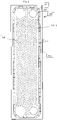
Fig. 1 is a plan view of an upper stencil of a stencil device according to one embodiment of the present invention; -
Fig. 2a is a cross-section view of a stencil device comprising the upper stencil ofFig. 1 and a lower stencil printing stencil according to one embodiment, -
Fig. 2b is an enlarged section view of the area indicated by a circle ofFig. 2a ; and -
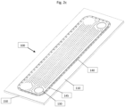
Fig. 2c is a perspective view of the stencil device ofFigs. 2a-2b . - As well known by persons skilled in the art, stencil printing is a technology wherein a stencil is provided between an article to be printed and an applicator of the printing material. Openings are provided in the stencil, such that the printing material will be applied to the article to be printed where the holes are provided.
- As mentioned in the "prior art" section, the invention is intended to provide a method and a device for applying brazing material to a heat exchanger plate to be comprised in a brazed heat exchanger. Brazed heat exchangers are well known by persons skilled in the art and comprise a multitude of heat exchanger plates provided with a pressed pattern of ridges and grooves adapted to contact ridges and grooves of neighboring plates such that the heat exchanger plates are kept on a distance from one another under formation of interplate flow channels for media to exchange heat. The interplate flow channels are in selective fluid communication with port openings provided in each heat exchanger plate, wherein the selectivity is provided by arranging areas surrounding the port openings on different heights, such that there will be a communication between the port opening and the interplate flow channel if the areas surrounding the port openings of neighbouring heat exchanger plates do not contact one another and such that no communication between port opening and the interplate flow channel will occur when the areas surrounding the port openings of neighbouring heat exchanger plates do contact one another. Finally, a circumferentially extending skirt is provided on each heat exchanger plate, wherein the skirts of neighboring heat exchanger plates are arranged to overlappingly contact one another such that the interplate flow channels are sealed from leakage around the circumference of the heat exchanger plate.
- When the brazing of the heat exchanger takes place, the areas surrounding the port openings of neighboring heat exchanger plates contacting one another, the contact points between ridges and grooves of neighboring heat exchanger plates and the overlappingly contacting circumferential skirts are brazed together to seal the heat exchanger and keep the plates together when the heat exchanger is exerted to an internal pressure. It is hence necessary to provide brazing material to all of these areas.
- With reference to
Fig. 1 , astencil 100 for stencil printing brazing material onto a heat exchanger plate is shown. Thestencil 100 is based on aflat base material 110, which e.g. may be manufactured from sheet metal, rubber, plastic, fabric or the like. Thestencil 100 is provided withopenings 120 for applying brazing material to contact points between ridges and grooves of neighboring heat exchanger plates. It should be noted, however, that the ridges and grooves just as well may be shaped in other shapes than ridges and grooves, e.g. as elevated dots adapted to form contact points between neighboring plates. It should be noted that theopenings 120 are placed in pairs, wherein each opening of each pair is placed such that it will be located close to, but not at, a contact point between a ridge and a groove of neighboring heat exchanger plates. In other embodiments of the invention, the openings are not placed in such pairs, but are located at the contact point between ridges and grooves of neighboring heat exchanger plates. - Also, there are two ring-
shaped openings 130 for applying brazing material to areas surrounding port openings of the heat exchanger plate to be printed. Please note that inner portions of the ring-shaped openings are not open - rather, there is a stencil portion held in place within each of the ring-shaped openings 130 by means ofbridges 135. This central stencil portion will hinder excessive amounts of brazing material to be applied to the areas surrounding the port openings. In some cases, thebridges 135 may lead to a leaking braze connection of the areas surrounding the port openings, but such leakage may be reduced by providing dual ring-shaped openings 130 around each port opening, wherein thebridges 135 are angularly offset with respect to one another. - Additionally, the
stencil 100 is provided withcircumferential openings 140. Thecircumferential openings 140 are placed outside a circumference of a heat exchanger plate to be provided with brazing material, and their function will be described with reference toFigs. 2a and 2b . In order to keep the stencil portion comprising theopenings 120 and ring-shapedopenings 130 in place,spokes 145 extend from an area outside thecircumferential openings 140 and the stencil portion comprising theopenings 120 and the ring-shapedopenings 130. - In
Figs 2a and 2b , section views of a stencil device including a lowerstencil printing stencil 150 is shown. The stencil device comprises thestencil 100 and the lowerstencil printing stencil 150, wherein thestencil 100 is an upper stencil. The lowerstencil printing stencil 150 is made from a dense material, e.g. plastic or metal, and has a thickness T exceeding a height of acircumferential skirt 210 of aheat exchanger plate 200. The lower stencil printing stencil comprises alarge opening 190, aninner surface 195 of which being arranged to closely contact an outer surface of thecircumferential skirt 210 of theheat exchanger plate 200. - The
inner surface 195 is provided with a number of brazing material exits 180, which are in fluid communication withmouths 170 bycanals 160. The brazing material exits, the canals and the mouths are placed such that they mate with thecircumferential openings 140 of thestencil 100. - During a stencil printing operation, a
heat exchanger plate 200 to be brazed is placed in thelarge opening 190, and the device is pressed together such that theinner surface 195 closely will fit to the outer surface of thecircumferential skirt 210 of the heat exchanger plate and such that thestencil 100 will be in close contact with ridges R and areas surrounding the port openings of theheat exchanger plate 200 to be stencil printed with brazing material. - Then, in order to stencil print the heat exchanger plate, a brazing material paste is applied to the side of the stencil that is not engaging the
heat exchanger plate 200, preferably by pushing a "sausage" like string of brazing material over thestencil 100. When pushing the string of brazing material over thestencil 100, brazing material will be pushed through theopenings 120 and hence provide brazing material at or close to the contact points between ridges and grooves of neighboring heat exchanger plates, through the ring-shapedopenings 130 to provide brazing material to the area surrounding the port openings and through thecircumferential openings 140. - The brazing material that is pushed through the
circumferential openings 140 will enter themouths 170, which are fluidly connected to the brazing material exits 180 via thecanals 160 and hence, the outer surface of thecircumferential skirt 210 will be provided with brazing material. - When the stencil printing process is done, the
stencil 100 and the lower stencil printing stencil is carefully removed from the heat exchanger plate and the heat exchanger plates are placed in a stack with other heat exchanger plates in order to form a heat exchanger plate pack to be brazed to a heat exchanger. - It should be noted that in order to get a tight seal between the
inner surface 195 of thelarge opening 190 and the outer surface of thecircumferential skirt 210 in order to avoid leakage of brazing material outside the brazing material exits, theinner surface 195 may be coated with a resilient material, e.g. rubber or the like. It may also be advantageous if the resilient material is inflatable by liquid or gas, such that theheat exchanger plate 200 may be placed in and taken away from thelarge opening 190 without contacting itsinner surface 195, while contact may be established by inflating the resilient material during the brazing operation and deflating it after the brazing operation. - During the stencil printing operation, the
heat exchanger plate 200 is held in place by an elevated portion (not shown) of a tray (not shown) adapted to host the heat exchanger plates to be printed. The tray may comprise one or more such elevated portions, depending on the number of heat exchanger plates that are supposed to be printed simultaneously. The elevated portions have an outer perimeter corresponding to an inner perimeter of thecircumferential skirt 210 of theheat exchanger plate 200, such that the heat exchanger plate is held in place during the stencil printing operation. An upper surface of the elevated portion is designed to provide support for the areas surrounding the port openings of the heat exchanger plate and the ridges and/or grooves that are to be stencil printed. - In one embodiment of the invention, the heat exchanger plate(s) is (are) placed on the tray such that the elevated portion keeps the heat exchanger plate in place. This is sufficient for the stencil printing operation. However, depending on the rheological properties of the brazing material, it might be necessary to lock the heat exchanger plate onto the elevated portion once the stencil printing operation is finished and the upper and lower stencils are removed from contact with the heat exchanger plate. This may be achieved in several ways, of which two deserve to be mentioned:
- 1. Applying a vacuum source to the elevated portion, such that a vacuum will hold the plate in place during removal of the upper end lower stencils.
- 2. Retractable locking pins (not shown) extending laterally from the outer perimeter of the elevated portion, said locking pins engaging the inner perimeter of the
circumferential skirt 210 for locking the heat exchanger plate to the elevated portion and being retracted in order to release the heat exchanger plate from the elevated portion. In order to avoid deformation of the circumferential skirts, the locking pins are preferably located at corners of the outer perimeter of the elevated portion. - The stencil device and stencil printing method according to the present invention is intended to provide brazing material to areas at or neighboring contact points between heat exchanger plates to be joined by brazing. The brazing material is preferably provided in the form of a paste having a rheological property resembling the properties of peanut butter.
- The brazing material paste comprises grains of brazing material, i.e. grains of a metal or an alloy having a melting point lower than the material from which the heat exchanger plates are manufactured, a solvent that may vaporize after the brazing material has been applied to the heat exchanger plate and a binder that keeps the brazing material grains at place after the solvent has evaporated. The binder must have sufficient heat resistance to keep the brazing material together until the brazing material has melted.
- Also, the brazing material paste must have excellent adhesive properties in order to adhere properly to the skirts.
- One example of a brazing paste that has been proven to work well is the Höganäs BrazeLet® paste, comprising powder brazing material alloy with a grain size of less than 106 Microns, dispersed in a paste having a metal content of 92 ± 1 wt-%, the remainder binder and solvent. The Brookfield viscosity of the paste at 21 °C, TD-spindle 2.5 rpm = 450 ± 50 Pas.
Claims (15)
- A stencil device (100, 150) for simultaneous stencil printing of brazing material onto elevations (R), areas surrounding port openings, and a circumferential skirt (210) of a heat exchanger plate (200) characterized in that the stencil device comprises an upper stencil (100) having openings (120, 130) for applying brazing material to elevations (R) and areas surrounding port openings of the heat exchanger plate and a lower stencil printing stencil (150) having a large opening (190) for receiving a heat exchanger plate (200) and contacting an outer perimeter of the circumferential skirt of the heat exchanger plate, wherein an inner surface (195) of the large opening (190) comprises brazing material exits (180) for applying brazing material to the circumferential skirts.
- The stencil device of claim 1, wherein the elevations (R) are ridges adapted to form contact points with crossing grooves (G) of neighboring heat exchanger plates (200).
- The stencil device of claim 1 or 2, wherein canals (160) are arranged between circumferential openings (140) of the upper stencil (100) and the brazing material exits (180) for conveying the brazing material to the brazing material exits (180).
- The stencil device of any of the preceding claims, wherein the upper stencil (100) is manufactured from sheet metal, rubber, plastic or fabric.
- The stencil device of any of the preceding claims, wherein the openings (120) of the upper stencil (100) are placed in pairs, wherein each opening of each pair is placed such that it will be located close to, but not at, a contact point between a ridge and a groove of neighboring heat exchanger plates.
- The stencil device of any of the preceding claims, wherein the lower stencil printing stencil (150) is made from a dense material, e.g. plastic or metal, and has a thickness T exceeding a height of a circumferential skirt (210) of a heat exchanger plate (200).
- The stencil device of any of the preceding claims, wherein the inner surface (195) of the lower stencil printing stencil (150) is covered with a resilient material in order to avoid leakage of brazing materiel between the inner surface and an outer surface of a circumferential skirt (210) of the heat exchanger plate to be applied with brazing material.
- The stencil device of claim 7, wherein the resilient material is inflatable to secure a tight fit to the outer surface of the circumferential skirt.
- The stencil device of any of the preceding claims, further comprising at least one elevated portion of a tray adapted to host the heat exchanger plates to be printed, the at least one elevated portion having an outer perimeter corresponding to an inner perimeter of the circumferential skirt 210 of the heat exchanger plate 200.
- The stencil device of claim 9, wherein the elevated portion is provided with means for keeping the heat exchanger plate in place.
- The stencil device of claim 10, wherein the means is a vacuum that will hold the plate in place
- The stencil device of claim 10, wherein the means is retractable locking pins extending laterally from the outer perimeter of the elevated portion, said locking pins engaging the inner perimeter of the circumferential skirt 210 for locking the heat exchanger plate to the elevated portion and being retracted in order to release the heat exchanger plate from the elevated portion.
- Use of a stencil device according to any of the preceding claims for applying heat exchanger plates to be brazed with a brazing material coating.
- A method for simultaneous stencil printing of brazing material onto elevations (R), areas surrounding port openings, and a circumferential skirt (210) of a heat exchanger plate (200), being characterised by comprising the steps of:placing the heat exchanger plate (200) in an opening (190) of a lower stencil printing stencil (150), and bringing an inner surface (195) of the lower stencil printing stencil (150) to contact an outer perimeter of the circumferential skirt (210) of the heat exchanger plate,placing an upper stencil (100) on the heat exchanger plate,applying brazing material to elevations (R) and areas surrounding port openings of the heat exchanger plate through openings (120, 130) in the upper stencil (100), and applying brazing material to the circumferential skirt (210) through brazing material exits (180) in the inner surface (195) of the lower stencil printing stencil (150).
- A method according to claim 14, comprising the step of conveying the brazing material to the brazing material exits (180) by canals (160) arranged between circumferential openings (140) of the upper stencil (100) and the brazing material exits (180).
Applications Claiming Priority (2)
| Application Number | Priority Date | Filing Date | Title |
|---|---|---|---|
| SE1950419A SE543338C2 (en) | 2019-04-04 | 2019-04-04 | Stencil device and method for stencil printing of brazing material onto a heat exchanger plate and use thereof |
| PCT/SE2020/050339 WO2020204798A1 (en) | 2019-04-04 | 2020-04-01 | Stencil device and method for stencil printing of brazing material onto a heat exchanger plate and use thereof |
Publications (2)
| Publication Number | Publication Date |
|---|---|
| EP3946794A1 EP3946794A1 (en) | 2022-02-09 |
| EP3946794B1 true EP3946794B1 (en) | 2023-03-29 |
Family
ID=70285797
Family Applications (1)
| Application Number | Title | Priority Date | Filing Date |
|---|---|---|---|
| EP20718849.1A Active EP3946794B1 (en) | 2019-04-04 | 2020-04-01 | Stencil device and method for stencil printing of brazing material onto a heat exchanger plate and use thereof |
Country Status (6)
| Country | Link |
|---|---|
| US (1) | US12145217B2 (en) |
| EP (1) | EP3946794B1 (en) |
| JP (1) | JP7442544B2 (en) |
| CN (1) | CN113811416B (en) |
| SE (1) | SE543338C2 (en) |
| WO (1) | WO2020204798A1 (en) |
Family Cites Families (21)
| Publication number | Priority date | Publication date | Assignee | Title |
|---|---|---|---|---|
| JPH0337789A (en) | 1989-07-04 | 1991-02-19 | Kazuo Miki | Mode controller utilizing card in gasoline station or the like |
| GB8919436D0 (en) * | 1989-08-25 | 1989-10-11 | Rolls Royce Plc | Heat exchanger and methods of manufacture thereof |
| JPH072775U (en) * | 1993-05-31 | 1995-01-17 | 株式会社土屋製作所 | Heat exchanger core |
| JPH09178384A (en) | 1995-12-22 | 1997-07-11 | Toyo Radiator Co Ltd | Brazing method for plate heat exchanger |
| US6142357A (en) | 1998-10-15 | 2000-11-07 | Mcms, Inc. | Molded selective solder pallet |
| JP2000161877A (en) | 1998-11-24 | 2000-06-16 | Atago Seisakusho:Kk | Plate heat exchanger |
| JP2000337789A (en) | 1999-05-24 | 2000-12-08 | Nhk Spring Co Ltd | Brazing method of plate heat exchanger |
| SE519062C2 (en) | 2001-05-03 | 2003-01-07 | Alfa Laval Corp Ab | Ways of soldering thin heat exchanger plates and soldered plate heat exchangers prepared according to the method |
| CN101687718A (en) * | 2007-04-24 | 2010-03-31 | 陶瓷技术股份公司 | Structural component with ceramic body having a metallized surface |
| AU2008354066B2 (en) * | 2008-04-04 | 2013-02-21 | Alfa Laval Corporate Ab | A plate heat exchanger |
| ES2706986T3 (en) | 2012-03-28 | 2019-04-02 | Alfa Laval Corp Ab | New brazing concept |
| KR102317701B1 (en) | 2012-10-16 | 2021-10-25 | 더 아벨 파운데이션, 인크. | Heat exchanger including manifold |
| JP6154122B2 (en) | 2012-12-12 | 2017-06-28 | 株式会社マーレ フィルターシステムズ | Multi-plate stacked heat exchanger |
| JP6040068B2 (en) | 2013-03-22 | 2016-12-07 | 株式会社ティラド | Manufacturing method of stacked heat exchanger |
| KR102277174B1 (en) | 2013-10-29 | 2021-07-14 | 스웹 인터네셔널 에이비이 | A method of brazing a plate heat exchanger using screen printed brazing material; a plate heat exchanger manufactured by such method |
| WO2016057856A1 (en) * | 2014-10-10 | 2016-04-14 | Modine Manufacturing Company | Brazed heat exchanger and production method |
| CN105140194B (en) | 2015-07-03 | 2018-02-02 | 浙江嘉熙科技有限公司 | Hot superconducting radiator and its manufacture method |
| US10686109B2 (en) * | 2016-12-30 | 2020-06-16 | Lumileds Llc | LED package using electroform stencil printing |
| CN106895725B (en) | 2017-03-09 | 2020-02-07 | 中国科学院上海高等研究院 | Printed circuit board formula fused salt heat exchanger that double-deck board was arranged |
| US11033990B2 (en) * | 2018-11-29 | 2021-06-15 | Raytheon Company | Low cost approach for depositing solder and adhesives in a pattern for forming electronic assemblies |
| SE545690C2 (en) * | 2020-01-30 | 2023-12-05 | Swep Int Ab | A brazed plate heat exchanger and use thereof |
-
2019
- 2019-04-04 SE SE1950419A patent/SE543338C2/en unknown
-
2020
- 2020-04-01 US US17/442,228 patent/US12145217B2/en active Active
- 2020-04-01 JP JP2021557279A patent/JP7442544B2/en active Active
- 2020-04-01 WO PCT/SE2020/050339 patent/WO2020204798A1/en not_active Ceased
- 2020-04-01 EP EP20718849.1A patent/EP3946794B1/en active Active
- 2020-04-01 CN CN202080026888.XA patent/CN113811416B/en active Active
Also Published As
| Publication number | Publication date |
|---|---|
| JP2022528068A (en) | 2022-06-08 |
| US20220184725A1 (en) | 2022-06-16 |
| WO2020204798A1 (en) | 2020-10-08 |
| EP3946794A1 (en) | 2022-02-09 |
| CN113811416B (en) | 2023-07-25 |
| SE1950419A1 (en) | 2020-10-05 |
| JP7442544B2 (en) | 2024-03-04 |
| US12145217B2 (en) | 2024-11-19 |
| SE543338C2 (en) | 2020-12-08 |
| CN113811416A (en) | 2021-12-17 |
Similar Documents
| Publication | Publication Date | Title |
|---|---|---|
| EP3062949B2 (en) | A method of brazing a plate heat exchanger using scren printed brazing material | |
| US11990802B2 (en) | Manufacturing apparatus and manufacturing method for laminated iron core | |
| EP2370772B1 (en) | Brazed heat exchanger | |
| EP3721162B1 (en) | Heat exchanger | |
| US20030007042A1 (en) | Method for bonding inkjet printer cartridge elements | |
| US12145217B2 (en) | Stencil device and method for stencil printing of brazing material onto a heat exchanger plate and use thereof | |
| US4386576A (en) | Glue applicator for paper cup machines | |
| EP1204137A2 (en) | Semiconductor Chip Contacting Method and Apparatus | |
| EP2580062A1 (en) | Medium support member | |
| US11413714B2 (en) | Method for producing a brazed plate heat exchanger | |
| JP2005339518A (en) | Non-contact type data carrier conductive member and method and apparatus for manufacturing the same | |
| JPH0371261B2 (en) | ||
| CN114589963B (en) | Packing box gilding process | |
| JPH088200B2 (en) | Method for manufacturing ceramic electronic component | |
| TW201930160A (en) | Microwavable packaging comprising electrically conductive exothermic layer | |
| JP3099260U (en) | Screen mask | |
| CN112913339A (en) | Method for coating solder paste and mask | |
| EP2969569B1 (en) | Disposable cup insert for pad printing and decorating | |
| JP3739842B2 (en) | Sealed container manufacturing equipment | |
| JPH03283490A (en) | Paste filling device | |
| JPH03241890A (en) | Paste filling method | |
| JPH0364384B2 (en) | ||
| JPH1089483A (en) | Method and apparatus for manufacturing metal gasket | |
| JPH01310767A (en) | Gravure coater | |
| JPH01127018A (en) | End surface adhesion method of filtration material of filter element |
Legal Events
| Date | Code | Title | Description |
|---|---|---|---|
| STAA | Information on the status of an ep patent application or granted ep patent |
Free format text: STATUS: UNKNOWN |
|
| STAA | Information on the status of an ep patent application or granted ep patent |
Free format text: STATUS: THE INTERNATIONAL PUBLICATION HAS BEEN MADE |
|
| PUAI | Public reference made under article 153(3) epc to a published international application that has entered the european phase |
Free format text: ORIGINAL CODE: 0009012 |
|
| STAA | Information on the status of an ep patent application or granted ep patent |
Free format text: STATUS: REQUEST FOR EXAMINATION WAS MADE |
|
| 17P | Request for examination filed |
Effective date: 20211020 |
|
| AK | Designated contracting states |
Kind code of ref document: A1 Designated state(s): AL AT BE BG CH CY CZ DE DK EE ES FI FR GB GR HR HU IE IS IT LI LT LU LV MC MK MT NL NO PL PT RO RS SE SI SK SM TR |
|
| DAV | Request for validation of the european patent (deleted) | ||
| DAX | Request for extension of the european patent (deleted) | ||
| GRAP | Despatch of communication of intention to grant a patent |
Free format text: ORIGINAL CODE: EPIDOSNIGR1 |
|
| STAA | Information on the status of an ep patent application or granted ep patent |
Free format text: STATUS: GRANT OF PATENT IS INTENDED |
|
| INTG | Intention to grant announced |
Effective date: 20221028 |
|
| GRAS | Grant fee paid |
Free format text: ORIGINAL CODE: EPIDOSNIGR3 |
|
| GRAA | (expected) grant |
Free format text: ORIGINAL CODE: 0009210 |
|
| STAA | Information on the status of an ep patent application or granted ep patent |
Free format text: STATUS: THE PATENT HAS BEEN GRANTED |
|
| AK | Designated contracting states |
Kind code of ref document: B1 Designated state(s): AL AT BE BG CH CY CZ DE DK EE ES FI FR GB GR HR HU IE IS IT LI LT LU LV MC MK MT NL NO PL PT RO RS SE SI SK SM TR |
|
| REG | Reference to a national code |
Ref country code: CH Ref legal event code: EP |
|
| REG | Reference to a national code |
Ref country code: DE Ref legal event code: R096 Ref document number: 602020009256 Country of ref document: DE |
|
| REG | Reference to a national code |
Ref country code: AT Ref legal event code: REF Ref document number: 1556329 Country of ref document: AT Kind code of ref document: T Effective date: 20230415 |
|
| REG | Reference to a national code |
Ref country code: IE Ref legal event code: FG4D |
|
| P01 | Opt-out of the competence of the unified patent court (upc) registered |
Effective date: 20230514 |
|
| REG | Reference to a national code |
Ref country code: LT Ref legal event code: MG9D |
|
| PG25 | Lapsed in a contracting state [announced via postgrant information from national office to epo] |
Ref country code: RS Free format text: LAPSE BECAUSE OF FAILURE TO SUBMIT A TRANSLATION OF THE DESCRIPTION OR TO PAY THE FEE WITHIN THE PRESCRIBED TIME-LIMIT Effective date: 20230329 Ref country code: NO Free format text: LAPSE BECAUSE OF FAILURE TO SUBMIT A TRANSLATION OF THE DESCRIPTION OR TO PAY THE FEE WITHIN THE PRESCRIBED TIME-LIMIT Effective date: 20230629 Ref country code: LV Free format text: LAPSE BECAUSE OF FAILURE TO SUBMIT A TRANSLATION OF THE DESCRIPTION OR TO PAY THE FEE WITHIN THE PRESCRIBED TIME-LIMIT Effective date: 20230329 Ref country code: LT Free format text: LAPSE BECAUSE OF FAILURE TO SUBMIT A TRANSLATION OF THE DESCRIPTION OR TO PAY THE FEE WITHIN THE PRESCRIBED TIME-LIMIT Effective date: 20230329 Ref country code: HR Free format text: LAPSE BECAUSE OF FAILURE TO SUBMIT A TRANSLATION OF THE DESCRIPTION OR TO PAY THE FEE WITHIN THE PRESCRIBED TIME-LIMIT Effective date: 20230329 |
|
| REG | Reference to a national code |
Ref country code: NL Ref legal event code: MP Effective date: 20230329 |
|
| REG | Reference to a national code |
Ref country code: AT Ref legal event code: MK05 Ref document number: 1556329 Country of ref document: AT Kind code of ref document: T Effective date: 20230329 |
|
| PG25 | Lapsed in a contracting state [announced via postgrant information from national office to epo] |
Ref country code: SE Free format text: LAPSE BECAUSE OF FAILURE TO SUBMIT A TRANSLATION OF THE DESCRIPTION OR TO PAY THE FEE WITHIN THE PRESCRIBED TIME-LIMIT Effective date: 20230329 Ref country code: NL Free format text: LAPSE BECAUSE OF FAILURE TO SUBMIT A TRANSLATION OF THE DESCRIPTION OR TO PAY THE FEE WITHIN THE PRESCRIBED TIME-LIMIT Effective date: 20230329 Ref country code: GR Free format text: LAPSE BECAUSE OF FAILURE TO SUBMIT A TRANSLATION OF THE DESCRIPTION OR TO PAY THE FEE WITHIN THE PRESCRIBED TIME-LIMIT Effective date: 20230630 Ref country code: FI Free format text: LAPSE BECAUSE OF FAILURE TO SUBMIT A TRANSLATION OF THE DESCRIPTION OR TO PAY THE FEE WITHIN THE PRESCRIBED TIME-LIMIT Effective date: 20230329 |
|
| PG25 | Lapsed in a contracting state [announced via postgrant information from national office to epo] |
Ref country code: SM Free format text: LAPSE BECAUSE OF FAILURE TO SUBMIT A TRANSLATION OF THE DESCRIPTION OR TO PAY THE FEE WITHIN THE PRESCRIBED TIME-LIMIT Effective date: 20230329 Ref country code: RO Free format text: LAPSE BECAUSE OF FAILURE TO SUBMIT A TRANSLATION OF THE DESCRIPTION OR TO PAY THE FEE WITHIN THE PRESCRIBED TIME-LIMIT Effective date: 20230329 Ref country code: PT Free format text: LAPSE BECAUSE OF FAILURE TO SUBMIT A TRANSLATION OF THE DESCRIPTION OR TO PAY THE FEE WITHIN THE PRESCRIBED TIME-LIMIT Effective date: 20230731 Ref country code: ES Free format text: LAPSE BECAUSE OF FAILURE TO SUBMIT A TRANSLATION OF THE DESCRIPTION OR TO PAY THE FEE WITHIN THE PRESCRIBED TIME-LIMIT Effective date: 20230329 Ref country code: EE Free format text: LAPSE BECAUSE OF FAILURE TO SUBMIT A TRANSLATION OF THE DESCRIPTION OR TO PAY THE FEE WITHIN THE PRESCRIBED TIME-LIMIT Effective date: 20230329 Ref country code: AT Free format text: LAPSE BECAUSE OF FAILURE TO SUBMIT A TRANSLATION OF THE DESCRIPTION OR TO PAY THE FEE WITHIN THE PRESCRIBED TIME-LIMIT Effective date: 20230329 |
|
| PG25 | Lapsed in a contracting state [announced via postgrant information from national office to epo] |
Ref country code: SK Free format text: LAPSE BECAUSE OF FAILURE TO SUBMIT A TRANSLATION OF THE DESCRIPTION OR TO PAY THE FEE WITHIN THE PRESCRIBED TIME-LIMIT Effective date: 20230329 Ref country code: PL Free format text: LAPSE BECAUSE OF FAILURE TO SUBMIT A TRANSLATION OF THE DESCRIPTION OR TO PAY THE FEE WITHIN THE PRESCRIBED TIME-LIMIT Effective date: 20230329 Ref country code: IS Free format text: LAPSE BECAUSE OF FAILURE TO SUBMIT A TRANSLATION OF THE DESCRIPTION OR TO PAY THE FEE WITHIN THE PRESCRIBED TIME-LIMIT Effective date: 20230729 |
|
| REG | Reference to a national code |
Ref country code: CH Ref legal event code: PL |
|
| PG25 | Lapsed in a contracting state [announced via postgrant information from national office to epo] |
Ref country code: LU Free format text: LAPSE BECAUSE OF NON-PAYMENT OF DUE FEES Effective date: 20230401 |
|
| REG | Reference to a national code |
Ref country code: DE Ref legal event code: R097 Ref document number: 602020009256 Country of ref document: DE |
|
| REG | Reference to a national code |
Ref country code: BE Ref legal event code: MM Effective date: 20230430 |
|
| PG25 | Lapsed in a contracting state [announced via postgrant information from national office to epo] |
Ref country code: MC Free format text: LAPSE BECAUSE OF FAILURE TO SUBMIT A TRANSLATION OF THE DESCRIPTION OR TO PAY THE FEE WITHIN THE PRESCRIBED TIME-LIMIT Effective date: 20230329 |
|
| PG25 | Lapsed in a contracting state [announced via postgrant information from national office to epo] |
Ref country code: MC Free format text: LAPSE BECAUSE OF FAILURE TO SUBMIT A TRANSLATION OF THE DESCRIPTION OR TO PAY THE FEE WITHIN THE PRESCRIBED TIME-LIMIT Effective date: 20230329 Ref country code: LI Free format text: LAPSE BECAUSE OF NON-PAYMENT OF DUE FEES Effective date: 20230430 Ref country code: DK Free format text: LAPSE BECAUSE OF FAILURE TO SUBMIT A TRANSLATION OF THE DESCRIPTION OR TO PAY THE FEE WITHIN THE PRESCRIBED TIME-LIMIT Effective date: 20230329 Ref country code: CZ Free format text: LAPSE BECAUSE OF FAILURE TO SUBMIT A TRANSLATION OF THE DESCRIPTION OR TO PAY THE FEE WITHIN THE PRESCRIBED TIME-LIMIT Effective date: 20230329 Ref country code: CH Free format text: LAPSE BECAUSE OF NON-PAYMENT OF DUE FEES Effective date: 20230430 |
|
| PLBE | No opposition filed within time limit |
Free format text: ORIGINAL CODE: 0009261 |
|
| STAA | Information on the status of an ep patent application or granted ep patent |
Free format text: STATUS: NO OPPOSITION FILED WITHIN TIME LIMIT |
|
| REG | Reference to a national code |
Ref country code: IE Ref legal event code: MM4A |
|
| PG25 | Lapsed in a contracting state [announced via postgrant information from national office to epo] |
Ref country code: BE Free format text: LAPSE BECAUSE OF NON-PAYMENT OF DUE FEES Effective date: 20230430 |
|
| 26N | No opposition filed |
Effective date: 20240103 |
|
| PG25 | Lapsed in a contracting state [announced via postgrant information from national office to epo] |
Ref country code: IE Free format text: LAPSE BECAUSE OF NON-PAYMENT OF DUE FEES Effective date: 20230401 |
|
| PG25 | Lapsed in a contracting state [announced via postgrant information from national office to epo] |
Ref country code: IE Free format text: LAPSE BECAUSE OF NON-PAYMENT OF DUE FEES Effective date: 20230401 |
|
| PG25 | Lapsed in a contracting state [announced via postgrant information from national office to epo] |
Ref country code: SI Free format text: LAPSE BECAUSE OF FAILURE TO SUBMIT A TRANSLATION OF THE DESCRIPTION OR TO PAY THE FEE WITHIN THE PRESCRIBED TIME-LIMIT Effective date: 20230329 |
|
| PG25 | Lapsed in a contracting state [announced via postgrant information from national office to epo] |
Ref country code: SI Free format text: LAPSE BECAUSE OF FAILURE TO SUBMIT A TRANSLATION OF THE DESCRIPTION OR TO PAY THE FEE WITHIN THE PRESCRIBED TIME-LIMIT Effective date: 20230329 |
|
| PG25 | Lapsed in a contracting state [announced via postgrant information from national office to epo] |
Ref country code: BG Free format text: LAPSE BECAUSE OF FAILURE TO SUBMIT A TRANSLATION OF THE DESCRIPTION OR TO PAY THE FEE WITHIN THE PRESCRIBED TIME-LIMIT Effective date: 20230329 |
|
| PG25 | Lapsed in a contracting state [announced via postgrant information from national office to epo] |
Ref country code: BG Free format text: LAPSE BECAUSE OF FAILURE TO SUBMIT A TRANSLATION OF THE DESCRIPTION OR TO PAY THE FEE WITHIN THE PRESCRIBED TIME-LIMIT Effective date: 20230329 |
|
| GBPC | Gb: european patent ceased through non-payment of renewal fee |
Effective date: 20240401 |
|
| PG25 | Lapsed in a contracting state [announced via postgrant information from national office to epo] |
Ref country code: GB Free format text: LAPSE BECAUSE OF NON-PAYMENT OF DUE FEES Effective date: 20240401 |
|
| PG25 | Lapsed in a contracting state [announced via postgrant information from national office to epo] |
Ref country code: GB Free format text: LAPSE BECAUSE OF NON-PAYMENT OF DUE FEES Effective date: 20240401 |
|
| PG25 | Lapsed in a contracting state [announced via postgrant information from national office to epo] |
Ref country code: CY Free format text: LAPSE BECAUSE OF FAILURE TO SUBMIT A TRANSLATION OF THE DESCRIPTION OR TO PAY THE FEE WITHIN THE PRESCRIBED TIME-LIMIT; INVALID AB INITIO Effective date: 20200401 |
|
| PG25 | Lapsed in a contracting state [announced via postgrant information from national office to epo] |
Ref country code: HU Free format text: LAPSE BECAUSE OF FAILURE TO SUBMIT A TRANSLATION OF THE DESCRIPTION OR TO PAY THE FEE WITHIN THE PRESCRIBED TIME-LIMIT; INVALID AB INITIO Effective date: 20200401 |
|
| PGFP | Annual fee paid to national office [announced via postgrant information from national office to epo] |
Ref country code: TR Payment date: 20260305 Year of fee payment: 7 |
|
| PGFP | Annual fee paid to national office [announced via postgrant information from national office to epo] |
Ref country code: IT Payment date: 20260408 Year of fee payment: 7 |
|
| PGFP | Annual fee paid to national office [announced via postgrant information from national office to epo] |
Ref country code: DE Payment date: 20260417 Year of fee payment: 7 |
|
| PGFP | Annual fee paid to national office [announced via postgrant information from national office to epo] |
Ref country code: FR Payment date: 20260413 Year of fee payment: 7 |