EP3946757B1 - Magnetic assemblies and processes for producing optical effect layers comprising oriented non-spherical magnetic or magnetizable pigment particles - Google Patents
Magnetic assemblies and processes for producing optical effect layers comprising oriented non-spherical magnetic or magnetizable pigment particles Download PDFInfo
- Publication number
- EP3946757B1 EP3946757B1 EP20704053.6A EP20704053A EP3946757B1 EP 3946757 B1 EP3946757 B1 EP 3946757B1 EP 20704053 A EP20704053 A EP 20704053A EP 3946757 B1 EP3946757 B1 EP 3946757B1
- Authority
- EP
- European Patent Office
- Prior art keywords
- magnetic
- generating device
- field generating
- dipole
- center
- Prior art date
- Legal status (The legal status is an assumption and is not a legal conclusion. Google has not performed a legal analysis and makes no representation as to the accuracy of the status listed.)
- Active
Links
Images


Classifications
-
- B—PERFORMING OPERATIONS; TRANSPORTING
- B05—SPRAYING OR ATOMISING IN GENERAL; APPLYING FLUENT MATERIALS TO SURFACES, IN GENERAL
- B05D—PROCESSES FOR APPLYING FLUENT MATERIALS TO SURFACES, IN GENERAL
- B05D3/00—Pretreatment of surfaces to which liquids or other fluent materials are to be applied; After-treatment of applied coatings, e.g. intermediate treating of an applied coating preparatory to subsequent applications of liquids or other fluent materials
- B05D3/06—Pretreatment of surfaces to which liquids or other fluent materials are to be applied; After-treatment of applied coatings, e.g. intermediate treating of an applied coating preparatory to subsequent applications of liquids or other fluent materials by exposure to radiation
- B05D3/061—Pretreatment of surfaces to which liquids or other fluent materials are to be applied; After-treatment of applied coatings, e.g. intermediate treating of an applied coating preparatory to subsequent applications of liquids or other fluent materials by exposure to radiation using U.V.
- B05D3/065—After-treatment
- B05D3/067—Curing or cross-linking the coating
-
- B—PERFORMING OPERATIONS; TRANSPORTING
- B42—BOOKBINDING; ALBUMS; FILES; SPECIAL PRINTED MATTER
- B42D—BOOKS; BOOK COVERS; LOOSE LEAVES; PRINTED MATTER CHARACTERISED BY IDENTIFICATION OR SECURITY FEATURES; PRINTED MATTER OF SPECIAL FORMAT OR STYLE NOT OTHERWISE PROVIDED FOR; DEVICES FOR USE THEREWITH AND NOT OTHERWISE PROVIDED FOR; MOVABLE-STRIP WRITING OR READING APPARATUS
- B42D25/00—Information-bearing cards or sheet-like structures characterised by identification or security features; Manufacture thereof
- B42D25/30—Identification or security features, e.g. for preventing forgery
- B42D25/36—Identification or security features, e.g. for preventing forgery comprising special materials
- B42D25/369—Magnetised or magnetisable materials
-
- B—PERFORMING OPERATIONS; TRANSPORTING
- B05—SPRAYING OR ATOMISING IN GENERAL; APPLYING FLUENT MATERIALS TO SURFACES, IN GENERAL
- B05D—PROCESSES FOR APPLYING FLUENT MATERIALS TO SURFACES, IN GENERAL
- B05D3/00—Pretreatment of surfaces to which liquids or other fluent materials are to be applied; After-treatment of applied coatings, e.g. intermediate treating of an applied coating preparatory to subsequent applications of liquids or other fluent materials
- B05D3/20—Pretreatment of surfaces to which liquids or other fluent materials are to be applied; After-treatment of applied coatings, e.g. intermediate treating of an applied coating preparatory to subsequent applications of liquids or other fluent materials by magnetic fields
- B05D3/207—Pretreatment of surfaces to which liquids or other fluent materials are to be applied; After-treatment of applied coatings, e.g. intermediate treating of an applied coating preparatory to subsequent applications of liquids or other fluent materials by magnetic fields post-treatment by magnetic fields
-
- B—PERFORMING OPERATIONS; TRANSPORTING
- B05—SPRAYING OR ATOMISING IN GENERAL; APPLYING FLUENT MATERIALS TO SURFACES, IN GENERAL
- B05D—PROCESSES FOR APPLYING FLUENT MATERIALS TO SURFACES, IN GENERAL
- B05D5/00—Processes for applying liquids or other fluent materials to surfaces to obtain special surface effects, finishes or structures
- B05D5/06—Processes for applying liquids or other fluent materials to surfaces to obtain special surface effects, finishes or structures to obtain multicolour or other optical effects
- B05D5/065—Processes for applying liquids or other fluent materials to surfaces to obtain special surface effects, finishes or structures to obtain multicolour or other optical effects having colour interferences or colour shifts or opalescent looking, flip-flop, two tones
-
- B—PERFORMING OPERATIONS; TRANSPORTING
- B42—BOOKBINDING; ALBUMS; FILES; SPECIAL PRINTED MATTER
- B42D—BOOKS; BOOK COVERS; LOOSE LEAVES; PRINTED MATTER CHARACTERISED BY IDENTIFICATION OR SECURITY FEATURES; PRINTED MATTER OF SPECIAL FORMAT OR STYLE NOT OTHERWISE PROVIDED FOR; DEVICES FOR USE THEREWITH AND NOT OTHERWISE PROVIDED FOR; MOVABLE-STRIP WRITING OR READING APPARATUS
- B42D25/00—Information-bearing cards or sheet-like structures characterised by identification or security features; Manufacture thereof
- B42D25/30—Identification or security features, e.g. for preventing forgery
- B42D25/36—Identification or security features, e.g. for preventing forgery comprising special materials
- B42D25/378—Special inks
- B42D25/387—Special inks absorbing or reflecting ultraviolet light
-
- B—PERFORMING OPERATIONS; TRANSPORTING
- B42—BOOKBINDING; ALBUMS; FILES; SPECIAL PRINTED MATTER
- B42D—BOOKS; BOOK COVERS; LOOSE LEAVES; PRINTED MATTER CHARACTERISED BY IDENTIFICATION OR SECURITY FEATURES; PRINTED MATTER OF SPECIAL FORMAT OR STYLE NOT OTHERWISE PROVIDED FOR; DEVICES FOR USE THEREWITH AND NOT OTHERWISE PROVIDED FOR; MOVABLE-STRIP WRITING OR READING APPARATUS
- B42D25/00—Information-bearing cards or sheet-like structures characterised by identification or security features; Manufacture thereof
- B42D25/40—Manufacture
- B42D25/405—Marking
- B42D25/41—Marking using electromagnetic radiation
-
- G—PHYSICS
- G06—COMPUTING OR CALCULATING; COUNTING
- G06F—ELECTRIC DIGITAL DATA PROCESSING
- G06F21/00—Security arrangements for protecting computers, components thereof, programs or data against unauthorised activity
- G06F21/30—Authentication, i.e. establishing the identity or authorisation of security principals
- G06F21/31—User authentication
- G06F21/34—User authentication involving the use of external additional devices, e.g. dongles or smart cards
-
- G—PHYSICS
- G06—COMPUTING OR CALCULATING; COUNTING
- G06K—GRAPHICAL DATA READING; PRESENTATION OF DATA; RECORD CARRIERS; HANDLING RECORD CARRIERS
- G06K19/00—Record carriers for use with machines and with at least a part designed to carry digital markings
- G06K19/06—Record carriers for use with machines and with at least a part designed to carry digital markings characterised by the kind of the digital marking, e.g. shape, nature, code
- G06K19/08—Record carriers for use with machines and with at least a part designed to carry digital markings characterised by the kind of the digital marking, e.g. shape, nature, code using markings of different kinds or more than one marking of the same kind in the same record carrier, e.g. one marking being sensed by optical and the other by magnetic means
- G06K19/10—Record carriers for use with machines and with at least a part designed to carry digital markings characterised by the kind of the digital marking, e.g. shape, nature, code using markings of different kinds or more than one marking of the same kind in the same record carrier, e.g. one marking being sensed by optical and the other by magnetic means at least one kind of marking being used for authentication, e.g. of credit or identity cards
- G06K19/12—Record carriers for use with machines and with at least a part designed to carry digital markings characterised by the kind of the digital marking, e.g. shape, nature, code using markings of different kinds or more than one marking of the same kind in the same record carrier, e.g. one marking being sensed by optical and the other by magnetic means at least one kind of marking being used for authentication, e.g. of credit or identity cards the marking being sensed by magnetic means
Definitions
- Coatings or layers comprising oriented magnetic or magnetizable pigment particles are disclosed for example in US 2,570,856 ; US 3,676,273 ; US 3,791,864 ; US 5,630,877 and US 5,364,689 .
- Magnetic or magnetizable pigment particles in coatings allow for the production of magnetically induced images, designs and/or patterns through the application of a corresponding magnetic field, causing a local orientation of the magnetic or magnetizable pigment particles in the unhardened coating, followed by hardening the latter to fix the particles in their positions and orientations. This results in specific optical effects, i.e. fixed magnetically induced images, designs or patterns which are highly resistant to counterfeiting.
- Also described herein are methods of manufacturing a security document or a decorative element or object comprising a) providing a security document or a decorative element or object, and b) providing an optical effect layer (OEL) such as those described herein, in particular such as those obtained by the process described herein, so that it is comprised by the security document or decorative element or object.
- OEL optical effect layer
- the term “and/or” means that either both or only one of the elements linked by the term is present.
- a and/or B shall mean “only A, or only B, or both A and B”.
- only A the term also covers the possibility that B is absent, i.e. "only A, but not B”.
- magnetic direction denotes the direction of the magnetic field vector along a magnetic field line pointing, at the exterior of a magnet, from its North pole to its South pole (see Handbook of Physics, Springer 2002, pages 463-464 ).
- the term "at least” defines a determined quantity or more than said quantity, for example “at least one” means one, two or three, etc.
- security document refers to a document which is protected against counterfeit or fraud by at least one security feature.
- security documents include, without limitation, currency, value documents, identity documents, etc.
- security feature denotes an overt or a covert image, pattern, or graphic element that can be used for the authentication of the document or article carrying it.
- the processes for producing an optical effect layer (OEL) on the substrate (x20) described herein comprises a step iii) of at least partially curing the radiation curable coating composition of step ii) to a second state so as to fix the non-spherical magnetic or magnetizable pigment particles in their adopted positions and orientations.
- the step iii) of at least partially curing the radiation curable coating composition may be carried out subsequently to or partially simultaneously with the step of orienting/aligning at least a part of the non-spherical magnetic or magnetizable pigment particles by applying the magnetic field described herein (step ii)).
- ingredients comprised in a radiation curable coating composition to be applied onto a surface such as a substrate and the physical properties of said radiation curable coating composition must fulfil the requirements of the process used to transfer the radiation curable coating composition to the substrate surface. Consequently, the binder material comprised in the radiation curable coating composition described herein is typically chosen among those known in the art and depends on the coating or printing process used to apply the radiation curable coating composition and the chosen radiation curing process.
- the process for producing the optical effect layer (OEL) described herein may further comprise, for embodiments with platelet-shaped magnetic or magnetizable pigment particles, prior to or at least partially simultaneously with step ii) a step (step ii2)) of exposing the coating layer (x10) to a dynamic magnetic field of a device so as to bi-axially orient at least a part of the platelet-shaped magnetic or magnetizable pigment particles, said step being carried out prior to or partially simultaneously with step ii) and before step iii).
- CN 102529326 B discloses examples of devices comprising spinning magnets that might be suitable for bi-axially orienting magnetic or magnetizable particles magnetic or magnetizable pigment particles.
- suitable devices for bi-axially orienting magnetic or magnetizable particles magnetic or magnetizable pigment particles are shaft-free disc-shaped spinning magnets or magnetic assemblies constrained in a housing made of non-magnetic, preferably non-conducting, materials and are driven by one or more magnet-wire coils wound around the housing. Examples of such shaft-free disc-shaped spinning magnets or magnetic assemblies are disclosed in WO 2015/082344 A1 , WO 2016/026896 A1 and in the co-pending European application 17153905.9 .
- non-spherical magnetic or magnetizable pigment particles described herein include without limitation pigment particles comprising a magnetic layer M made from one or more of a magnetic metal such as cobalt (Co), iron (Fe), gadolinium (Gd) or nickel (Ni); and/or a magnetic alloy of iron, chromium, cobalt or nickel, wherein said magnetic or magnetizable pigment particles may be multilayered structures comprising one or more additional layers.
- a magnetic metal such as cobalt (Co), iron (Fe), gadolinium (Gd) or nickel (Ni)
- a magnetic alloy of iron, chromium, cobalt or nickel wherein said magnetic or magnetizable pigment particles may be multilayered structures comprising one or more additional layers.
- the dielectric/reflector/magnetic/reflector/dielectric/multilayer structures described herein may be multilayer pigment particles being considered as safe for human health and the environment, wherein said magnetic layer comprises a magnetic alloy having a substantially nickel-free composition including about 40 wt-% to about 90 wt-% iron, about 10 wt-% to about 50 wt-% chromium and about 0 wt-% to about 30 wt-% aluminum.
- non-spherical magnetic or magnetizable pigment particles is constituted by non-spherical colorshifting magnetic or magnetizable pigment particles.
- These can more preferably be selected from the group consisting of non-spherical magnetic thin-film interference pigment particles, non-spherical magnetic cholesteric liquid crystal pigment particles, non-spherical interference coated pigment particles comprising a magnetic material and mixtures of two or more thereof.
- Preferred six-layer Fabry-Perot multilayer structures consist of absorber/dielectric/reflector/magnetic/dielectric/absorber multilayer structures.
- Preferred seven-layer Fabry Perot multilayer structures consist of absorber/dielectric/reflector/magnetic/reflector/dielectric/absorber multilayer structures such as disclosed in US 4,838,648 .
- the reflector layers described herein are independently made from one or more materials selected from the group consisting of metals and metal alloys, preferably selected from the group consisting of reflective metals and reflective metal alloys, more preferably selected from the group consisting of aluminum (Al), silver (Ag), copper (Cu), gold (Au), platinum (Pt), tin (Sn), titanium (Ti), palladium (Pd), rhodium (Rh), niobium (Nb), chromium (Cr), nickel (Ni), and alloys thereof, even more preferably selected from the group consisting of aluminum (Al), chromium (Cr), nickel (Ni) and alloys thereof, and still more preferably aluminum (Al).
- metals and metal alloys preferably selected from the group consisting of reflective metals and reflective metal alloys, more preferably selected from the group consisting of aluminum (Al), silver (Ag), copper (Cu), gold (Au), platinum (Pt), tin (Sn), titanium (Ti), palla
- the first magnetic-field generating device (x30) described herein comprises the three or more first dipole magnets (x31 a1 , x31 a2 , ...) described herein, wherein each of said first dipole magnets (x31 a1 , x31 a2 , ...) having its center (C x31-a1 , C 3x1-a2 ,...) disposed on the loop (x32) in the first plane (P) and wherein said first dipole magnets (x31 a1 , x31 a2 , ...) have their magnetic axes oriented to be substantially parallel to the first plane (P) (and substantially parallel to the substrate (x20)). As shown for example in Fig.
- all the angles ⁇ i have a value of 90°, or all the all the angles ⁇ i have a value of 270°, or some of the all the angles ⁇ i have a value of 90° and the remaining one(s) has/have a value of 270°).
- loops (x32) include a ring or circle, a rectangle or square, a triangle, a (regular or irregular) pentagon, a (regular or irregular) hexagon, a (regular or irregular) heptagon, a (regular or irregular) octagon, , etc.
- the one or more supporting matrixes (x33) described herein are independently made of one or more non-magnetic materials.
- the non-magnetic materials are preferably selected from the group consisting of non-magnetic metals and engineering plastics and polymers.
- Non-magnetic metals include without limitation aluminum, aluminum alloys, brasses (alloys of copper and zinc), titanium, titanium alloys and austenitic steels (i.e. non-magnetic steels).
- the second magnetic-field generating device (x40) described herein is disposed above the first magnetic-field generating device (x30) described herein; in other words, during the process to produce the optical effect layer (OEL) described herein, the substrate (x20) carrying the coating layer (x10) comprising the non-spherical magnetic or magnetizable pigment particles is disposed above the second magnetic-field generating device (x40) and said second magnetic-field generating device (x40) is disposed above the first magnetic-field generating device (x30).
- the first magnetic-field generating device (x30) and the second magnetic-field generating device (x40) are substantially centered with respect to one another.
- the one or more third dipole magnets (x51) of the third magnetic-field generating device (x50) described herein are disposed in an alternating manner on the loop (x32) and are disposed between one or more of the first dipole magnets (x31 a1 , x31 a2 , ...) of the first magnetic-field generating device (x30).
- the first magnetic-field generating device (x30) and the one or more third dipole magnets (x51) are arranged in such a way that angles ⁇ are respectively formed between the vectors C x 41 C x 31- ax and C x 41 C x 51 , i.e. the angles formed between the straight line from the projection point (C x41 ) to the center (C x31-a1 , C x31-a2 ,...) of the first dipole magnet (x31 a1 , x31 a2 , ...) and the straight line from the projection point (C x41 ) to the center (C x51 ) of the adjacent (but not necessarily in direct contact) third dipole magnet (x51).
- the one or more pole pieces (x60) described herein are made from iron or from a plastic material in which magnetizable particles are dispersed.
- the one or more pole piece (x60) described herein are made of iron.
- the one or more pole pieces (x60) described herein are independently disc-shaped, square-shaped or rectangleshaped pole pieces (x60).
- the one or more pole pieces (x60) described herein is disposed below the first magnetic-field generating device (x30) described herein; in other words, during the process to produce the optical effect layer (OEL) described herein, the substrate (x20) carrying the coating layer (x10) comprising the non-spherical magnetic or magnetizable pigment particles is disposed above the second magnetic-field generating device (x40), said second magnetic-field generating device (x40) is disposed above the first magnetic-field generating device (x30) and said first magnetic-field generating device (x30) is disposed above the one or more pole pieces (x60).
- the first magnetic-field generating device (x30), the second magnetic-field generating device (x40) and the one or more pole pieces (x60) are substantially centered with respect to one another.
- Suitable high-coercivity materials are materials having a maximum value of energy product (BH) max of at least 20 kJ/m 3 , preferably at least 50 kJ/m 3 , more preferably at least 100 kJ/m 3 , even more preferably at least 200 kJ/m 3 .
- BH energy product
- cobalt ferrite CoFe 2 0 4
- magnetite Fe 3 O 4
- M is a bivalent metal ion
- ceramic 8 Si-1-5
- the magnetized plate (x80) described herein in particular the magnetized plate (x80) made of the composite material comprising the polymer and the soft-magnetic material or hard-magnetic material described herein, can also be cut or molded to a particular size and shape, rather than engraved. Holes may be cut out of it, or cut-out pieces may be assembled on a support.
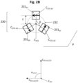
- the magnetic assembly (200) comprises a first magnetic-field generating device (230) comprising three or more, in particular three, first dipole magnets (231 a1 , 231 a2 , 231 a3 ) embedded in a square-shaped supporting matrix (233) and a second magnetic-field generating device (240) comprising a second dipole magnet (241), wherein the second magnetic-field generating device (240) is disposed above the first magnetic-field generating device (230).
- a first magnetic-field generating device (230) comprising three or more, in particular three, first dipole magnets (231 a1 , 231 a2 , 231 a3 ) embedded in a square-shaped supporting matrix (233) and a second magnetic-field generating device (240) comprising a second dipole magnet (241), wherein the second magnetic-field generating device (240) is disposed above the first magnetic-field generating device (230).
- the three first dipole magnets (231 a1 , 231 a2 , 231 a3 ) have their magnetic axes substantially tangential to the ring (232) at the position of their respective center (C 231-a1 , C 231-a2 and C 231-a3 ).
- the center of the first magnetic-field generating device (230), i.e. the center of the square-shaped supporting matrix (233), and the center of the second magnetic-field generating device (240), i.e. the center of the second dipole magnet (241), are substantially centered with respect to one another and are substantially centered with respect to the projection point (C 241 ) of the center of the cylindrical dipole magnet (241).
- the second dipole magnet (241) has its magnetic axis substantially perpendicular to the plane (P) and substantially perpendicular to the substrate (220) with its North pole pointing towards (i.e. facing) the substrate (220).
- the second dipole magnet (241) is disposed in direct contact and above the supporting matrix (233).
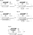
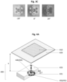
- the resulting OEL produced with the magnetic assembly (200) illustrated in Fig. 2A-B is shown in Fig. 2C at different viewing angles by tilting the substrate (220) between -20° and +20°.
- the so-obtained OEL provides the optical impression of a ring surrounded by three loop-shaped bodies having their shape and their brightness varying upon tilting the optical effect layer (OEL).
- the distance (d) from the uppermost surface of the first magnetic-field generating device (330), i.e. the uppermost surface of the six first dipole magnets (331 a1 , ..., 331 a6 ), and the lowermost surface of the second dipole magnet (341) described herein, i.e. the lowermost surface second dipole magnet (341) is equal to or smaller than the thickness (Z) of the second dipole magnet (341).
- the second distance (d) is preferably between about 0 mm and about 5 mm, more preferably between about 0 mm and about 1 mm and still more preferably about 0 mm.
- the eight first dipole magnets (431 a1 , ..., 431 a8 ) of the first magnetic-field generating device (430) have their magnetic axes substantially parallel to the plane (P), substantially parallel to the substrate (420) and substantially perpendicular to the magnetic axis of the second dipole magnet (441) of the second magnetic-field generating device (440).
- the eight first dipole magnets (431 a1 , ..., 431 a8 ) are distributed around the projection point (C 441 ) of the center of the second dipole magnet (441).
- the distances Y between the projection point (C 441 ) of the center of the second dipole magnet (441) and the center (C 431-a1 , ..., C 431-a8 ) of each of said eight first dipole magnets (431 a1 , ..., 431 a8 ) are equal to each other.
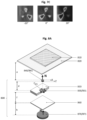
- the resulting OEL produced with the magnetic assembly (400) illustrated in Fig. 4A-B is shown in Fig. 4C at different viewing angles by tilting the substrate (420) between -20° and +20°.
- the so-obtained OEL provides the optical impression of a ring surrounded by four loop-shaped bodies having their shape and their brightness varying upon tilting the optical effect layer (OEL).
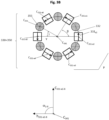
- the nine first dipole magnets (531 a1 , ..., 531 a9 ) are arranged in such a way that each of their centers (C 531-a1 , ..., C 531-a9 ) is disposed on a loop (532), in particular a ring, in the plane (P) being substantially parallel to the substrate (520).
- the projection of the center of the second dipole magnet (541) on the plane (P) is located at the projection point (C 541 ) and is symmetrically disposed within the ring (532), i.e. the projection point (C 541 ) also corresponds to the center of the ring (532).
- the three third dipole magnets (551) of the third magnetic-field generating device (550) are arranged in such a way that each of their centers are disposed on the loop, in particular the ring, (532) in the plane (P) being substantially parallel to the substrate (520).
- the center of the first magnetic-field generating device (530), i.e. the center of the square-shaped supporting matrix (533), and the center of the second magnetic-field generating device (240), i.e. the center of the second dipole magnet (541), are substantially centered with respect to one another and are substantially centered with respect to the projection point (C 541 ) of the center of the cylindrical dipole magnet (541).
- the center of the square-shaped pole piece (560) and the center of the disc-shaped fourth dipole magnet (571) are substantially centered with respect to one another and are substantially centered with respect to the projection point (C 541 ) of the center of the cylindrical dipole magnet (541).
- the three first dipole magnets (631 a1 , 631 a2 , 631 a3 ) are arranged in such a way that each of their centers (C 631-a1 , C 631-a2 and C 631-a3 ) is disposed on a loop (632), in particular a ring, in the plane (P) being substantially parallel to the substrate (620).
- the projection of the center of the second dipole magnet (641) on the plane (P) is located at the projection point (C 641 ) and is symmetrically disposed within the ring (632), i.e. the projection point (C 641 ) also corresponds to the center of the ring (632).
- the three first dipole magnets (631 a1 , 631 a2 , 631 a3 ) are evenly distributed around the projection point (C 641 ) of the center of the second dipole magnet (641).
- the three angles ⁇ respectively formed by the vectors C 641 C 631- a 1 (corresponding to the straight line from the projection point (C 641 ) to the center C 631-a1 of the cubic first dipole magnet (631 a1 )) and C 641 C 631- a 2 ; the vectors C 641 C 631- a 2 and C 641 C 631- a 3 ; and the vectors C 641 C 631- a 3 and C 641 C 631- a 1 are equal to each other, in particular 120°.
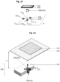
- Fig. 7A-C illustrate an example of a magnetic assembly (700) suitable for producing optical effect layers (OELs) comprising non-spherical magnetic or magnetizable pigment particles on a substrate (720) according to the present invention.
- OELs optical effect layers
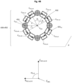
- the magnetic assembly (700) comprises a first magnetic-field generating device (730) comprising three or more, in particular six, first dipole magnets (731 a1 , ..., 731 a6 ) embedded in a square-shaped supporting matrix (733) and a second magnetic-field generating device (740) comprising a second dipole magnet (741), wherein the second magnetic-field generating device (740) is disposed above the first magnetic-field generating device (730).
- the six first dipole magnets (731 a1 , ..., 731 a6 ) of the first magnetic-field generating device (730) have their magnetic axes substantially parallel to the plane (P), substantially parallel to the substrate (720) and substantially perpendicular to the magnetic axis of the second dipole magnet (741) of the second magnetic-field generating device (740).
- the six angles ⁇ respectively formed by the vectors C 741 C 731- a 1 (corresponding to the straight line from the projection point (C 741 ) to the center C 731-a1 of the parallelepiped first dipole magnet (731 a1 )) and C 741 C 731- a 2 ; the vectors C 741 C 731- a 2 and C 741 C 731- a 3 ; the vectors C 741 C 731- a 3 and C 741 C 731- a 4 ; the vectors C 741 C 731- a 4 and C 741 C 731- a 5 ; the vectors C 741 C 731- a 5 and C 741 C 731- a 6 ; and the vectors C 741 C 731- a 6 and C 741 C 731- a 1 are equal to each other, in particular 60°.
- the distance (d) from the uppermost surface of the first magnetic-field generating device (730), i.e. the uppermost surface of the six first dipole magnets (731 a1 , ..., 731 a6 ), and the lowermost surface of the second dipole magnet (741) is equal to or smaller than the thickness (Z) of the second dipole magnet (741).
- the second distance (d) is preferably between about 0 mm and about 5 mm, more preferably between about 0 mm and about 1 mm and still more preferably about 0 mm.
- the disc-shaped fourth dipole magnet (771) of the fourth magnetic-field generating device (770) is disposed below the square-shaped pole piece (760).
- the disc-shaped fourth dipole magnet (771) has its magnetic axis substantially perpendicular to the plane (P), substantially perpendicular to the substrate (720) and substantially perpendicular to the magnetic axis of the three first dipole magnets (731 a1 , ... , 731 a6 ) of the first magnetic assembly (730) with its North pole pointing towards (i.e. facing) the substrate (720).
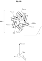
- Fig. 8A-C illustrate an example of a magnetic assembly (800) suitable for producing optical effect layers (OELs) comprising non-spherical magnetic or magnetizable pigment particles on a substrate (820) according to the present invention.
- OELs optical effect layers
- the distance (d) from the uppermost surface of the first magnetic-field generating device (830), i.e. the uppermost surface of the six first dipole magnets (831 a1 , ... , 831 a6 ), and the lowermost surface of the second magnetic-field generating device (840), i.e. the uppermost surface of the second dipole magnet (841), is equal to or smaller than the thickness (Z) of the second dipole magnet (841).
- the second distance (d) is preferably between about 0 mm and about 5 mm, more preferably between about 0 mm and about 1 mm and still more preferably about 0 mm.
- the disc-shaped fourth dipole magnet (871) of the fourth magnetic-field generating device (870) is disposed below the square-shaped pole piece (860).
- the disc-shaped fourth dipole magnet (871) has its magnetic axis substantially perpendicular to the plane (P), substantially perpendicular to the substrate (820) and substantially perpendicular to the magnetic axis of the six first dipole magnets (831 a1 , ... , 831 a6 ) of the first magnetic assembly (530) with its North pole pointing towards (i.e. facing) the substrate (820).
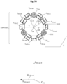
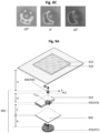
- the six angles ⁇ respectively formed by the vectors C 941 C 931- a 1 (corresponding to the straight line from the projection point (C 941 ) to the center C 931-a1 of the cylindrical first dipole magnet (931 a1 )) and C 941 C 931- a 2 ; the vectors C 941 C 931- a 2 and C 941 C 931- a 3 ; the vectors C 941 C 931- a 3 and C 941 C 931- a 4 ; the vectors C 941 C 931- a 4 and C 941 C 931- a 5 ; the vectors C 941 C 931- a 5 and C 941 C 931- a 6 ; and the vectors C 941 C 931- a 6 and C 941 C 931- a 1 are equal to each other, in particular 60°.
- the distances Y between the projection point (C 941 ) of the center of the second dipole magnet (941) and the center (C 931-a1 , ..., C 931-a6 ) of each of said six first dipole magnets (931 a1 , ... , 931 a6 ) are equal to each other.
- the rotating magnetic cylinder is meant to be used in, or in conjunction with, or being part of a printing or coating equipment, and bearing one or more magnetic assemblies described herein.
- the rotating magnetic cylinder is part of a rotary, sheet-fed or web-fed industrial printing press that operates at high printing speed in a continuous way.
- articles in particular security documents, decorative elements or objects, comprising the optical effect layer (OEL) produced according to the present invention.
- OEL optical effect layer
- the articles, in particular security documents, decorative elements or objects may comprise more than one (for example two, three, etc.) OELs produced according to the present invention.
- the optical effect layer may be produced onto an auxiliary substrate such as for example a security thread, security stripe, a foil, a decal, a window or a label and consequently transferred to a security document in a separate step.
- an auxiliary substrate such as for example a security thread, security stripe, a foil, a decal, a window or a label
- the three first dipole magnets (231 a1 , 231 a2 , 231 a3 ) had their magnetic axes substantially tangential to the ring (232) at the position of their respective center (C 231-a1 , C 231-a2 and C 231-a3 ).
- the eight cylindrical first dipole magnets (431 a1 , ... , 431 a8 ) of the first magnetic-field generating device (430) and the four cylindrical third dipole magnets (451) of the third magnetic-field generating device (450) had the following dimensions: 2 mm (diameter) x 2 mm (thickness) and were made of NdFeB N45.
- the eight cylindrical first dipole magnets (431 a1 , ... , 431 a8 ) were arranged in such a way that each center (C 431-a1 , ..., C 431-a8 ) was disposed on a ring (432) in the plane (P) being substantially parallel to the substrate (420).
- the cylindrical second dipole magnet (441) of the second magnetic-field generating device (440) had the following dimensions: 4 mm (X, diameter) x 3 mm (Z, thickness) and was made of NdFeB N45.
- the projection of the center of the cylindrical second dipole magnet (441) of the second magnetic-field generating device (440) on the plane (P) was located at the projection point (C 441 ) and was symmetrically disposed within the ring (432), i.e. the projection point (C 441 ) also corresponded to the center of the symmetric the ring (432).
- the square-shaped supporting matrix (433) had the following dimensions: 30 mm x 30 mm x 6 mm and was made of polyoxymethylene (POM).
- the square-shaped supporting matrix (433) comprised twelve cubic indentations for holding the eight cylindrical first dipole magnets (431 a1 , ... , 431 a8 ) and the four cylindrical third dipole magnets (451), said indentations having the following dimensions: 2 mm x 2 mm x 2 mm so that the uppermost surface of said twelve cylindrical dipole magnets (431 a1 , ... , 431 a8 and 451) was flush with the uppermost surface of the square-shaped supporting matrix (433).
- the cylindrical second dipole magnet (441) had its magnetic axis substantially perpendicular to the plane (P), perpendicular to the substrate (420), substantially perpendicular to the magnetic axis of the eight cylindrical first dipole magnets (431 a1 , ... , 431 a8 ) of the first magnetic assembly (430), substantially parallel to the magnetic axis of the four cylindrical third dipole magnet (451) of the third magnetic assembly (450) with its North pole pointing towards (i.e. facing) the substrate (420).
- the cylindrical second dipole magnet (441) was disposed in direct contact and above the square-shaped supporting matrix (433).
- the center of the first magnetic-field generating device (430) and the center of the second magnetic-field generating device (440) were substantially centered with respect to one another and were substantially centered with respect to the projection point (C 441 ) of the center of the cylindrical dipole magnet (441).
- the nine cylindrical first dipole magnets (531 a1 , ... , 531 a9 ) their North pole pointing all in the same circular direction (i.e. counterclockwise circular direction).
- the distances Y between the projection point (C 541 ) of the center of the cylindrical second dipole magnet (541) and the center (C 531-a1 , ..., C 531-a9 ) of each of said nine cylindrical dipole magnets (531 a1 , ... , 531 a9 ) were equal to each other, said distances being 5 mm.
- the three cylindrical third dipole magnets (551) of the third magnetic-field generating device (550) were evenly distributed on the ring (532) and around the projection point (C 541 ) of the center of the cylindrical dipole magnet (541).
- the angles ⁇ respectively formed by the vectors C 541 C 531- ax (corresponding to the straight line from the projection point (C 541 ) to the center C 531-ax of a first dipole magnet (531 ax )) and C 541 C 551 (corresponding to the straight line from the projection point (C 541 ) to the center of an adjacent cylindrical third dipole magnet (551)) were equal to each other, said value being 30°.
- the distance (e) from the uppermost surface of the second magnetic-field generating device (540), i.e. the uppermost surface of the cylindrical second dipole magnet (541), and the lowermost surface of the substrate (520) facing the device (500) was 0.6 mm.
- the resulting OEL produced with the magnetic assembly (500) illustrated in Fig. 5A-B is shown in Fig. 5C at different viewing angles by tilting the substrate (520) between -20° and +20°.
- the so-obtained OEL provides the optical impression of a ring surrounded by three loop-shaped bodies having their shape and their brightness varying upon tilting the optical effect layer (OEL).
- the second magnetic-field generating device (640) was disposed above the first magnetic-field generating device (630), the first magnetic-field generating device (630) was disposed above the square-shaped pole piece (660) and the square-shaped pole piece (660) was disposed above the fourth magnetic-field generating device (670).
- the three cubic first dipole magnets (631 a1 , 631 a2 , 631 a3 ) of the first magnetic-field generating device (630) had the following dimensions: 3 mm x 3 mm x 3 mm and were made of NdFeB N45. As shown in Fig. 6B , the three cubic first dipole magnets (631 a1 , 631 a2 , 631 a3 ) were arranged in such a way that each center (C 631-a1 , C 631-a2 and C 631-a3 ) was disposed on a ring (632) in the plane (P) being substantially parallel to the substrate (620).
- the cylindrical second dipole magnet (641) of the second magnetic-field generating device (640) had the following dimensions: 4 mm (X, diameter) x 3 mm (Z, thickness) and was made of NdFeB N45.
- the projection of the center of the cylindrical second dipole magnet (641) on the plane (P) was located at the projection point (C 641 ) and was symmetrically disposed within the ring (632), i.e. the projection point (C 641 ) also corresponded to the center of the symmetric the ring (632).
- the three cubic first dipole magnets (631 a1 , 631 a2 , 631 a3 ) of the first magnetic-field generating device (630) had their magnetic axes substantially parallel to the plane (P), substantially parallel to the substrate (620) and substantially perpendicular to the magnetic axis of the cylindrical second dipole magnet (641) of the second magnetic-field generating device (640).
- the three cubic first dipole magnets (631 a1 , 631 a2 , 631 a3 ) had their North pole pointing all in the same circular direction (i.e. counterclockwise circular direction).
- the three first dipole magnets (631 a1 , 631 a2 , 631 a3 ) had their magnetic axes substantially tangential to the ring (632) at the position of their respective center (C 631-a1 , C 631-a2 and C 631-a3 ).
- the distances Y between the projection point (C 641 ) of the center of the cylindrical second dipole magnet (641) and the center (C 631-a1 , C 631-a2 and C 631-a3 ) of each of said three cubic first dipole magnets (631 a1 , 631 a2 , 631 a3 ) were equal to each other, said distances being 3.5 mm.
- the cylindrical second dipole magnet (641) had its magnetic axis substantially perpendicular to the plane (P) and substantially perpendicular to the substrate (620) with its North pole pointing towards (i.e. facing) the substrate (620).
- the cylindrical second dipole magnet (641) was disposed in direct contact and above the square-shaped supporting matrix (633).
- the disc-shaped fourth dipole magnet (671) of the fourth magnetic-field generating device (670) had the following dimensions: 20 mm (diameter) x 1.5 mm (thickness) and was made of NdFeB N40.
- the disc-shaped fourth dipole magnet (671) of the fourth magnetic-field generating device (670) had its magnetic axis substantially perpendicular to the plane (P), substantially perpendicular to the substrate (620) and substantially perpendicular to the magnetic axis of the three cylindrical first dipole magnets (631 a1 , 631 a2 , 631 a3 ) of the first magnetic assembly (630) with its North pole pointing towards (i.e. facing) the substrate (620).
- the center of the first magnetic-field generating device (630) and the center of the second magnetic-field generating device (640) were substantially centered with respect to one another and were substantially centered with respect to the projection point (C 641 ) of the center of the cylindrical dipole magnet (641).
- the center of the square-shaped pole piece (660) and the center of the disc-shaped fourth dipole magnet (671) were substantially centered with respect to one another and were substantially centered with respect to the projection point (C 641 ) of the center of the cylindrical dipole magnet (641).
- the distance (d) (not shown in Fig 6A for clarity purpose) from the uppermost surface of the first magnetic-field generating device (630), i.e. the uppermost surface of the three cubic first dipole magnets (631 a1 , 631 a2 , 631 a3 ) of the first magnetic-field generating device (630) (also corresponding to the uppermost surface of the square-shaped supporting matrix (633), and the lowermost surface of the second magnetic-field generating device (640), i.e. the lowermost surface of the cylindrical dipole magnet (641), was 0 mm.
- the distance (f) from the lowermost surface of the first magnetic-field generating device (630), i.e. the lowermost surface of the square-shaped supporting matrix (633), and the uppermost surface of the square-shaped pole piece (660) was 0 mm, i.e. the square-shaped supporting matrix (633) and the square-shaped pole piece (660) were in direct contact (the distance from the lowermost surface of the three cubic first dipole magnets (631 a1 , 631 a2 , 631 a3 ) and the uppermost surface of the square-shaped pole piece (660) was about 2.5 mm).
- the six parallelepiped first dipole magnets (731 a1 , ... , 731 a6 ) of the first magnetic-field generating device (730) had the following dimensions: 10 mm x 4 mm x 1 mm and were made of NdFeB N45. As shown in Fig. 7B , the six parallelepiped first dipole magnets (731 a1 , ... , 731 a6 ) were arranged in such a way that each center (C 731-a1 , ..., C 731-a6 ) was disposed on a ring (732) in the plane (P) being substantially parallel to the substrate (720).
- the six parallelepiped first dipole magnets (731 a1 , ... , 731 a6 ) were evenly distributed around the projection point (C 741 ) of the center of the cylindrical dipole magnet (741).
- the six angles ⁇ respectively formed by the vectors C 741 C 731- a 1 (corresponding to the straight line from the projection point (C 741 ) to the center C 731-a1 of the parallelepiped first dipole magnet (731 a1 )) and C 741 C 731- a 2 ; the vectors C 741 C 731- a 2 and C 741 C 731- a 3 ; the vectors C 741 C 731- a 3 and C 741 C 731- a 4 ; the vectors C 741 C 731- a 4 and C 741 C 731- a 5 ; the vectors C 741 C 731- a 5 and C 741 C 731- a 6 ; and the vectors C 741 C 731- a 6 and C 7
- the square-shaped pole piece (760) had the following dimensions: 30 mm x 30 mm x 1 mm and was made of iron.
- the disc-shaped fourth dipole magnet (771) of the fourth magnetic-field generating device (770) had the following dimensions: 20 mm (diameter) x 4 mm (thickness) and was made of NdFeB N45.
- the disc-shaped fourth dipole magnet (771) of the fourth magnetic-field generating device (770) had its magnetic axis substantially perpendicular to the plane (P), substantially perpendicular to the substrate (720) and substantially perpendicular to the magnetic axis of the six parallelepiped first dipole magnets (731 a1 , ... , 731 a6 ) of the first magnetic assembly (730) with its North pole pointing towards (i.e. facing) the substrate (720).
- the magnetic assembly (800) used to prepare the optical effect layer (OEL) of Example 7 on the substrate (820) is illustrated in Fig. 8A-B .
- the magnetic assembly (800) was configured for receiving the substrate (820) in an orientation parallel to a first plane (P).
- the magnetic assembly (800) comprised a first magnetic-field generating device (830) comprising six cylindrical first dipole magnets (831 a1 , ... , 831 a6 ) embedded in a square-shaped supporting matrix (833), a second magnetic-field generating device (840) comprising a cylindrical first dipole magnet (841) a square-shaped pole piece (860) and a fourth magnetic-field generating device (870) comprising a disc-shaped fourth dipole magnet (871).
- the six cylindrical first dipole magnets (831 a1 , ... , 831 a6 ) of the first magnetic-field generating device (830) had the following dimensions: 2 mm (diameter) x 4 mm (length) and were made of NdFeB N45. As shown in Fig. 8B , the six cylindrical first dipole magnets (831 a1 , ... , 831 a6 ) were arranged in such a way that each center (C 831-a1 , ... C 831-a6 ) was disposed on a ring (832) in the plane (P) being substantially parallel to the substrate (820).
- the six angles ⁇ 1-6 respectively formed by i) the vectors ( C 841 C 831- a 1 ,... , C 841 C 831- a 6 ) (i.e. the vectors between the projection point (C 841 ) and the center (C 831-a1 , ..., C 831-a9 ) of each respective dipole magnet of the first magnetic-field generating device (830)) and ii) the vectors ( h 431- a 1 , ..., h 431- a 8 ), when measured in a counterclockwise direction, were equal to each other, in particular 225°.
- the disc-shaped fourth dipole magnet (871) of the fourth magnetic-field generating device (870) had the following dimensions: 20 mm (diameter) x 3 mm (thickness) and was made of NdFeB N40.
- the cylindrical second dipole magnet (941) of the second magnetic-field generating device (940) had the following dimensions: 4 mm (X, diameter) x 2 mm (Z, thickness) and was made of NdFeB N45.
- the projection of the center of the cylindrical second dipole magnet (941) on the plane (P) was located at the projection point (C 941 ) and was symmetrically disposed within the ring (932), i.e. the projection point (C 941 ) also corresponded to the center of the symmetric the ring (932).
- the distances Y between the projection point (C 941 ) of the center of the cylindrical second dipole magnet (941) and the center (C 931-a1 , ..., C 931-a6 ) of each of said six cylindrical first dipole magnets (931 a1 , ... , 931 a6 ) were equal to each other, said distances Y being 4 mm.
- the cylindrical second dipole magnet (941) had its magnetic axis substantially perpendicular to the plane (P), perpendicular to the substrate (920) and substantially perpendicular to the magnetic axis of the six first cylindrical dipole magnets (931 a1 , ... , 931 a6 ) of the first magnetic assembly (930) with its North pole pointing towards (i.e. facing) the substrate (920).
- the cylindrical second dipole magnet (941) was disposed in direct contact and above the supporting matrix (933).
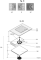
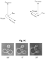
- the resulting OEL produced with the magnetic assembly (900) illustrated in Fig. 9A-B is shown in Fig. 9C at different viewing angles by tilting the substrate (920) between -20° and +20°.
- the so-obtained OEL provides the optical impression of a ring surrounded by three loop-shaped bodies having their shape and brightness varying upon tilting the optical effect layer (OEL).
Landscapes
- Engineering & Computer Science (AREA)
- Physics & Mathematics (AREA)
- Theoretical Computer Science (AREA)
- General Physics & Mathematics (AREA)
- Computer Security & Cryptography (AREA)
- Health & Medical Sciences (AREA)
- Electromagnetism (AREA)
- Plasma & Fusion (AREA)
- General Health & Medical Sciences (AREA)
- Manufacturing & Machinery (AREA)
- Toxicology (AREA)
- Computer Hardware Design (AREA)
- General Engineering & Computer Science (AREA)
- Software Systems (AREA)
- Credit Cards Or The Like (AREA)
- Printing Methods (AREA)
- Laminated Bodies (AREA)
- Application Of Or Painting With Fluid Materials (AREA)
- Magnetic Record Carriers (AREA)
Applications Claiming Priority (2)
| Application Number | Priority Date | Filing Date | Title |
|---|---|---|---|
| EP19165774 | 2019-03-28 | ||
| PCT/EP2020/054042 WO2020193009A1 (en) | 2019-03-28 | 2020-02-17 | Magnetic assemblies and processes for producing optical effect layers comprising oriented non-spherical magnetic or magnetizable pigment particles |
Publications (2)
| Publication Number | Publication Date |
|---|---|
| EP3946757A1 EP3946757A1 (en) | 2022-02-09 |
| EP3946757B1 true EP3946757B1 (en) | 2023-05-03 |
Family
ID=66000988
Family Applications (1)
| Application Number | Title | Priority Date | Filing Date |
|---|---|---|---|
| EP20704053.6A Active EP3946757B1 (en) | 2019-03-28 | 2020-02-17 | Magnetic assemblies and processes for producing optical effect layers comprising oriented non-spherical magnetic or magnetizable pigment particles |
Country Status (10)
| Country | Link |
|---|---|
| US (1) | US12054000B2 (enExample) |
| EP (1) | EP3946757B1 (enExample) |
| JP (1) | JP7387961B2 (enExample) |
| KR (1) | KR102809626B1 (enExample) |
| CN (1) | CN113631282B (enExample) |
| AU (1) | AU2020248987B2 (enExample) |
| CA (1) | CA3134731A1 (enExample) |
| ES (1) | ES2950045T3 (enExample) |
| SA (1) | SA521430353B1 (enExample) |
| WO (1) | WO2020193009A1 (enExample) |
Families Citing this family (23)
| Publication number | Priority date | Publication date | Assignee | Title |
|---|---|---|---|---|
| ES2988654T3 (es) * | 2019-02-08 | 2024-11-21 | Sicpa Holding Sa | Conjuntos magnéticos y procesos para producir capas de efecto óptico que comprenden partículas de pigmento magnéticas o magnetizables, oblongas, no esféricas y orientadas |
| JP7713474B2 (ja) | 2020-05-26 | 2025-07-25 | シクパ ホルディング ソシエテ アノニム | 配向された小板状の磁性又は磁化可能顔料粒子を含む光学効果層を作製するための磁気アセンブリ及び方法 |
| JP7501282B2 (ja) * | 2020-09-28 | 2024-06-18 | セイコーエプソン株式会社 | 磁性体シートおよびその製造方法 |
| TWI909026B (zh) | 2021-03-31 | 2025-12-21 | 瑞士商西克帕控股有限公司 | 包含磁性或可磁化顏料粒子且展現一或更多個標記的光學效應層及其產生方法 |
| CN113400782B (zh) * | 2021-04-29 | 2023-06-02 | 惠州市华阳光学技术有限公司 | 定磁组件以及印刷装置 |
| US12472665B2 (en) | 2022-02-18 | 2025-11-18 | Kohler Co. | Molded solid surfaces including ferrous material |
| AU2023224380A1 (en) | 2022-02-28 | 2024-10-10 | Sicpa Holding Sa | Methods for producing optical effect layers comprising magnetic or magnetizable pigment particles and exhibiting one or more indicia |
| KR102722132B1 (ko) * | 2022-06-28 | 2024-10-28 | (주)아셈스 | 물품의 패턴 형성 장치 및 방법 |
| KR20250166312A (ko) | 2023-04-03 | 2025-11-27 | 시크파 홀딩 에스에이 | 광학 효과 층을 제조하기 위한 장치 및 프로세스 |
| CN116714352B (zh) * | 2023-05-17 | 2025-12-05 | 惠州市华阳光学技术有限公司 | 定磁装置及定磁方法 |
| TW202528492A (zh) | 2023-08-24 | 2025-07-16 | 瑞士商西克帕控股有限公司 | 包含磁性或可磁化顏料顆粒之uv-vis輻射可固化塗料組成物及用於製造光學效應層之方法 |
| TW202541920A (zh) | 2023-12-20 | 2025-11-01 | 瑞士商西克帕控股有限公司 | 用於產生光學效應層的製程 |
| TW202532144A (zh) | 2023-12-20 | 2025-08-16 | 瑞士商西克帕控股有限公司 | 用於產生光學效應層的製程 |
| TW202532145A (zh) | 2023-12-20 | 2025-08-16 | 瑞士商西克帕控股有限公司 | 用於產生光學效應層的製程 |
| EP4338854A3 (en) | 2023-12-20 | 2024-12-25 | Sicpa Holding SA | Processes for producing optical effects layers |
| TW202543902A (zh) | 2024-02-22 | 2025-11-16 | 瑞士商西克帕控股有限公司 | 用於產生n個安全文件的傳送裝置及方法 |
| WO2025181133A1 (en) | 2024-02-27 | 2025-09-04 | Sicpa Holding Sa | Processes for producing optical effects layers |
| WO2025228771A1 (en) | 2024-04-30 | 2025-11-06 | Sicpa Holding Sa | Processes for producing optical effect layers |
| WO2025233239A1 (en) | 2024-05-08 | 2025-11-13 | Sicpa Holding Sa | Processes for producing optical effect layers |
| WO2025242568A1 (en) | 2024-05-22 | 2025-11-27 | Sicpa Holding Sa | Apparatuses and processes for producing optical effects layers |
| WO2025242569A1 (en) | 2024-05-22 | 2025-11-27 | Sicpa Holding Sa | Apparatuses and processes for producing optical effects layers |
| WO2025261967A1 (en) | 2024-06-20 | 2025-12-26 | Sicpa Holding Sa | Processes for producing optical effect layers |
| WO2026082735A1 (en) | 2024-10-15 | 2026-04-23 | Sicpa Holding Sa | Processes for producing optical effect layers |
Family Cites Families (37)
| Publication number | Priority date | Publication date | Assignee | Title |
|---|---|---|---|---|
| US2570856A (en) | 1947-03-25 | 1951-10-09 | Du Pont | Process for obtaining pigmented films |
| US3676273A (en) | 1970-07-30 | 1972-07-11 | Du Pont | Films containing superimposed curved configurations of magnetically orientated pigment |
| IT938725B (it) | 1970-11-07 | 1973-02-10 | Magnetfab Bonn Gmbh | Procedimento e dispositivo per otte nere disegni in strati superficiali per mezzo di campi magnetici |
| US4838648A (en) | 1988-05-03 | 1989-06-13 | Optical Coating Laboratory, Inc. | Thin film structure having magnetic and color shifting properties |
| EP0556449B1 (en) | 1992-02-21 | 1997-03-26 | Hashimoto Forming Industry Co., Ltd. | Painting with magnetically formed pattern and painted product with magnetically formed pattern |
| DE4419173A1 (de) | 1994-06-01 | 1995-12-07 | Basf Ag | Magnetisierbare mehrfach beschichtete metallische Glanzpigmente |
| US6410130B1 (en) | 1997-09-02 | 2002-06-25 | Basf Aktiengesellschaft | Coatings with a cholesteric effect and method for the production thereof |
| KR100572530B1 (ko) | 1997-09-02 | 2006-04-24 | 바스프 악티엔게젤샤프트 | 다중층 콜레스테릭 안료 |
| DE19820225A1 (de) | 1998-05-06 | 1999-11-11 | Basf Ag | Mehrschichtige cholesterische Pigmente |
| US7517578B2 (en) | 2002-07-15 | 2009-04-14 | Jds Uniphase Corporation | Method and apparatus for orienting magnetic flakes |
| EP1224242B1 (en) | 1999-09-03 | 2010-09-08 | JDS Uniphase Corporation | Methods and apparatus for producing enhanced interference pigments |
| EP1239307A1 (en) | 2001-03-09 | 2002-09-11 | Sicpa Holding S.A. | Magnetic thin film interference device |
| US20020160194A1 (en) | 2001-04-27 | 2002-10-31 | Flex Products, Inc. | Multi-layered magnetic pigments and foils |
| US7934451B2 (en) | 2002-07-15 | 2011-05-03 | Jds Uniphase Corporation | Apparatus for orienting magnetic flakes |
| EP1493590A1 (en) | 2003-07-03 | 2005-01-05 | Sicpa Holding S.A. | Method and means for producing a magnetically induced design in a coating containing magnetic particles |
| ATE395393T1 (de) | 2004-12-16 | 2008-05-15 | Sicpa Holding Sa | Cholestere monoschichten und monoschichtpigmente mit besonderen eigenschaften, deren herstellung und verwendung |
| CA2541568C (en) | 2005-04-06 | 2014-05-13 | Jds Uniphase Corporation | Dynamic appearance-changing optical devices (dacod) printed in a shaped magnetic field including printable fresnel structures |
| EP1854852A1 (en) | 2006-05-12 | 2007-11-14 | Sicpa Holding S.A. | Coating composition for producing magnetically induced images |
| MX2009004094A (es) * | 2006-10-17 | 2009-05-01 | Sicpa Holding Sa | Metodo y medios para producir indicios magneticamente inducidos en una cubierta que contiene particulas magneticas. |
| EP1990208A1 (en) | 2007-05-10 | 2008-11-12 | Kba-Giori S.A. | Device and method for magnetically transferring indica to a coating composition applied to a substrate |
| CA2929602A1 (en) | 2013-12-04 | 2015-06-11 | Sicpa Holding Sa | Devices for producing optical effect layers |
| RU2499635C2 (ru) | 2008-08-18 | 2013-11-27 | Джей Ди Эс ЮНИФЕЙЗ КОРПОРЕЙШН | Двухосевое выравнивание магнитных пластинок |
| US20120001116A1 (en) | 2010-06-30 | 2012-01-05 | Jds Uniphase Corporation | Magnetic multilayer pigment flake and coating composition |
| CN102529326B (zh) | 2011-12-02 | 2014-08-06 | 惠州市华阳光学技术有限公司 | 磁性颜料印刷品的磁定向装置、制造装置及制造方法 |
| CA2890164C (en) * | 2013-01-09 | 2023-01-10 | Sicpa Holding Sa | Optical effect layers showing a viewing angle dependent optical effect; processes and devices for their production; items carrying an optical effect layer; and uses thereof |
| DE102013015277B4 (de) | 2013-09-16 | 2016-02-11 | Schwarz Druck GmbH | Orientierung magnetisch orientierbarer Partikel in einer Farbe mit mehreren einander überlagerten Magnetfeldern |
| MX384465B (es) | 2013-12-13 | 2025-03-14 | Sicpa Holding Sa | Procesos para producir capas de efecto. |
| TW201605655A (zh) * | 2014-07-29 | 2016-02-16 | 西克帕控股有限公司 | 用於由磁場產生裝置產生凹形磁力線所製成之光學效果層之場內硬化之方法 |
| CN106573272B (zh) | 2014-08-22 | 2020-07-10 | 锡克拜控股有限公司 | 用于产生光学效应层的装置和方法 |
| RU2017113570A (ru) | 2014-11-27 | 2018-10-23 | Сикпа Холдинг Са | Устройства и способы ориентирования пластинчатых магнитных или намагничиваемых частиц пигмента |
| TW201703879A (zh) * | 2015-06-02 | 2017-02-01 | 西克帕控股有限公司 | 用於生產光學效應層之製程 |
| TWI709626B (zh) * | 2015-10-15 | 2020-11-11 | 瑞士商西克帕控股有限公司 | 用於製造包含定向非球面磁性或可磁化顏料顆粒的光學效應層之磁性組件與製程 |
| AR107681A1 (es) | 2016-02-29 | 2018-05-23 | Sicpa Holding Sa | Aparatos y procesos para producir capas con efecto óptico que comprenden partículas de pigmento no esféricas orientadas magnéticas, o magnetizables |
| CN109414722B (zh) | 2016-07-29 | 2021-08-17 | 锡克拜控股有限公司 | 用于生产效应层的方法 |
| RU2738179C2 (ru) | 2016-08-16 | 2020-12-09 | Сикпа Холдинг Са | Способы получения слоев с эффектом |
| RS61414B1 (sr) * | 2016-09-22 | 2021-03-31 | Sicpa Holding Sa | Aparati i procesi za proizvodnju slojeva optičkog efekta obuhvatajući orijentisane nesferične magnetne ili magnetizovane pigmentne čestice |
| JP6309676B1 (ja) | 2017-08-09 | 2018-04-11 | 株式会社コベルコ科研 | スクリーン印刷用金属箔メッシュ部材、スクリーン印刷版、及び、該スクリーン印刷版を用いた太陽電池の製造方法 |
-
2020
- 2020-02-17 CA CA3134731A patent/CA3134731A1/en active Pending
- 2020-02-17 KR KR1020217034869A patent/KR102809626B1/ko active Active
- 2020-02-17 US US17/598,694 patent/US12054000B2/en active Active
- 2020-02-17 AU AU2020248987A patent/AU2020248987B2/en active Active
- 2020-02-17 ES ES20704053T patent/ES2950045T3/es active Active
- 2020-02-17 CN CN202080025885.4A patent/CN113631282B/zh active Active
- 2020-02-17 WO PCT/EP2020/054042 patent/WO2020193009A1/en not_active Ceased
- 2020-02-17 EP EP20704053.6A patent/EP3946757B1/en active Active
- 2020-02-17 JP JP2021556980A patent/JP7387961B2/ja active Active
-
2021
- 2021-09-22 SA SA521430353A patent/SA521430353B1/ar unknown
Also Published As
| Publication number | Publication date |
|---|---|
| SA521430353B1 (ar) | 2024-06-24 |
| CA3134731A1 (en) | 2020-10-01 |
| AU2020248987B2 (en) | 2025-04-17 |
| JP2022526515A (ja) | 2022-05-25 |
| WO2020193009A1 (en) | 2020-10-01 |
| KR102809626B1 (ko) | 2025-05-20 |
| US20220144005A1 (en) | 2022-05-12 |
| KR20210140765A (ko) | 2021-11-23 |
| CN113631282B (zh) | 2023-03-31 |
| AU2020248987A1 (en) | 2021-11-18 |
| CN113631282A (zh) | 2021-11-09 |
| EP3946757A1 (en) | 2022-02-09 |
| BR112021018913A2 (pt) | 2021-11-30 |
| JP7387961B2 (ja) | 2023-11-29 |
| ES2950045T3 (es) | 2023-10-04 |
| US12054000B2 (en) | 2024-08-06 |
Similar Documents
| Publication | Publication Date | Title |
|---|---|---|
| EP3946757B1 (en) | Magnetic assemblies and processes for producing optical effect layers comprising oriented non-spherical magnetic or magnetizable pigment particles | |
| US12350953B2 (en) | Magnetic assemblies and processes for producing optical effect layers comprising oriented non-spherical magnetic or magnetizable pigment particles | |
| EP4051440B1 (en) | Magnetic assemblies and processes for producing optical effect layers comprising oriented non-spherical magnetic ormagnetizable pigment particles | |
| EP3921090B1 (en) | Magnetic assemblies and processes for producing optical effect layers comprising oriented non-spherical oblate magnetic or magnetizable pigment particles | |
| EP3790666B1 (en) | Magnetic assemblies, apparatuses and processes for producing optical effect layers comprising oriented non-spherical magnetic or magnetizable pigment particles | |
| US10737526B2 (en) | Apparatuses and processes for producing optical effect layers comprising oriented non-spherical magnetic or magnetizable pigment particles | |
| US12115805B2 (en) | Processes for producing optical effect layers comprising oriented non-spherical magnetic or magnetizable pigment particles | |
| RU2824134C1 (ru) | Магнитные сборки и способы получения слоев с оптическим эффектом, содержащих ориентированные несферические магнитные или намагничиваемые частицы пигмента | |
| RU2824139C1 (ru) | Магнитные сборки и способы получения слоев с оптическим эффектом, содержащих ориентированные несферические магнитные или намагничиваемые частицы пигмента | |
| RU2798824C2 (ru) | Магнитные сборки и способы получения слоев с оптическим эффектом, содержащих ориентированные несферические магнитные или намагничиваемые частицы пигмента |
Legal Events
| Date | Code | Title | Description |
|---|---|---|---|
| STAA | Information on the status of an ep patent application or granted ep patent |
Free format text: STATUS: UNKNOWN |
|
| STAA | Information on the status of an ep patent application or granted ep patent |
Free format text: STATUS: THE INTERNATIONAL PUBLICATION HAS BEEN MADE |
|
| PUAI | Public reference made under article 153(3) epc to a published international application that has entered the european phase |
Free format text: ORIGINAL CODE: 0009012 |
|
| STAA | Information on the status of an ep patent application or granted ep patent |
Free format text: STATUS: REQUEST FOR EXAMINATION WAS MADE |
|
| 17P | Request for examination filed |
Effective date: 20211027 |
|
| AK | Designated contracting states |
Kind code of ref document: A1 Designated state(s): AL AT BE BG CH CY CZ DE DK EE ES FI FR GB GR HR HU IE IS IT LI LT LU LV MC MK MT NL NO PL PT RO RS SE SI SK SM TR |
|
| DAV | Request for validation of the european patent (deleted) | ||
| DAX | Request for extension of the european patent (deleted) | ||
| GRAP | Despatch of communication of intention to grant a patent |
Free format text: ORIGINAL CODE: EPIDOSNIGR1 |
|
| STAA | Information on the status of an ep patent application or granted ep patent |
Free format text: STATUS: GRANT OF PATENT IS INTENDED |
|
| RIC1 | Information provided on ipc code assigned before grant |
Ipc: B42D 25/41 20140101ALI20221227BHEP Ipc: B42D 25/387 20140101ALI20221227BHEP Ipc: B42D 25/369 20140101ALI20221227BHEP Ipc: G06F 21/34 20130101ALI20221227BHEP Ipc: G06K 19/12 20060101ALI20221227BHEP Ipc: B42D 25/30 20140101ALI20221227BHEP Ipc: B05D 5/06 20060101ALI20221227BHEP Ipc: B05D 3/06 20060101ALI20221227BHEP Ipc: B05D 3/00 20060101AFI20221227BHEP |
|
| INTG | Intention to grant announced |
Effective date: 20230201 |
|
| GRAS | Grant fee paid |
Free format text: ORIGINAL CODE: EPIDOSNIGR3 |
|
| GRAA | (expected) grant |
Free format text: ORIGINAL CODE: 0009210 |
|
| STAA | Information on the status of an ep patent application or granted ep patent |
Free format text: STATUS: THE PATENT HAS BEEN GRANTED |
|
| RAP3 | Party data changed (applicant data changed or rights of an application transferred) |
Owner name: SICPA HOLDING SA |
|
| RIN1 | Information on inventor provided before grant (corrected) |
Inventor name: DESPLAND, CLAUDE-ALAIN Inventor name: LOGINOV, EVGENY |
|
| AK | Designated contracting states |
Kind code of ref document: B1 Designated state(s): AL AT BE BG CH CY CZ DE DK EE ES FI FR GB GR HR HU IE IS IT LI LT LU LV MC MK MT NL NO PL PT RO RS SE SI SK SM TR |
|
| REG | Reference to a national code |
Ref country code: GB Ref legal event code: FG4D |
|
| REG | Reference to a national code |
Ref country code: DE Ref legal event code: R096 Ref document number: 602020010403 Country of ref document: DE |
|
| REG | Reference to a national code |
Ref country code: AT Ref legal event code: REF Ref document number: 1564131 Country of ref document: AT Kind code of ref document: T Effective date: 20230515 Ref country code: CH Ref legal event code: EP |
|
| REG | Reference to a national code |
Ref country code: IE Ref legal event code: FG4D |
|
| P01 | Opt-out of the competence of the unified patent court (upc) registered |
Effective date: 20230414 |
|
| REG | Reference to a national code |
Ref country code: LT Ref legal event code: MG9D |
|
| REG | Reference to a national code |
Ref country code: NL Ref legal event code: MP Effective date: 20230503 |
|
| REG | Reference to a national code |
Ref country code: ES Ref legal event code: FG2A Ref document number: 2950045 Country of ref document: ES Kind code of ref document: T3 Effective date: 20231004 |
|
| PG25 | Lapsed in a contracting state [announced via postgrant information from national office to epo] |
Ref country code: SE Free format text: LAPSE BECAUSE OF FAILURE TO SUBMIT A TRANSLATION OF THE DESCRIPTION OR TO PAY THE FEE WITHIN THE PRESCRIBED TIME-LIMIT Effective date: 20230503 Ref country code: PT Free format text: LAPSE BECAUSE OF FAILURE TO SUBMIT A TRANSLATION OF THE DESCRIPTION OR TO PAY THE FEE WITHIN THE PRESCRIBED TIME-LIMIT Effective date: 20230904 Ref country code: NO Free format text: LAPSE BECAUSE OF FAILURE TO SUBMIT A TRANSLATION OF THE DESCRIPTION OR TO PAY THE FEE WITHIN THE PRESCRIBED TIME-LIMIT Effective date: 20230803 Ref country code: NL Free format text: LAPSE BECAUSE OF FAILURE TO SUBMIT A TRANSLATION OF THE DESCRIPTION OR TO PAY THE FEE WITHIN THE PRESCRIBED TIME-LIMIT Effective date: 20230503 |
|
| PG25 | Lapsed in a contracting state [announced via postgrant information from national office to epo] |
Ref country code: RS Free format text: LAPSE BECAUSE OF FAILURE TO SUBMIT A TRANSLATION OF THE DESCRIPTION OR TO PAY THE FEE WITHIN THE PRESCRIBED TIME-LIMIT Effective date: 20230503 Ref country code: PL Free format text: LAPSE BECAUSE OF FAILURE TO SUBMIT A TRANSLATION OF THE DESCRIPTION OR TO PAY THE FEE WITHIN THE PRESCRIBED TIME-LIMIT Effective date: 20230503 Ref country code: LV Free format text: LAPSE BECAUSE OF FAILURE TO SUBMIT A TRANSLATION OF THE DESCRIPTION OR TO PAY THE FEE WITHIN THE PRESCRIBED TIME-LIMIT Effective date: 20230503 Ref country code: LT Free format text: LAPSE BECAUSE OF FAILURE TO SUBMIT A TRANSLATION OF THE DESCRIPTION OR TO PAY THE FEE WITHIN THE PRESCRIBED TIME-LIMIT Effective date: 20230503 Ref country code: IS Free format text: LAPSE BECAUSE OF FAILURE TO SUBMIT A TRANSLATION OF THE DESCRIPTION OR TO PAY THE FEE WITHIN THE PRESCRIBED TIME-LIMIT Effective date: 20230903 Ref country code: HR Free format text: LAPSE BECAUSE OF FAILURE TO SUBMIT A TRANSLATION OF THE DESCRIPTION OR TO PAY THE FEE WITHIN THE PRESCRIBED TIME-LIMIT Effective date: 20230503 Ref country code: GR Free format text: LAPSE BECAUSE OF FAILURE TO SUBMIT A TRANSLATION OF THE DESCRIPTION OR TO PAY THE FEE WITHIN THE PRESCRIBED TIME-LIMIT Effective date: 20230804 |
|
| PG25 | Lapsed in a contracting state [announced via postgrant information from national office to epo] |
Ref country code: FI Free format text: LAPSE BECAUSE OF FAILURE TO SUBMIT A TRANSLATION OF THE DESCRIPTION OR TO PAY THE FEE WITHIN THE PRESCRIBED TIME-LIMIT Effective date: 20230503 |
|
| PG25 | Lapsed in a contracting state [announced via postgrant information from national office to epo] |
Ref country code: SK Free format text: LAPSE BECAUSE OF FAILURE TO SUBMIT A TRANSLATION OF THE DESCRIPTION OR TO PAY THE FEE WITHIN THE PRESCRIBED TIME-LIMIT Effective date: 20230503 |
|
| PG25 | Lapsed in a contracting state [announced via postgrant information from national office to epo] |
Ref country code: SM Free format text: LAPSE BECAUSE OF FAILURE TO SUBMIT A TRANSLATION OF THE DESCRIPTION OR TO PAY THE FEE WITHIN THE PRESCRIBED TIME-LIMIT Effective date: 20230503 Ref country code: SK Free format text: LAPSE BECAUSE OF FAILURE TO SUBMIT A TRANSLATION OF THE DESCRIPTION OR TO PAY THE FEE WITHIN THE PRESCRIBED TIME-LIMIT Effective date: 20230503 Ref country code: RO Free format text: LAPSE BECAUSE OF FAILURE TO SUBMIT A TRANSLATION OF THE DESCRIPTION OR TO PAY THE FEE WITHIN THE PRESCRIBED TIME-LIMIT Effective date: 20230503 Ref country code: EE Free format text: LAPSE BECAUSE OF FAILURE TO SUBMIT A TRANSLATION OF THE DESCRIPTION OR TO PAY THE FEE WITHIN THE PRESCRIBED TIME-LIMIT Effective date: 20230503 Ref country code: DK Free format text: LAPSE BECAUSE OF FAILURE TO SUBMIT A TRANSLATION OF THE DESCRIPTION OR TO PAY THE FEE WITHIN THE PRESCRIBED TIME-LIMIT Effective date: 20230503 Ref country code: CZ Free format text: LAPSE BECAUSE OF FAILURE TO SUBMIT A TRANSLATION OF THE DESCRIPTION OR TO PAY THE FEE WITHIN THE PRESCRIBED TIME-LIMIT Effective date: 20230503 |
|
| REG | Reference to a national code |
Ref country code: DE Ref legal event code: R097 Ref document number: 602020010403 Country of ref document: DE |
|
| REG | Reference to a national code |
Ref country code: AT Ref legal event code: UEP Ref document number: 1564131 Country of ref document: AT Kind code of ref document: T Effective date: 20230503 |
|
| PLBE | No opposition filed within time limit |
Free format text: ORIGINAL CODE: 0009261 |
|
| STAA | Information on the status of an ep patent application or granted ep patent |
Free format text: STATUS: NO OPPOSITION FILED WITHIN TIME LIMIT |
|
| 26N | No opposition filed |
Effective date: 20240206 |
|
| PG25 | Lapsed in a contracting state [announced via postgrant information from national office to epo] |
Ref country code: SI Free format text: LAPSE BECAUSE OF FAILURE TO SUBMIT A TRANSLATION OF THE DESCRIPTION OR TO PAY THE FEE WITHIN THE PRESCRIBED TIME-LIMIT Effective date: 20230503 |
|
| PG25 | Lapsed in a contracting state [announced via postgrant information from national office to epo] |
Ref country code: SI Free format text: LAPSE BECAUSE OF FAILURE TO SUBMIT A TRANSLATION OF THE DESCRIPTION OR TO PAY THE FEE WITHIN THE PRESCRIBED TIME-LIMIT Effective date: 20230503 Ref country code: IT Free format text: LAPSE BECAUSE OF FAILURE TO SUBMIT A TRANSLATION OF THE DESCRIPTION OR TO PAY THE FEE WITHIN THE PRESCRIBED TIME-LIMIT Effective date: 20230503 |
|
| PG25 | Lapsed in a contracting state [announced via postgrant information from national office to epo] |
Ref country code: MC Free format text: LAPSE BECAUSE OF FAILURE TO SUBMIT A TRANSLATION OF THE DESCRIPTION OR TO PAY THE FEE WITHIN THE PRESCRIBED TIME-LIMIT Effective date: 20230503 |
|
| PG25 | Lapsed in a contracting state [announced via postgrant information from national office to epo] |
Ref country code: LU Free format text: LAPSE BECAUSE OF NON-PAYMENT OF DUE FEES Effective date: 20240217 |
|
| PG25 | Lapsed in a contracting state [announced via postgrant information from national office to epo] |
Ref country code: LU Free format text: LAPSE BECAUSE OF NON-PAYMENT OF DUE FEES Effective date: 20240217 |
|
| REG | Reference to a national code |
Ref country code: BE Ref legal event code: MM Effective date: 20240229 |
|
| PG25 | Lapsed in a contracting state [announced via postgrant information from national office to epo] |
Ref country code: BE Free format text: LAPSE BECAUSE OF NON-PAYMENT OF DUE FEES Effective date: 20240229 |
|
| PG25 | Lapsed in a contracting state [announced via postgrant information from national office to epo] |
Ref country code: IE Free format text: LAPSE BECAUSE OF NON-PAYMENT OF DUE FEES Effective date: 20240217 |
|
| PG25 | Lapsed in a contracting state [announced via postgrant information from national office to epo] |
Ref country code: IE Free format text: LAPSE BECAUSE OF NON-PAYMENT OF DUE FEES Effective date: 20240217 Ref country code: BE Free format text: LAPSE BECAUSE OF NON-PAYMENT OF DUE FEES Effective date: 20240229 |
|
| PGFP | Annual fee paid to national office [announced via postgrant information from national office to epo] |
Ref country code: BG Payment date: 20250127 Year of fee payment: 6 |
|
| PG25 | Lapsed in a contracting state [announced via postgrant information from national office to epo] |
Ref country code: CY Free format text: LAPSE BECAUSE OF FAILURE TO SUBMIT A TRANSLATION OF THE DESCRIPTION OR TO PAY THE FEE WITHIN THE PRESCRIBED TIME-LIMIT; INVALID AB INITIO Effective date: 20200217 |
|
| PG25 | Lapsed in a contracting state [announced via postgrant information from national office to epo] |
Ref country code: HU Free format text: LAPSE BECAUSE OF FAILURE TO SUBMIT A TRANSLATION OF THE DESCRIPTION OR TO PAY THE FEE WITHIN THE PRESCRIBED TIME-LIMIT; INVALID AB INITIO Effective date: 20200217 |
|
| PG25 | Lapsed in a contracting state [announced via postgrant information from national office to epo] |
Ref country code: TR Free format text: LAPSE BECAUSE OF FAILURE TO SUBMIT A TRANSLATION OF THE DESCRIPTION OR TO PAY THE FEE WITHIN THE PRESCRIBED TIME-LIMIT Effective date: 20230503 |
|
| REG | Reference to a national code |
Ref country code: CH Ref legal event code: U11 Free format text: ST27 STATUS EVENT CODE: U-0-0-U10-U11 (AS PROVIDED BY THE NATIONAL OFFICE) Effective date: 20260301 |
|
| PGFP | Annual fee paid to national office [announced via postgrant information from national office to epo] |
Ref country code: GB Payment date: 20260122 Year of fee payment: 7 |
|
| PGFP | Annual fee paid to national office [announced via postgrant information from national office to epo] |
Ref country code: ES Payment date: 20260302 Year of fee payment: 7 |
|
| PGFP | Annual fee paid to national office [announced via postgrant information from national office to epo] |
Ref country code: DE Payment date: 20260121 Year of fee payment: 7 |
|
| PGFP | Annual fee paid to national office [announced via postgrant information from national office to epo] |
Ref country code: AT Payment date: 20260123 Year of fee payment: 7 |
|
| PGFP | Annual fee paid to national office [announced via postgrant information from national office to epo] |
Ref country code: FR Payment date: 20260121 Year of fee payment: 7 |
|
| PGFP | Annual fee paid to national office [announced via postgrant information from national office to epo] |
Ref country code: CH Payment date: 20260301 Year of fee payment: 7 |
|
| PGFP | Annual fee paid to national office [announced via postgrant information from national office to epo] |
Ref country code: MT Payment date: 20260204 Year of fee payment: 7 |