EP3946552B1 - Dispositif de soufflerie - Google Patents
Dispositif de soufflerie Download PDFInfo
- Publication number
- EP3946552B1 EP3946552B1 EP20782871.6A EP20782871A EP3946552B1 EP 3946552 B1 EP3946552 B1 EP 3946552B1 EP 20782871 A EP20782871 A EP 20782871A EP 3946552 B1 EP3946552 B1 EP 3946552B1
- Authority
- EP
- European Patent Office
- Prior art keywords
- cabinet
- coupled
- aerosol
- assembly
- plunger
- Prior art date
- Legal status (The legal status is an assumption and is not a legal conclusion. Google has not performed a legal analysis and makes no representation as to the accuracy of the status listed.)
- Active
Links
Images


Classifications
-
- A—HUMAN NECESSITIES
- A01—AGRICULTURE; FORESTRY; ANIMAL HUSBANDRY; HUNTING; TRAPPING; FISHING
- A01M—CATCHING, TRAPPING OR SCARING OF ANIMALS; APPARATUS FOR THE DESTRUCTION OF NOXIOUS ANIMALS OR NOXIOUS PLANTS
- A01M29/00—Scaring or repelling devices, e.g. bird-scaring apparatus
- A01M29/12—Scaring or repelling devices, e.g. bird-scaring apparatus using odoriferous substances, e.g. aromas, pheromones or chemical agents
-
- B—PERFORMING OPERATIONS; TRANSPORTING
- B65—CONVEYING; PACKING; STORING; HANDLING THIN OR FILAMENTARY MATERIAL
- B65D—CONTAINERS FOR STORAGE OR TRANSPORT OF ARTICLES OR MATERIALS, e.g. BAGS, BARRELS, BOTTLES, BOXES, CANS, CARTONS, CRATES, DRUMS, JARS, TANKS, HOPPERS, FORWARDING CONTAINERS; ACCESSORIES, CLOSURES, OR FITTINGS THEREFOR; PACKAGING ELEMENTS; PACKAGES
- B65D83/00—Containers or packages with special means for dispensing contents
- B65D83/14—Containers for dispensing liquid or semi-liquid contents by internal gaseous pressure, i.e. aerosol containers comprising propellant
- B65D83/16—Actuating means
- B65D83/20—Actuator caps
-
- A—HUMAN NECESSITIES
- A01—AGRICULTURE; FORESTRY; ANIMAL HUSBANDRY; HUNTING; TRAPPING; FISHING
- A01G—HORTICULTURE; CULTIVATION OF VEGETABLES, FLOWERS, RICE, FRUIT, VINES, HOPS OR SEAWEED; FORESTRY; WATERING
- A01G7/00—Botany in general
- A01G7/06—Treatment of growing trees or plants, e.g. for preventing decay of wood, for tingeing flowers or wood, for prolonging the life of plants
-
- B—PERFORMING OPERATIONS; TRANSPORTING
- B65—CONVEYING; PACKING; STORING; HANDLING THIN OR FILAMENTARY MATERIAL
- B65D—CONTAINERS FOR STORAGE OR TRANSPORT OF ARTICLES OR MATERIALS, e.g. BAGS, BARRELS, BOTTLES, BOXES, CANS, CARTONS, CRATES, DRUMS, JARS, TANKS, HOPPERS, FORWARDING CONTAINERS; ACCESSORIES, CLOSURES, OR FITTINGS THEREFOR; PACKAGING ELEMENTS; PACKAGES
- B65D83/00—Containers or packages with special means for dispensing contents
- B65D83/14—Containers for dispensing liquid or semi-liquid contents by internal gaseous pressure, i.e. aerosol containers comprising propellant
- B65D83/16—Actuating means
- B65D83/26—Actuating means operating automatically, e.g. periodically
- B65D83/262—Actuating means operating automatically, e.g. periodically by clockwork, motor, electric or magnetic means operating without repeated human input
-
- H—ELECTRICITY
- H05—ELECTRIC TECHNIQUES NOT OTHERWISE PROVIDED FOR
- H05K—PRINTED CIRCUITS; CASINGS OR CONSTRUCTIONAL DETAILS OF ELECTRIC APPARATUS; MANUFACTURE OF ASSEMBLAGES OF ELECTRICAL COMPONENTS
- H05K1/00—Printed circuits
- H05K1/18—Printed circuits structurally associated with non-printed electric components
- H05K1/181—Printed circuits structurally associated with non-printed electric components associated with surface mounted components
-
- H—ELECTRICITY
- H05—ELECTRIC TECHNIQUES NOT OTHERWISE PROVIDED FOR
- H05K—PRINTED CIRCUITS; CASINGS OR CONSTRUCTIONAL DETAILS OF ELECTRIC APPARATUS; MANUFACTURE OF ASSEMBLAGES OF ELECTRICAL COMPONENTS
- H05K7/00—Constructional details common to different types of electric apparatus
- H05K7/14—Mounting supporting structure in casing or on frame or rack
- H05K7/1422—Printed circuit boards receptacles, e.g. stacked structures, electronic circuit modules or box like frames
- H05K7/1427—Housings
-
- B—PERFORMING OPERATIONS; TRANSPORTING
- B65—CONVEYING; PACKING; STORING; HANDLING THIN OR FILAMENTARY MATERIAL
- B65D—CONTAINERS FOR STORAGE OR TRANSPORT OF ARTICLES OR MATERIALS, e.g. BAGS, BARRELS, BOTTLES, BOXES, CANS, CARTONS, CRATES, DRUMS, JARS, TANKS, HOPPERS, FORWARDING CONTAINERS; ACCESSORIES, CLOSURES, OR FITTINGS THEREFOR; PACKAGING ELEMENTS; PACKAGES
- B65D83/00—Containers or packages with special means for dispensing contents
- B65D83/14—Containers for dispensing liquid or semi-liquid contents by internal gaseous pressure, i.e. aerosol containers comprising propellant
- B65D83/38—Details of the container body
- B65D83/384—Details of the container body the container body being an aerosol container located in an outer shell or in an external container
-
- H—ELECTRICITY
- H05—ELECTRIC TECHNIQUES NOT OTHERWISE PROVIDED FOR
- H05K—PRINTED CIRCUITS; CASINGS OR CONSTRUCTIONAL DETAILS OF ELECTRIC APPARATUS; MANUFACTURE OF ASSEMBLAGES OF ELECTRICAL COMPONENTS
- H05K2201/00—Indexing scheme relating to printed circuits covered by H05K1/00
- H05K2201/10—Details of components or other objects attached to or integrated in a printed circuit board
- H05K2201/10007—Types of components
- H05K2201/10083—Electromechanical or electro-acoustic component, e.g. microphone
Definitions
- the present invention relates to puffer devices, including puffer devices for dispensing pheromones in a commercial agricultural environment.
- Puffer devices are generally programmable to be operational within a wide variety of operating modes, such as starting and ending operations at specific times during the day, and include both a housing a spray mechanism inside the housing that sprays the pheromones out from the housing onto plants in the orchard to reduce pest populations.
- US 2009/032618 A1 relates to ,a power sprayer having a dispensing head including a fluid pump, a motor adapted to power the pump, and a trigger adapted to control the motor.
- US 2007/102456 A1 relates to a driving mechanism for a fragrance dispenser, including a press mechanism and a control circuit.
- US 2014/263426 A1 relates to a dispensing system including a conduit having a volumetric capacity between an internal discharge orifice for receipt of a flow of pressurized fluid from a valving assembly and an external discharge orifice.
- a puffer device in accordance with one embodiment, includes a cabinet having a printed circuit board and a gear train assembly coupled to the printed circuit board.
- the gear train assembly includes a motor and a gear driven by the motor.
- a cam is coupled to the gear.
- the cabinet further includes a plunger configured to be contacted and driven by the cam.
- the puffer device further includes an aerosol can assembly configured to be releasably coupled to the cabinet, wherein movement of the plunger is configured to dispense a material from the aerosol can assembly.
- a puffer device includes a cabinet having a sealed upper chamber.
- the cabinet includes a printed circuit board and a gear train assembly coupled to the printed circuit board.
- the printed circuit board and the gear train assembly are each disposed within the sealed upper chamber.
- the gear train assembly includes a motor and a gear driven by the motor.
- the cabinet further includes a plunger disposed within the sealed upper chamber and driven by the motor.
- the puffer device further includes an aerosol can assembly configured to be releasably coupled to the cabinet in an area of the cabinet outside of the sealed upper chamber. Movement of the plunger is configured to dispense a material from the aerosol can assembly.
- a puffer device includes a cabinet having a printed circuit board and a gear train assembly coupled to the printed circuit board.
- the gear train assembly includes a motor and a gear driven by the motor.
- the cabinet further includes a plunger driven by the motor.
- the puffer device further includes an aerosol can assembly. Movement of the plunger is configured to dispense a material from the aerosol can assembly.
- the aerosol can assembly includes an aerosol can, an adapter coupled to the aerosol can, and a lock coupled to the adapter.
- the aerosol can assembly is configured to be releasably coupled to the cabinet by a rotation of the adapter within the cabinet.
- a puffer device includes a cabinet having a housing.
- the housing includes a keyed region along an exterior of the housing.
- the puffer device further includes a hanging device configured to be coupled to the keyed region, and an aerosol can assembly configured to be releasably coupled to the cabinet.
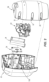
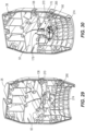
- FIG. 1 illustrates a puffer device 10.
- the puffer device 10 may be used for example to dispense pheromones in a commercial agricultural environment, such as an orchard. In other embodiments the puffer device 10 may be used to dispense pheromones, or other liquids or gases, in various other environments including non-agricultural environments.
- the puffer device 10 generally includes a cabinet 14 and an aerosol can assembly 18 that releasably couples to the cabinet 14.
- the cabinet 14 includes a front enclosure 22 and a rear enclosure 26 coupled to the front enclosure 22.
- the front and rear enclosures 22, 26 together define an overall housing for the cabinet 14, and may be made, for example of plastic or other suitable material.
- the front and rear enclosures 22, 26 are fastened or otherwise coupled together with one or more fasteners 30.
- the front and rear enclosures 22, 26 may be fastened or otherwise coupled together through the use of ultrasonic welding, or other methods that do not require fasteners.
- the front and rear enclosures 22, 26 are generally two equally shaped shells that fit together to enclose an interior of the cabinet 14. However, other embodiments may include different numbers and shapes of front and/or rear enclosures than that illustrated.
- the front enclosure 22 and/or the rear enclosure 26 may include ribs, flanges, or other structures that add structural integrity and rigidity to the cabinet 14.
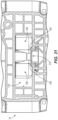
- the cabinet 14 further includes a printed circuit board 34 disposed within the interior of the cabinet 14.
- the printed circuit board 34 may include for example a sensor(s), a microcontroller(s) and/or other control device(s) for controlling operation of the puffer device 10.
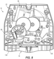
- the cabinet 14 further includes a battery holder 38 for holding one or more batteries, as well as a gear train assembly 42 for receiving commands from the printed circuit board 34 and causing a dispensing of pheromones from the aerosol can assembly 18.
- the printed circuit board 34, the battery holder 38, and the gear train assembly 42 together fit within the interior of the cabinet 14.
- the printed circuit board 34 and the battery holder 38 may be soldered or otherwise coupled together.
- the combined printed circuit board 34 and the battery holder 38 may be coupled to an interior of the front enclosure 22.
- fasteners 46 such as screws may be used to fasten the printed circuit board 34 and the battery holder 38 in place within an upper chamber 50 defined in part by the front enclosure 22.
- One or more batteries 52 may additionally be installed within the battery holder 38.
- the gear train assembly 42 includes a gear plate 54 and a motor 58 coupled to the gear plate 54 for example with fasteners 62 (e.g., screws).
- the motor 58 is coupled to a first side of the gear plate 54, and includes a driven motor shaft 66 that extends through an aperture 70 in the gear plate 54 to a second side of the gear plate 54.
- the gear plate 54 further includes bearing projections 74 on the second side of the gear plate 54 that each receive a gear 78 (e.g., a toothed gear).
- the bearing projections 74 may be pins (e.g., with knurled ends) that are inserted into the gear plate 54 and held in place.
- an additional gear 78 is coupled to driven motor shaft 66.
- the motor 58 may be coupled to the first side of the gear plate 54 and the gears 78 may be coupled to the driven motor shaft 66 and the bearing projections 74 such that rotation of the driven motor shaft 66 causes rotation of each of the gears 78 (e.g., creates a gear reduction).
- Other embodiments include various other numbers and sizes and arrangements of gears than that illustrated, as well as different types of gears than that illustrated.
- a cam 82 is coupled to and rotates with one of the gears 78.
- the cam 82 is formed integrally as a single piece with the gear 78. As illustrated in FIG. 4C , the cam 82 includes both a larger cam portion 83 and a smaller cam portion 84. As described further herein, the cam 82 is used to control and dispense pheromones from the aerosol can assembly 18.
- the gear plate 54 may be a freely floating plate that may be moved vertically up and down within the cabinet 14 (e.g., within guides defined by the front enclosure 22 and/or rear enclosure 26). Heat stakes may then be used to secure the gear plate 54 in place.
- the gear train assembly 42 further includes a switch 86 (e.g., push-activated switch).
- the switch 86 is coupled to the gear plate 54 with at least one fastener 90, although in other embodiments the switch 86 may be coupled to the gear plate through methods other than the use of fasteners.
- the smaller cam portion 84 is positioned to contact and activate the switch 86 during use of the puffer device 10.
- the gear plate 54 further includes a frame member 94 that extends from the second side of the gear plate 54 (e.g., in a direction generally parallel to the bearing projections 74).
- the frame member 94 is a solid, circular frame member defining a central aperture 98.
- the gear train assembly 42 further includes a boot 102 (e.g., a disk-like or other-shaped solid structure) and a pressing region 106 coupled to the boot 102.
- the boot 102 and pressing region 106 are coupled to the frame member 94 (e.g., along a bottom of the frame member 94).
- the pressing region 106 may be made for example of plastic, or an elastomeric material, or other material, and as illustrated in FIG. 4H may be exposed through the central aperture 98.
- the pressing region 106 is formed integrally as a single piece with the boot 102. In other embodiments the pressing region 106 is a separate member coupled to the boot 102.
- the gear train assembly 42 further includes a plunger 110 having a plunger arm 114 and a projection 118 extending from the plunger arm 114.
- the plunger 110 is a plastic or metal element that is overmolded with an elastic material.
- one end of the plunger arm 114 is coupled to one of the bearing projections 74 on the second side of the gear plate 54, such that the plunger arm 114 is rotatably coupled to the bearing projection 74 and may pivot generally along a plane that is perpendicular to a rotational axis defined by the bearing projection 74.
- Pivoting rotation of the plunger arm 114 in a downward motion causes the projection 118 to push down through the central aperture 98 and against the pressing region 106
- pivoting rotation of the plunger arm 114 in an upward motion causes the projection 118 to rise up out of the central aperture 98 and be spaced away from the pressing region 106.
- the pivoting motion of the plunger 110 is controlled by the larger cam portion 83, such that when the plunger 110 is pivoted downwardly, the projection 118 pushes against the pressing region 106 and also against the aerosol can assembly 18 (e.g., against a nozzle of the aerosol can assembly 18), causing the puffer device 10 to dispense pheromones.
- the boot 102 is made partially or entirely of a soft material (e.g., elastomeric material), whereas the pressing region 106 (e.g., a small plate) is made partially or entirely of a harder material (e.g., polycarbonate).
- a soft material e.g., elastomeric material
- the pressing region 106 e.g., a small plate
- a harder material e.g., polycarbonate
- the plunger 110 presses down it may contact the harder material of the pressing region 106 and push this material, or layer of material, down until it contacts the aerosol can assembly 18 to cause the puffer device 10 to dispense the pheromones.
- the boot 102 may be made partially or entirely of a hard material, and the pressing region 106 may be made of a softer material.
- the boot 102 may include recessed regions or channels 120 that are sized and shaped to allow the frame member 94 to fit partially within the boot 102, and/or allow the frame member 94 to shift slights within the boot 102 while still maintaining a sealed upper chamber as described below.
- the gear train assembly 42 further includes a biasing element 122 (e.g., torsion spring) that is coupled to both the gear plate 54 and to the plunger arm 114, such that the plunger arm is 114 is naturally biased in one direction (e.g., upwardly).
- a biasing element 122 e.g., torsion spring
- the biasing element 122 extends around the same bearing projection 74 upon which the plunger arm 114 is connected.
- Other embodiments include various other types of biasing elements 122 than that illustrated (e.g., tension springs, compression springs, etc.), as well as different locations for the biasing elements 122 than that illustrated.
- wires 126 may coupled (e.g., soldered) to the motor 58, the printed circuit board 34 and the battery holder 38, such that power may be supplied to the motor 58. Additionally, wires 126 may be coupled to the switch 86 and to the printed circuit board 34, such that activation of the switch 86 may be detected by the printed circuit board 34.
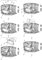
- the gear train assembly 42 may be placed within the upper chamber 50, and positioned adjacent the battery holder 38. Fasteners 130 may be used to fasten the gear train assembly 42 in place. In other embodiments, the gear train assembly 42 may be secured to the front enclosure 22 for example with heat stakes or through methods other than use of fasteners. With reference to FIGS. 5E and 5F , the rear enclosure 26 may then be fastened to the front enclosure 22, for example with the fasteners 30 (see FIG. 2 ) or via methods other than the use of fasteners.
- the front and rear enclosures 22, 26 form a seam.
- a gasket 134 e.g., elastomeric seal
- the upper chamber 50 is sealed off from the rest of the cabinet 14, and is sealed off from the aerosol can assembly 18 when the aerosol can assembly 18 is installed.
- internal ledges 138 see for example FIGS. 2 , 8 , and 9
- other structures of the front enclosure 22 and rear enclosure 26 may abut one another or overlap with one another when the front and rear enclosures 22, 26 are fastened together.
- the components within the upper chamber 50 are used to control dispensing of the pheromones from the aerosol can assembly 18.
- the puffer device 10 may determine that it is time to dispense pheromones.
- the printed circuit board 34 may receive a signal (e.g., wirelessly) that it is time to dispense, or the printed circuit board 34 may already be programmed to dispense pheromones at certain times of the day, or when certain environmental conditions are met (e.g., based on temperature, season, etc.).
- the puffer device 10 may be prevented from dispensing pheromones, for example based on surrounding environmental conditions.
- the cabinet 14 may include an on/off button or another button or buttons 140 that may be pressed manually to dispense the pheromones when desired or to otherwise control the puffer device 10.
- the printed circuit board 34 may send a signal to the motor 58, which in turn causes a rotation of the driven motor shaft 66.
- Rotation of the driven motor shaft 66 causes a rotation of the gears 78, which in turn causes a rotation of the cam 82.
- the cam 82 includes a larger cam portion 83 and a smaller cam portion 84.
- the cam 82 rotates as well.
- the cam 82 rotates in a clockwise direction, although in other embodiments the cam 82 may be arranged so as to rotate in a counterclockwise direction.
- the larger cam portion 83 is positioned to eventually rotate around and contact and push on the plunger arm 114, forcing the plunger arm 114 to rotate down. This rotational movement of the plunger arm 114 pushes the projection 118 down into the central aperture 98 and against the pressing region 106.
- the aerosol can assembly 18 is positioned directly below the pressing region 106, such that when the pressing region 106 is pressed down, it contacts the aerosol can assembly 18 (for example against a nozzle of the aerosol can assembly 18), causing the aerosol can assembly 18 to dispense pheromones.
- the upper chamber 50 is sealed off. Thus, when the pheromones are dispensed (e.g., sprayed), the upper chamber 50 remains isolated, and residue is inhibited or prevented from moving up into the upper chamber 50.
- the smaller cam portion 84 eventually comes into contact with the switch 86 (e.g., shortly after the larger cam portion 83 has pressed the plunger arm 114 down).
- a signal is sent from the switch 86 to the printed circuit board 34.
- the printed circuit board 34 stops the motor 58 for a predetermined period of time. For example, in some embodiments the motor 58 is stopped for 1.5 seconds. In other embodiments the motor 58 is stopped for 1 second, or 2 seconds, or between 1-2 seconds. Other embodiments include different values and ranges.
- the gears 78 stop rotating, and the plunger arm 114 remains pressed down, so that the pheromones continue to be dispensed from the aerosol can assembly 18 for a predetermined period of time.
- the printed circuit board 34 then starts the motor 58 again, and the gears 78 again begin to rotate.
- Rotation of the gears 78 causes the cam 82 (including both the larger cam portion 83 and the smaller cam portion 84) to rotate, and for the larger cam portion 83 to move out of contact with the plunger arm 114 and the smaller cam portion 84 to move out of contact with the switch 86.
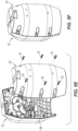
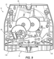
- the biasing element 122 raises the plunger arm 114 back up ( FIG. 8 ).
- the switch 86 is not provided. Rather, the cam 82 itself remains in contact with and pressed down long enough on the plunger arm 114 to emit a sufficient amount of pheromones from the aerosol can assembly 18 before the cam 82 is rotated out of contact with the plunger arm 114.
- both the larger cam portion 83 and the smaller cam portion 84 are both positioned on a single cam 82, in other embodiments the larger cam portion 83 and the smaller cam portion 84 may each be positioned on separate cams 82 (e.g., coupled to different gears 78 within the cabinet 14).
- the use of the cam 82 described above may provide for consistent strokes of the plunger arm 114 (e.g., causing the projection 118 to move down the same distance with each stroke), and thus consistent emission of pheromones.
- the motor 58 does not need to reverse direction to stop emission of the pheromones. Rather, the motor 58 may continue to operate in one direction, causing the cam 82 to continue to rotate (e.g., clockwise) until a further emission of pheromones is needed. Because of this directional motion, the life of the motor 58 may be extended, and stalling of the motor 58 may be prevented or inhibited.
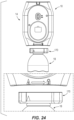
- the aerosol can assembly 18 includes an aerosol can 142 that contains the pheromones described above.
- the aerosol can 142 includes a top end 146 with a rim 150 (e.g., a circumferential rim) that defines an opening.
- a valve 154 is coupled to the rim 150 and extends across the opening.
- the valve 154 includes a central, raised section 158, as well as a separate, outer raised lip 162 that is crimped onto the rim 150.
- a nozzle 166 (which may include an actuator) extends through the valve 154 (e.g., centrally through the central, raised section 158). Pheromones from the aerosol can 142 are released through the nozzle 166, for example by pressing down on or otherwise moving a portion of the nozzle 166.
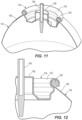
- the aerosol can assembly 18 further includes an adapter 170.
- the adapter 170 includes a first end 174 and an opposite, second end 176.
- the first end 174 includes a first set of projections (e.g., arms) 178 that generally form a V-shaped, U-shaped, or other shaped cavity or space there between.
- the nozzle 166 extends between the projections 178 within this cavity or space.
- the adapter 170 replaces the need for a cap for the aerosol can 142.
- each of the projections 178 includes a generally rounded surface 182 along a portion of the projection 178, as well as a generally flat, angled surface 186 along another portion of the projection 178.
- Other embodiments include different shapes and sizes for the projections 178 than that illustrated.
- the second end 176 includes a second set of projections (e.g., flexible arms) 190 that also generally form a V-shaped, U-shaped, or other-shaped cavity or space there between.
- each of the projections 190 includes generally rounded surfaces 194 at ends of the projections 190.
- the adapter 170 further includes a lower attachment region 198 that is disposed generally between the first set of projections 178 and the second set of projections 190, and extends below the first set of projections 178 and the second set of projections 190.
- the lower attachment region 198 is generally a circumferential ring that defines a central opening 202.
- the lower attachment region 198 includes at least one lower, radially outwardly projecting portion 206 (e.g., tab, rib, etc.).
- the adapter 170 may initially be coupled to the valve 154 by pressing the lower attachment region 198 of the adapter 170 down over the central, raised section 158, until the projecting portion or portions 206 generally snap underneath or are otherwise positioned adjacent or underneath the lip 162 of the valve 154 and the rim 150 of the aerosol can 142.
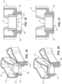
- the lock 210 is a generally ring-like structure that is sized and shaped to fit within the central opening 202 formed by the lower attachment region 198 of the adapter 170.
- the lock 210 includes a body 214 that defines a central opening 218.
- the central opening 218 is sized and shaped to accommodate and receive the central, raised section 158 of the valve 154.
- the body 214 includes a series of tapered ribs 222 spaced circumferentially around the body 214.
- the ribs 222 taper axially, such that along a top region 226 of the lock 210 the ribs 222 extend radially outwardly farther than along a lower region 230 of the lock 210.
- the lock 210 further includes an elongate projecting tab 234.
- the tab 234 has a generally T-shaped structure at its distal end that includes a first arm 238 with a first engagement surface 242 and a second arm 246 with a second engagement surface 250.
- Other embodiments include different sizes and shapes for the tab 234 than that shown.
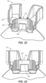
- the adapter 170 includes a corresponding first engagement surface 254 and a second engagement surface 258 (e.g., each disposed on the lower attachment region 198).
- the first engagement surface 242 of the tab 234 is directly below the first engagement surface 254 of the adapter 170, and the second engagement surface 250 of the tab 234 is directly below the second engagement surface 258 of the adapter 170.
- This positioning of the tab 234 and the engagement surfaces 242, 250, 254, 258 may be achieved by pressing the lock 210 directly down onto the adapter 170 until the tab 234 snaps in place.
- the ribs 222 of the lock 210 when the lock 210 is being pressed down onto the adapter 170, the ribs 222 of the lock 210 also engage and press radially outwardly against an inner surface 262 of the lower attachment region 198 (e.g., due to the tapered nature of the ribs 222), forcing the projecting portions 206 further radially outwardly to lock the adapter 170 in place. As illustrated in FIGS.
- the lock 210 when the distal end of the tab 234 has snapped beneath the first and second engagement surfaces 254, 258 of the adapter 170, the lock 210 may be considered to be in a minimum locked position, with the ribs 222 pressing the projecting portions 206 radially outwardly and the tab 234 acting as a stop to inhibit or prevent the lock 210 from being raised up axially. With reference to FIGS. 20-23 , the lock 210 may be pressed down even farther until a maximum locked position is reached. In this maximum locked position illustrated in FIGS. 20-23 , the lock 210 extends entirely or substantially entirely through the central opening 202, with the central, raised section 158 extending up through the central opening 218 of the lock 210.
- the aerosol can assembly 18 may be coupled to the cabinet 14 via a rotational movement of the aerosol can assembly 18 within the cabinet 14.
- the cabinet 14 and/or the adapter 170 may include a marking or markings indicating in initial insertion position of the adapter 170 into the cabinet 14. Other embodiments do not include such markings.
- the aerosol can assembly 18 may first be pressed up linearly into the cabinet 14.
- the cabinet 14 may include one or more internal ledges 266 or other structures that create a keyway for insertion of the adapter 170.
- the adapter 170 may only be inserted into the cabinet 14 if the adapter 170 is first in a predefined rotational position relative to the cabinet 14.
- the adapter 170 may be limited from further insertion by the internal ledges 138 described above that define the upper chamber 50.
- the adapter 170 thus sits within a lower chamber 270 (e.g., below the upper chamber 50 described above).
- the aerosol can assembly 18, including the adapter 170 may then be rotated (e.g., 90 degrees or any other predefined angle) within the lower chamber 270 to a locked position.
- the cabinet 14 may include a locking tab 274 positioned within the lower chamber 270 (e.g., within the rear enclosure 26).
- the adapter 170 when the adapter 170 is rotated to the locked position, the generally rounded surface 194 of one of the projections 190 on the first end 174 of the adapter 170 slides and snaps up and over the locking tab 274, such that the locking tab 274 is thereby positioned between the two projections 190.
- the projections 190 are generally flexible, thus facilitating flexing and movement.
- the adapter 170 in the locked position the adapter 170 is generally inhibited from easily rotating again within the lower chamber 270.
- the adapter 170 is rotated hard enough in an opposite direction to force the projection 190 back up and over the locking tab 274. While a single locking tab 274 on the cabinet 14 and two projections 190 on the adapter 170 are illustrated, various other snap-fit engagements may also be used to releasably couple the adapter 170 (and the aerosol can assembly 18) overall to the cabinet 14.
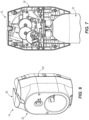
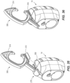
- the puffer device 10 may include a keyed region to couple one or more different hanging devices to hang the puffer device 10 within an agricultural environment (e.g., from a tree branch, pole, etc.).
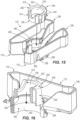
- the puffer device 10 includes a keyed region 278 generally along a top of the cabinet 14.
- the keyed region 278 includes a rib 282 defining an aperture 286.
- the rib 282 and the aperture 286 are located generally centrally along the top of the cabinet 14, although in other embodiments they may be located at other locations on the cabinet 14.
- the keyed region 278 further includes channels 290 disposed on opposite sides of the rib 282.
- the channels 290 have dovetail cross-sectional shapes, although other embodiments include other shapes (e.g., generally circular, oval, etc.). Additionally, other embodiments may include different numbers of apertures and/or channels than that illustrated.
- the puffer device 10 may include a first hanging device 294 that includes a hook region 298 that passes through the aperture 286.
- the first hanging device 294 may further include a second hook region 302 that hooks over a tree branch, pole, etc., so as to hang the puffer device 10.
- the puffer device 10 may further include a second hanging device 306 that includes a channel-engaging member 310 that slides into and is secured within one of the channels 290 of the keyed region 278.
- the channel-engaging member 310 has generally a dovetail cross-sectional shape that corresponds with the dovetail shape of the channel 290.
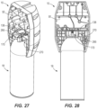
- the second hanging device 306 further includes a region that passes through the aperture 286, and/or a region that snaps onto the rib 282, to further secure the second hanging device 306 to the cabinet 14. As illustrated in FIGS. 35 and 36 , the second hanging device 306 further includes a larger hook region 314 that hooks over a tree branch, pole, or other object, etc., so as to hang the puffer device 10.
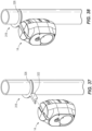
- the puffer device 10 may further include a third hanging device 318 that includes a channel-engaging member 322 that slides into and is secured within one of the channels 290 of the keyed region 278.
- the channel-engaging member 322 has a dovetail cross-sectional shape that corresponds with the dovetail shape of the channel 290.
- the cabinet 14 is secured to the third hanging device 318 and is vertically supported by the third hanging device 318.
- the third hanging device 318 further includes a region that passes through the aperture 286, and/or a region that snaps onto the rib 282, to further secure the third hanging device 318 to the cabinet 14. As illustrated in FIGS. 37 and 38 , the third hanging device 318 further includes a ring region 326 that snaps or otherwise engages around a pole 330.
- the puffer device 10 may include various numbers of different hanging devices that all may be coupled to the same keyed region 278 on the cabinet 14.
- the different hanging devices may have shapes and features other than that illustrated.
- the cabinet 14 may include more than one keyed region 278.
- the cabinet 14 may include a first keyed region 278 along a top of the cabinet, and a second keyed region 278 along a side of the cabinet 14.
- Different hanging devices may be coupled to the various keyed regions.
- the keyed region or regions 278 may be used to receive and support devices other than hanging devices.
Landscapes
- Life Sciences & Earth Sciences (AREA)
- Engineering & Computer Science (AREA)
- Wood Science & Technology (AREA)
- Environmental Sciences (AREA)
- Microelectronics & Electronic Packaging (AREA)
- Biodiversity & Conservation Biology (AREA)
- Ecology (AREA)
- Forests & Forestry (AREA)
- Health & Medical Sciences (AREA)
- Zoology (AREA)
- Pest Control & Pesticides (AREA)
- Insects & Arthropods (AREA)
- Birds (AREA)
- General Health & Medical Sciences (AREA)
- Toxicology (AREA)
- Chemical & Material Sciences (AREA)
- Dispersion Chemistry (AREA)
- Mechanical Engineering (AREA)
- Botany (AREA)
- Catching Or Destruction (AREA)
- Connection Of Motors, Electrical Generators, Mechanical Devices, And The Like (AREA)
- Electric Connection Of Electric Components To Printed Circuits (AREA)
- Nozzles (AREA)
- Containers And Packaging Bodies Having A Special Means To Remove Contents (AREA)
Claims (15)
- Dispositif de pulvérisation (10) comprenant :un boîtier (14) comportant une carte de circuit imprimé (34) et un ensemble formant train d'engrenages (42) couplé à la carte de circuit imprimé (34), l'ensemble formant train d'engrenages (42) incluant un moteur (58) et un engrenage (78) entraîné par le moteur (58), l'ensemble formant train d'engrenages ayant en outre une came (82) couplée à l'engrenage (78), le boîtier (14) incluant en outre un piston (110) configuré pour être contacté et entraîné par la came (82) ; et caractérisé parun ensemble formant bombe aérosol (18) configuré pour être couplé de manière amovible au boîtier (14), dans lequel le mouvement du piston (110) est configuré pour distribuer un produit à partir de l'ensemble formant bombe aérosol (18).
- Dispositif de pulvérisation selon la revendication 1, dans lequel la came (82) est formée d'une seule pièce avec l'engrenage (78).
- Dispositif de pulvérisation selon la revendication 1, dans lequel la came (82) inclut une première partie de came (83) et une deuxième partie de came (84) séparée.
- Dispositif de pulvérisation selon la revendication 3, dans lequel la première partie de came (83) est configurée pour tourner avec l'engrenage (78) et entrer en contact avec le piston (110) pour provoquer un mouvement de pivotement du piston (110).
- Dispositif de pulvérisation selon la revendication 4, comprenant en outre un interrupteur (86), dans lequel la deuxième partie de came (84) est configurée pour tourner avec l'engrenage (78) et pour entrer en contact avec l'interrupteur (86) et provoquer l'envoi d'un signal à la carte de circuit imprimé (34).
- Dispositif de pulvérisation selon la revendication 5, dans lequel la deuxième partie de came (84) est configurée pour entrer en contact avec l'interrupteur (86) après que la première partie de came (83) soit entrée en contact avec le piston (110).
- Dispositif de pulvérisation selon la revendication 5, dans lequel la carte de circuit imprimé (34) est configurée pour arrêter le moteur (58) pendant une période de temps prédéterminée après avoir reçu le signal.
- Dispositif de pulvérisation selon la revendication 1, dans lequel l'ensemble formant train d'engrenages (42) inclut une plaque d'engrenages (54) ayant un élément de châssis (94), dans lequel l'engrenage (78) est couplé à la plaque d'engrenages (54), dans lequel une embase (102) est couplée à l'élément de châssis (94), et dans lequel une région de pression (106) est couplée à l'embase (102).
- Dispositif de pulvérisation selon la revendication 8, dans lequel le piston (110) inclut une projection (118), dans lequel le piston (110) est configuré pour tourner de manière à ce que la projection (118) entre en contact et appuie contre la région de pression (106) pour déplacer la région de pression (106) en contact avec l'ensemble formant bombe aérosol (18).
- Dispositif de pulvérisation selon la revendication 1, dans lequel l'ensemble formant train d'engrenages (42) inclut une plaque d'engrenages (54) et une projection de roulement (74) s'étendant depuis la plaque d'engrenages (54), dans lequel le piston (110) est couplé de manière rotative à la projection de roulement (74).
- Dispositif de pulvérisation selon la revendication 10, dans lequel le piston (110) inclut un bras de piston (114) et une projection (118) s'étendant à partir du bras de piston (114).
- Dispositif de pulvérisation selon la revendication 1, dans lequel le boîtier (14) inclut une enceinte avant (22) et une enceinte arrière (26) couplée à l'enceinte avant (22), dans lequel l'enceinte avant (22) et l'enceinte arrière (26) définissent une chambre supérieure scellée (50) à l'intérieur du boîtier (14).
- Dispositif de pulvérisation selon la revendication 1, dans lequel le boîtier (14) inclut une chambre supérieure scellée (50), dans lequel la carte de circuit imprimé (34) et l'ensemble formant train d'engrenages (42) sont chacun disposés dans la chambre supérieure scellée (50).
- Dispositif de pulvérisation selon la revendication 1, dans lequel l'ensemble formant bombe aérosol (18) inclut une bombe aérosol (142), un adaptateur (170) couplé à la bombe aérosol (142), et un verrou (210) couplé à l'adaptateur (170), dans lequel l'ensemble formant bombe aérosol (18) est configuré pour être couplé de manière libérable au boîtier (14) par une rotation de l'adaptateur (170) à l'intérieur du boîtier (14).
- Dispositif de pulvérisation selon la revendication 1, dans lequel le boîtier (14) inclut un logement (22, 26), dans lequel le logement inclut une région clavettée (278) le long d'un côté extérieur du logement (22, 26), dans lequel le dispositif de pulvérisation inclut en outre un dispositif d'accrochage (294) configuré pour être couplé à la région clavettée (278).
Priority Applications (3)
| Application Number | Priority Date | Filing Date | Title |
|---|---|---|---|
| EP25210188.6A EP4656552A3 (fr) | 2019-04-03 | 2020-02-04 | Dispositif de soufflerie |
| EP24161577.2A EP4353623B1 (fr) | 2019-04-03 | 2020-02-04 | Dispositif de soufflerie |
| SI202030409T SI3946552T1 (sl) | 2019-04-03 | 2020-02-04 | Naprava za napihovanje |
Applications Claiming Priority (2)
| Application Number | Priority Date | Filing Date | Title |
|---|---|---|---|
| US201962828636P | 2019-04-03 | 2019-04-03 | |
| PCT/US2020/016524 WO2020205054A1 (fr) | 2019-04-03 | 2020-02-04 | Dispositif de soufflerie |
Related Child Applications (3)
| Application Number | Title | Priority Date | Filing Date |
|---|---|---|---|
| EP25210188.6A Division EP4656552A3 (fr) | 2019-04-03 | 2020-02-04 | Dispositif de soufflerie |
| EP24161577.2A Division EP4353623B1 (fr) | 2019-04-03 | 2020-02-04 | Dispositif de soufflerie |
| EP24161577.2A Division-Into EP4353623B1 (fr) | 2019-04-03 | 2020-02-04 | Dispositif de soufflerie |
Publications (3)
| Publication Number | Publication Date |
|---|---|
| EP3946552A1 EP3946552A1 (fr) | 2022-02-09 |
| EP3946552A4 EP3946552A4 (fr) | 2023-03-15 |
| EP3946552B1 true EP3946552B1 (fr) | 2024-04-10 |
Family
ID=72661824
Family Applications (3)
| Application Number | Title | Priority Date | Filing Date |
|---|---|---|---|
| EP24161577.2A Active EP4353623B1 (fr) | 2019-04-03 | 2020-02-04 | Dispositif de soufflerie |
| EP20782871.6A Active EP3946552B1 (fr) | 2019-04-03 | 2020-02-04 | Dispositif de soufflerie |
| EP25210188.6A Pending EP4656552A3 (fr) | 2019-04-03 | 2020-02-04 | Dispositif de soufflerie |
Family Applications Before (1)
| Application Number | Title | Priority Date | Filing Date |
|---|---|---|---|
| EP24161577.2A Active EP4353623B1 (fr) | 2019-04-03 | 2020-02-04 | Dispositif de soufflerie |
Family Applications After (1)
| Application Number | Title | Priority Date | Filing Date |
|---|---|---|---|
| EP25210188.6A Pending EP4656552A3 (fr) | 2019-04-03 | 2020-02-04 | Dispositif de soufflerie |
Country Status (8)
| Country | Link |
|---|---|
| US (2) | US11117734B2 (fr) |
| EP (3) | EP4353623B1 (fr) |
| CN (2) | CN113710090B (fr) |
| ES (2) | ES3058384T3 (fr) |
| PL (2) | PL3946552T3 (fr) |
| PT (2) | PT4353623T (fr) |
| SI (1) | SI3946552T1 (fr) |
| WO (1) | WO2020205054A1 (fr) |
Families Citing this family (1)
| Publication number | Priority date | Publication date | Assignee | Title |
|---|---|---|---|---|
| ES3058384T3 (es) * | 2019-04-03 | 2026-03-10 | Suterra Llc | Dispositivo pulverizador |
Family Cites Families (38)
| Publication number | Priority date | Publication date | Assignee | Title |
|---|---|---|---|---|
| US3584766A (en) * | 1969-12-10 | 1971-06-15 | Charles M Hart | Spray dispenser having a capacitor discharge timer |
| US3710985A (en) * | 1970-11-09 | 1973-01-16 | First National Bank Of Chicago | Dispenser for providing warm lather for shaving |
| US3732509A (en) * | 1971-01-18 | 1973-05-08 | Syncro Mist Controls Inc | Apparatus to provide periodic movement |
| US3739944A (en) * | 1972-05-25 | 1973-06-19 | Westinghouse Electric Corp | Automatic periodically actuated spray dispenser |
| GB1484010A (en) * | 1973-10-19 | 1977-08-24 | Wellcome Found | Mechanisms for intermittently actuating the discharge valve of a pressurised dispensing container |
| US3997083A (en) * | 1974-07-15 | 1976-12-14 | Dazey Products Company | Shaving lather heater and dispenser having heat storing element |
| US4063664A (en) * | 1976-09-13 | 1977-12-20 | The Risdon Manufacturing Company | Device for indicating when automatic, periodic operation has emptied an aerosol container |
| GB1599153A (en) * | 1976-10-12 | 1981-09-30 | Strattwell Developments Ltd | Fluid dispenser |
| US5249718A (en) * | 1992-03-16 | 1993-10-05 | Technical Concepts | Automatic pump-type spray dispenser |
| CN2146310Y (zh) * | 1993-01-07 | 1993-11-17 | 四川电子生产工程研究开发中心 | 定时定量自动喷雾器 |
| US5358147A (en) * | 1993-09-02 | 1994-10-25 | S. C. Johnson & Son, Inc. | Spray dispensing package |
| JP4204727B2 (ja) * | 1999-12-27 | 2009-01-07 | 東洋エアゾール工業株式会社 | エアゾール容器のバルブ開閉機構 |
| US6293442B1 (en) * | 2000-05-16 | 2001-09-25 | Girard D. Mollayan | Timed aerosol spray dispenser |
| US6415957B1 (en) | 2000-11-27 | 2002-07-09 | S. C. Johnson & Son, Inc. | Apparatus for dispensing a heated post-foaming gel |
| US7222760B1 (en) | 2002-02-07 | 2007-05-29 | Chyuan-Feng Tsay | Driving mechanism for fragrance dispenser |
| US7648083B2 (en) | 2003-12-18 | 2010-01-19 | S.C. Johnson & Son, Inc. | Power sprayer |
| US7651009B2 (en) * | 2004-08-16 | 2010-01-26 | Warner Lambert Company Llc | Liquid dispensing device |
| CN101111449A (zh) * | 2005-01-10 | 2008-01-23 | 海索技术有限责任公司 | 门把手消毒系统及阀连接装置 |
| CA2507914A1 (fr) * | 2005-05-19 | 2006-11-19 | Gotohti.Com Inc. | Pompe a piston frangible |
| CA2623755A1 (fr) * | 2005-09-23 | 2007-04-12 | Afa Polytek B.V. | Procede et ensemble de distribution de produit d'un recipient a memoire de forme |
| CN200988016Y (zh) * | 2006-07-21 | 2007-12-12 | 宁波宁兴国贸实业有限公司 | 一种自动喷雾器 |
| GB0623052D0 (en) * | 2006-11-18 | 2006-12-27 | Reckitt Benckiser Uk Ltd | An assembly |
| US8469244B2 (en) * | 2007-08-16 | 2013-06-25 | S.C. Johnson & Son, Inc. | Overcap and system for spraying a fluid |
| KR101434910B1 (ko) * | 2008-06-13 | 2014-08-28 | 배성태 | 향기분사장치 |
| US8162276B2 (en) * | 2008-09-29 | 2012-04-24 | Clipsy, Llc | Rotary joint assembly and combination clip-hook and jewelry piece employing the same |
| US8240508B2 (en) * | 2008-12-29 | 2012-08-14 | Gojo Industries, Inc. | Low cost radio frequency identification (RFID) dispensing systems |
| US8453883B2 (en) * | 2009-03-18 | 2013-06-04 | Bigfoot Holdings Ltd. | Personal defense spray device |
| DE102010023562A1 (de) * | 2010-06-09 | 2011-12-15 | Solon Se | Tragplatte zur Lagerung von Solarmodulen auf einem Flachsubstrat und Tragplattenfeld |
| US9833533B2 (en) * | 2012-09-07 | 2017-12-05 | S.C. Johnson & Son, Inc. | Product dispensing system |
| US9894852B2 (en) | 2013-01-08 | 2018-02-20 | Semiosbio Technologies Inc. | Monitoring and control systems for the agricultural industry |
| EA026806B1 (ru) * | 2013-01-10 | 2017-05-31 | Эль И Д, С.А.У. | Освежитель воздуха |
| US10010898B2 (en) * | 2013-03-15 | 2018-07-03 | S. C. Johnson & Son, Inc. | Dispensing systems with wave sensors |
| CN105188953B (zh) * | 2013-05-08 | 2018-06-22 | 固瑞克明尼苏达有限公司 | 用于手持式喷涂装置的涂料罐适配器 |
| US20150083755A1 (en) * | 2013-09-26 | 2015-03-26 | Alex Mecker | Dispensing System with Bracket |
| US9205167B2 (en) * | 2014-05-02 | 2015-12-08 | Kimberly-Clark Worldwide, Inc. | Dispenser system for aerosol and non-aerosol products |
| CN206009098U (zh) * | 2016-07-28 | 2017-03-15 | 深圳市亘诺科技有限公司 | 便于补充水分的雾化器 |
| CN207426374U (zh) * | 2017-11-06 | 2018-05-29 | 江西铭德电器有限公司 | 一种新型挂钩式换向器 |
| ES3058384T3 (es) * | 2019-04-03 | 2026-03-10 | Suterra Llc | Dispositivo pulverizador |
-
2020
- 2020-02-04 ES ES24161577T patent/ES3058384T3/es active Active
- 2020-02-04 ES ES20782871T patent/ES2980964T3/es active Active
- 2020-02-04 PL PL20782871.6T patent/PL3946552T3/pl unknown
- 2020-02-04 CN CN202080026728.5A patent/CN113710090B/zh active Active
- 2020-02-04 PT PT241615772T patent/PT4353623T/pt unknown
- 2020-02-04 WO PCT/US2020/016524 patent/WO2020205054A1/fr not_active Ceased
- 2020-02-04 CN CN202310025227.0A patent/CN116019078A/zh active Pending
- 2020-02-04 PT PT207828716T patent/PT3946552T/pt unknown
- 2020-02-04 EP EP24161577.2A patent/EP4353623B1/fr active Active
- 2020-02-04 US US16/781,368 patent/US11117734B2/en active Active
- 2020-02-04 SI SI202030409T patent/SI3946552T1/sl unknown
- 2020-02-04 EP EP20782871.6A patent/EP3946552B1/fr active Active
- 2020-02-04 EP EP25210188.6A patent/EP4656552A3/fr active Pending
- 2020-02-04 PL PL24161577.2T patent/PL4353623T3/pl unknown
-
2021
- 2021-08-09 US US17/397,080 patent/US11820582B2/en active Active
Also Published As
| Publication number | Publication date |
|---|---|
| EP4656552A2 (fr) | 2025-12-03 |
| EP4656552A3 (fr) | 2026-01-14 |
| EP4353623B1 (fr) | 2025-11-19 |
| US11117734B2 (en) | 2021-09-14 |
| US11820582B2 (en) | 2023-11-21 |
| EP3946552A1 (fr) | 2022-02-09 |
| PT3946552T (pt) | 2024-05-23 |
| CN113710090B (zh) | 2023-01-31 |
| EP4353623A3 (fr) | 2024-09-11 |
| PT4353623T (pt) | 2025-12-23 |
| CN113710090A (zh) | 2021-11-26 |
| PL4353623T3 (pl) | 2026-02-02 |
| SI3946552T1 (sl) | 2025-03-31 |
| PL3946552T3 (pl) | 2024-07-22 |
| US20200317428A1 (en) | 2020-10-08 |
| EP4353623A2 (fr) | 2024-04-17 |
| WO2020205054A1 (fr) | 2020-10-08 |
| EP3946552A4 (fr) | 2023-03-15 |
| ES3058384T3 (es) | 2026-03-10 |
| CN116019078A (zh) | 2023-04-28 |
| ES2980964T3 (es) | 2024-10-03 |
| US20210362940A1 (en) | 2021-11-25 |
Similar Documents
| Publication | Publication Date | Title |
|---|---|---|
| JP5364094B2 (ja) | 流体をスプレーするためのオーバーキャップ及びシステム | |
| US20080290113A1 (en) | Actuator cap for a spray device | |
| US6517009B2 (en) | Automatic spray dispenser | |
| CN102015484B (zh) | 挥发性材料散放器的控制设备 | |
| US20040155056A1 (en) | Spray dispenser | |
| US8381951B2 (en) | Overcap for a spray device | |
| US20080290120A1 (en) | Actuator cap for a spray device | |
| KR20020025064A (ko) | 자동 에어로졸 분무기 | |
| EP3946552B1 (fr) | Dispositif de soufflerie | |
| CA2464723A1 (fr) | Valve de distribution intermittente d'aerosol | |
| KR20040063787A (ko) | 에어로졸 분배 밸브 | |
| US4243161A (en) | Continuous spray button | |
| WO2005072059A2 (fr) | Pulverisateur | |
| US20060255075A1 (en) | Trigger sprayer with venting membrane in protective housing cavity | |
| GB2580942A (en) | Aerosol dispensing system | |
| WO2005094492A2 (fr) | Pulverisateur a gachette a membrane de ventilation |
Legal Events
| Date | Code | Title | Description |
|---|---|---|---|
| STAA | Information on the status of an ep patent application or granted ep patent |
Free format text: STATUS: THE INTERNATIONAL PUBLICATION HAS BEEN MADE |
|
| PUAI | Public reference made under article 153(3) epc to a published international application that has entered the european phase |
Free format text: ORIGINAL CODE: 0009012 |
|
| STAA | Information on the status of an ep patent application or granted ep patent |
Free format text: STATUS: REQUEST FOR EXAMINATION WAS MADE |
|
| 17P | Request for examination filed |
Effective date: 20211015 |
|
| AK | Designated contracting states |
Kind code of ref document: A1 Designated state(s): AL AT BE BG CH CY CZ DE DK EE ES FI FR GB GR HR HU IE IS IT LI LT LU LV MC MK MT NL NO PL PT RO RS SE SI SK SM TR |
|
| DAV | Request for validation of the european patent (deleted) | ||
| DAX | Request for extension of the european patent (deleted) | ||
| RIC1 | Information provided on ipc code assigned before grant |
Ipc: B65D 83/38 20060101ALI20221109BHEP Ipc: B65D 83/26 20060101ALI20221109BHEP Ipc: A01M 29/12 20110101AFI20221109BHEP |
|
| REG | Reference to a national code |
Ref country code: DE Ref legal event code: R079 Free format text: PREVIOUS MAIN CLASS: H99Z9999999999 Ipc: A01M0029120000 Ref country code: DE Ref legal event code: R079 Ref document number: 602020028846 Country of ref document: DE Free format text: PREVIOUS MAIN CLASS: H99Z9999999999 Ipc: A01M0029120000 |
|
| A4 | Supplementary search report drawn up and despatched |
Effective date: 20230215 |
|
| RIC1 | Information provided on ipc code assigned before grant |
Ipc: B65D 83/38 20060101ALI20230209BHEP Ipc: B65D 83/26 20060101ALI20230209BHEP Ipc: A01M 29/12 20110101AFI20230209BHEP |
|
| P01 | Opt-out of the competence of the unified patent court (upc) registered |
Effective date: 20230527 |
|
| GRAP | Despatch of communication of intention to grant a patent |
Free format text: ORIGINAL CODE: EPIDOSNIGR1 |
|
| STAA | Information on the status of an ep patent application or granted ep patent |
Free format text: STATUS: GRANT OF PATENT IS INTENDED |
|
| INTG | Intention to grant announced |
Effective date: 20231027 |
|
| GRAS | Grant fee paid |
Free format text: ORIGINAL CODE: EPIDOSNIGR3 |
|
| GRAA | (expected) grant |
Free format text: ORIGINAL CODE: 0009210 |
|
| STAA | Information on the status of an ep patent application or granted ep patent |
Free format text: STATUS: THE PATENT HAS BEEN GRANTED |
|
| AK | Designated contracting states |
Kind code of ref document: B1 Designated state(s): AL AT BE BG CH CY CZ DE DK EE ES FI FR GB GR HR HU IE IS IT LI LT LU LV MC MK MT NL NO PL PT RO RS SE SI SK SM TR |
|
| REG | Reference to a national code |
Ref country code: GB Ref legal event code: FG4D |
|
| REG | Reference to a national code |
Ref country code: CH Ref legal event code: EP |
|
| REG | Reference to a national code |
Ref country code: DE Ref legal event code: R096 Ref document number: 602020028846 Country of ref document: DE |
|
| REG | Reference to a national code |
Ref country code: IE Ref legal event code: FG4D |
|
| REG | Reference to a national code |
Ref country code: PT Ref legal event code: SC4A Ref document number: 3946552 Country of ref document: PT Date of ref document: 20240523 Kind code of ref document: T Free format text: AVAILABILITY OF NATIONAL TRANSLATION Effective date: 20240516 |
|
| REG | Reference to a national code |
Ref country code: GR Ref legal event code: EP Ref document number: 20240401431 Country of ref document: GR Effective date: 20240716 |
|
| REG | Reference to a national code |
Ref country code: NL Ref legal event code: FP |
|
| REG | Reference to a national code |
Ref country code: LT Ref legal event code: MG9D |
|
| REG | Reference to a national code |
Ref country code: ES Ref legal event code: FG2A Ref document number: 2980964 Country of ref document: ES Kind code of ref document: T3 Effective date: 20241003 |
|
| PG25 | Lapsed in a contracting state [announced via postgrant information from national office to epo] |
Ref country code: IS Free format text: LAPSE BECAUSE OF FAILURE TO SUBMIT A TRANSLATION OF THE DESCRIPTION OR TO PAY THE FEE WITHIN THE PRESCRIBED TIME-LIMIT Effective date: 20240810 |
|
| PG25 | Lapsed in a contracting state [announced via postgrant information from national office to epo] |
Ref country code: BG Free format text: LAPSE BECAUSE OF FAILURE TO SUBMIT A TRANSLATION OF THE DESCRIPTION OR TO PAY THE FEE WITHIN THE PRESCRIBED TIME-LIMIT Effective date: 20240410 |
|
| PG25 | Lapsed in a contracting state [announced via postgrant information from national office to epo] |
Ref country code: FI Free format text: LAPSE BECAUSE OF FAILURE TO SUBMIT A TRANSLATION OF THE DESCRIPTION OR TO PAY THE FEE WITHIN THE PRESCRIBED TIME-LIMIT Effective date: 20240410 Ref country code: HR Free format text: LAPSE BECAUSE OF FAILURE TO SUBMIT A TRANSLATION OF THE DESCRIPTION OR TO PAY THE FEE WITHIN THE PRESCRIBED TIME-LIMIT Effective date: 20240410 |
|
| PG25 | Lapsed in a contracting state [announced via postgrant information from national office to epo] |
Ref country code: LV Free format text: LAPSE BECAUSE OF FAILURE TO SUBMIT A TRANSLATION OF THE DESCRIPTION OR TO PAY THE FEE WITHIN THE PRESCRIBED TIME-LIMIT Effective date: 20240410 |
|
| PG25 | Lapsed in a contracting state [announced via postgrant information from national office to epo] |
Ref country code: NO Free format text: LAPSE BECAUSE OF FAILURE TO SUBMIT A TRANSLATION OF THE DESCRIPTION OR TO PAY THE FEE WITHIN THE PRESCRIBED TIME-LIMIT Effective date: 20240710 Ref country code: LV Free format text: LAPSE BECAUSE OF FAILURE TO SUBMIT A TRANSLATION OF THE DESCRIPTION OR TO PAY THE FEE WITHIN THE PRESCRIBED TIME-LIMIT Effective date: 20240410 Ref country code: IS Free format text: LAPSE BECAUSE OF FAILURE TO SUBMIT A TRANSLATION OF THE DESCRIPTION OR TO PAY THE FEE WITHIN THE PRESCRIBED TIME-LIMIT Effective date: 20240810 Ref country code: HR Free format text: LAPSE BECAUSE OF FAILURE TO SUBMIT A TRANSLATION OF THE DESCRIPTION OR TO PAY THE FEE WITHIN THE PRESCRIBED TIME-LIMIT Effective date: 20240410 Ref country code: FI Free format text: LAPSE BECAUSE OF FAILURE TO SUBMIT A TRANSLATION OF THE DESCRIPTION OR TO PAY THE FEE WITHIN THE PRESCRIBED TIME-LIMIT Effective date: 20240410 Ref country code: BG Free format text: LAPSE BECAUSE OF FAILURE TO SUBMIT A TRANSLATION OF THE DESCRIPTION OR TO PAY THE FEE WITHIN THE PRESCRIBED TIME-LIMIT Effective date: 20240410 Ref country code: RS Free format text: LAPSE BECAUSE OF FAILURE TO SUBMIT A TRANSLATION OF THE DESCRIPTION OR TO PAY THE FEE WITHIN THE PRESCRIBED TIME-LIMIT Effective date: 20240710 |
|
| REG | Reference to a national code |
Ref country code: DE Ref legal event code: R097 Ref document number: 602020028846 Country of ref document: DE |
|
| PG25 | Lapsed in a contracting state [announced via postgrant information from national office to epo] |
Ref country code: DK Free format text: LAPSE BECAUSE OF FAILURE TO SUBMIT A TRANSLATION OF THE DESCRIPTION OR TO PAY THE FEE WITHIN THE PRESCRIBED TIME-LIMIT Effective date: 20240410 |
|
| PG25 | Lapsed in a contracting state [announced via postgrant information from national office to epo] |
Ref country code: EE Free format text: LAPSE BECAUSE OF FAILURE TO SUBMIT A TRANSLATION OF THE DESCRIPTION OR TO PAY THE FEE WITHIN THE PRESCRIBED TIME-LIMIT Effective date: 20240410 |
|
| PG25 | Lapsed in a contracting state [announced via postgrant information from national office to epo] |
Ref country code: CZ Free format text: LAPSE BECAUSE OF FAILURE TO SUBMIT A TRANSLATION OF THE DESCRIPTION OR TO PAY THE FEE WITHIN THE PRESCRIBED TIME-LIMIT Effective date: 20240410 |
|
| PG25 | Lapsed in a contracting state [announced via postgrant information from national office to epo] |
Ref country code: RO Free format text: LAPSE BECAUSE OF FAILURE TO SUBMIT A TRANSLATION OF THE DESCRIPTION OR TO PAY THE FEE WITHIN THE PRESCRIBED TIME-LIMIT Effective date: 20240410 Ref country code: SK Free format text: LAPSE BECAUSE OF FAILURE TO SUBMIT A TRANSLATION OF THE DESCRIPTION OR TO PAY THE FEE WITHIN THE PRESCRIBED TIME-LIMIT Effective date: 20240410 |
|
| PG25 | Lapsed in a contracting state [announced via postgrant information from national office to epo] |
Ref country code: SM Free format text: LAPSE BECAUSE OF FAILURE TO SUBMIT A TRANSLATION OF THE DESCRIPTION OR TO PAY THE FEE WITHIN THE PRESCRIBED TIME-LIMIT Effective date: 20240410 |
|
| PG25 | Lapsed in a contracting state [announced via postgrant information from national office to epo] |
Ref country code: SM Free format text: LAPSE BECAUSE OF FAILURE TO SUBMIT A TRANSLATION OF THE DESCRIPTION OR TO PAY THE FEE WITHIN THE PRESCRIBED TIME-LIMIT Effective date: 20240410 Ref country code: SK Free format text: LAPSE BECAUSE OF FAILURE TO SUBMIT A TRANSLATION OF THE DESCRIPTION OR TO PAY THE FEE WITHIN THE PRESCRIBED TIME-LIMIT Effective date: 20240410 Ref country code: RO Free format text: LAPSE BECAUSE OF FAILURE TO SUBMIT A TRANSLATION OF THE DESCRIPTION OR TO PAY THE FEE WITHIN THE PRESCRIBED TIME-LIMIT Effective date: 20240410 Ref country code: EE Free format text: LAPSE BECAUSE OF FAILURE TO SUBMIT A TRANSLATION OF THE DESCRIPTION OR TO PAY THE FEE WITHIN THE PRESCRIBED TIME-LIMIT Effective date: 20240410 Ref country code: DK Free format text: LAPSE BECAUSE OF FAILURE TO SUBMIT A TRANSLATION OF THE DESCRIPTION OR TO PAY THE FEE WITHIN THE PRESCRIBED TIME-LIMIT Effective date: 20240410 Ref country code: CZ Free format text: LAPSE BECAUSE OF FAILURE TO SUBMIT A TRANSLATION OF THE DESCRIPTION OR TO PAY THE FEE WITHIN THE PRESCRIBED TIME-LIMIT Effective date: 20240410 |
|
| PLBE | No opposition filed within time limit |
Free format text: ORIGINAL CODE: 0009261 |
|
| STAA | Information on the status of an ep patent application or granted ep patent |
Free format text: STATUS: NO OPPOSITION FILED WITHIN TIME LIMIT |
|
| REG | Reference to a national code |
Ref country code: AT Ref legal event code: UEP Ref document number: 1673887 Country of ref document: AT Kind code of ref document: T Effective date: 20240410 |
|
| 26N | No opposition filed |
Effective date: 20250113 |
|
| PGFP | Annual fee paid to national office [announced via postgrant information from national office to epo] |
Ref country code: SI Payment date: 20250117 Year of fee payment: 6 |
|
| PG25 | Lapsed in a contracting state [announced via postgrant information from national office to epo] |
Ref country code: SE Free format text: LAPSE BECAUSE OF FAILURE TO SUBMIT A TRANSLATION OF THE DESCRIPTION OR TO PAY THE FEE WITHIN THE PRESCRIBED TIME-LIMIT Effective date: 20240410 |
|
| PG25 | Lapsed in a contracting state [announced via postgrant information from national office to epo] |
Ref country code: MC Free format text: LAPSE BECAUSE OF FAILURE TO SUBMIT A TRANSLATION OF THE DESCRIPTION OR TO PAY THE FEE WITHIN THE PRESCRIBED TIME-LIMIT Effective date: 20240410 |
|
| PG25 | Lapsed in a contracting state [announced via postgrant information from national office to epo] |
Ref country code: LU Free format text: LAPSE BECAUSE OF NON-PAYMENT OF DUE FEES Effective date: 20250204 |
|
| GBPC | Gb: european patent ceased through non-payment of renewal fee |
Effective date: 20250204 |
|
| PG25 | Lapsed in a contracting state [announced via postgrant information from national office to epo] |
Ref country code: GB Free format text: LAPSE BECAUSE OF NON-PAYMENT OF DUE FEES Effective date: 20250204 |
|
| PG25 | Lapsed in a contracting state [announced via postgrant information from national office to epo] |
Ref country code: IE Free format text: LAPSE BECAUSE OF NON-PAYMENT OF DUE FEES Effective date: 20250204 |
|
| REG | Reference to a national code |
Ref country code: CH Ref legal event code: U11 Free format text: ST27 STATUS EVENT CODE: U-0-0-U10-U11 (AS PROVIDED BY THE NATIONAL OFFICE) Effective date: 20260301 |
|
| PGFP | Annual fee paid to national office [announced via postgrant information from national office to epo] |
Ref country code: NL Payment date: 20260226 Year of fee payment: 7 |
|
| PGFP | Annual fee paid to national office [announced via postgrant information from national office to epo] |
Ref country code: ES Payment date: 20260302 Year of fee payment: 7 |
|
| PGFP | Annual fee paid to national office [announced via postgrant information from national office to epo] |
Ref country code: DE Payment date: 20260227 Year of fee payment: 7 |
|
| PGFP | Annual fee paid to national office [announced via postgrant information from national office to epo] |
Ref country code: AT Payment date: 20260227 Year of fee payment: 7 |
|
| PGFP | Annual fee paid to national office [announced via postgrant information from national office to epo] |
Ref country code: BE Payment date: 20260227 Year of fee payment: 7 Ref country code: IT Payment date: 20260219 Year of fee payment: 7 |
|
| PGFP | Annual fee paid to national office [announced via postgrant information from national office to epo] |
Ref country code: FR Payment date: 20260225 Year of fee payment: 7 |
|
| PGFP | Annual fee paid to national office [announced via postgrant information from national office to epo] |
Ref country code: CH Payment date: 20260301 Year of fee payment: 7 Ref country code: PT Payment date: 20260120 Year of fee payment: 7 |
|
| PGFP | Annual fee paid to national office [announced via postgrant information from national office to epo] |
Ref country code: GR Payment date: 20260226 Year of fee payment: 7 Ref country code: PL Payment date: 20260122 Year of fee payment: 7 |