EP3945680A1 - Method and apparatus for detecting state of proximity sensor, terminal and non-transitory computer-readable storage medium - Google Patents
Method and apparatus for detecting state of proximity sensor, terminal and non-transitory computer-readable storage medium Download PDFInfo
- Publication number
- EP3945680A1 EP3945680A1 EP21165448.8A EP21165448A EP3945680A1 EP 3945680 A1 EP3945680 A1 EP 3945680A1 EP 21165448 A EP21165448 A EP 21165448A EP 3945680 A1 EP3945680 A1 EP 3945680A1
- Authority
- EP
- European Patent Office
- Prior art keywords
- proximity sensor
- detecting
- state
- transmitting power
- capacitance value
- Prior art date
- Legal status (The legal status is an assumption and is not a legal conclusion. Google has not performed a legal analysis and makes no representation as to the accuracy of the status listed.)
- Pending
Links
- 238000000034 method Methods 0.000 title claims abstract description 41
- 230000002159 abnormal effect Effects 0.000 claims abstract description 42
- 238000004891 communication Methods 0.000 claims description 45
- 238000001514 detection method Methods 0.000 claims description 41
- 238000012545 processing Methods 0.000 claims description 29
- 230000004044 response Effects 0.000 claims description 18
- 230000005855 radiation Effects 0.000 abstract description 34
- 238000010586 diagram Methods 0.000 description 12
- 238000013459 approach Methods 0.000 description 8
- 238000010521 absorption reaction Methods 0.000 description 7
- 238000005516 engineering process Methods 0.000 description 7
- 230000006378 damage Effects 0.000 description 6
- 230000006870 function Effects 0.000 description 5
- 230000005856 abnormality Effects 0.000 description 4
- 230000003287 optical effect Effects 0.000 description 4
- 230000005236 sound signal Effects 0.000 description 4
- 230000009471 action Effects 0.000 description 3
- 230000005672 electromagnetic field Effects 0.000 description 3
- 238000007726 management method Methods 0.000 description 3
- 230000002093 peripheral effect Effects 0.000 description 3
- 230000002411 adverse Effects 0.000 description 2
- 230000008859 change Effects 0.000 description 2
- 230000000694 effects Effects 0.000 description 2
- 230000036541 health Effects 0.000 description 2
- 230000003993 interaction Effects 0.000 description 2
- 230000001960 triggered effect Effects 0.000 description 2
- 230000001133 acceleration Effects 0.000 description 1
- 230000006978 adaptation Effects 0.000 description 1
- 238000003491 array Methods 0.000 description 1
- 239000003990 capacitor Substances 0.000 description 1
- 238000010276 construction Methods 0.000 description 1
- 238000013500 data storage Methods 0.000 description 1
- 238000013461 design Methods 0.000 description 1
- 238000011161 development Methods 0.000 description 1
- 230000005670 electromagnetic radiation Effects 0.000 description 1
- 230000014509 gene expression Effects 0.000 description 1
- 238000003384 imaging method Methods 0.000 description 1
- 239000004973 liquid crystal related substance Substances 0.000 description 1
- 239000000463 material Substances 0.000 description 1
- 238000012986 modification Methods 0.000 description 1
- 230000004048 modification Effects 0.000 description 1
- 210000000056 organ Anatomy 0.000 description 1
- 230000008569 process Effects 0.000 description 1
- 230000003068 static effect Effects 0.000 description 1
Images


Classifications
-
- H—ELECTRICITY
- H04—ELECTRIC COMMUNICATION TECHNIQUE
- H04M—TELEPHONIC COMMUNICATION
- H04M1/00—Substation equipment, e.g. for use by subscribers
- H04M1/02—Constructional features of telephone sets
- H04M1/0202—Portable telephone sets, e.g. cordless phones, mobile phones or bar type handsets
- H04M1/026—Details of the structure or mounting of specific components
-
- H—ELECTRICITY
- H03—ELECTRONIC CIRCUITRY
- H03K—PULSE TECHNIQUE
- H03K17/00—Electronic switching or gating, i.e. not by contact-making and –breaking
- H03K17/94—Electronic switching or gating, i.e. not by contact-making and –breaking characterised by the way in which the control signals are generated
- H03K17/945—Proximity switches
- H03K17/955—Proximity switches using a capacitive detector
-
- H—ELECTRICITY
- H04—ELECTRIC COMMUNICATION TECHNIQUE
- H04W—WIRELESS COMMUNICATION NETWORKS
- H04W52/00—Power management, e.g. TPC [Transmission Power Control], power saving or power classes
- H04W52/04—TPC
- H04W52/18—TPC being performed according to specific parameters
-
- G—PHYSICS
- G01—MEASURING; TESTING
- G01V—GEOPHYSICS; GRAVITATIONAL MEASUREMENTS; DETECTING MASSES OR OBJECTS; TAGS
- G01V13/00—Manufacturing, calibrating, cleaning, or repairing instruments or devices covered by groups G01V1/00 – G01V11/00
-
- G—PHYSICS
- G08—SIGNALLING
- G08B—SIGNALLING OR CALLING SYSTEMS; ORDER TELEGRAPHS; ALARM SYSTEMS
- G08B21/00—Alarms responsive to a single specified undesired or abnormal condition and not otherwise provided for
- G08B21/18—Status alarms
-
- H—ELECTRICITY
- H04—ELECTRIC COMMUNICATION TECHNIQUE
- H04B—TRANSMISSION
- H04B1/00—Details of transmission systems, not covered by a single one of groups H04B3/00 - H04B13/00; Details of transmission systems not characterised by the medium used for transmission
- H04B1/38—Transceivers, i.e. devices in which transmitter and receiver form a structural unit and in which at least one part is used for functions of transmitting and receiving
- H04B1/3827—Portable transceivers
- H04B1/3833—Hand-held transceivers
- H04B1/3838—Arrangements for reducing RF exposure to the user, e.g. by changing the shape of the transceiver while in use
-
- H—ELECTRICITY
- H04—ELECTRIC COMMUNICATION TECHNIQUE
- H04B—TRANSMISSION
- H04B17/00—Monitoring; Testing
- H04B17/10—Monitoring; Testing of transmitters
-
- H—ELECTRICITY
- H04—ELECTRIC COMMUNICATION TECHNIQUE
- H04M—TELEPHONIC COMMUNICATION
- H04M1/00—Substation equipment, e.g. for use by subscribers
- H04M1/24—Arrangements for testing
-
- H—ELECTRICITY
- H04—ELECTRIC COMMUNICATION TECHNIQUE
- H04W—WIRELESS COMMUNICATION NETWORKS
- H04W52/00—Power management, e.g. TPC [Transmission Power Control], power saving or power classes
- H04W52/04—TPC
- H04W52/18—TPC being performed according to specific parameters
- H04W52/28—TPC being performed according to specific parameters using user profile, e.g. mobile speed, priority or network state, e.g. standby, idle or non transmission
- H04W52/283—Power depending on the position of the mobile
-
- H—ELECTRICITY
- H03—ELECTRONIC CIRCUITRY
- H03K—PULSE TECHNIQUE
- H03K2217/00—Indexing scheme related to electronic switching or gating, i.e. not by contact-making or -breaking covered by H03K17/00
- H03K2217/94—Indexing scheme related to electronic switching or gating, i.e. not by contact-making or -breaking covered by H03K17/00 characterised by the way in which the control signal is generated
- H03K2217/96—Touch switches
- H03K2217/9607—Capacitive touch switches
- H03K2217/960705—Safety of capacitive touch and proximity switches, e.g. increasing reliability, fail-safe
Definitions
- the present disclosure generally relates to the field of terminal technology, and more specifically, to a method for detecting a state of a proximity sensor, an apparatus for detecting the state of the proximity sensor, a terminal and a non-transitory computer-readable storage medium.
- a method for detecting a state of a proximity sensor, applied to a terminal comprising the proximity sensor and an antenna comprising: sending a predetermined instruction to the proximity sensor; determining whether the proximity sensor is abnormal based on a feedback result of the proximity sensor to the predetermined instruction; and maintaining the antenna transmitting power at a low power when the proximity sensor is abnormal.
- the predetermined instruction comprises a capacitance value detection instruction for enabling the proximity sensor to detect a background capacitance value of a background circuit, wherein the background circuit at least includes the proximity sensor; and the determining whether the proximity sensor is abnormal based on the feedback result of the proximity sensor to the predetermined instruction comprises: when the background capacitance value sent by the proximity sensor in response to the capacitance value detection instruction is received, determining whether an absolute value of difference between the background capacitance value and a standard value is greater than or equal to a deviation threshold; and when the absolute value of the difference between the background capacitance value and the standard value is greater than or equal to the deviation threshold, determining that the proximity sensor is abnormal.
- the determining whether the proximity sensor is abnormal based on the feedback result of the proximity sensor to the predetermined instruction comprises: when the absolute value of the difference between the background capacitance value and the standard value is less than the deviation threshold, enabling the antenna to adjust the transmitting power in real time based on a sensing signal of the proximity sensor.
- the enabling the antenna to adjust the transmitting power in real time based on the signal of the proximity sensor comprises: sending a first instruction to a modem, such that the modem receives the sensing signal of the proximity sensor, and controls the antenna transmitting power in real time based on the sensing signal.
- the determining whether the proximity sensor is abnormal based on the feedback result of the proximity sensor comprises: when a response of the proximity sensor is not received, determining that the proximity sensor is abnormal.
- the predetermined instruction comprises a communication state detection instruction; and the sending the predetermined instruction to the proximity sensor comprises: sending the communication state detection instruction to the proximity sensor periodically when the terminal is turned on and/or after the terminal is turned on.
- the maintaining the antenna transmitting power at the low power comprises: sending a second instruction to the modem, such that the modem controls the antenna transmitting power to maintain a low power, wherein the low power is an antenna transmitting power corresponding to the shortest distance between a human body and the terminal.
- the method further comprises: sending alarm information through the terminal.
- the background circuit is a circuit on a circuit board on which the proximity sensor is mounted.
- an apparatus for detecting a state of a proximity sensor, applied to a terminal comprising the proximity sensor and an antenna
- the apparatus comprising: a predetermined instruction sending unit, configured to send a predetermined instruction to the proximity sensor; and a processing unit, configured to determine whether the proximity sensor is abnormal based on a feedback result of the proximity sensor to the predetermined instruction; and maintain the antenna transmitting power at a low power when the proximity sensor is abnormal.
- the predetermined instruction comprises a capacitance value detection instruction for enabling the proximity sensor to detect a background capacitance value of a background circuit, wherein the background circuit at least includes the proximity sensor;
- the apparatus for detecting the state of the proximity sensor further comprises: a receiving unit configured to receive the background capacitance value sent by the proximity sensor in response to the capacitance value detection instruction; and the processing unit is further configured to determine that the proximity sensor is abnormal when an absolute value of difference between the background capacitance value and the standard value is greater than or equal to a deviation threshold.
- the processing unit is further configured to: when the absolute value of the difference between the background capacitance value and the standard value is less than the deviation threshold, enable the antenna to adjust the transmitting power in real time based on a sensing signal of the proximity sensor.
- the apparatus further comprises a first sending unit, and the processing unit sends a first instruction to a modem through the first sending unit, such that the modem receives the sensing signal of the proximity sensor, and controls the antenna transmitting power in real time based on the sensing signal.
- the processing unit is further configured to: when a response of the proximity sensor is not received, determine that the proximity sensor is abnormal.
- the predetermined instruction comprises a communication state detection instruction; and the predetermined instruction sending unit is further configured to: send the communication state detection instruction to the proximity sensor periodically when the terminal is turned on and/or after the terminal is turned on.
- the apparatus further comprises a second sending unit, and the processing unit sends a second instruction to the modem through the second sending unit, such that the modem controls the antenna transmitting power to maintain a low power, wherein the low power is an antenna transmitting power corresponding to the shortest distance between a human body and the terminal.
- the apparatus further comprises: an alarm unit, configured to send alarm information through the terminal when the proximity sensor is abnormal.
- the background circuit is a circuit on a circuit board on which the proximity sensor is mounted.
- a terminal comprising: a processor; and memory for storing processor-executable instructions, wherein the processor is configured to execute the method for detecting the state of the proximity sensor according to the foregoing first aspect.
- a non-transitory computer-readable storage medium having instructions stored thereon, wherein the method for detecting the state of the proximity sensor according to the first aspect is executed, when the instructions are executed by a processor.
- the radiation from the mobile terminal may be harmful to the health of the user.
- the radiation level of the terminal can be measured by an electromagnetic wave absorption ratio, and in order to monitor the radiation of the mobile terminal, a proximity sensor such as an electromagnetic wave specific absorption ratio sensor (SAR Sensor) can be mounted in the terminal.
- SAR Sensor electromagnetic wave specific absorption ratio sensor
- the electromagnetic wave specific absorption ratio sensor can effectively detect the contact between the human body and the mobile terminal when the distance therebetween is close, report data every time a person approaches, and reduce the transmitting power according to the reported content to reduce the possible adverse effects of the terminal radiation on the human body.
- the electromagnetic wave specific absorption ratio sensor cannot effectively monitor the radiation level generated by the terminal, once the radiation level exceeds the normal radiation value, it will bring varying degrees of harm to the human body and endanger the safety of users.
- the terminal antenna performance has an important index, that is, an electromagnetic wave absorption ratio SAR for representing the electromagnetic radiation energy absorbed by a unit mass of material per unit time.
- SAR electromagnetic wave absorption ratio
- the radiation level of the terminal is measured by SAR, and in order to monitor the radiation of the mobile terminal, a proximity sensor such as a SAR sensor can be mounted in the terminal.
- the SAR sensor can effectively detect the contact between the human body and the mobile terminal when the distance therebetween is close, report data every time a person approaches, and reduce the transmitting power according to the reported content to reduce the possible adverse effects of terminal radiation on the human body.
- the electromagnetic wave specific absorption ratio sensor cannot effectively monitor the level of the radiation generated by the terminal, once the radiation level exceeds the normal radiation value, it will bring varying degrees of harm to the human health and endanger the safety of users.
- the present disclosure provides a method for detecting a state of a proximity sensor, an apparatus for detecting the state of the proximity sensor, a terminal and a non-transitory computer-readable storage medium.
- FIG. 1 is a flowchart illustrating a method for detecting a state of a proximity sensor according to some embodiments, and as shown in FIG. 1 , the method for detecting the state of the proximity sensor is used in a terminal.
- the terminal can be, for example, a smart phone, a tablet computer, a wearable device, a PC, or the like, and the embodiments of the present disclosure do not limit the types of devices to be applied.
- the terminal is a smart phone as an example for description.
- the terminal applying the present disclosure is provided with a proximity sensor and an antenna, and as shown in FIG. 1 , the method for detecting the state of the proximity sensor includes step S101, step S 102, and step S 103.
- step S101 a predetermined instruction is sent to the proximity sensor.
- the proximity sensor is a sensor that can sense the proximity of an object without contact and convert it into an electrical signal.
- a terminal provided with a proximity sensor, it can be configured to perform proximity detection through the proximity sensor, so as to detect whether there is an object approaching a certain position of the smart terminal, and trigger the corresponding function.
- the proximity sensor can be used to detect whether there is an object approaching the handset of the phone.
- the smart phone can be triggered to turn off the screen, etc.
- the proximity sensor is a SAR sensor, and the SAR sensor is used to detect the contact between the human body and the phone when the distance therebetween is close and report data every time a person approaches.
- step S102 it is determined whether the proximity sensor is abnormal based on a feedback result of the proximity sensor to the predetermined instruction.
- the predetermined instruction includes a capacitance value detection instruction
- the host sends the capacitance value detection instruction for enabling the SAR sensor to detect a background capacitance value of a background circuit to the SAR sensor.
- the SAR sensor detects the background capacitance value of the background circuit in response to the received capacitance value detection instruction.
- the background circuit can be adjacent to or enclose the SAR sensor, e.g., a circuit surrounding the SAR sensor and having the SAR sensor therein.
- the SAR sensor is mounted on a circuit board
- the background circuit can be the circuit on the circuit board
- the background capacitance value can be the capacitance value of the circuit board.
- the step S102 can include step S1021 and step S1022, in step S1021, if the background capacitance value sent by the proximity sensor in response to the capacitance value detection instruction is received, it is determined whether an absolute value of difference between the background capacitance value and a standard value is greater than or equal to a deviation threshold; and in step S1022, if the absolute value of the difference between the background capacitance value and the standard value is greater than or equal to the deviation threshold, it is determined that the proximity sensor is abnormal.
- the SAR sensor In response to the received capacitance value detection instruction, the SAR sensor can be triggered to perform a self-calibration, that is, to detect the background capacitance value of the background circuit. And the detected background capacitance value is sent to the host.
- the background capacitance value of the background circuit is the capacitance value of the background circuit including the SAR sensor. It can be understood that the standard value compared with the background capacitance value is the capacitance value of the SAR sensor when data of the SAR sensor antenna of the phone is calibrated when the phone is shipped from the factory, that is, when there is no human contact. Different terminals have different standard values and background capacitance values according to their different configurations.
- the capacitor of the background circuit including the SAR sensor or other components may be depreciated and invalid. At this time, the SAR sensor cannot work normally.
- the deviation threshold is set in advance, and in the determination process, it is determined whether the absolute value of the difference between the background capacitance value and the standard value is greater than or equal to the deviation threshold.
- step S103 if the proximity sensor is abnormal, the antenna transmitting power is maintained at a low power.
- the low power can be the lowest antenna transmitting power of the phone, that is, can be the corresponding antenna transmitting power when the shortest distance between the human body and the terminal is detected in a case that the SAR sensor works normally.
- the antenna transmitting power of the phone By maintaining the antenna transmitting power of the phone at the lowest transmitting power, the radiation of the phone is reduced, which not only ensures the normal use of the phone, but also ensures the safety of the user.
- the antenna transmitting power is directly reduced and maintained at a low power level, thereby avoiding the situation that the antenna transmitting power is still high when the human body approaches due to the inability of the proximity sensor to work normally, and reducing the radiation hazard to the human body.
- FIG. 3 is a flowchart illustrating a method for detecting a state of a proximity sensor according to some embodiments of the present disclosure. As shown in FIG. 3 , the method for detecting the state of the proximity sensor includes the following steps.
- step S201 a predetermined instruction is sent to the proximity sensor.
- step S202 when no response from the proximity sensor is received, it is determined that the proximity sensor is abnormal.
- step S203 when the proximity sensor is abnormal, the antenna transmitting power is maintained at a low power.
- the proximity sensor After sending the predetermined instruction to the proximity sensor, if no response from the SAR sensor is received, there may be abnormal communication with the SAR sensor, and when the communication between the host and the SAR sensor chip fails, the data of the SAR sensor for determining the distance between the human body and the terminal cannot be obtained, and thus the antenna transmitting power cannot be adjusted specifically according to the distance from the human body. Therefore, it can also be determined that the SAR sensor cannot work normally, that is, there is an abnormality.
- the SAR value for representing the radiation generated by the phone cannot be obtained.
- the antenna transmitting power of the phone is not reduced, such that the phone still maintains a high power to work, and thus greater electromagnetic wave radiation is generated to the user, which brings harm to the user's body.
- the antenna transmitting power is maintained at a low power, that is, the phone is maintained at the lowest antenna transmitting power to work.
- the predetermined instruction includes a communication state detection instruction; and the sending the predetermined instruction to the proximity sensor includes sending a communication state detection instruction to the proximity sensor periodically when the terminal is turned on and/or after the terminal is turned on.
- the communication state detection instruction can be sent to the SAR sensor to detect whether the communication state with the SAR sensor is normal.
- the sending can be performed when the terminal is turned on to detect the communication state, or the detection can be periodically made after the terminal is turned on, that is, one communication state detection instruction is sent at a certain interval, and the feedback of the communication state detection instruction can be made through the SAR sensor to determine whether there is a communication abnormality, and in general, it can be determined that the communication is normal by enabling the SAR sensor return a feedback signal to confirm the reception after receiving the communication state detection instruction, and if the feedback signal is not received, it means that there is a communication abnormality.
- the communication state detection instruction can be sent to the SAR sensor through any one of the communication methods such as I2C (Inter-Integrated Circuit, two-wire serial bus), I2S (Inter-Integrated Circuit Sound, integrated circuit built-in audio bus), USB (Universal Serial Bus), and PCI (Peripheral Component Interconnect, peripheral component interconnect standard).
- I2C Inter-Integrated Circuit, two-wire serial bus
- I2S Inter-Integrated Circuit Sound, integrated circuit built-in audio bus
- USB Universal Serial Bus
- PCI Peripheral Component Interconnect, peripheral component interconnect standard
- the communication state of the SAR sensor is determined in the above described manner to avoid the inability to obtain the detection data of the SAR sensor due to the abnormal communication state and the inability to reduce the antenna power when the human body approaches. Therefore, the situation that the antenna transmitting power is still high when the human body approaches due to the inability of the SAR sensor to work normally is avoided, and the radiation hazard to the human body is reduced.
- a second instruction is sent to the modem, such that the modem controls the antenna transmitting power to maintain a low power, wherein the low power is an antenna transmitting power corresponding to the shortest distance between the human body and the terminal.
- the host sends a second instruction to the modem, and the second instruction is used to notify the modem to control the antenna transmitting power to maintain a low power, that is, to maintain the phone to work at the lowest antenna transmitting power. It avoids the situation that the antenna transmitting power is still higher when the human body approaches due to the inability of the proximity sensor to work normally, and reduces the radiation hazard to the human body.
- the method for detecting the state of the proximity sensor can further include: sending alarm information through the terminal.
- the alarm information is sent through the terminal.
- the sending the alarm information through the terminal can be that prompt information is displayed on the terminal display screen to remind the user that the SAR sensor cannot work normally and the terminal being used may have excessive radiation, and the antenna transmitting power is reduced for the user to choose and deal with.
- the user can determine whether to accept the operation of reducing the phone transmitting power of the antenna according to actual usage requirements. It can be understood that the operation of reducing the phone transmitting power of the antenna may reduce the signal quality during the use of the phone and affect the user experience. When a user needs to use the phone for important, high-level operation, it can be selected not to accept the operation of reducing the antenna transmitting power of the phone according to the prompts to keep the phone with good signal quality to be used.
- the user When the user uses the phone to perform the general operation, it can be selected to accept the operation of reducing the antenna transmitting power of the phone according to the prompts to reduce the radiation of the phone to the human body and ensure safety.
- the use time of phone can be reasonably reduced and SAR sensor failures can be dealt with in time.
- the sending the alarm information through the terminal can also be sending a sound reminder at the terminal, for example, sending an alarm sound, a prompt sound, etc., to remind the user that the SAR sensor cannot work normally and there may be excessive radiation if the terminal is used, for the user to choose and deal with.
- the sending the alarm information through the terminal can also be sending error-reporting information to the cloud server.
- the cloud server can obtain the fault information of the SAR sensor in the phone, which is convenient for information collection and product fault processing, so as to improve the quality of the phone and provide better service to users.
- the alarm information is sent through the terminal to further provide the user with active choice, which avoids the situation that the antenna transmitting power is still high when the human body approaches due to the inability of the proximity sensor to work normally, reduces the radiation hazard to the human body, and ensures the normal use of the terminal in critical situations.
- FIG. 4 is a flowchart illustrating a method for detecting a state of a proximity sensor according to some embodiments of the present disclosure. As shown in FIG. 4 , the method for detecting the state of the proximity sensor includes the following steps.
- a predetermined instruction is sent to the proximity sensor, wherein the predetermined instruction includes a capacitance value detection instruction for enabling the proximity sensor to detect a background capacitance value of a background circuit, and the background circuit at least includes the proximity sensor.
- step S302 when the background capacitance value sent by the proximity sensor in response to the capacitance value detection instruction is received, it is determined whether the absolute value of the difference between the background capacitance value and the standard value is greater than or equal to the deviation threshold.
- step S303 when the absolute value of the difference between the background capacitance value and the standard value is greater than or equal to the deviation threshold, it is determined that the proximity sensor is abnormal.
- step S304 when the proximity sensor is abnormal, the antenna transmitting power is maintained at a low power.
- step S305 when the absolute value of the difference between the background capacitance value and the standard value is less than the deviation threshold, the antenna is enabled to adjust the transmitting power in real time based on a sensing signal of the proximity sensor.
- the host sends a second instruction to the modem, and the second instruction is used to notify the modem to control the antenna transmitting power to maintain a low power, that is, to maintain the phone to work at the lowest antenna transmitting power.
- the host sends the capacitance value detection instruction to the SAR sensor, and the capacitance value detection instruction is used to enable the SAR sensor to detect the background capacitance value of the background circuit.
- the SAR sensor detects the background capacitance value of the background circuit in response to the received capacitance value detection instruction.
- the SAR sensor detects the background capacitance value of the background circuit in response to the received capacitance value detection instruction, and sends the detected background capacitance value to the host.
- the antenna transmitting power of the phone is restored to the normal working level, such that the antenna can adjust the transmitting power in real time based on the sensing signal of the proximity sensor.
- the antenna transmitting power is controlled to be maintained at a low power, that is, the phone is maintained to work at the lowest antenna transmitting power.
- the antenna is enabled to adjust the transmitting power in real time based on the sensing signal of the proximity sensor. It prevents the user from being exposed to high radiation, in this way, not only is the safety of users ensured, but also the transmitting power can be adjusted in time according to the sensing signal of the SAR sensor, thereby ensuring the communication quality of the phone and improving the user experience.
- step S305 when the absolute value of the difference between the background capacitance value and the standard value is less than the deviation threshold, the first instruction can be sent to the modem to enable the modem to receive the sensing signal of the proximity sensor.
- the host sends a second instruction to the modem, and the second instruction is used to notify the modem to control the antenna transmitting power to maintain a low power, that is, to maintain the phone to work at the lowest antenna transmitting power.
- the antenna transmitting power of the phone is restored to the normal working level, that is, the antenna is enabled to adjust the transmitting power based on the sensing signal of the SAR sensor.
- the antenna transmitting power is controlled in real time based on the comparison between the sensing signal of the SAR sensor and the standard value.
- the linear adjustment can be performed according to the absolute value of the difference between the sensing signal and the standard value, and the proportional relationship with the standard value, or other adjustment methods.
- the antenna transmitting power is controlled in real time based on the sensing signal, the influence of phone radiation on the human body and the strength of the phone signal are considered in aggregate, the antenna transmitting power of the phone is adjusted in time, such that the adjustment of the transmitting power is more effective, and the user's normal phone experience is ensured.
- the background circuit is a circuit on a circuit board
- the proximity sensor is mounted on the circuit board.
- the capacitance detected by the SAR sensor is the capacitance of the circuit board where the SAR sensor is mounted, that is, the capacitance detected by the SAR sensor includes the capacitance of other components on the circuit board and the SAR sensor itself.
- the background circuit including the SAR sensor is a circuit surrounding the SAR sensor and including the SAR sensor.
- the circuit is mounted on a circuit board, which can be a rigid circuit board or a flexible circuit board.
- the rigid circuit board can be, for example, a rigid printed circuit board, which has low cost, simpler structure and easy assembly.
- the flexible circuit board can be bent, twisted or folded arbitrarily, with characteristics of flexible assembly and low requirements for assembly space, and widely used.
- the embodiments of the present disclosure also provide an apparatus for detecting the state of the proximity sensor.
- the apparatus for detecting the state of the proximity sensor provided by the embodiments of the present disclosure includes a corresponding hardware structure and/or software module for executing each function.
- the embodiments of the present disclosure can be implemented in the form of hardware or a combination of hardware and computer software. Whether a function is executed by the hardware or a method of driving the hardware by the computer software depends on the specific application and design constraints of the technical solution. A person skilled in the art may use different methods to implement the described functions for each specific application, but such implementation should not be considered to exceed the scope of the technical solutions of the embodiments of the present disclosure.
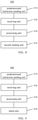
- FIG. 5 is a block diagram illustrating an apparatus for detecting a state of a proximity sensor according to some embodiments.
- the apparatus for detecting the state of the proximity sensor is applied to a terminal, and the terminal includes a proximity sensor and an antenna.
- an apparatus 800 for detecting the state of the proximity sensor includes a predetermined instruction sending unit 810 and a processing unit 830.
- the predetermined instruction sending unit 810 is configured to send a predetermined instruction to the proximity sensor.
- the processing unit 830 is configured to determine whether the proximity sensor is abnormal based on a feedback result of the proximity sensor to the predetermined instruction; and maintain the antenna transmitting power at a low power if the proximity sensor is abnormal.
- FIG. 6 is a block diagram illustrating an apparatus for detecting a state of a proximity sensor according to some embodiments, and referring to FIG. 6 , in some embodiments, the predetermined instruction includes a capacitance value detection instruction for enabling the proximity sensor to detect a background capacitance value of a background circuit, wherein the background circuit at least includes the proximity sensor; the apparatus 800 for detecting the state of the proximity sensor further includes: a receiving unit 820 configured to receive the background capacitance value sent by the proximity sensor in response to the capacitance value detection instruction; and a processing unit 830 further configured to determine that the proximity sensor is abnormal if an absolute value of difference between the background capacitance value and a standard value is greater than or equal to a deviation threshold.
- the processing unit 830 is further configured to: if the absolute value of the difference between the background capacitance value and the standard value is less than the deviation threshold, enable the antenna to adjust the transmitting power in real time based on a sensing signal of the proximity sensor.
- FIG. 7 is a block diagram illustrating an apparatus for detecting a state of a proximity sensor according to some embodiments, and referring to FIG. 7 , the apparatus 800 for detecting the state of the proximity sensor further includes a first sending unit 860, and the processing unit 830 sends a first instruction to the modem through the first sending unit 860, such that the modem receives the sensing signal of the proximity sensor, and the antenna transmitting power is controlled in real time based on the sensing signal.
- the processing unit 830 is further configured to determine that the proximity sensor is abnormal if a response of the proximity sensor is not received.
- the predetermined instruction includes a communication state detection instruction; and the predetermined instruction sending unit 810 is further configured to: send the communication state detection instruction to the proximity sensor periodically when the terminal is turned on and/or after the terminal is turned on.
- FIG. 8 is a block diagram illustrating an apparatus for detecting a state of a proximity sensor according to some embodiments, and referring to FIG. 8 , the apparatus 800 for detecting the state of the proximity sensor includes a second sending unit 840.
- the processing unit 830 sends a second instruction to the modem through the second sending unit 840, such that the modem controls the antenna transmitting power to maintain a low power, wherein the low power is an antenna transmitting power corresponding to the shortest distance between the human body and the terminal.
- FIG. 9 is a block diagram illustrating an apparatus for detecting a state of a proximity sensor according to some embodiments, and referring to FIG. 9 , the apparatus 800 for detecting the state of the proximity sensor includes an alarm unit 850.
- the alarm unit 850 is configured to send alarm information through the terminal when the proximity sensor is abnormal.
- the background circuit is a circuit on a circuit board
- the proximity sensor is mounted on the circuit board.
- FIG. 10 is a block diagram illustrating a device 600 for detecting a state of a proximity sensor according to some embodiments.
- the device 600 can be a phone, a computer, a digital broadcast terminal, a messaging device, a gaming console, a tablet, a medical device, exercise equipment, a personal digital assistant, and the like.
- the device 600 may include one or more of the following components: a processing component 602, a memory 604, a power component 606, a multimedia component 608, an audio component 610, an input/output (I/O) interface 612, a sensor component 614, and a communication component 616.
- the processing component 602 typically controls overall operations of the device 600, such as the operations associated with display, telephone calls, data communications, camera operations, and recording operations.
- the processing component 602 may include one or more processors 620 to execute instructions to implement all or part of the steps in the above described methods.
- the processing component 602 may include one or more modules which facilitate the interaction between the processing component 602 and other components.
- the processing component 602 may include a multimedia module to facilitate the interaction between the multimedia component 608 and the processing component 602.
- the memory 604 is configured to store various types of data to support the operation of the device 600. Examples of such data include instructions for any applications or methods operated on the device 600, contact data, phonebook data, messages, pictures, videos, etc.
- the memory 604 may be implemented by using any type of volatile or non-volatile memory devices, or a combination thereof, such as a static random access memory (SRAM), an electrically erasable programmable read-only memory (EEPROM), an erasable programmable read-only memory (EPROM), a programmable read-only memory (PROM), a read-only memory (ROM), a magnetic memory, a flash memory, a magnetic or optical disk.
- SRAM static random access memory
- EEPROM electrically erasable programmable read-only memory
- EPROM erasable programmable read-only memory
- PROM programmable read-only memory
- ROM read-only memory
- magnetic memory a magnetic memory
- flash memory a flash memory
- magnetic or optical disk a magnetic or
- the power component 606 supplies power to various components of the device 600.
- the power component 606 may include a power management system, one or more power sources, and other components associated with the generation, management, and distribution of power in the device 600.
- the multimedia component 608 includes a screen providing an output interface between the device 600 and a user.
- the screen may include a liquid crystal display (LCD) and a touch panel (TP).
- LCD liquid crystal display
- TP touch panel
- OLED organic light-emitting diode
- the screen can be implemented as a touch screen to receive input signals from the user.
- the touch panel includes one or more touch sensors to sense touches, swipes, and gestures on the touch panel.
- the touch sensors can not only sense a boundary of a touch or swipe action, but also sense a period of time and a pressure associated with the touch or swipe action.
- the multimedia component 608 includes a front camera and/or a rear camera.
- the front camera and/or the rear camera can receive external multimedia data while the device 600 is in an operation mode, such as a photographing mode or a video mode.
- Each of the front camera and the rear camera may be a fixed optical lens system or have focus and optical zoom capability.
- the audio component 610 is configured to output and/or input audio signals.
- the audio component 610 includes a microphone (MIC) configured to receive an external audio signal when the device 600 is in an operation mode, such as a call mode, a recording mode, and a voice recognition mode.
- the received audio signal can be further stored in the memory 604 or transmitted via the communication component 616.
- the audio component 610 further includes a speaker to output audio signals.
- the I/O interface 612 provides an interface between the processing component 602 and peripheral interface modules, such as a keyboard, a click wheel, buttons, and the like.
- the buttons may include, but are not limited to, a home button, a volume button, a starting button, and a locking button.
- the sensor component 614 includes one or more sensors to provide status assessments of various aspects of the device 600.
- the sensor component 614 can detect an on/off status of the device 600, relative positioning of components, e.g., the display and a keypad, of the device 600, the sensor component 614 can also detect a change in position of the device 600 or one component of the device 600, a presence or absence of user contact with the device 600, an orientation or an acceleration/deceleration of the device 600, and a change in temperature of the device 600.
- the sensor component 614 may include a proximity sensor configured to detect the presence of nearby objects without any physical contact.
- the sensor component 614 may also include a light sensor, such as a CMOS or CCD image sensor, for use in imaging applications.
- the sensor component 614 can also include an accelerometer sensor, a gyroscope sensor, a magnetic sensor, a pressure sensor, or a temperature sensor.
- the communication component 616 is configured to facilitate wired or wireless communication between the device 600 and other devices.
- the device 600 can access a wireless network based on a communication standard, such as Wi-Fi, 2G, 3G, 4G, or 5G, or a combination thereof.
- the communication component 616 receives a broadcast signal or broadcast associated information from an external broadcast management system via a broadcast channel.
- the communication component 616 further includes a near field communication (NFC) module to facilitate short-range communications.
- the NFC module can be implemented based on a radio frequency identification (RFID) technology, an infrared data association (IrDA) technology, an ultra-wideband (UWB) technology, a Bluetooth (BT) technology, and other technologies.
- RFID radio frequency identification
- IrDA infrared data association
- UWB ultra-wideband
- BT Bluetooth
- the device 600 may be implemented with one or more application specific integrated circuits (ASICs), digital signal processors (DSPs), digital signal processing devices (DSPDs), programmable logic devices (PLDs), field programmable gate arrays (FPGAs), controllers, micro-controllers, microprocessors, or other electronic components, for performing the above described methods.
- ASICs application specific integrated circuits
- DSPs digital signal processors
- DSPDs digital signal processing devices
- PLDs programmable logic devices
- FPGAs field programmable gate arrays
- controllers micro-controllers, microprocessors, or other electronic components, for performing the above described methods.
- non-transitory computer-readable storage medium including instructions, such as the memory 604 including the instructions executable by the processor 620 in the device 600, for completing the above described methods for detecting the state of the proximity sensor.
- the non-transitory computer-readable storage medium can be a ROM, a random access memory (RAM), a CD-ROM, a magnetic tape, a floppy disc, an optical data storage device, and the like.
- Various embodiments of the present disclosure can have the following advantages: through the feedback of the proximity sensor to the request to obtain the capacitance value, it is determined whether the proximity sensor can work normally, and in a case that the proximity sensor cannot work normally, the antenna transmitting power is directly reduced and maintained at a low power level, thereby avoiding the situation that the antenna transmitting power is still higher when the human body is approaching due to the inability of the proximity sensor to work normally, which reduces the radiation hazard to the human body.
- the "plurality” in the disclosure means two or more, and other quantifiers are similar.
- “And/or” describes the relationship of the related objects, indicating that there may be three relationships, for example, A and/or B may indicate three cases: A exists alone, A and B exist simultaneously, and B exists alone.
- the character “/” generally indicates that the relationship between the contextually relevant objects is a “or” relationship.
- the singular forms “a,” “an,” and “the” are also intended to include the plural forms unless the context clearly indicates otherwise.
- first and second are used to describe various information, these information should not be limited by these terms. The terms are only used to distinguish the same type of information from each other, and do not indicate a specific order or importance. In fact, the expressions such as “first” and “second” can be used interchangeably. For instance, first information can also be referred to as second information without departing from the scope of the disclosure, and similarly, the second information can also be referred to as the first information.
- connection includes a direct connection between the two without other components, and also includes an indirect connection between the two with other elements.
Abstract
Description
- With the rapid development of technologies, users increasingly rely on mobile terminals in all aspects of their work and life. While using a mobile terminal, as the distance between the user and the mobile terminal is relatively close, the radiation from the mobile device is unavoidable.
- The present disclosure generally relates to the field of terminal technology, and more specifically, to a method for detecting a state of a proximity sensor, an apparatus for detecting the state of the proximity sensor, a terminal and a non-transitory computer-readable storage medium.
- According to one aspect of embodiments of the present disclosure, there is provided a method for detecting a state of a proximity sensor, applied to a terminal comprising the proximity sensor and an antenna, the method comprising: sending a predetermined instruction to the proximity sensor; determining whether the proximity sensor is abnormal based on a feedback result of the proximity sensor to the predetermined instruction; and maintaining the antenna transmitting power at a low power when the proximity sensor is abnormal.
- In some embodiments, the predetermined instruction comprises a capacitance value detection instruction for enabling the proximity sensor to detect a background capacitance value of a background circuit, wherein the background circuit at least includes the proximity sensor; and the determining whether the proximity sensor is abnormal based on the feedback result of the proximity sensor to the predetermined instruction comprises: when the background capacitance value sent by the proximity sensor in response to the capacitance value detection instruction is received, determining whether an absolute value of difference between the background capacitance value and a standard value is greater than or equal to a deviation threshold; and when the absolute value of the difference between the background capacitance value and the standard value is greater than or equal to the deviation threshold, determining that the proximity sensor is abnormal.
- In some embodiments, the determining whether the proximity sensor is abnormal based on the feedback result of the proximity sensor to the predetermined instruction comprises: when the absolute value of the difference between the background capacitance value and the standard value is less than the deviation threshold, enabling the antenna to adjust the transmitting power in real time based on a sensing signal of the proximity sensor.
- In some embodiments, the enabling the antenna to adjust the transmitting power in real time based on the signal of the proximity sensor comprises: sending a first instruction to a modem, such that the modem receives the sensing signal of the proximity sensor, and controls the antenna transmitting power in real time based on the sensing signal.
- In some embodiments, the determining whether the proximity sensor is abnormal based on the feedback result of the proximity sensor comprises: when a response of the proximity sensor is not received, determining that the proximity sensor is abnormal.
- In some embodiments, the predetermined instruction comprises a communication state detection instruction; and the sending the predetermined instruction to the proximity sensor comprises: sending the communication state detection instruction to the proximity sensor periodically when the terminal is turned on and/or after the terminal is turned on.
- In some embodiments, the maintaining the antenna transmitting power at the low power comprises: sending a second instruction to the modem, such that the modem controls the antenna transmitting power to maintain a low power, wherein the low power is an antenna transmitting power corresponding to the shortest distance between a human body and the terminal.
- In some embodiments, in a case in which the proximity sensor is abnormal, the method further comprises: sending alarm information through the terminal.
- In some embodiments, the background circuit is a circuit on a circuit board on which the proximity sensor is mounted.
- According to a second aspect of embodiments of the present disclosure, there is provided an apparatus for detecting a state of a proximity sensor, applied to a terminal comprising the proximity sensor and an antenna, the apparatus comprising: a predetermined instruction sending unit, configured to send a predetermined instruction to the proximity sensor; and a processing unit, configured to determine whether the proximity sensor is abnormal based on a feedback result of the proximity sensor to the predetermined instruction; and maintain the antenna transmitting power at a low power when the proximity sensor is abnormal.
- In some embodiments, the predetermined instruction comprises a capacitance value detection instruction for enabling the proximity sensor to detect a background capacitance value of a background circuit, wherein the background circuit at least includes the proximity sensor; the apparatus for detecting the state of the proximity sensor further comprises: a receiving unit configured to receive the background capacitance value sent by the proximity sensor in response to the capacitance value detection instruction; and the processing unit is further configured to determine that the proximity sensor is abnormal when an absolute value of difference between the background capacitance value and the standard value is greater than or equal to a deviation threshold.
- In some embodiments, the processing unit is further configured to: when the absolute value of the difference between the background capacitance value and the standard value is less than the deviation threshold, enable the antenna to adjust the transmitting power in real time based on a sensing signal of the proximity sensor.
- In some embodiments, the apparatus further comprises a first sending unit, and the processing unit sends a first instruction to a modem through the first sending unit, such that the modem receives the sensing signal of the proximity sensor, and controls the antenna transmitting power in real time based on the sensing signal.
- In some embodiments, the processing unit is further configured to: when a response of the proximity sensor is not received, determine that the proximity sensor is abnormal.
- In some embodiments, the predetermined instruction comprises a communication state detection instruction; and the predetermined instruction sending unit is further configured to: send the communication state detection instruction to the proximity sensor periodically when the terminal is turned on and/or after the terminal is turned on.
- In some embodiments, the apparatus further comprises a second sending unit, and the processing unit sends a second instruction to the modem through the second sending unit, such that the modem controls the antenna transmitting power to maintain a low power, wherein the low power is an antenna transmitting power corresponding to the shortest distance between a human body and the terminal.
- In some embodiments, the apparatus further comprises: an alarm unit, configured to send alarm information through the terminal when the proximity sensor is abnormal.
- In some embodiments, the background circuit is a circuit on a circuit board on which the proximity sensor is mounted.
- According to a third aspect of embodiments of the present disclosure, there is provided a terminal comprising: a processor; and memory for storing processor-executable instructions, wherein the processor is configured to execute the method for detecting the state of the proximity sensor according to the foregoing first aspect.
- According to another aspect of embodiments of the present disclosure, there is provided a non-transitory computer-readable storage medium having instructions stored thereon, wherein the method for detecting the state of the proximity sensor according to the first aspect is executed, when the instructions are executed by a processor.
- It is to be understood that both the foregoing general description and the following detailed description are exemplary and explanatory only and are not restrictive of the disclosure.
- The accompanying drawings, which are incorporated in and constitute a part of this specification, illustrate embodiments consistent with the present disclosure and, together with the description, serve to explain the principles of the present disclosure.
-
FIG. 1 is a flowchart illustrating a method for detecting a state of a proximity sensor according to some embodiments of the present disclosure. -
FIG. 2 is a flowchart illustrating a method for detecting a state of a proximity sensor according to some embodiments of the present disclosure. -
FIG. 3 is a flowchart illustrating a method for detecting a state of a proximity sensor according to some embodiments of the present disclosure. -
FIG. 4 is a flowchart illustrating a method for detecting a state of a proximity sensor according to some embodiments of the present disclosure. -
FIG. 5 is a block diagram illustrating an apparatus for detecting a state of a proximity sensor according to some embodiments of the present disclosure. -
FIG. 6 is a block diagram illustrating an apparatus for detecting a state of a proximity sensor according to some embodiments of the present disclosure. -
FIG. 7 is a block diagram illustrating an apparatus for detecting a state of a proximity sensor according to some embodiments of the present disclosure. -
FIG. 8 is a block diagram illustrating an apparatus for detecting a state of a proximity sensor according to some embodiments of the present disclosure. -
FIG. 9 is a block diagram illustrating an apparatus for detecting a state of a proximity sensor according to some embodiments of the present disclosure. -
FIG. 10 is a block diagram illustrating a device according to some embodiments of the present disclosure. - Description will now be made in detail to exemplary embodiments, examples of which are illustrated in the accompanying drawings. The following description refers to the accompanying drawings in which the same numbers in different drawings represent the same or similar elements unless otherwise represented. The implementations set forth in the following description of exemplary embodiments do not represent all implementations consistent with the present disclosure. Instead, they are merely examples of apparatuses and methods consistent with aspects related to the present disclosure as recited in the appended claims.
- The radiation from the mobile terminal may be harmful to the health of the user. The radiation level of the terminal can be measured by an electromagnetic wave absorption ratio, and in order to monitor the radiation of the mobile terminal, a proximity sensor such as an electromagnetic wave specific absorption ratio sensor (SAR Sensor) can be mounted in the terminal. The electromagnetic wave specific absorption ratio sensor can effectively detect the contact between the human body and the mobile terminal when the distance therebetween is close, report data every time a person approaches, and reduce the transmitting power according to the reported content to reduce the possible adverse effects of the terminal radiation on the human body.
- However, when the electromagnetic wave specific absorption ratio sensor cannot effectively monitor the radiation level generated by the terminal, once the radiation level exceeds the normal radiation value, it will bring varying degrees of harm to the human body and endanger the safety of users.
- The terminal antenna performance has an important index, that is, an electromagnetic wave absorption ratio SAR for representing the electromagnetic radiation energy absorbed by a unit mass of material per unit time. Under the action of an external electromagnetic field, an induced electromagnetic field will be generated in the human body. Since various organs of the human body are lossy media, the electromagnetic field in the body will generate electric current, which leads to the absorption and dissipation of electromagnetic energy. The meaning of SAR is the electromagnetic power absorbed or consumed per unit mass of human tissue. In the international market, in order to ensure the safety of end users, for example, the European Council and the Federal Communications Commission have high requirements for SAR.
- The radiation level of the terminal is measured by SAR, and in order to monitor the radiation of the mobile terminal, a proximity sensor such as a SAR sensor can be mounted in the terminal. The SAR sensor can effectively detect the contact between the human body and the mobile terminal when the distance therebetween is close, report data every time a person approaches, and reduce the transmitting power according to the reported content to reduce the possible adverse effects of terminal radiation on the human body.
- However, when the electromagnetic wave specific absorption ratio sensor cannot effectively monitor the level of the radiation generated by the terminal, once the radiation level exceeds the normal radiation value, it will bring varying degrees of harm to the human health and endanger the safety of users.
- With respect to the above described problems, the present disclosure provides a method for detecting a state of a proximity sensor, an apparatus for detecting the state of the proximity sensor, a terminal and a non-transitory computer-readable storage medium.
-
FIG. 1 is a flowchart illustrating a method for detecting a state of a proximity sensor according to some embodiments, and as shown inFIG. 1 , the method for detecting the state of the proximity sensor is used in a terminal. The terminal can be, for example, a smart phone, a tablet computer, a wearable device, a PC, or the like, and the embodiments of the present disclosure do not limit the types of devices to be applied. For ease of description, in the following description of the present disclosure, the terminal is a smart phone as an example for description. The terminal applying the present disclosure is provided with a proximity sensor and an antenna, and as shown inFIG. 1 , the method for detecting the state of the proximity sensor includes step S101,step S 102, and step S 103. - In step S101, a predetermined instruction is sent to the proximity sensor.
- The proximity sensor is a sensor that can sense the proximity of an object without contact and convert it into an electrical signal. For a terminal provided with a proximity sensor, it can be configured to perform proximity detection through the proximity sensor, so as to detect whether there is an object approaching a certain position of the smart terminal, and trigger the corresponding function. For example, while using a smart phone to make and receive a phone call, the proximity sensor can be used to detect whether there is an object approaching the handset of the phone. When it is determined that the user's head and face are close to the phone, the smart phone can be triggered to turn off the screen, etc.
- In the embodiments of the present disclosure, the proximity sensor is a SAR sensor, and the SAR sensor is used to detect the contact between the human body and the phone when the distance therebetween is close and report data every time a person approaches.
- In step S102, it is determined whether the proximity sensor is abnormal based on a feedback result of the proximity sensor to the predetermined instruction.
- After sending the predetermined instruction to the SAR sensor, it is determined whether the SAR sensor is abnormal according to the actual different feedback results.
- In some embodiments, as shown in
FIG. 2 , the predetermined instruction includes a capacitance value detection instruction, the host sends the capacitance value detection instruction for enabling the SAR sensor to detect a background capacitance value of a background circuit to the SAR sensor. The SAR sensor detects the background capacitance value of the background circuit in response to the received capacitance value detection instruction. The background circuit can be adjacent to or enclose the SAR sensor, e.g., a circuit surrounding the SAR sensor and having the SAR sensor therein. For example, the SAR sensor is mounted on a circuit board, the background circuit can be the circuit on the circuit board, and the background capacitance value can be the capacitance value of the circuit board. - The step S102 can include step S1021 and step S1022, in step S1021, if the background capacitance value sent by the proximity sensor in response to the capacitance value detection instruction is received, it is determined whether an absolute value of difference between the background capacitance value and a standard value is greater than or equal to a deviation threshold; and in step S1022, if the absolute value of the difference between the background capacitance value and the standard value is greater than or equal to the deviation threshold, it is determined that the proximity sensor is abnormal.
- In response to the received capacitance value detection instruction, the SAR sensor can be triggered to perform a self-calibration, that is, to detect the background capacitance value of the background circuit. And the detected background capacitance value is sent to the host.
- The background capacitance value of the background circuit is the capacitance value of the background circuit including the SAR sensor. It can be understood that the standard value compared with the background capacitance value is the capacitance value of the SAR sensor when data of the SAR sensor antenna of the phone is calibrated when the phone is shipped from the factory, that is, when there is no human contact. Different terminals have different standard values and background capacitance values according to their different configurations.
- In the embodiments of the present disclosure, due to the working characteristic of the SAR sensor and the damage of the phone components in use, the capacitor of the background circuit including the SAR sensor or other components may be depreciated and invalid. At this time, the SAR sensor cannot work normally. The deviation threshold is set in advance, and in the determination process, it is determined whether the absolute value of the difference between the background capacitance value and the standard value is greater than or equal to the deviation threshold.
- When the absolute value of the difference between the background capacitance value and the standard value is greater than or equal to the deviation threshold, it is determined that the SAR sensor cannot work normally.
- When the absolute value of the difference between the background capacitance value and the standard value is less than the deviation threshold, it is determined that the SAR sensor can work normally.
- When determining that the SAR sensor cannot work normally, it is determined that there is an abnormality, and a SAR value for representing the radiation produced by the phone cannot be obtained. When the human body is close to the phone, since the radiation situation cannot be determined, the antenna transmitting power of the phone is not reduced, such that the phone still maintains a higher power to work, and thus greater electromagnetic wave radiation is generated to the user, which brings harm to the user's body.
- In step S103, if the proximity sensor is abnormal, the antenna transmitting power is maintained at a low power.
- In the embodiments of the present disclosure, the low power can be the lowest antenna transmitting power of the phone, that is, can be the corresponding antenna transmitting power when the shortest distance between the human body and the terminal is detected in a case that the SAR sensor works normally. By maintaining the antenna transmitting power of the phone at the lowest transmitting power, the radiation of the phone is reduced, which not only ensures the normal use of the phone, but also ensures the safety of the user.
- According to the embodiments of the present disclosure, it is determined whether the proximity sensor can work normally through the acquisition of the capacitance value by the proximity sensor, and when it is determined that the proximity sensor cannot work normally, the antenna transmitting power is directly reduced and maintained at a low power level, thereby avoiding the situation that the antenna transmitting power is still high when the human body approaches due to the inability of the proximity sensor to work normally, and reducing the radiation hazard to the human body.
-
FIG. 3 is a flowchart illustrating a method for detecting a state of a proximity sensor according to some embodiments of the present disclosure. As shown inFIG. 3 , the method for detecting the state of the proximity sensor includes the following steps. - In step S201, a predetermined instruction is sent to the proximity sensor.
- In step S202, when no response from the proximity sensor is received, it is determined that the proximity sensor is abnormal.
- In step S203, when the proximity sensor is abnormal, the antenna transmitting power is maintained at a low power.
- After sending the predetermined instruction to the proximity sensor, if no response from the SAR sensor is received, there may be abnormal communication with the SAR sensor, and when the communication between the host and the SAR sensor chip fails, the data of the SAR sensor for determining the distance between the human body and the terminal cannot be obtained, and thus the antenna transmitting power cannot be adjusted specifically according to the distance from the human body. Therefore, it can also be determined that the SAR sensor cannot work normally, that is, there is an abnormality.
- When it is determined that the SAR sensor cannot work normally, the SAR value for representing the radiation generated by the phone cannot be obtained. When the human body is close to the phone, since the radiation situation cannot be determined, the antenna transmitting power of the phone is not reduced, such that the phone still maintains a high power to work, and thus greater electromagnetic wave radiation is generated to the user, which brings harm to the user's body.
- In order to reduce the user's physical damage that may be caused by excessive radiation, the antenna transmitting power is maintained at a low power, that is, the phone is maintained at the lowest antenna transmitting power to work. By maintaining the antenna transmitting power of the phone at the lowest transmitting power to reduce the radiation of the phone, not only the normal use of the phone but also the safety of the user is ensured.
- In some embodiments, the predetermined instruction includes a communication state detection instruction; and the sending the predetermined instruction to the proximity sensor includes sending a communication state detection instruction to the proximity sensor periodically when the terminal is turned on and/or after the terminal is turned on.
- In the embodiment, the communication state detection instruction can be sent to the SAR sensor to detect whether the communication state with the SAR sensor is normal. The sending can be performed when the terminal is turned on to detect the communication state, or the detection can be periodically made after the terminal is turned on, that is, one communication state detection instruction is sent at a certain interval, and the feedback of the communication state detection instruction can be made through the SAR sensor to determine whether there is a communication abnormality, and in general, it can be determined that the communication is normal by enabling the SAR sensor return a feedback signal to confirm the reception after receiving the communication state detection instruction, and if the feedback signal is not received, it means that there is a communication abnormality. Herein, the communication state detection instruction can be sent to the SAR sensor through any one of the communication methods such as I2C (Inter-Integrated Circuit, two-wire serial bus), I2S (Inter-Integrated Circuit Sound, integrated circuit built-in audio bus), USB (Universal Serial Bus), and PCI (Peripheral Component Interconnect, peripheral component interconnect standard).
- According to the embodiments of the present disclosure, the communication state of the SAR sensor is determined in the above described manner to avoid the inability to obtain the detection data of the SAR sensor due to the abnormal communication state and the inability to reduce the antenna power when the human body approaches. Therefore, the situation that the antenna transmitting power is still high when the human body approaches due to the inability of the SAR sensor to work normally is avoided, and the radiation hazard to the human body is reduced.
- In some embodiments, a second instruction is sent to the modem, such that the modem controls the antenna transmitting power to maintain a low power, wherein the low power is an antenna transmitting power corresponding to the shortest distance between the human body and the terminal.
- In the embodiments of the present disclosure, when the absolute value of the difference between the background capacitance value and the standard value is greater than or equal to the deviation threshold, or the communication between the host and the SAR sensor chip fails, it is determined that the SAR sensor cannot work normally.
- When it is determined that the SAR sensor cannot work normally, the host sends a second instruction to the modem, and the second instruction is used to notify the modem to control the antenna transmitting power to maintain a low power, that is, to maintain the phone to work at the lowest antenna transmitting power. It avoids the situation that the antenna transmitting power is still higher when the human body approaches due to the inability of the proximity sensor to work normally, and reduces the radiation hazard to the human body.
- In some embodiments, when the proximity sensor is abnormal, the method for detecting the state of the proximity sensor can further include: sending alarm information through the terminal.
- In the embodiments of the present disclosure, when the absolute value of the difference between the background capacitance value and the standard value is greater than or equal to the deviation threshold, or the communication between the host and the SAR sensor chip fails, it is determined that the SAR sensor cannot work normally.
- When it is determined that the SAR sensor cannot work normally, the alarm information is sent through the terminal.
- For example, the sending the alarm information through the terminal can be that prompt information is displayed on the terminal display screen to remind the user that the SAR sensor cannot work normally and the terminal being used may have excessive radiation, and the antenna transmitting power is reduced for the user to choose and deal with.
- The user can determine whether to accept the operation of reducing the phone transmitting power of the antenna according to actual usage requirements. It can be understood that the operation of reducing the phone transmitting power of the antenna may reduce the signal quality during the use of the phone and affect the user experience. When a user needs to use the phone for important, high-level operation, it can be selected not to accept the operation of reducing the antenna transmitting power of the phone according to the prompts to keep the phone with good signal quality to be used.
- When the user uses the phone to perform the general operation, it can be selected to accept the operation of reducing the antenna transmitting power of the phone according to the prompts to reduce the radiation of the phone to the human body and ensure safety. Alternatively, the use time of phone can be reasonably reduced and SAR sensor failures can be dealt with in time.
- The sending the alarm information through the terminal can also be sending a sound reminder at the terminal, for example, sending an alarm sound, a prompt sound, etc., to remind the user that the SAR sensor cannot work normally and there may be excessive radiation if the terminal is used, for the user to choose and deal with.
- The sending the alarm information through the terminal can also be sending error-reporting information to the cloud server. The cloud server can obtain the fault information of the SAR sensor in the phone, which is convenient for information collection and product fault processing, so as to improve the quality of the phone and provide better service to users.
- According to the embodiments of the present disclosure, the alarm information is sent through the terminal to further provide the user with active choice, which avoids the situation that the antenna transmitting power is still high when the human body approaches due to the inability of the proximity sensor to work normally, reduces the radiation hazard to the human body, and ensures the normal use of the terminal in critical situations.
-
FIG. 4 is a flowchart illustrating a method for detecting a state of a proximity sensor according to some embodiments of the present disclosure. As shown inFIG. 4 , the method for detecting the state of the proximity sensor includes the following steps. - In step S301, a predetermined instruction is sent to the proximity sensor, wherein the predetermined instruction includes a capacitance value detection instruction for enabling the proximity sensor to detect a background capacitance value of a background circuit, and the background circuit at least includes the proximity sensor.
- In step S302, when the background capacitance value sent by the proximity sensor in response to the capacitance value detection instruction is received, it is determined whether the absolute value of the difference between the background capacitance value and the standard value is greater than or equal to the deviation threshold.
- In step S303, when the absolute value of the difference between the background capacitance value and the standard value is greater than or equal to the deviation threshold, it is determined that the proximity sensor is abnormal.
- In step S304, when the proximity sensor is abnormal, the antenna transmitting power is maintained at a low power.
- In step S305, when the absolute value of the difference between the background capacitance value and the standard value is less than the deviation threshold, the antenna is enabled to adjust the transmitting power in real time based on a sensing signal of the proximity sensor.
- In the embodiments of the present disclosure, when the absolute value of the difference between the background capacitance value and the standard value is greater than or equal to the deviation threshold, or the communication between the host and the SAR sensor chip fails, it is determined that the SAR sensor cannot work normally.
- When it is determined that the SAR sensor cannot work normally, the host sends a second instruction to the modem, and the second instruction is used to notify the modem to control the antenna transmitting power to maintain a low power, that is, to maintain the phone to work at the lowest antenna transmitting power.
- The host sends the capacitance value detection instruction to the SAR sensor, and the capacitance value detection instruction is used to enable the SAR sensor to detect the background capacitance value of the background circuit. The SAR sensor detects the background capacitance value of the background circuit in response to the received capacitance value detection instruction.
- The SAR sensor detects the background capacitance value of the background circuit in response to the received capacitance value detection instruction, and sends the detected background capacitance value to the host.
- When the absolute value of the difference between the background capacitance value and the standard value is less than the deviation threshold, it is determined that the SAR sensor can work normally.
- When it is determined that the SAR sensor can work normally after re-detecting, in order to bring good communication signal quality to the user, the antenna transmitting power of the phone is restored to the normal working level, such that the antenna can adjust the transmitting power in real time based on the sensing signal of the proximity sensor.
- According to the embodiments of the present disclosure, when it is determined that the SAR sensor cannot work normally, the antenna transmitting power is controlled to be maintained at a low power, that is, the phone is maintained to work at the lowest antenna transmitting power. When it is determined that the SAR sensor can work normally after re-detecting, the antenna is enabled to adjust the transmitting power in real time based on the sensing signal of the proximity sensor. It prevents the user from being exposed to high radiation, in this way, not only is the safety of users ensured, but also the transmitting power can be adjusted in time according to the sensing signal of the SAR sensor, thereby ensuring the communication quality of the phone and improving the user experience.
- In some embodiments, in step S305, when the absolute value of the difference between the background capacitance value and the standard value is less than the deviation threshold, the first instruction can be sent to the modem to enable the modem to receive the sensing signal of the proximity sensor.
- In the embodiments of the present disclosure, when the absolute value of the difference between the background capacitance value and the standard value is greater than or equal to the deviation threshold, or the communication between the host and the SAR sensor chip fails, it is determined that the SAR sensor cannot work normally.
- When it is determined that the SAR sensor cannot work normally, the host sends a second instruction to the modem, and the second instruction is used to notify the modem to control the antenna transmitting power to maintain a low power, that is, to maintain the phone to work at the lowest antenna transmitting power.
- When it is determined that the SAR sensor can work normally after re-detecting, in order to bring good communication signal quality to the user, the antenna transmitting power of the phone is restored to the normal working level, that is, the antenna is enabled to adjust the transmitting power based on the sensing signal of the SAR sensor.
- The antenna transmitting power is controlled in real time based on the comparison between the sensing signal of the SAR sensor and the standard value. For example, the linear adjustment can be performed according to the absolute value of the difference between the sensing signal and the standard value, and the proportional relationship with the standard value, or other adjustment methods.
- According to the embodiments of the present disclosure, by controlling the modem to receive the sensing signal of the SAR sensor, the antenna transmitting power is controlled in real time based on the sensing signal, the influence of phone radiation on the human body and the strength of the phone signal are considered in aggregate, the antenna transmitting power of the phone is adjusted in time, such that the adjustment of the transmitting power is more effective, and the user's normal phone experience is ensured.
- In some embodiments, the background circuit is a circuit on a circuit board, and the proximity sensor is mounted on the circuit board.
- In the embodiments of the present disclosure, the capacitance detected by the SAR sensor is the capacitance of the circuit board where the SAR sensor is mounted, that is, the capacitance detected by the SAR sensor includes the capacitance of other components on the circuit board and the SAR sensor itself.
- The background circuit including the SAR sensor is a circuit surrounding the SAR sensor and including the SAR sensor. The circuit is mounted on a circuit board, which can be a rigid circuit board or a flexible circuit board. The rigid circuit board can be, for example, a rigid printed circuit board, which has low cost, simpler structure and easy assembly.
- The flexible circuit board can be bent, twisted or folded arbitrarily, with characteristics of flexible assembly and low requirements for assembly space, and widely used.
- Based on the same concept, the embodiments of the present disclosure also provide an apparatus for detecting the state of the proximity sensor.
- It can be understood that, in order to implement the above functions, the apparatus for detecting the state of the proximity sensor provided by the embodiments of the present disclosure includes a corresponding hardware structure and/or software module for executing each function. In combination with the units and algorithm steps of the respective examples disclosed in the embodiments of the present disclosure, the embodiments of the present disclosure can be implemented in the form of hardware or a combination of hardware and computer software. Whether a function is executed by the hardware or a method of driving the hardware by the computer software depends on the specific application and design constraints of the technical solution. A person skilled in the art may use different methods to implement the described functions for each specific application, but such implementation should not be considered to exceed the scope of the technical solutions of the embodiments of the present disclosure.
-
FIG. 5 is a block diagram illustrating an apparatus for detecting a state of a proximity sensor according to some embodiments. The apparatus for detecting the state of the proximity sensor is applied to a terminal, and the terminal includes a proximity sensor and an antenna. Referring toFIG. 5 , anapparatus 800 for detecting the state of the proximity sensor includes a predeterminedinstruction sending unit 810 and aprocessing unit 830. - The predetermined
instruction sending unit 810 is configured to send a predetermined instruction to the proximity sensor. - The
processing unit 830 is configured to determine whether the proximity sensor is abnormal based on a feedback result of the proximity sensor to the predetermined instruction; and maintain the antenna transmitting power at a low power if the proximity sensor is abnormal. -
FIG. 6 is a block diagram illustrating an apparatus for detecting a state of a proximity sensor according to some embodiments, and referring toFIG. 6 , in some embodiments, the predetermined instruction includes a capacitance value detection instruction for enabling the proximity sensor to detect a background capacitance value of a background circuit, wherein the background circuit at least includes the proximity sensor; theapparatus 800 for detecting the state of the proximity sensor further includes: a receivingunit 820 configured to receive the background capacitance value sent by the proximity sensor in response to the capacitance value detection instruction; and aprocessing unit 830 further configured to determine that the proximity sensor is abnormal if an absolute value of difference between the background capacitance value and a standard value is greater than or equal to a deviation threshold. - In some embodiments, the
processing unit 830 is further configured to: if the absolute value of the difference between the background capacitance value and the standard value is less than the deviation threshold, enable the antenna to adjust the transmitting power in real time based on a sensing signal of the proximity sensor. -
FIG. 7 is a block diagram illustrating an apparatus for detecting a state of a proximity sensor according to some embodiments, and referring toFIG. 7 , theapparatus 800 for detecting the state of the proximity sensor further includes afirst sending unit 860, and theprocessing unit 830 sends a first instruction to the modem through the first sendingunit 860, such that the modem receives the sensing signal of the proximity sensor, and the antenna transmitting power is controlled in real time based on the sensing signal. - In some embodiments, the
processing unit 830 is further configured to determine that the proximity sensor is abnormal if a response of the proximity sensor is not received. - In some embodiments, the predetermined instruction includes a communication state detection instruction; and the predetermined
instruction sending unit 810 is further configured to: send the communication state detection instruction to the proximity sensor periodically when the terminal is turned on and/or after the terminal is turned on. -
FIG. 8 is a block diagram illustrating an apparatus for detecting a state of a proximity sensor according to some embodiments, and referring toFIG. 8 , theapparatus 800 for detecting the state of the proximity sensor includes asecond sending unit 840. - The
processing unit 830 sends a second instruction to the modem through thesecond sending unit 840, such that the modem controls the antenna transmitting power to maintain a low power, wherein the low power is an antenna transmitting power corresponding to the shortest distance between the human body and the terminal. -
FIG. 9 is a block diagram illustrating an apparatus for detecting a state of a proximity sensor according to some embodiments, and referring toFIG. 9 , theapparatus 800 for detecting the state of the proximity sensor includes analarm unit 850. - The
alarm unit 850 is configured to send alarm information through the terminal when the proximity sensor is abnormal. - In some embodiments, the background circuit is a circuit on a circuit board, and the proximity sensor is mounted on the circuit board.
- With respect to the apparatuses in the above embodiments, the specific manners for performing operations for individual modules therein have been described in detail in the embodiments regarding the methods, which will not be elaborated herein.
-
FIG. 10 is a block diagram illustrating adevice 600 for detecting a state of a proximity sensor according to some embodiments. For example, thedevice 600 can be a phone, a computer, a digital broadcast terminal, a messaging device, a gaming console, a tablet, a medical device, exercise equipment, a personal digital assistant, and the like. - Referring to
FIG. 10 , thedevice 600 may include one or more of the following components: aprocessing component 602, amemory 604, apower component 606, amultimedia component 608, anaudio component 610, an input/output (I/O)interface 612, asensor component 614, and acommunication component 616. - The
processing component 602 typically controls overall operations of thedevice 600, such as the operations associated with display, telephone calls, data communications, camera operations, and recording operations. Theprocessing component 602 may include one ormore processors 620 to execute instructions to implement all or part of the steps in the above described methods. Moreover, theprocessing component 602 may include one or more modules which facilitate the interaction between theprocessing component 602 and other components. For instance, theprocessing component 602 may include a multimedia module to facilitate the interaction between themultimedia component 608 and theprocessing component 602. - The
memory 604 is configured to store various types of data to support the operation of thedevice 600. Examples of such data include instructions for any applications or methods operated on thedevice 600, contact data, phonebook data, messages, pictures, videos, etc. Thememory 604 may be implemented by using any type of volatile or non-volatile memory devices, or a combination thereof, such as a static random access memory (SRAM), an electrically erasable programmable read-only memory (EEPROM), an erasable programmable read-only memory (EPROM), a programmable read-only memory (PROM), a read-only memory (ROM), a magnetic memory, a flash memory, a magnetic or optical disk. - The
power component 606 supplies power to various components of thedevice 600. Thepower component 606 may include a power management system, one or more power sources, and other components associated with the generation, management, and distribution of power in thedevice 600. - The
multimedia component 608 includes a screen providing an output interface between thedevice 600 and a user. In some embodiments, the screen may include a liquid crystal display (LCD) and a touch panel (TP). In some embodiments, an organic light-emitting diode (OLED) display can be employed. - If the screen includes the touch panel, the screen can be implemented as a touch screen to receive input signals from the user. The touch panel includes one or more touch sensors to sense touches, swipes, and gestures on the touch panel. The touch sensors can not only sense a boundary of a touch or swipe action, but also sense a period of time and a pressure associated with the touch or swipe action. In some embodiments, the
multimedia component 608 includes a front camera and/or a rear camera. The front camera and/or the rear camera can receive external multimedia data while thedevice 600 is in an operation mode, such as a photographing mode or a video mode. Each of the front camera and the rear camera may be a fixed optical lens system or have focus and optical zoom capability. - The
audio component 610 is configured to output and/or input audio signals. For example, theaudio component 610 includes a microphone (MIC) configured to receive an external audio signal when thedevice 600 is in an operation mode, such as a call mode, a recording mode, and a voice recognition mode. The received audio signal can be further stored in thememory 604 or transmitted via thecommunication component 616. In some embodiments, theaudio component 610 further includes a speaker to output audio signals. - The I/
O interface 612 provides an interface between theprocessing component 602 and peripheral interface modules, such as a keyboard, a click wheel, buttons, and the like. The buttons may include, but are not limited to, a home button, a volume button, a starting button, and a locking button. - The
sensor component 614 includes one or more sensors to provide status assessments of various aspects of thedevice 600. For instance, thesensor component 614 can detect an on/off status of thedevice 600, relative positioning of components, e.g., the display and a keypad, of thedevice 600, thesensor component 614 can also detect a change in position of thedevice 600 or one component of thedevice 600, a presence or absence of user contact with thedevice 600, an orientation or an acceleration/deceleration of thedevice 600, and a change in temperature of thedevice 600. Thesensor component 614 may include a proximity sensor configured to detect the presence of nearby objects without any physical contact. Thesensor component 614 may also include a light sensor, such as a CMOS or CCD image sensor, for use in imaging applications. In some embodiments, thesensor component 614 can also include an accelerometer sensor, a gyroscope sensor, a magnetic sensor, a pressure sensor, or a temperature sensor. - The
communication component 616 is configured to facilitate wired or wireless communication between thedevice 600 and other devices. Thedevice 600 can access a wireless network based on a communication standard, such as Wi-Fi, 2G, 3G, 4G, or 5G, or a combination thereof. In one exemplary embodiment, thecommunication component 616 receives a broadcast signal or broadcast associated information from an external broadcast management system via a broadcast channel. In one exemplary embodiment, thecommunication component 616 further includes a near field communication (NFC) module to facilitate short-range communications. For example, the NFC module can be implemented based on a radio frequency identification (RFID) technology, an infrared data association (IrDA) technology, an ultra-wideband (UWB) technology, a Bluetooth (BT) technology, and other technologies. - In exemplary embodiments, the
device 600 may be implemented with one or more application specific integrated circuits (ASICs), digital signal processors (DSPs), digital signal processing devices (DSPDs), programmable logic devices (PLDs), field programmable gate arrays (FPGAs), controllers, micro-controllers, microprocessors, or other electronic components, for performing the above described methods. - In exemplary embodiments, there is also provided a non-transitory computer-readable storage medium including instructions, such as the
memory 604 including the instructions executable by theprocessor 620 in thedevice 600, for completing the above described methods for detecting the state of the proximity sensor. For example, the non-transitory computer-readable storage medium can be a ROM, a random access memory (RAM), a CD-ROM, a magnetic tape, a floppy disc, an optical data storage device, and the like. - Various embodiments of the present disclosure can have the following advantages: through the feedback of the proximity sensor to the request to obtain the capacitance value, it is determined whether the proximity sensor can work normally, and in a case that the proximity sensor cannot work normally, the antenna transmitting power is directly reduced and maintained at a low power level, thereby avoiding the situation that the antenna transmitting power is still higher when the human body is approaching due to the inability of the proximity sensor to work normally, which reduces the radiation hazard to the human body.
- It can be understood that the "plurality" in the disclosure means two or more, and other quantifiers are similar. "And/or" describes the relationship of the related objects, indicating that there may be three relationships, for example, A and/or B may indicate three cases: A exists alone, A and B exist simultaneously, and B exists alone. The character "/" generally indicates that the relationship between the contextually relevant objects is a "or" relationship. The singular forms "a," "an," and "the" are also intended to include the plural forms unless the context clearly indicates otherwise.
- It can be further understood that although the terms such as "first" and "second" are used to describe various information, these information should not be limited by these terms. The terms are only used to distinguish the same type of information from each other, and do not indicate a specific order or importance. In fact, the expressions such as "first" and "second" can be used interchangeably. For instance, first information can also be referred to as second information without departing from the scope of the disclosure, and similarly, the second information can also be referred to as the first information.
- It can be further understood that, unless otherwise specified, "connection" includes a direct connection between the two without other components, and also includes an indirect connection between the two with other elements.
- It can be further understood that although the operations in the embodiments of the present disclosure are described in a specific order in the accompanying drawings, it will not be understood as requiring that the operations are performed in the specific order shown or in a serial order, or that perform all the operations shown to acquire the desired result. In certain environments, multitasking and parallel processing may be advantageous.
- Other implementations of the disclosure will readily appear to those skilled in the art from consideration of the description and practice of the disclosure disclosed here. This application is intended to cover any variations, uses, or adaptations of the disclosure following the general principles thereof and including common general knowledge and ordinary skill in the art which are not disclosed in the present disclosure. The description and examples are considered as exemplary only, and a true scope of the disclosure is indicated by the appended claims.
- It should be understood that the present disclosure is not limited to the exact construction that has been described above and illustrated in the accompanying drawings, and that various modifications and changes can be made without departing from the scope thereof. The scope of the disclosure is only limited by the appended claims.
Claims (15)
- A method for detecting a state of a proximity sensor, applied to a terminal comprising the proximity sensor and an antenna, characterized in that the method comprises:sending (S101) a predetermined instruction to the proximity sensor;determining (S102) whether the proximity sensor is abnormal based on a feedback result of the proximity sensor to the predetermined instruction; andmaintaining (S103) transmitting power of the antenna at a reduced power when the proximity sensor is abnormal.
- The method for detecting the state of the proximity sensor according to claim 1, whereinthe predetermined instruction comprises a capacitance value detection instruction for enabling the proximity sensor to detect a background capacitance value of a background circuit, wherein the background circuit at least includes the proximity sensor; andthe determining (S102) whether the proximity sensor is abnormal based on the feedback result of the proximity sensor to the predetermined instruction comprises: when the background capacitance value sent by the proximity sensor in response to the capacitance value detection instruction is received, determining (S1021) whether an absolute value of difference between the background capacitance value and a standard value is greater than or equal to a deviation threshold; and when the absolute value of the difference between the background capacitance value and the standard value is greater than or equal to the deviation threshold, determining (S1022) that the proximity sensor is abnormal.
- The method for detecting the state of the proximity sensor according to claim 2, wherein the determining (S102) whether the proximity sensor is abnormal based on the feedback result of the proximity sensor to the predetermined instruction comprises:
when the absolute value of the difference between the background capacitance value and the standard value is less than the deviation threshold, enabling (S305) the antenna to adjust the transmitting power in real time based on a sensing signal of the proximity sensor. - The method for detecting the state of the proximity sensor according to claim 3, wherein the enabling (S305) the antenna to adjust the transmitting power in real time based on the signal of the proximity sensor comprises:
sending a first instruction to a modem, such that the modem receives the sensing signal of the proximity sensor, and controls the antenna transmitting power in real time based on the sensing signal. - The method for detecting the state of the proximity sensor according to any of claims 1 to 4, wherein the determining (S102) whether the proximity sensor is abnormal based on the feedback result of the proximity sensor comprises:
when a response of the proximity sensor is not received, determining (S202) that the proximity sensor is abnormal. - The method for detecting the state of the proximity sensor according to claim 5, wherein the predetermined instruction comprises a communication state detection instruction; and
the sending (S101) the predetermined instruction to the proximity sensor comprises: sending the communication state detection instruction to the proximity sensor periodically when the terminal is turned on and/or after the terminal is turned on. - The method for detecting the state of the proximity sensor according to claim 1, wherein the maintaining (S103) the antenna transmitting power at the reduced power comprises:
sending a second instruction to the modem, such that the modem controls the antenna transmitting power to maintain a low power, wherein the low power is an antenna transmitting power corresponding to a shortest distance between a human body and the terminal. - An apparatus (800) for detecting a state of a proximity sensor, applied to a terminal comprising the proximity sensor and an antenna, the apparatus comprising:a predetermined instruction sending unit (810), configured to send a predetermined instruction to the proximity sensor; anda processing unit (830), configured to determine whether the proximity sensor is abnormal based on a feedback result of the proximity sensor to the predetermined instruction; and maintain the antenna transmitting power at a reduced power when the proximity sensor is abnormal.
- The apparatus (800) for detecting the state of the proximity sensor according to claim 8, wherein the predetermined instruction comprises a capacitance value detection instruction for enabling the proximity sensor to detect a background capacitance value of a background circuit, wherein the background circuit at least includes the proximity sensor;the apparatus for detecting the state of the proximity sensor further comprises: a receiving unit (820) configured to receive the background capacitance value sent by the proximity sensor in response to the capacitance value detection instruction; andthe processing unit (830) is further configured to determine that the proximity sensor is abnormal when an absolute value of difference between the background capacitance value and a standard value is greater than or equal to a deviation threshold, or when a response of the proximity sensor is not received.
- The apparatus (800) for detecting the state of the proximity sensor according to claim 9, wherein the processing unit (830) is further configured to: when the absolute value of the difference between the background capacitance value and the standard value is less than the deviation threshold, enable the antenna to adjust the transmitting power in real time based on a sensing signal of the proximity sensor.
- The apparatus (800) for detecting the state of the proximity sensor according to claim 10, wherein the apparatus further comprises a first sending unit (860), and the processing unit (830) is configured to send a first instruction to a modem through the first sending unit, such that the modem receives the sensing signal of the proximity sensor, and controls the antenna transmitting power in real time based on the sensing signal.
- The apparatus (800) for detecting the state of the proximity sensor according to claim 11, wherein the predetermined instruction comprises a communication state detection instruction; and
the predetermined instruction sending circuit (810) is further configured to: send the communication state detection instruction to the proximity sensor periodically when the terminal is turned on and/or after the terminal is turned on. - The apparatus (800) for detecting the state of the proximity sensor according to claim 10, wherein the apparatus further comprises a second sending unit (840), and the processing unit (830) is configured to send a second instruction to the modem through the second sending unit, such that the modem controls the antenna transmitting power to maintain a low power, wherein the low power is an antenna transmitting power corresponding to the shortest distance between a human body and the terminal.
- The apparatus (800) for detecting the state of the proximity sensor according to claim 10, wherein the apparatus further comprises:
an alarm unit (850), configured to send alarm information through the terminal when the proximity sensor is abnormal. - A non-transitory computer-readable storage medium having instructions stored thereon, wherein the method for detecting the state of the proximity sensor according to any of claims 1 to 9 is executed, when the instructions are executed by a processor.
Applications Claiming Priority (1)
| Application Number | Priority Date | Filing Date | Title |
|---|---|---|---|
| CN202010745820.9A CN111953823A (en) | 2020-07-29 | 2020-07-29 | Proximity sensor state detection method and device and terminal |
Publications (1)
| Publication Number | Publication Date |
|---|---|
| EP3945680A1 true EP3945680A1 (en) | 2022-02-02 |
Family
ID=73339767
Family Applications (1)
| Application Number | Title | Priority Date | Filing Date |
|---|---|---|---|
| EP21165448.8A Pending EP3945680A1 (en) | 2020-07-29 | 2021-03-29 | Method and apparatus for detecting state of proximity sensor, terminal and non-transitory computer-readable storage medium |
Country Status (3)
| Country | Link |
|---|---|
| US (1) | US11671922B2 (en) |
| EP (1) | EP3945680A1 (en) |
| CN (1) | CN111953823A (en) |
Families Citing this family (8)
| Publication number | Priority date | Publication date | Assignee | Title |
|---|---|---|---|---|
| CN111953823A (en) * | 2020-07-29 | 2020-11-17 | 北京小米移动软件有限公司 | Proximity sensor state detection method and device and terminal |
| CN112987127A (en) * | 2021-02-04 | 2021-06-18 | 维沃移动通信有限公司 | Detection processing method and device of specific absorption rate sensor and electronic equipment |
| CN115412116A (en) * | 2021-05-27 | 2022-11-29 | 北京小米移动软件有限公司 | Method and device for adjusting SAR value, electronic equipment and computer-readable storage medium |
| CN113242594B (en) * | 2021-06-16 | 2022-05-31 | Oppo广东移动通信有限公司 | Antenna power control method, antenna power control device, storage medium, and device |
| CN114679198B (en) * | 2022-03-09 | 2024-01-30 | 维沃移动通信有限公司 | Antenna power adjustment method and device, electronic equipment and readable storage medium |
| CN114978217A (en) * | 2022-04-15 | 2022-08-30 | 深圳市中天迅通信技术股份有限公司 | Method and system for reducing SAR (synthetic aperture radar) of mobile phone antenna |
| CN114828186A (en) * | 2022-04-20 | 2022-07-29 | 维沃移动通信有限公司 | Power adjustment method and electronic device |
| WO2023243810A1 (en) * | 2022-06-14 | 2023-12-21 | 삼성전자 주식회사 | Electronic device for adjusting parameter for driving grip sensor and method therefor |
Citations (4)
| Publication number | Priority date | Publication date | Assignee | Title |
|---|---|---|---|---|
| US20130207677A1 (en) * | 2010-09-28 | 2013-08-15 | Fujikura, Ltd. | Electrostatic capacitance sensor and method for determining failure of electrostatic capacitance sensor |
| US20150253372A1 (en) * | 2014-03-06 | 2015-09-10 | Alps Electric Co., Ltd. | Inspection method of sensor device and sensor device |
| US20160066286A1 (en) * | 2014-08-28 | 2016-03-03 | Fujitsu Limited | Wireless communication apparatus |
| US20160353184A1 (en) * | 2015-05-26 | 2016-12-01 | Intel Corporation | Sensor based signal transmission methods and apparatuses |
Family Cites Families (15)
| Publication number | Priority date | Publication date | Assignee | Title |
|---|---|---|---|---|
| FR2844349B1 (en) * | 2002-09-06 | 2005-06-24 | Nanotec Solution | CAPACITIVE SENSOR PROXIMITY DETECTOR |
| CN101860377A (en) * | 2010-05-11 | 2010-10-13 | 中兴通讯股份有限公司 | Mobile communication terminal and method for managing antenna of same |
| CN104378460A (en) * | 2013-08-16 | 2015-02-25 | 中兴通讯股份有限公司 | Wireless device and electromagnetic wave energy absorption ratio reducing method thereof |
| US9948002B2 (en) * | 2014-08-26 | 2018-04-17 | Pulse Finland Oy | Antenna apparatus with an integrated proximity sensor and methods |
| CN104269605A (en) * | 2014-09-22 | 2015-01-07 | 联想(北京)有限公司 | Electronic device |
| CA2967669A1 (en) * | 2014-11-21 | 2016-05-26 | Mindspark Technologies Pty Ltd | A rock movement sensor for use during blasting |
| CN204481862U (en) * | 2014-11-28 | 2015-07-15 | 惠州Tcl移动通信有限公司 | SAR device, protective sleeve and terminal fall in intelligence |
| ES2610031B1 (en) * | 2015-09-24 | 2018-02-07 | Consejo Superior De Investigaciones Científicas (Csic) | SYSTEM AND METHOD OF PREVENTION AGAINST ELECTRIC SHOCK AND / OR ARCOS ELECTRICAL |
| US9867139B1 (en) * | 2016-01-18 | 2018-01-09 | Amazon Technologies, Inc. | Antenna switching for transmission diversity |
| CN205427708U (en) * | 2016-02-02 | 2016-08-03 | 重庆蓝岸通讯技术有限公司 | Anti -radiation protection device |
| JP6868695B2 (en) * | 2016-12-16 | 2021-05-12 | マジック リープ, インコーポレイテッドMagic Leap,Inc. | Determining the proximity of a transmission antenna to the human body to limit transmission output power |
| KR102372029B1 (en) * | 2017-09-07 | 2022-03-08 | 삼성전자주식회사 | Method for random access based on mobility and the appratus thereof |
| CN108880701A (en) * | 2018-05-14 | 2018-11-23 | 深圳市万普拉斯科技有限公司 | Adjust the method, device and mobile terminal of antenna radiation performance |
| CN111953823A (en) * | 2020-07-29 | 2020-11-17 | 北京小米移动软件有限公司 | Proximity sensor state detection method and device and terminal |
| FR3123525B1 (en) * | 2021-05-25 | 2023-04-14 | Vitesco Technologies | Capacitive proximity sensor |
-
2020
- 2020-07-29 CN CN202010745820.9A patent/CN111953823A/en active Pending
-
2021
- 2021-03-24 US US17/211,790 patent/US11671922B2/en active Active
- 2021-03-29 EP EP21165448.8A patent/EP3945680A1/en active Pending
Patent Citations (4)
| Publication number | Priority date | Publication date | Assignee | Title |
|---|---|---|---|---|
| US20130207677A1 (en) * | 2010-09-28 | 2013-08-15 | Fujikura, Ltd. | Electrostatic capacitance sensor and method for determining failure of electrostatic capacitance sensor |
| US20150253372A1 (en) * | 2014-03-06 | 2015-09-10 | Alps Electric Co., Ltd. | Inspection method of sensor device and sensor device |
| US20160066286A1 (en) * | 2014-08-28 | 2016-03-03 | Fujitsu Limited | Wireless communication apparatus |
| US20160353184A1 (en) * | 2015-05-26 | 2016-12-01 | Intel Corporation | Sensor based signal transmission methods and apparatuses |
Also Published As
| Publication number | Publication date |
|---|---|
| US11671922B2 (en) | 2023-06-06 |
| US20220039025A1 (en) | 2022-02-03 |
| CN111953823A (en) | 2020-11-17 |
Similar Documents
| Publication | Publication Date | Title |
|---|---|---|
| EP3945680A1 (en) | Method and apparatus for detecting state of proximity sensor, terminal and non-transitory computer-readable storage medium | |
| CN109828688B (en) | Screen damage processing method, mobile terminal and computer readable storage medium | |
| US10610152B2 (en) | Sleep state detection method, apparatus and system | |
| EP3477423A1 (en) | Method and device for preventing terminal from being inadvertently touched | |
| WO2014084224A1 (en) | Electronic device and line-of-sight input method | |
| JP6580059B2 (en) | Brightness adjustment method and brightness adjustment device | |
| US10244099B2 (en) | Method and device for determining status of terminal, and terminal | |
| US10824844B2 (en) | Fingerprint acquisition method, apparatus and computer-readable storage medium | |
| CN110300267B (en) | Photographing method and terminal equipment | |
| CN112229507B (en) | Ambient light detection method and device, storage medium and mobile terminal | |
| CN109542279B (en) | Terminal device control method and terminal device | |
| CN110881212B (en) | Method and device for saving power of equipment, electronic equipment and medium | |
| CN108712555B (en) | Method and device for sending alarm information | |
| CN111078347A (en) | Screen display method and electronic equipment | |
| CN107222623B (en) | Holding state recognition device and method and electronic equipment | |
| KR20160001438A (en) | Apparatas and method for preventing malfunction in an electronic device | |
| CN108460599B (en) | Mobile payment method and mobile terminal | |
| EP3629318A2 (en) | Method and apparatus for compensating operating parameter of display circuit | |
| CN109343811B (en) | Display adjustment method and terminal equipment | |
| EP3993438B1 (en) | Mobile terminal and control method | |
| CN113253964A (en) | Data management method, device, equipment and storage medium | |
| CN112817554A (en) | Alert sound control method, alert sound control device, and storage medium | |
| CN107682101B (en) | Noise detection method and device and electronic equipment | |
| CN107677363B (en) | Noise prompting method and intelligent terminal | |
| CN114935902A (en) | Control method, device and equipment applied to electronic equipment |
Legal Events
| Date | Code | Title | Description |
|---|---|---|---|
| PUAI | Public reference made under article 153(3) epc to a published international application that has entered the european phase |
Free format text: ORIGINAL CODE: 0009012 |
|
| STAA | Information on the status of an ep patent application or granted ep patent |
Free format text: STATUS: THE APPLICATION HAS BEEN PUBLISHED |
|
| AK | Designated contracting states |
Kind code of ref document: A1 Designated state(s): AL AT BE BG CH CY CZ DE DK EE ES FI FR GB GR HR HU IE IS IT LI LT LU LV MC MK MT NL NO PL PT RO RS SE SI SK SM TR |
|
| STAA | Information on the status of an ep patent application or granted ep patent |
Free format text: STATUS: REQUEST FOR EXAMINATION WAS MADE |
|
| 17P | Request for examination filed |
Effective date: 20220729 |
|
| RBV | Designated contracting states (corrected) |
Designated state(s): AL AT BE BG CH CY CZ DE DK EE ES FI FR GB GR HR HU IE IS IT LI LT LU LV MC MK MT NL NO PL PT RO RS SE SI SK SM TR |
|
| STAA | Information on the status of an ep patent application or granted ep patent |
Free format text: STATUS: EXAMINATION IS IN PROGRESS |
|
| 17Q | First examination report despatched |
Effective date: 20240305 |