EP3945665B1 - Getriebesystem - Google Patents
Getriebesystem Download PDFInfo
- Publication number
- EP3945665B1 EP3945665B1 EP21184936.9A EP21184936A EP3945665B1 EP 3945665 B1 EP3945665 B1 EP 3945665B1 EP 21184936 A EP21184936 A EP 21184936A EP 3945665 B1 EP3945665 B1 EP 3945665B1
- Authority
- EP
- European Patent Office
- Prior art keywords
- electric
- transmission system
- transmission
- power
- gear stage
- Prior art date
- Legal status (The legal status is an assumption and is not a legal conclusion. Google has not performed a legal analysis and makes no representation as to the accuracy of the status listed.)
- Active
Links
Images


Classifications
-
- B—PERFORMING OPERATIONS; TRANSPORTING
- B60—VEHICLES IN GENERAL
- B60K—ARRANGEMENT OR MOUNTING OF PROPULSION UNITS OR OF TRANSMISSIONS IN VEHICLES; ARRANGEMENT OR MOUNTING OF PLURAL DIVERSE PRIME-MOVERS IN VEHICLES; AUXILIARY DRIVES FOR VEHICLES; INSTRUMENTATION OR DASHBOARDS FOR VEHICLES; ARRANGEMENTS IN CONNECTION WITH COOLING, AIR INTAKE, GAS EXHAUST OR FUEL SUPPLY OF PROPULSION UNITS IN VEHICLES
- B60K6/00—Arrangement or mounting of plural diverse prime-movers for mutual or common propulsion, e.g. hybrid propulsion systems comprising electric motors and internal combustion engines
- B60K6/20—Arrangement or mounting of plural diverse prime-movers for mutual or common propulsion, e.g. hybrid propulsion systems comprising electric motors and internal combustion engines the prime-movers consisting of electric motors and internal combustion engines, e.g. HEVs
- B60K6/42—Arrangement or mounting of plural diverse prime-movers for mutual or common propulsion, e.g. hybrid propulsion systems comprising electric motors and internal combustion engines the prime-movers consisting of electric motors and internal combustion engines, e.g. HEVs characterised by the architecture of the hybrid electric vehicle
- B60K6/44—Series-parallel type
- B60K6/442—Series-parallel switching type
-
- H—ELECTRICITY
- H02—GENERATION; CONVERSION OR DISTRIBUTION OF ELECTRIC POWER
- H02K—DYNAMO-ELECTRIC MACHINES
- H02K7/00—Arrangements for handling mechanical energy structurally associated with dynamo-electric machines, e.g. structural association with mechanical driving motors or auxiliary dynamo-electric machines
- H02K7/10—Structural association with clutches, brakes, gears, pulleys or mechanical starters
- H02K7/116—Structural association with clutches, brakes, gears, pulleys or mechanical starters with gears
-
- B—PERFORMING OPERATIONS; TRANSPORTING
- B60—VEHICLES IN GENERAL
- B60K—ARRANGEMENT OR MOUNTING OF PROPULSION UNITS OR OF TRANSMISSIONS IN VEHICLES; ARRANGEMENT OR MOUNTING OF PLURAL DIVERSE PRIME-MOVERS IN VEHICLES; AUXILIARY DRIVES FOR VEHICLES; INSTRUMENTATION OR DASHBOARDS FOR VEHICLES; ARRANGEMENTS IN CONNECTION WITH COOLING, AIR INTAKE, GAS EXHAUST OR FUEL SUPPLY OF PROPULSION UNITS IN VEHICLES
- B60K17/00—Arrangement or mounting of transmissions in vehicles
- B60K17/02—Arrangement or mounting of transmissions in vehicles characterised by arrangement, location, or kind of clutch
-
- B—PERFORMING OPERATIONS; TRANSPORTING
- B60—VEHICLES IN GENERAL
- B60K—ARRANGEMENT OR MOUNTING OF PROPULSION UNITS OR OF TRANSMISSIONS IN VEHICLES; ARRANGEMENT OR MOUNTING OF PLURAL DIVERSE PRIME-MOVERS IN VEHICLES; AUXILIARY DRIVES FOR VEHICLES; INSTRUMENTATION OR DASHBOARDS FOR VEHICLES; ARRANGEMENTS IN CONNECTION WITH COOLING, AIR INTAKE, GAS EXHAUST OR FUEL SUPPLY OF PROPULSION UNITS IN VEHICLES
- B60K17/00—Arrangement or mounting of transmissions in vehicles
- B60K17/04—Arrangement or mounting of transmissions in vehicles characterised by arrangement, location or kind of gearing
- B60K17/06—Arrangement or mounting of transmissions in vehicles characterised by arrangement, location or kind of gearing of change-speed gearing
- B60K17/08—Arrangement or mounting of transmissions in vehicles characterised by arrangement, location or kind of gearing of change-speed gearing of mechanical type
-
- B—PERFORMING OPERATIONS; TRANSPORTING
- B60—VEHICLES IN GENERAL
- B60K—ARRANGEMENT OR MOUNTING OF PROPULSION UNITS OR OF TRANSMISSIONS IN VEHICLES; ARRANGEMENT OR MOUNTING OF PLURAL DIVERSE PRIME-MOVERS IN VEHICLES; AUXILIARY DRIVES FOR VEHICLES; INSTRUMENTATION OR DASHBOARDS FOR VEHICLES; ARRANGEMENTS IN CONNECTION WITH COOLING, AIR INTAKE, GAS EXHAUST OR FUEL SUPPLY OF PROPULSION UNITS IN VEHICLES
- B60K17/00—Arrangement or mounting of transmissions in vehicles
- B60K17/04—Arrangement or mounting of transmissions in vehicles characterised by arrangement, location or kind of gearing
- B60K17/12—Arrangement or mounting of transmissions in vehicles characterised by arrangement, location or kind of gearing of electric gearing
-
- B—PERFORMING OPERATIONS; TRANSPORTING
- B60—VEHICLES IN GENERAL
- B60K—ARRANGEMENT OR MOUNTING OF PROPULSION UNITS OR OF TRANSMISSIONS IN VEHICLES; ARRANGEMENT OR MOUNTING OF PLURAL DIVERSE PRIME-MOVERS IN VEHICLES; AUXILIARY DRIVES FOR VEHICLES; INSTRUMENTATION OR DASHBOARDS FOR VEHICLES; ARRANGEMENTS IN CONNECTION WITH COOLING, AIR INTAKE, GAS EXHAUST OR FUEL SUPPLY OF PROPULSION UNITS IN VEHICLES
- B60K6/00—Arrangement or mounting of plural diverse prime-movers for mutual or common propulsion, e.g. hybrid propulsion systems comprising electric motors and internal combustion engines
- B60K6/20—Arrangement or mounting of plural diverse prime-movers for mutual or common propulsion, e.g. hybrid propulsion systems comprising electric motors and internal combustion engines the prime-movers consisting of electric motors and internal combustion engines, e.g. HEVs
- B60K6/22—Arrangement or mounting of plural diverse prime-movers for mutual or common propulsion, e.g. hybrid propulsion systems comprising electric motors and internal combustion engines the prime-movers consisting of electric motors and internal combustion engines, e.g. HEVs characterised by apparatus, components or means specially adapted for HEVs
- B60K6/36—Arrangement or mounting of plural diverse prime-movers for mutual or common propulsion, e.g. hybrid propulsion systems comprising electric motors and internal combustion engines the prime-movers consisting of electric motors and internal combustion engines, e.g. HEVs characterised by apparatus, components or means specially adapted for HEVs characterised by the transmission gearings
- B60K6/365—Arrangement or mounting of plural diverse prime-movers for mutual or common propulsion, e.g. hybrid propulsion systems comprising electric motors and internal combustion engines the prime-movers consisting of electric motors and internal combustion engines, e.g. HEVs characterised by apparatus, components or means specially adapted for HEVs characterised by the transmission gearings with the gears having orbital motion
-
- B—PERFORMING OPERATIONS; TRANSPORTING
- B60—VEHICLES IN GENERAL
- B60K—ARRANGEMENT OR MOUNTING OF PROPULSION UNITS OR OF TRANSMISSIONS IN VEHICLES; ARRANGEMENT OR MOUNTING OF PLURAL DIVERSE PRIME-MOVERS IN VEHICLES; AUXILIARY DRIVES FOR VEHICLES; INSTRUMENTATION OR DASHBOARDS FOR VEHICLES; ARRANGEMENTS IN CONNECTION WITH COOLING, AIR INTAKE, GAS EXHAUST OR FUEL SUPPLY OF PROPULSION UNITS IN VEHICLES
- B60K6/00—Arrangement or mounting of plural diverse prime-movers for mutual or common propulsion, e.g. hybrid propulsion systems comprising electric motors and internal combustion engines
- B60K6/20—Arrangement or mounting of plural diverse prime-movers for mutual or common propulsion, e.g. hybrid propulsion systems comprising electric motors and internal combustion engines the prime-movers consisting of electric motors and internal combustion engines, e.g. HEVs
- B60K6/50—Architecture of the driveline characterised by arrangement or kind of transmission units
- B60K6/54—Transmission for changing ratio
-
- F—MECHANICAL ENGINEERING; LIGHTING; HEATING; WEAPONS; BLASTING
- F16—ENGINEERING ELEMENTS AND UNITS; GENERAL MEASURES FOR PRODUCING AND MAINTAINING EFFECTIVE FUNCTIONING OF MACHINES OR INSTALLATIONS; THERMAL INSULATION IN GENERAL
- F16H—GEARING
- F16H37/00—Combinations of mechanical gearings, not provided for in groups F16H1/00 - F16H35/00
-
- H—ELECTRICITY
- H02—GENERATION; CONVERSION OR DISTRIBUTION OF ELECTRIC POWER
- H02K—DYNAMO-ELECTRIC MACHINES
- H02K49/00—Dynamo-electric clutches; Dynamo-electric brakes
- H02K49/10—Dynamo-electric clutches; Dynamo-electric brakes of the permanent-magnet type
- H02K49/102—Magnetic gearings, i.e. assembly of gears, linear or rotary, by which motion is magnetically transferred without physical contact
-
- H—ELECTRICITY
- H02—GENERATION; CONVERSION OR DISTRIBUTION OF ELECTRIC POWER
- H02K—DYNAMO-ELECTRIC MACHINES
- H02K7/00—Arrangements for handling mechanical energy structurally associated with dynamo-electric machines, e.g. structural association with mechanical driving motors or auxiliary dynamo-electric machines
- H02K7/006—Structural association of a motor or generator with the drive train of a motor vehicle
-
- B—PERFORMING OPERATIONS; TRANSPORTING
- B60—VEHICLES IN GENERAL
- B60K—ARRANGEMENT OR MOUNTING OF PROPULSION UNITS OR OF TRANSMISSIONS IN VEHICLES; ARRANGEMENT OR MOUNTING OF PLURAL DIVERSE PRIME-MOVERS IN VEHICLES; AUXILIARY DRIVES FOR VEHICLES; INSTRUMENTATION OR DASHBOARDS FOR VEHICLES; ARRANGEMENTS IN CONNECTION WITH COOLING, AIR INTAKE, GAS EXHAUST OR FUEL SUPPLY OF PROPULSION UNITS IN VEHICLES
- B60K17/00—Arrangement or mounting of transmissions in vehicles
- B60K17/04—Arrangement or mounting of transmissions in vehicles characterised by arrangement, location or kind of gearing
- B60K17/10—Arrangement or mounting of transmissions in vehicles characterised by arrangement, location or kind of gearing of fluid gearing
-
- B—PERFORMING OPERATIONS; TRANSPORTING
- B60—VEHICLES IN GENERAL
- B60K—ARRANGEMENT OR MOUNTING OF PROPULSION UNITS OR OF TRANSMISSIONS IN VEHICLES; ARRANGEMENT OR MOUNTING OF PLURAL DIVERSE PRIME-MOVERS IN VEHICLES; AUXILIARY DRIVES FOR VEHICLES; INSTRUMENTATION OR DASHBOARDS FOR VEHICLES; ARRANGEMENTS IN CONNECTION WITH COOLING, AIR INTAKE, GAS EXHAUST OR FUEL SUPPLY OF PROPULSION UNITS IN VEHICLES
- B60K17/00—Arrangement or mounting of transmissions in vehicles
- B60K17/28—Arrangement or mounting of transmissions in vehicles characterised by arrangement, location, or type of power take-off
-
- B—PERFORMING OPERATIONS; TRANSPORTING
- B60—VEHICLES IN GENERAL
- B60K—ARRANGEMENT OR MOUNTING OF PROPULSION UNITS OR OF TRANSMISSIONS IN VEHICLES; ARRANGEMENT OR MOUNTING OF PLURAL DIVERSE PRIME-MOVERS IN VEHICLES; AUXILIARY DRIVES FOR VEHICLES; INSTRUMENTATION OR DASHBOARDS FOR VEHICLES; ARRANGEMENTS IN CONNECTION WITH COOLING, AIR INTAKE, GAS EXHAUST OR FUEL SUPPLY OF PROPULSION UNITS IN VEHICLES
- B60K1/00—Arrangement or mounting of electrical propulsion units
- B60K2001/001—Arrangement or mounting of electrical propulsion units one motor mounted on a propulsion axle for rotating right and left wheels of this axle
-
- B—PERFORMING OPERATIONS; TRANSPORTING
- B60—VEHICLES IN GENERAL
- B60K—ARRANGEMENT OR MOUNTING OF PROPULSION UNITS OR OF TRANSMISSIONS IN VEHICLES; ARRANGEMENT OR MOUNTING OF PLURAL DIVERSE PRIME-MOVERS IN VEHICLES; AUXILIARY DRIVES FOR VEHICLES; INSTRUMENTATION OR DASHBOARDS FOR VEHICLES; ARRANGEMENTS IN CONNECTION WITH COOLING, AIR INTAKE, GAS EXHAUST OR FUEL SUPPLY OF PROPULSION UNITS IN VEHICLES
- B60K6/00—Arrangement or mounting of plural diverse prime-movers for mutual or common propulsion, e.g. hybrid propulsion systems comprising electric motors and internal combustion engines
- B60K6/20—Arrangement or mounting of plural diverse prime-movers for mutual or common propulsion, e.g. hybrid propulsion systems comprising electric motors and internal combustion engines the prime-movers consisting of electric motors and internal combustion engines, e.g. HEVs
- B60K6/22—Arrangement or mounting of plural diverse prime-movers for mutual or common propulsion, e.g. hybrid propulsion systems comprising electric motors and internal combustion engines the prime-movers consisting of electric motors and internal combustion engines, e.g. HEVs characterised by apparatus, components or means specially adapted for HEVs
- B60K6/26—Arrangement or mounting of plural diverse prime-movers for mutual or common propulsion, e.g. hybrid propulsion systems comprising electric motors and internal combustion engines the prime-movers consisting of electric motors and internal combustion engines, e.g. HEVs characterised by apparatus, components or means specially adapted for HEVs characterised by the motors or the generators
- B60K2006/268—Electric drive motor starts the engine, i.e. used as starter motor
-
- B—PERFORMING OPERATIONS; TRANSPORTING
- B60—VEHICLES IN GENERAL
- B60Y—INDEXING SCHEME RELATING TO ASPECTS CROSS-CUTTING VEHICLE TECHNOLOGY
- B60Y2200/00—Type of vehicle
- B60Y2200/90—Vehicles comprising electric prime movers
- B60Y2200/92—Hybrid vehicles
-
- B—PERFORMING OPERATIONS; TRANSPORTING
- B60—VEHICLES IN GENERAL
- B60Y—INDEXING SCHEME RELATING TO ASPECTS CROSS-CUTTING VEHICLE TECHNOLOGY
- B60Y2400/00—Special features of vehicle units
- B60Y2400/70—Gearings
- B60Y2400/73—Planetary gearings
-
- F—MECHANICAL ENGINEERING; LIGHTING; HEATING; WEAPONS; BLASTING
- F16—ENGINEERING ELEMENTS AND UNITS; GENERAL MEASURES FOR PRODUCING AND MAINTAINING EFFECTIVE FUNCTIONING OF MACHINES OR INSTALLATIONS; THERMAL INSULATION IN GENERAL
- F16H—GEARING
- F16H37/00—Combinations of mechanical gearings, not provided for in groups F16H1/00 - F16H35/00
- F16H37/02—Combinations of mechanical gearings, not provided for in groups F16H1/00 - F16H35/00 comprising essentially only toothed or friction gearings
- F16H37/06—Combinations of mechanical gearings, not provided for in groups F16H1/00 - F16H35/00 comprising essentially only toothed or friction gearings with a plurality of driving or driven shafts; with arrangements for dividing torque between two or more intermediate shafts
- F16H37/08—Combinations of mechanical gearings, not provided for in groups F16H1/00 - F16H35/00 comprising essentially only toothed or friction gearings with a plurality of driving or driven shafts; with arrangements for dividing torque between two or more intermediate shafts with differential gearing
- F16H37/0833—Combinations of mechanical gearings, not provided for in groups F16H1/00 - F16H35/00 comprising essentially only toothed or friction gearings with a plurality of driving or driven shafts; with arrangements for dividing torque between two or more intermediate shafts with differential gearing with arrangements for dividing torque between two or more intermediate shafts, i.e. with two or more internal power paths
- F16H37/084—Combinations of mechanical gearings, not provided for in groups F16H1/00 - F16H35/00 comprising essentially only toothed or friction gearings with a plurality of driving or driven shafts; with arrangements for dividing torque between two or more intermediate shafts with differential gearing with arrangements for dividing torque between two or more intermediate shafts, i.e. with two or more internal power paths at least one power path being a continuously variable transmission, i.e. CVT
- F16H2037/088—Power-split transmissions with summing differentials, with the input of the CVT connected or connectable to the input shaft
- F16H2037/0886—Power-split transmissions with summing differentials, with the input of the CVT connected or connectable to the input shaft with switching means, e.g. to change ranges
-
- Y—GENERAL TAGGING OF NEW TECHNOLOGICAL DEVELOPMENTS; GENERAL TAGGING OF CROSS-SECTIONAL TECHNOLOGIES SPANNING OVER SEVERAL SECTIONS OF THE IPC; TECHNICAL SUBJECTS COVERED BY FORMER USPC CROSS-REFERENCE ART COLLECTIONS [XRACs] AND DIGESTS
- Y02—TECHNOLOGIES OR APPLICATIONS FOR MITIGATION OR ADAPTATION AGAINST CLIMATE CHANGE
- Y02T—CLIMATE CHANGE MITIGATION TECHNOLOGIES RELATED TO TRANSPORTATION
- Y02T10/00—Road transport of goods or passengers
- Y02T10/60—Other road transportation technologies with climate change mitigation effect
- Y02T10/62—Hybrid vehicles
Definitions
- the present invention relates to a transmission system for an agricultural machine.
- the DE102015114559A1 discloses a transmission system with a power-split transmission section and a manual transmission, wherein the power-split transmission section has at least one variable transmission branch and one mechanical transmission branch.
- a transmission system usually consists of an input shaft, a switchable gearbox and an output shaft. Transmission systems change the input drive power into torque and speed and pass this on to the output.
- a transmission system can use manual transmissions or continuously variable transmissions as components.
- Manual transmissions are implemented using powershift clutches that connect different gear stages that are in engagement with one another. This switching point, also known as the powershift point, leads to a change in the speed of the engaged transmission system components, to noise, wear and an interrupted power flow.
- the transmission system can alternatively be implemented as a continuously variable transmission. This is achieved using hydraulic variators in order to be able to convert higher drive power safely. Part of the drive power is converted into hydraulic power on the input side of the continuously variable transmission using hydrostats. The proportion of hydraulic power can be varied using the variators. On the output side, the hydraulic energy is converted back into mechanical energy.
- Continuously variable transmissions usually have an output shaft to simplify the design. This requires a change in speed on the variator output shaft at the time the transmission system is switched at the same time as the gear change in the downstream transmission. This process takes time, which slows down the switching process and leads to inertia in the transmission system.
- the transmission system can be equipped with a continuously variable transmission with two variator output shafts. This means that there is no need for a simultaneous speed change with the gear change. This type of structure leads to increased complexity due to the second variator output together with a higher number of components. Overall, such transmission systems require more maintenance, along with increased wear and tear and greater noise.
- the present invention provides a transmission system that overcomes the problems mentioned.
- the transmission system according to the invention is suitable for operation with a drive machine, and has an input shaft for the drive line, at least one output shaft for output to a drive, a power-split transmission section, a manual transmission, a transmission system control, wherein the power-split transmission section has at least one variable transmission branch and a mechanical transmission branch, and the variable branch has at least one electric machine on the input and output sides for generator and motor operation, which are electrically connected to one another, wherein the drive power is divided and directed by the mechanical and variable branches, and with an input-coupled magnetic-electric epicyclic gear stage which brings the variable branch and mechanical branch together, with an inner rotor, an outer stator and a modulating ring, and the magnetic-electric epicyclic gear stage can be controlled by the second electric machine in such a way that the output shaft of the transmission system rotates against the direction of rotation on an input shaft, whereby forward and reverse operation of the transmission system can be carried out.
- the excitation frequency in the stator windings of the magnetic-electric planetary gear stage is switched at the same time at the switching point of the transmission.
- This switching causes a change in the speed of an intermediate shaft.
- only a small torque is required, so that a faster switching process of the transmission system is possible compared to the state of the art.
- the switching processes thus reduce the coordination effort of the operator and shorten the duration of the switching process.
- the vehicle is exposed to fewer speed fluctuations, so that increased driving comfort is ensured.
- the magnetic-electric epicyclic gear stage is controlled by the second electric machine in such a way that an output shaft of the magnetic-electric epicyclic gear stage rotates in the opposite direction to the input shaft of the transmission system.
- the control of the magnetic-electric planetary gear stage enables a superposition of the speed and direction of the input shaft with an output of the magnetic-electric planetary gear stage, so that a resulting output speed and direction of rotation of the output shaft is set opposite to the input shaft.
- An additional reverse gear can be omitted and the The entire structure of the transmission system is simplified, thereby reducing the number of parts required and the corresponding manufacturing and installation processes.
- an additional module for reversing the direction of rotation is provided between the first electric machine and the magnetic-electric epicyclic gear stage in the power flow.
- the module for reversing the direction of rotation can be designed separately from the gearbox, reducing complexity.
- the module can be designed for lower torque, reducing production costs and part weight.
- one gear of the manual transmission is an additional reverse gear.
- an additional module for reversing the direction of rotation is provided between the magnetic-electric epicyclic gear stage and the manual transmission in the power flow.
- the separate arrangement facilitates access to the module for maintenance purposes.
- an additional module for serial electrical starting in the power flow is planned.
- the module enables the vehicle to start using the electrical power branch, which corresponds to the power flow via the two electric machines, while simultaneously switching off the mechanical power branch.
- the electrical power branch corresponds to the power flow via the two electric machines, while simultaneously switching off the mechanical power branch.
- the module for serial electrical starting is provided between the input shaft of the transmission system and the magnetic-electric epicyclic gear stage in the power flow.
- the module mechanically decouples the primary drive from the vehicle's output.
- the drive power is converted into electrical power and fed to the output.
- the module can be arranged within the power-split gear section.
- the electric machines can be used here for conversion and output.
- the module is designed for serial electrical starting in the power flow between the first electric machine and the magnetic-electric epicyclic gear stage.
- the module By arranging it in the power flow before the magnetic-electric epicyclic gear stage, the module can be arranged within the power-split gear section.
- the electric machines can be used here for conversion and output.
- the module for serial electrical starting is provided in the power flow between the module for reversing the direction of rotation and the magnetic-electric epicyclic gear stage.
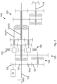
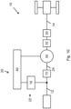
- FIG. 1 A design of the transmission system 10 is shown.
- Drive power is transmitted from a drive, usually an internal combustion engine, to an input shaft 12.
- the drive machine can also be a hydraulic motor.
- the input shaft also serves to supply drive power for a power take-off shaft or PTO and is designed as a continuous shaft.
- the input-side electric machine 16 is electrically connected to the output-side electric machine 18 and to a transmission system control 40.
- the output-side electric machine 18 is operatively connected to the modulating ring 56 of the magnetic-electric epicyclic gear stage 50, which in turn interacts with the inner rotor 52.
- the mechanical transmission branch 24 is formed from the continuous input shaft 12.
- the modulating ring 56 is connected by means of a hollow shaft which surrounds the input shaft 12.
- the hollow shaft is designed to be connected to the manual transmission 30 and to a first gear pair F1 or a further gear pair F2 by means of a powershift clutch.
- the gear pairs F1 and F2 form the manual transmission 30 of the transmission system 10.
- the gear pairs F1 and F2 transfer the drive power to the output shaft 14, which in turn is used to transmit it to the output.
- the second gear pair F2 is not connected in a rotationally fixed manner to the output shaft 14, but is connected in a rotationally fixed manner to it by switching via a coupling element.
- the first gear pair F1 is connected in a rotationally fixed manner to the output shaft 14, so that when the coupling element is freewheeling and the powershift clutch in the manual transmission is in the corresponding position, the drive torque is passed via the first gear pair F1.
- Another gear pair R for a reverse gear can be connected to the second gear pair F2.
- the direction of rotation is reversed using an additional intermediate shaft between the input shaft 12 and the output shaft 14.
- the gear pair R is not connected to the output shaft 14 in a rotationally fixed manner and is switched using the coupling element.
- the first gear pair F1, the second gear pair F2 or the reverse gear R is connected to the output.
- the drive power is divided in the power-split transmission section 20 by means of The input-side electric machine 16 is controlled and a corresponding portion is converted into electrical power. The remaining mechanical portion is passed through the input shaft 12 or remains in it.
- the electrical power is controlled by means of the transmission system control 40 and the output-side electric machine 18 is controlled and supplied with electrical power.
- the torque generated and the speed are influenced by controlling the current and voltage, so that with the action of the modulating ring 56 and the inner rotor 52, an outgoing speed and an outgoing torque are set at the modulating ring 56.
- the remaining power in the input shaft is sent to the PTO, while the remaining power is sent to the manual transmission.
- Figure 4 shows a transmission system 10 according to the invention Figure 1 , whereby the design does not have a separate reverse gear.
- the drive torque is divided between the mechanical transmission branch 24 and the variable transmission branch 22, which consists of the first and second electric machines 16 and 18.
- the second electric machine 18 is part of the magnetic-electric planetary gear stage 50.
- the manual transmission 30 is formed following in the power path. From this, the drive power is directed to one or more axles of the vehicle and finally to the output.
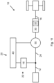
- Figure 12 shows an embodiment with the reverse gear 32 in the power path between the first electric machine 16 and the magnetic-electric epicyclic gear stage 50.
Landscapes
- Engineering & Computer Science (AREA)
- Mechanical Engineering (AREA)
- Chemical & Material Sciences (AREA)
- Combustion & Propulsion (AREA)
- Transportation (AREA)
- Power Engineering (AREA)
- General Engineering & Computer Science (AREA)
- Structure Of Transmissions (AREA)
- Dynamo-Electric Clutches, Dynamo-Electric Brakes (AREA)
- Connection Of Motors, Electrical Generators, Mechanical Devices, And The Like (AREA)
- Arrangement Of Transmissions (AREA)
Description
- Die vorliegende Erfindung betrifft ein Getriebesystem für eine landwirtschaftliche Maschine. Die
DE102015114559A1 offenbart ein Getriebesystem mit einem leistungsverzweigten Getriebeabschnitt und einem Schaltgetriebe, wobei der leistungsverzweigte Getriebeabschnitt wenigstens einen variablen Getriebezweig und einen mechanischen Getriebezweig aufweist. - Ein Getriebesystem besteht üblicherweise aus einer Eingangswelle, einem schaltbaren Getriebe und einer Ausgangswelle. Getriebesysteme verändern die eingeleitete Antriebsleistung in Drehmoment und Drehzahl und leiten diese an den Abtrieb weiter.
- Ein Getriebesystem kann Schaltgetriebe oder Stufenlosgetriebe als Komponenten verwenden. Schaltgetriebe werden durch lastschaltbare Kupplungen realisiert, die unterschiedliche, im Eingriff stehende Zahnradstufen miteinander verbinden. Dieser Schaltzeitpunkt, auch Lastschaltpunkt genannt, führt zu einer Geschwindigkeitsänderung der im Eingriff stehenden Getriebesystemkomponenten, zu Geräuschentwicklung, Verschleiß und einem unterbrochene Leistungsfluss.
- Das Getriebesystem kann alternativ als Stufenlosgetriebe umgesetzt werden. Dies ist mittels hydraulischer Variatoren realisiert, um höhere Antriebsleistung sicher umwandeln zu können. Hierbei wird eingangsseitig des Stufenlosgetriebes mittels Hydrostaten ein Teil der Antriebsleistung in hydraulische Leistung umgewandelt. Mittels der Variatoren kann der Anteil der hydraulischen Leistung variiert werden. Ausgangsseitig wird die hydraulische Energie wieder in mechanische Energie umgewandelt. Meist haben Stufenlosgetriebe eine Ausgangswelle, um den Aufbau zu vereinfachen. Dies erfordert zum Schaltzeitpunkt des Getriebesystems gleichzeitig mit dem Gangwechsel im nachgeschalteten Getriebe eine Drehzahländerung an der Variatorausgangswelle. Dieser Vorgang beansprucht Zeit, die den Schaltvorgang verlangsamt und zu einer Trägheit des Getriebesystems führt.
- Als Möglichkeit kann das Getriebesystem mit einem Stufenlosgetriebe mit zwei Variatorausgangswellen ausgestattet sein. Hierbei kann auf einen gleichzeitigen Drehzahlwechsel mit dem Schaltvorgang verzichtet werden. Diese Art von Aufbau für zu einer gesteigerten Komplexität, bedingt durch den zweiten Variatorausgang zusammen mit höhere Bauteileanzahl. Insgesamt weisen solche Getriebesysteme einen erhöhten Wartungsaufwand auf, zusammen mit einem erhöhten Verschleiß und stärkerer Geräuschentwicklung.
- Die vorliegende Erfindung stellt ein Getriebesystem zur Verfügung, dass die angesprochenen Probleme überwindet.
- Das erfindungsgemäße Getriebesystem ist geeignet für Betrieb mit einer Antriebsmaschine, und weist eine Eingangswelle für die Antriebsleitung auf, wenigstens eine Ausgangswelle für die Abgabe an einen Antrieb, einen leistungsverzweigten Getriebeabschnitt, ein Schaltgetriebe, eine Getriebesystemsteuerung, wobei der leistungsverzweigte Getriebeabschnitt wenigstens einen variablen Getriebezweig und einen mechanischen Getriebezweig aufweist, und der variable Zweig eingangs- und ausgangsseitig jeweils wenigstens eine Elektromaschine für den Generator und Motorbetrieb aufweist, die elektrisch miteinander verbunden sind, wobei die Antriebsleistung durch den mechanischen und variablen Zweig aufgeteilt und geleitet wird, und mit einer eingangsgekoppelten magnetisch elektrischen Umlaufgetriebestufe, die den variablen Zweig und mechanischen Zweig zusammenführt, mit einem inneren Rotor, einem äußeren Stator und einem modulierenden Ring, und die magnetisch elektrische Umlaufgetriebestufe derart von der zweiten Elektromaschine ansteuerbar ist, dass die Ausgangswelle des Getriebesystems entgegen der Drehrichtung an einer Eingangswelle rotiert, wodurch ein Vorwärts- und Rückwärtsbetrieb des Getriebesystems durchführbar ist.
- Bei dem erfindungsgemäßen Getriebesystem und der Verwendung von Elektromaschinen im variablen Zweig zusammen mit einer magnetisch elektrischen Umlaufgetriebestufe, wird im Schaltpunkt des Getriebes gleichzeitig die Erregerfrequenz in den Statorwicklungen der magnetisch elektrischen Umlaufgetriebestufe umgeschaltet. Durch diese Schaltung findet eine Veränderung der Drehzahl einer Zwischenwelle statt. Hierbei wird jedoch nur ein geringes Drehmoment benötigt, so dass ein schnellerer Schaltvorgang des Getriebesystems ermöglicht wird im Vergleich zum Stand der Technik. Die Schaltvorgänge reduzieren damit den Koordinierungsaufwand der Bedienperson und verkürzen die Dauer des Schaltvorgangs. Hierbei wird das Fahrzeug geringeren Geschwindigkeitsschwankungen ausgesetzt, so dass ein erhöhter Fahrkomfort sichergestellt wird.
- In einer weiteren Ausführung wird die magnetisch elektrische Umlaufgetriebestufe derart von der zweiten Elektromaschine angesteuert, dass eine Ausgangswelle der magnetisch elektrischen Umlaufgetriebestufe in Gegenrichtung zur Eingangswelle des Getriebesystems rotiert.
- Die Ansteuerung der magnetisch elektrischen Umlaufgetriebestufe ermöglicht eine Überlagerung der Drehzahl und Richtung der Eingangswelle mit einem Ausgang der magnetisch elektrischen Umlaufgetriebestufe, so dass eine resultierende Ausgangsdrehzahl und Drehrichtung der Ausgangswelle entgegengesetzt zur Eingangswelle eingestellt wird. Ein zusätzlicher Rückwärtsgang kann entfallen und der gesamte Aufbau des Getriebesystems wird vereinfacht, wodurch die benötigte Teileanzahl und entsprechende Herstellungs- und Einbauvorgänge reduziert werden.
- Bei einer weiteren Ausbildung ist ein zusätzliches Modul zur Drehrichtungsumkehr zwischen der ersten Elektromaschine und der magnetisch elektrischen Umlaufgetriebestufe im Leistungsfluss vorgesehen.
- Das Modul zur Drehrichtungsumkehr kann separat ausgeführt werden vom Schaltgetriebe. Damit wird die Komplexität reduziert. Das Modul kann für ein geringeres Drehmoment ausgelegt werden, wodurch Produktionsaufwand und Teilegewicht reduziert wird.
- Bei einer Weiterbildung ist ein Gang des Schaltgetriebes ein zusätzlicher Rückwärtsgang.
- Mit der Integration des Rückwärtsgangs in das Schaltgetriebe wird die Kompatibilität zu gewöhnlichen Schaltgetrieben hergestellt. Der notwendige Bauraum für den leistungsverzweigten Getriebeabschnitt wird reduziert.
- In einer Ausführung ist ein zusätzliches Modul zur Drehrichtungsumkehr zwischen der magnetisch elektrischen Umlaufgetriebestufe und dem Schaltgetriebe im Leistungsfluss vorgesehen.
- Die separate Anordnung erleichtert die Zugänglichkeit des Moduls zu Instandhaltungszwecken.
- Bei einer Weiterbildung ist ein zusätzliches Modul zum seriell elektrischen Anfahren im Leistungsfluss vorgesehen.
- Das Modul ermöglicht das Anfahren des Fahrzeugs durch den elektrischen Leistungszweig, der dem Leistungsfluss über die zwei Elektromaschinen entspricht bei gleichzeitiger Abschaltung des mechanischen Leistungszweigs. Durch das rein elektrische Anfahren kann ein hohes Drehmoment an den Abtrieb geleitet werden. Dies ist besonders bei Anfahren mit einem hohen Zugmoment des Fahrzeuges von Vorteil, da hier bei geringer Fahrgeschwindigkeit hohe Zugkräfte aufgebracht werden müssen. Mittels des Moduls ist dies sichergestellt.
- In einer Ausführung ist das Modul zum seriell elektrischen Anfahren zwischen der Eingangswelle des Getriebesystems und der magnetisch elektrischen Umlaufgetriebestufe im Leistungsfluss vorgesehen.
- Aufgrund des Moduls findet eine mechanische Entkopplung des primären Antriebs vom Abtrieb des Fahrzeugs statt. Die Antriebsleistung wird in elektrische Leistung umgewandelt und an den Abtrieb geleitet. Durch das Vorsehen im Leistungsfluss vor der magnetisch elektrischen Umlaufgetriebestufe kann das Modul innerhalb des leistungsverzweigten Getriebeabschnitts angeordnet werden. Die Elektromaschinen können hier für die Umwandlung und Abgabe verwendet werden.
- Bei einer Ausbildung ist das Modul zum seriell elektrischen Anfahren im Leistungsfluss zwischen der ersten Elektromaschine und der magnetisch elektrischen Umlaufgetriebestufe vorgesehen.
- Durch das Vorsehen im Leistungsfluss vor der magnetisch elektrischen Umlaufgetriebestufe kann das Modul innerhalb des leistungsverzweigten Getriebeabschnitts angeordnet werden. Die Elektromaschinen können hier für die Umwandlung und Abgabe verwendet werden.
- In einer Weiterbildung ist das Modul zum seriell elektrischen Anfahren im Leistungsfluss zwischen dem Modul zur Drehrichtungsumkehr und der magnetisch elektrischen Umlaufgetriebestufe vorgesehen.
- Die Erfindung wird weiterhin anhand der folgenden Figuren beschrieben. Dabei zeigt:
-
Fig. 1 einen Aufbau des erfindungsgemäßen Getriebesystems; -
Fig. 2 einen Aufbau aus dem Stand der Technik; -
Fig. 3 einen weiteren Aufbau des erfindungsgemäßen Getriebesystems; -
Fig. 4 einen weiteren schematischen Aufbau des Getriebesystems; -
Fig. 5 einen weiteren schematischen Aufbau des Getriebesystems; -
Fig. 6 einen weiteren schematischen Aufbau des Getriebesystems; -
Fig. 7 einen weiteren schematischen Aufbau des Getriebesystems; -
Fig. 8 einen weiteren schematischen Aufbau des Getriebesystems; -
Fig. 9 einen weiteren schematischen Aufbau des Getriebesystems; -
Fig. 10 einen weiteren schematischen Aufbau des Getriebesystems; -
Fig. 11 einen weiteren schematischen Aufbau des Getriebesystems; -
Fig. 12 einen weiteren schematischen Aufbau des Getriebesystems. - In
Figur 1 ist eine Ausführung des Getriebesystems 10 dargestellt. Von einem Antrieb, meist ein Verbrennungsmotor, wird Antriebsleistung auf eine Eingangswelle 12 übertragen. Die Antriebsmaschine kann jedoch auch ein hydraulischer Motor sein. Mit der Eingangswelle 12 ist drehfest ein Rotor der eingangsseitigen Elektromaschine verbunden, sowie der innere Rotor 52 der magnetisch elektrischen Umlaufgetriebestufe 50. Die Eingangswelle dient gleichzeitig der Versorgung von Antriebsleistung für eine Zapfwelle oder PTO und ist als durchgehende Welle ausgeführt. - Die eingangsseitige Elektromaschine 16 ist elektrisch mit der ausgangsseitigen Elektromaschine 18 verbunden und mit einer Getriebesystemsteuerung 40. Die ausgangsseitigen Elektromaschine 18 ist in Wirkverbindung mit dem modulierenden Ring 56 der magnetisch elektrischen Umlaufgetriebestufe 50, welcher wiederrum mit dem inneren Rotor 52 zusammenwirkt. Die eingangsseitige und ausgangsseitige Elektromaschine stellt zusammen mit der magnetisch elektrischen Umlaufgetriebestufe den variablen Getriebezweig 24 dar, und zusammen mit der Eingangswelle den leistungsverzweigten Getriebeabschnitt 20. Der mechanische Getriebezweig 24 wird aus der durchgehenden Eingangswelle 12 gebildet.
- Im Leistungsfluss daran anschließend ist der modulierende Ring 56 mittels einer Hohlwelle verbunden, welche die Eingangswelle 12 umgibt. Die Hohlwelle ist in Verbindung mit dem Schaltgetriebe 30 und mittels einer Lastschaltkupplung mit einem ersten Zahnradpaar F1 oder einem weiteren Zahnradpaar F2 verbindbar ausgeführt. Die Zahnradpaare F1 und F2 bilden das Schaltgetriebe 30 des Getriebesystems 10. Die Zahnradpaare F1 und F2 übertragen die Antriebsleistung auf die Ausgangswelle 14, welche wiederrum zur Weiterleitung an den Abtrieb dient. Das zweite Zahnradpaar F2 ist nicht drehfest mit der Ausgangswelle 14 verbunden, sondern wird über ein Kopplungselement durch Schalten drehfest mit dieser verbunden. Das erste Zahnradpaar F1 ist drehfest mit der Ausgangswelle 14 verbunden, so dass bei einem Freilauf des Kopplungselements und bei entsprechender Stellung der Lastschaltkupplung im Schaltgetriebe das Antriebsmoment über das erste Zahnradpaar F1 geleitet wird.
- Mit dem zweiten Zahnradpaar F2 kann ein weiteres Zahnradpaar R für einen Rückwärtsgang verbunden sein. Mittels einer zusätzlichen Zwischenwelle zwischen der Eingangswelle 12 und der Ausgangswelle 14 erfolgt die Drehrichtungsumkehr. Auf der Ausgangswelle ist das Zahnradpaar R nicht drehfest mit der Ausgangswelle 14 verbunden und wird mittels des Kopplungselements geschaltet. Es ist somit je nach Stellung des Kopplungselements und der Lastschaltkupplung das erste Zahnradpaar F1, das zweite Zahnradpaar F2 oder der Rückwärtsgang R an den Abtrieb gelegt.
- Die Antriebsleistung wird im leistungsverzweigten Getriebeabschnitt 20 aufgeteilt mittles Ansteuerung der eingangsseitigen Elektromaschine 16 und ein entsprechender Anteil in elektrische Leistung umgewandelt. Der verbleibende mechanische Anteil wird durch die Eingangswelle 12 geleitet bzw. verbleibt in dieser. Die elektrische Leistung wird mittels der Getriebesystemsteuerung 40 kontrolliert und die ausgangsseitige Elektromaschine 18 angesteuert und mit elektrischer Leistung versorgt. Durch die Kontrolle von Strom und Spannung wird das erzeugte Drehmoment und die Drehzahl beeinflusst, so dass sich mit der Einwirkung des modulierenden Rings 56 und des inneren Rotors 52 eine abgehende Drehzahl und ein abgehendes Drehmoment am modulierenden Ring 56 einstellt.
- Der Anteil an verbleibender Leistung in der Eingangswelle wird an die Zapfwelle geleitet, während der weitere Anteil an das Schaltgetriebe geleitet wird.
- Zu einem Schaltzeitpunkt, bei entsprechendem Ansteuern durch die Getriebesystemsteuerung erfolgt ein Schließen einer der Lastschaltkupplungen für F1 oder F2, während die jeweils andere Lastschaltkupplung geöffnet wird. Gleichzeitig erfolgt ein Umschalten des Kopplungselements auf der Ausgangswelle 14. Durch den Wechsel des Leistungspfades und der daraus resultierenden Drehzahl sowie dem Drehmoment, würde ohne die Erfindung das Getriebesystem eine Änderung des Trägheitsmoments, so dass diese Änderung von der Bedienperson spürbar ist. Gleichzeitig erfährt das Fahrzeug eine Geschwindigkeitsänderung.
- Um dies zu verhindern ist erfindungsgemäß vorgesehen, dass gleichzeitig mit den Schaltvorgängen im Schaltgetriebe 30 eine Anpassung der elektrischen Antriebsleistung erfolgt, derart, dass durch die Getriebesystemsteuerung 40 eine Änderung der Erregerfrequenz der Wicklungen im äußeren Stator 54 der magnetisch elektrischen Umlaufgetriebestufe 54 erfolgt. Die Änderung selbst verursacht kein Drehmoment oder Drehzahländerung, so dass die Veränderung des Trägheitsmoments des Getriebesystems sehr klein gehalten wird. Durch diese Verringerung durchläuft das Fahrzeug keine wahrnehmbare Geschwindigkeitsänderung.
- Das Eingangsmoment liegt über die Eingangswelle 12 gleichzeitig an der ersten Elektromaschine 16 und an dem inneren Rotor 52 an. Die erste Elektromaschine 16 wandelt dieses in elektrische Leistung um, wobei die Ansteuerung über die Getriebesystemsteuerung 40 erfolgt. Die elektrische Leistung wird über die zweite Elektromaschine 18 mit einem äußeren Stator 54 abgegeben. Durch eine Änderung der Erregerfrequenz können unterschiedliche Drehzahlen in der magnetisch elektrischen Umlaufgetriebestufe eingestellt werden. Die anliegende Leistung am inneren Rotor 52, als auch die anliegende Leistung am äußeren Stator 54 bedingt die sich anstellende Leistung am modulierenden Ring 56. Die Leistung wird über den modulierenden Ring 56 an das Schaltgetriebe 30 abgegeben und durch Schalten der jeweiligen Kupplungen über die Zahnradpaare F1, F2 oder R geleitet.
- Insgesamt ist das Getriebesystem in der Lage, am Schaltzeitpunkt den sich einstellenden Impuls ein gleichzeitiges Ändern der Drehzahl in der magnetisch elektrischen Umlaufgetriebestufe 50 auszugleichen und einen harmonischen, ruckfreien Betrieb während Schaltvorgängen zu erhalten.
- Das Getriebesystem 10 kann gleichzeitig das rein elektrische Anfahren ermöglichen, da keine mechanische Verbindung zwischen dem Antrieb und dem Abtrieb besteht. Durch das Vorhalten von Batteriespeicher und der Einspeisung von zusätzlicher elektrischer Energie in die zweite Elektromaschine 18 kann so ein reines elektrisches Anfahren umgesetzt werden. Dies erfolgt im Modul zum seriell elektrischen Anfahren 70. Dies ist besonders von Vorteil bei einer hohen Anhängelast, die bei geringen Fahrgeschwindigkeiten normalerweise eine starke Untersetzung erfordert, um anzufahren.
-
Figur 2 beschreibt ein bekanntes leistungsverzweigtes Getriebesystem aus dem Stand der Technik, das einen variablen Zweig aufweist mit zwei Ausgängen 1 und 2. - Die Antriebsleistung wird über die Eingangswelle 112 zu einem ersten Zahnrad G1 geleitet und mittels der weiteren Zahnräder G2 und Gzw bzw. G3 jeweils an eine erste Elektromaschine 116 und an einen Rückwärtsgang 132 geleitet.
- Der variable Leistungsanteil wird zu einer zweiten Elektromaschine 118 elektrisch übertragen und mittels einer magnetische elektrischen Umlaufgetriebestufe 150 wieder mit der mechanischen Leistung vereint. Im Unterschied zur vorliegenden Erfindung weist das Getriebesystem nach dem Stand der Technik zwei Ausgänge OUT1 und OUT2 auf, die je nach Anwendung mittels einer Lastschaltkupplung mit dem Abtrieb verbunden werden können. Daran anschließend wird die Antriebsleistung durch ein Schaltgetriebe 130 geleitet, wobei mittels zwei Kupplungen unterschiedliche Übersetzungen festgelegt werden.
- Die Lösung mittels zwei Ausgängen nach dem Leistungsverzweigten Getriebe ermöglicht das Umschalten der Ausgänge zeitgleich zum Umschalten der Lastschaltkupplungen im Schaltgetriebe 130. Hierdurch wird zusammen mit der Änderung der Drehzahl und des Drehmoments im Schaltgetriebe 130 die Drehzahl und das Drehmoment am Ausgang des leistungsverzweigen Getriebeabschnitts 120 geändert. Dies führt zu einem Ausgleich des Impulses im Schaltzeitpunkt. Im Unterschied zur vorliegenden Erfindung ist der Aufbau des Getriebesystems 100 wesentlich komplexer. Es müssen zwei Ausgänge des leistungsverzweigten Getriebeabschnitts vorgehalten werden, zusammen mit zwei Lastschaltkupplungen und zwei zusätzlichen Planetenstufen. Parallel ist die Steuerung des Getriebesystems 130 so ausgelegt, dass nur zwischen zwei unterschiedlichen Drehzahlverhältnissen umgeschaltet werden kann. Insgesamt führt dies zu einer höheren Fertigungskomplexität, einer höheren Bauteilanzahl und einem gesteigerten Gewicht.
-
Figur 3 zeigt ein weiteres Ausführungsbeispiel des erfindungsgemäßen Getriebesystems. Dabei wird die erste Elektromaschine 16 über eine Welle eines Zahnrades angetrieben, das mit einer konstanten Übersetzung mit dem Eingangsdrehmoment versorgt wird. Von der Eingangswelle 12 wird die Antriebsleistung in den Planetenträger eines Umlaufgetriebes eingeleitet. Dieses hat einen verblockbaren Außenring und weist eine Lastschaltkupplung auf, mit welcher der Planetenträger mit der Sonne koppelbar ist. Der Ausgang des Planetengetriebes erfolgt ebenfalls über die Sonne, so dass die Antriebsleistung weiter parallel über die Eingangswelle 12 und die Sonnenwelle erfolgt. Weiter unterhalb im Leistungspfad erfolgt die Einleitung des variablen Leistungsanteils mittels der zweiten Elektromaschine 18 und einem weiteren Sonnenrad der magnetisch elektrischen Umlaufgetriebestufe 50, wobei der modulierbare Ring 56 mittels einer weiteren Lastschaltkupplung mit dem inneren Rotor in der Funktion als Sonnenrad koppelbar ist. Hierbei erfolgt zwischen der ersten und zweiten Elektromaschine 16 und 18 eine Regelung des variablen Leistungsanteils. Ein anschließendes Schaltgetriebe 30 mit einer weiteren parallelen Welle zum Abtrieb schließt sich an. Das Schaltgetriebe verfügt über zwei Zahnradpaarungen F1 und F2 die mittels Lastschaltkupplungen mit der Sonnenwelle koppelbar sind. Die Eingangswelle 12 dient der Versorgung der Zapfwelle oder PTO. Zusätzlich ist ein weiterer untersetzter Gang als Langsamfahrgang oder Creep vorgesehen. - Der Rückwärtsgang im Getriebesystem 10 wird über das Schließen oder Öffnen der Lastschaltkupplung CFwd bereitgestellt, wodurch eine Drehrichtungsumkehr am Sonnenrad bzw. an der Sonnenwelle des Planetengetriebes erfolgt.
-
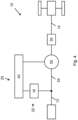
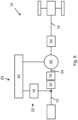
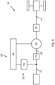
Figuren 4 bis 12 zeigen einen schematischen Aufbau von weiteren Ausführungen des erfindungsgemäßen Getriebesystems 10. Die einzelnen Komponenten entsprechen in der Ausbildung denen derFiguren 1 und3 . -
Figur 4 zeigt ein erfindungsgemäßes Getriebesystem 10 nachFigur 1 , wobei die Ausführung keinen gesonderten Rückwärtsgang aufweist. Das Antriebsmoment wird aufgeteilt zwischen dem mechanischen Getriebezweig 24 und dem variablen Getriebezweig 22, der aus der ersten und zweiten Elektromaschine 16 und 18 besteht. Die zweite Elektromaschine 18 ist Bestandteil der magnetisch elektrischen Umlaufgetriebestufe 50. Im Leistungspfad folgend ist das Schaltgetriebe 30 ausgebildet. Von diesem ausgehend wird die Antriebsleistung in eine oder mehrere Achsen des Fahrzeugs und abschließend an den Abtrieb geleitet. -
Figur 5 zeigt eine Ausführung, wobei das Getriebesystem 10 zusätzlich einen Rückwärtsgang 32 aufweist, der im Leistungspfad zwischen dem Schaltgetriebe 30 und den Fahrzeugachsen vorgesehen ist. -
Figur 6 zeigt eine Ausbildung, bei welcher der Rückwärtsgang 32 im Bereich zwischen der ersten Elektromaschine 16 und der magnetisch elektrischen Umlaufgetriebestufe 50 im Leistungspfad ausgebildet ist. Zusätzlich ist ein Modul zum seriell elektrischen Anfahren 70 im Leistungspfad vorgesehen, das ein Anfahren des Fahrzeugs ohne direkte mechanische Kopplung des Antriebes mit dem Abtrieb ermöglicht. -
Figur 7 beschreibt eine Ausführung, in welcher der Rückwärtsgang 32 im Leistungspfad zwischen der magnetisch elektrischen Umlaufgetriebestufe 50 und dem Schaltgetriebe 30 ausgebildet ist. -
Figur 8 zeigt eine Ausführung, in welcher das Modul zum seriell elektrischen Anfahren 70 im Leistungspfad zwischen der ersten Elektromaschine 16 und der magnetisch elektrischen Umlaufgetriebestufe 50 vorgesehen ist. Weiterhin ist der Rückwärtsgang 32 zwischen dem Schaltgetriebe 30 und den Fahrzeugachsen ausgebildet. -
Figur 9 beschreibt eine Ausführung mit dem Modul zum seriell elektrischen Anfahren 70 gemäßFigur 8 , wobei auf einen Rückwärtsgang verzichtet wurde. Dieser wird über die magnetisch elektrische Umlaufgetriebestufe 50 ausgeführt, so dass eine Drehrichtungsumkehr am Ausgang der magnetisch elektrischen Umlaufgetriebestufe 50 anliegt. -
Figur 10 zeigt eine weitere Ausführung, wobei das Modul zum seriell elektrischen Anfahren 70 im Leistungspfad zwischen der ersten Elektromaschine 16 und der magnetisch elektrischen Umlaufgetriebestufe 50 ausgebildet ist. Der Rückwärtsgang 32 ist im Leistungspfad zwischen der magnetisch elektrischen Umlaufgetriebestufe 50 und dem Schaltgetriebe 30 vorgesehen. -
Figur 11 zeigt eine Ausführung, bei welcher der Rückwärtsgang 32 innerhalb des Schaltgetriebes 30 ausgebildet ist. -
Figur 12 zeigt eine Ausführung mit dem Rückwärtsgang 32 im Leistungspfad zwischen der ersten Elektromaschine 16 und der magnetisch elektrischen Umlaufgetriebestufe 50.
Claims (9)
- Getriebesystem (10)geeignet für Betrieb mit einer Antriebsmaschine, aufweisend eine Eingangswelle (12) für die Antriebsleitung,wenigstens eine Ausgangswelle (14) für die Abgabe an einen Antrieb, einen leistungsverzweigten Getriebeabschnitt (20),ein Schaltgetriebe (30),eine Getriebesystemsteuerung (40),wobei der leistungsverzweigte Getriebeabschnitt (20) wenigstens einen variablen Getriebezweig (22) und einen mechanischen Getriebezweig (24) aufweist, und der variable Getriebezweig (22) eingangs- und ausgangsseitig jeweils wenigstens eine erste und zweite Elektromaschine (16, 18) für den Generator und Motorbetrieb aufweist, die elektrisch miteinander verbunden sind,wobei die Antriebsleistung durch den mechanischen und variablen Getriebezweig (22, 24) aufgeteilt und geleitet wird, undmit einer eingangsgekoppelten magnetisch elektrischen Umlaufgetriebestufe (50), die den variablen Getriebezweig (22) und mechanischen Getriebezweig (24) zusammenführt, miteinem inneren Rotor (52), einem äußeren Stator (54) und einem modulierenden Ring (56), dadurch gekennzeichnet, dass die magnetisch elektrische Umlaufgetriebestufe (50) derart von der zweiten Elektromaschine (18) ansteuerbar ist, dass die Ausgangswelle (14) des Getriebesystems (10) entgegen der Drehrichtung an einer Eingangswelle (12) rotiert, wodurch ein Vorwärts- und Rückwärtsbetrieb des Getriebesystems (10) durchführbar ist.
- Getriebesystem (10) nach Anspruch 1, dadurch gekennzeichnet, dass die magnetisch elektrische Umlaufgetriebestufe (50) derart von der zweiten Elektromaschine (18) angesteuert wird, dass eine Ausgangswelle der magnetisch elektrischen Umlaufgetriebestufe (50) in Gegenrichtung zur Eingangswelle (12) des Getriebesystems (10) rotiert.
- Getriebesystem (10) nach Anspruch 1, dadurch gekennzeichnet, dass ein zusätzliches Modul zur Drehrichtungsumkehr (60) zwischen der ersten Elektromaschine (16) und der magnetisch elektrischen Umlaufgetriebestufe (50) im Leistungsfluss vorgesehen ist.
- Getriebesystem (10) nach Anspruch 1, dadurch gekennzeichnet, dass ein Gang des Schaltgetriebes (30) ein zusätzlicher Rückwärtsgang (32) ist.
- Getriebesystem (10) nach Anspruch 1, dadurch gekennzeichnet, dass ein zusätzliches Modul zur Drehrichtungsumkehr (60) zwischen der magnetisch elektrischen Umlaufgetriebestufe (50) und dem Schaltgetriebe (30) im Leistungsfluss vorgesehen ist.
- Getriebesystem (10) nach einem der vorangehenden Ansprüche, wobei ein weiteres zusätzliches Modul zum seriell elektrischen Anfahren (70) im Leistungsfluss vorgesehen ist.
- Getriebesystem (10) nach Anspruch 6, dadurch gekennzeichnet, dass das weitere zusätzliche Modul zum seriell elektrischen Anfahren (70) zwischen der Eingangswelle (12) des Getriebesystems (10) und der magnetisch elektrischen Umlaufgetriebestufe (50) im Leistungsfluss vorgesehen ist.
- Getriebesystem (10) nach einem Ansprüche 6 oder 7, dadurch gekennzeichnet, dass das weitere zusätzliche Modul zum seriell elektrischen Anfahren (70) im Leistungsfluss zwischen der ersten Elektromaschine (16) und der magnetisch elektrischen Umlaufgetriebestufe (50) vorgesehen ist.
- Getriebesystem (10) nach Anspruch 3, dadurch gekennzeichnet, dass das Modul zum seriell elektrischen Anfahren (70) im Leistungsfluss zwischen dem Modul zur Drehrichtungsumkehr (60) und der magnetisch elektrischen Umlaufgetriebestufe (50) vorgesehen ist.
Priority Applications (1)
| Application Number | Priority Date | Filing Date | Title |
|---|---|---|---|
| EP23185453.0A EP4246014A3 (de) | 2020-07-29 | 2021-07-12 | Getriebesystem |
Applications Claiming Priority (1)
| Application Number | Priority Date | Filing Date | Title |
|---|---|---|---|
| DE102020119984.8A DE102020119984A1 (de) | 2020-07-29 | 2020-07-29 | Getriebesystem |
Related Child Applications (2)
| Application Number | Title | Priority Date | Filing Date |
|---|---|---|---|
| EP23185453.0A Division EP4246014A3 (de) | 2020-07-29 | 2021-07-12 | Getriebesystem |
| EP23185453.0A Division-Into EP4246014A3 (de) | 2020-07-29 | 2021-07-12 | Getriebesystem |
Publications (2)
| Publication Number | Publication Date |
|---|---|
| EP3945665A1 EP3945665A1 (de) | 2022-02-02 |
| EP3945665B1 true EP3945665B1 (de) | 2025-03-05 |
Family
ID=76890813
Family Applications (2)
| Application Number | Title | Priority Date | Filing Date |
|---|---|---|---|
| EP23185453.0A Pending EP4246014A3 (de) | 2020-07-29 | 2021-07-12 | Getriebesystem |
| EP21184936.9A Active EP3945665B1 (de) | 2020-07-29 | 2021-07-12 | Getriebesystem |
Family Applications Before (1)
| Application Number | Title | Priority Date | Filing Date |
|---|---|---|---|
| EP23185453.0A Pending EP4246014A3 (de) | 2020-07-29 | 2021-07-12 | Getriebesystem |
Country Status (3)
| Country | Link |
|---|---|
| US (1) | US11691497B2 (de) |
| EP (2) | EP4246014A3 (de) |
| DE (1) | DE102020119984A1 (de) |
Families Citing this family (4)
| Publication number | Priority date | Publication date | Assignee | Title |
|---|---|---|---|---|
| US12115858B2 (en) | 2022-07-05 | 2024-10-15 | Deere & Company | Adjustable drop transmission assembly for a work vehicle |
| DE102023102489A1 (de) | 2023-02-01 | 2024-08-01 | Deere & Company | Antriebsstrang und Fahrzeug |
| DE102023112521A1 (de) | 2023-05-11 | 2024-11-14 | Deere & Company | Getriebeanordnung und landwirtschaftliches Zugfahrzeug |
| EP4589171A1 (de) * | 2024-01-17 | 2025-07-23 | Deere & Company | Getriebeanordnung und landwirtschaftliches zugfahrzeug |
Citations (1)
| Publication number | Priority date | Publication date | Assignee | Title |
|---|---|---|---|---|
| DE102015114559A1 (de) * | 2014-09-02 | 2016-03-03 | Denso Corporation | Drehmaschinensystem mit zwei integrierten wellen |
Family Cites Families (9)
| Publication number | Priority date | Publication date | Assignee | Title |
|---|---|---|---|---|
| JP4243304B2 (ja) | 2006-10-25 | 2009-03-25 | 本田技研工業株式会社 | 動力装置 |
| JP4693865B2 (ja) * | 2007-08-27 | 2011-06-01 | 株式会社豊田中央研究所 | 動力伝達装置 |
| JP5589567B2 (ja) | 2009-06-03 | 2014-09-17 | 株式会社豊田中央研究所 | 動力伝達装置 |
| JP2013166409A (ja) | 2012-02-14 | 2013-08-29 | Toyota Motor Corp | 車両用駆動装置 |
| DE102017208985A1 (de) | 2017-05-29 | 2018-11-29 | Deere & Company | Magnetisches Umlaufgetriebe mit variierbarem Drehmoment |
| DE102017219758A1 (de) * | 2017-11-07 | 2019-05-09 | Deere & Company | Differenzialanordnung |
| CN108340766B (zh) | 2018-01-03 | 2021-06-04 | 北京理工大学 | 混合动力系统、车辆及其控制方法 |
| DE102018200953A1 (de) * | 2018-01-22 | 2019-07-25 | Deere & Company | Fahrzeug mit einer Anordnung zur dynamischen Anpassung des Vorlaufs |
| DE102018204405A1 (de) | 2018-03-22 | 2019-09-26 | Deere & Company | Zapfwellengetriebe |
-
2020
- 2020-07-29 DE DE102020119984.8A patent/DE102020119984A1/de active Pending
-
2021
- 2021-07-06 US US17/305,350 patent/US11691497B2/en active Active
- 2021-07-12 EP EP23185453.0A patent/EP4246014A3/de active Pending
- 2021-07-12 EP EP21184936.9A patent/EP3945665B1/de active Active
Patent Citations (1)
| Publication number | Priority date | Publication date | Assignee | Title |
|---|---|---|---|---|
| DE102015114559A1 (de) * | 2014-09-02 | 2016-03-03 | Denso Corporation | Drehmaschinensystem mit zwei integrierten wellen |
Also Published As
| Publication number | Publication date |
|---|---|
| EP4246014A2 (de) | 2023-09-20 |
| US20220032763A1 (en) | 2022-02-03 |
| EP3945665A1 (de) | 2022-02-02 |
| DE102020119984A1 (de) | 2022-02-03 |
| EP4246014A3 (de) | 2023-11-08 |
| US11691497B2 (en) | 2023-07-04 |
Similar Documents
| Publication | Publication Date | Title |
|---|---|---|
| EP3945665B1 (de) | Getriebesystem | |
| EP3707411B1 (de) | Stufenloses leistungsverzweigungsgetriebe mit wenigstens vier fahrbereichen | |
| EP2914876B1 (de) | Doppelkupplungsgetriebe | |
| DE3026219A1 (de) | Antriebsaggregat mit einer antriebsmaschine und einem schwungrad | |
| DE102018213893A1 (de) | Kraftfahrzeuggetriebe, insbesondere für ein landwirtschaftliches oder kommunales Nutzfahrzeug, sowie Kraftfahrzeugantriebsstrang | |
| DE102018103185A1 (de) | Hybridachsgetriebe | |
| DE102014208712B3 (de) | Getriebe für einen Hybridantriebsstrang eines Fahrzeugs | |
| DE102017206413A1 (de) | Leistungsverzweigtes Stufenlosgetriebesystem | |
| DE102018213891B4 (de) | Kraftfahrzeuggetriebe, insbesondere für ein landwirtschaftliches oder kommunales Nutzfahrzeug, sowie Kraftfahrzeugantriebsstrang | |
| DE102017222717B4 (de) | Getriebe für ein Kraftfahrzeug | |
| DE102019200966B4 (de) | Leistungsverzweigtes Kraftfahrzeuggetriebe | |
| DE102015215070B4 (de) | Getriebesystem für einen Hybridantrieb eines Kraftfahrzeugs | |
| DE102021205940B4 (de) | Getriebe und Antriebsstrang für ein Kraftfahrzeug | |
| DE102018213876A1 (de) | Kraftfahrzeuggetriebe, insbesondere für ein landwirtschaftliches oder kommunales Nutzfahrzeug, sowie Kraftfahrzeugantriebsstrang | |
| DE102018213888A1 (de) | Kraftfahrzeuggetriebe, insbesondere für ein landwirtschaftliches oder kommunales Nutzfahrzeug, sowie Kraftfahrzeugantriebsstrang | |
| DE102018213890A1 (de) | Kraftfahrzeuggetriebe, insbesondere für ein landwirtschaftliches oder kommunales Nutzfahrzeug, sowie Kraftfahrzeugantriebsstrang | |
| DE102020202417B3 (de) | Leistungsverzweigtes stufenloses Getriebe | |
| AT526927B1 (de) | Reversiergetriebe | |
| DE102016206204B4 (de) | Leistungsverzweigter Antriebsstrang für eine Arbeitsmaschine | |
| DE102018213881A1 (de) | Kraftfahrzeuggetriebe, insbesondere für ein landwirtschaftliches oder kommunales Nutzfahrzeug, sowie Kraftfahrzeugantriebsstrang | |
| DE102018213883A1 (de) | Kraftfahrzeuggetriebe, insbesondere für ein landwirtschaftliches oder kommunales Nutzfahrzeug, sowie Kraftfahrzeugantriebsstrang | |
| DE102018213884A1 (de) | Kraftfahrzeuggetriebe, insbesondere für ein landwirtschaftliches oder kommunales Nutzfahrzeug, sowie Kraftfahrzeugantriebsstrang | |
| DE102018213892B4 (de) | Kraftfahrzeuggetriebe, insbesondere für ein landwirtschaftliches oder kommunales Nutzfahrzeug, sowie Kraftfahrzeugantriebsstrang | |
| DE102018213875A1 (de) | Kraftfahrzeuggetriebe, insbesondere für ein landwirtschaftliches oder kommunales Nutzfahrzeug, sowie Kraftfahrzeugantriebsstrang | |
| DE102018213887B4 (de) | Kraftfahrzeuggetriebe, insbesondere für ein landwirtschaftliches oder kommunales Nutzfahrzeug, sowie Kraftfahrzeugantriebsstrang |
Legal Events
| Date | Code | Title | Description |
|---|---|---|---|
| PUAI | Public reference made under article 153(3) epc to a published international application that has entered the european phase |
Free format text: ORIGINAL CODE: 0009012 |
|
| STAA | Information on the status of an ep patent application or granted ep patent |
Free format text: STATUS: THE APPLICATION HAS BEEN PUBLISHED |
|
| AK | Designated contracting states |
Kind code of ref document: A1 Designated state(s): AL AT BE BG CH CY CZ DE DK EE ES FI FR GB GR HR HU IE IS IT LI LT LU LV MC MK MT NL NO PL PT RO RS SE SI SK SM TR |
|
| STAA | Information on the status of an ep patent application or granted ep patent |
Free format text: STATUS: REQUEST FOR EXAMINATION WAS MADE |
|
| 17P | Request for examination filed |
Effective date: 20220802 |
|
| RBV | Designated contracting states (corrected) |
Designated state(s): AL AT BE BG CH CY CZ DE DK EE ES FI FR GB GR HR HU IE IS IT LI LT LU LV MC MK MT NL NO PL PT RO RS SE SI SK SM TR |
|
| STAA | Information on the status of an ep patent application or granted ep patent |
Free format text: STATUS: EXAMINATION IS IN PROGRESS |
|
| 17Q | First examination report despatched |
Effective date: 20230508 |
|
| GRAP | Despatch of communication of intention to grant a patent |
Free format text: ORIGINAL CODE: EPIDOSNIGR1 |
|
| STAA | Information on the status of an ep patent application or granted ep patent |
Free format text: STATUS: GRANT OF PATENT IS INTENDED |
|
| INTG | Intention to grant announced |
Effective date: 20241017 |
|
| GRAS | Grant fee paid |
Free format text: ORIGINAL CODE: EPIDOSNIGR3 |
|
| GRAA | (expected) grant |
Free format text: ORIGINAL CODE: 0009210 |
|
| STAA | Information on the status of an ep patent application or granted ep patent |
Free format text: STATUS: THE PATENT HAS BEEN GRANTED |
|
| AK | Designated contracting states |
Kind code of ref document: B1 Designated state(s): AL AT BE BG CH CY CZ DE DK EE ES FI FR GB GR HR HU IE IS IT LI LT LU LV MC MK MT NL NO PL PT RO RS SE SI SK SM TR |
|
| REG | Reference to a national code |
Ref country code: GB Ref legal event code: FG4D Free format text: NOT ENGLISH |
|
| REG | Reference to a national code |
Ref country code: CH Ref legal event code: EP |
|
| REG | Reference to a national code |
Ref country code: DE Ref legal event code: R096 Ref document number: 502021006837 Country of ref document: DE |
|
| REG | Reference to a national code |
Ref country code: IE Ref legal event code: FG4D Free format text: LANGUAGE OF EP DOCUMENT: GERMAN |
|
| PG25 | Lapsed in a contracting state [announced via postgrant information from national office to epo] |
Ref country code: RS Free format text: LAPSE BECAUSE OF FAILURE TO SUBMIT A TRANSLATION OF THE DESCRIPTION OR TO PAY THE FEE WITHIN THE PRESCRIBED TIME-LIMIT Effective date: 20250605 |
|
| PG25 | Lapsed in a contracting state [announced via postgrant information from national office to epo] |
Ref country code: FI Free format text: LAPSE BECAUSE OF FAILURE TO SUBMIT A TRANSLATION OF THE DESCRIPTION OR TO PAY THE FEE WITHIN THE PRESCRIBED TIME-LIMIT Effective date: 20250305 |
|
| REG | Reference to a national code |
Ref country code: NL Ref legal event code: MP Effective date: 20250305 |
|
| PG25 | Lapsed in a contracting state [announced via postgrant information from national office to epo] |
Ref country code: ES Free format text: LAPSE BECAUSE OF FAILURE TO SUBMIT A TRANSLATION OF THE DESCRIPTION OR TO PAY THE FEE WITHIN THE PRESCRIBED TIME-LIMIT Effective date: 20250305 |
|
| REG | Reference to a national code |
Ref country code: LT Ref legal event code: MG9D |
|
| PG25 | Lapsed in a contracting state [announced via postgrant information from national office to epo] |
Ref country code: NO Free format text: LAPSE BECAUSE OF FAILURE TO SUBMIT A TRANSLATION OF THE DESCRIPTION OR TO PAY THE FEE WITHIN THE PRESCRIBED TIME-LIMIT Effective date: 20250605 |
|
| PG25 | Lapsed in a contracting state [announced via postgrant information from national office to epo] |
Ref country code: HR Free format text: LAPSE BECAUSE OF FAILURE TO SUBMIT A TRANSLATION OF THE DESCRIPTION OR TO PAY THE FEE WITHIN THE PRESCRIBED TIME-LIMIT Effective date: 20250305 |
|
| PG25 | Lapsed in a contracting state [announced via postgrant information from national office to epo] |
Ref country code: LV Free format text: LAPSE BECAUSE OF FAILURE TO SUBMIT A TRANSLATION OF THE DESCRIPTION OR TO PAY THE FEE WITHIN THE PRESCRIBED TIME-LIMIT Effective date: 20250305 |
|
| PG25 | Lapsed in a contracting state [announced via postgrant information from national office to epo] |
Ref country code: GR Free format text: LAPSE BECAUSE OF FAILURE TO SUBMIT A TRANSLATION OF THE DESCRIPTION OR TO PAY THE FEE WITHIN THE PRESCRIBED TIME-LIMIT Effective date: 20250606 Ref country code: BG Free format text: LAPSE BECAUSE OF FAILURE TO SUBMIT A TRANSLATION OF THE DESCRIPTION OR TO PAY THE FEE WITHIN THE PRESCRIBED TIME-LIMIT Effective date: 20250305 |
|
| PG25 | Lapsed in a contracting state [announced via postgrant information from national office to epo] |
Ref country code: NL Free format text: LAPSE BECAUSE OF FAILURE TO SUBMIT A TRANSLATION OF THE DESCRIPTION OR TO PAY THE FEE WITHIN THE PRESCRIBED TIME-LIMIT Effective date: 20250305 |
|
| PG25 | Lapsed in a contracting state [announced via postgrant information from national office to epo] |
Ref country code: SE Free format text: LAPSE BECAUSE OF FAILURE TO SUBMIT A TRANSLATION OF THE DESCRIPTION OR TO PAY THE FEE WITHIN THE PRESCRIBED TIME-LIMIT Effective date: 20250305 |
|
| PG25 | Lapsed in a contracting state [announced via postgrant information from national office to epo] |
Ref country code: SM Free format text: LAPSE BECAUSE OF FAILURE TO SUBMIT A TRANSLATION OF THE DESCRIPTION OR TO PAY THE FEE WITHIN THE PRESCRIBED TIME-LIMIT Effective date: 20250305 |
|
| PG25 | Lapsed in a contracting state [announced via postgrant information from national office to epo] |
Ref country code: PT Free format text: LAPSE BECAUSE OF FAILURE TO SUBMIT A TRANSLATION OF THE DESCRIPTION OR TO PAY THE FEE WITHIN THE PRESCRIBED TIME-LIMIT Effective date: 20250707 |
|
| PGFP | Annual fee paid to national office [announced via postgrant information from national office to epo] |
Ref country code: DE Payment date: 20250620 Year of fee payment: 5 |
|
| PG25 | Lapsed in a contracting state [announced via postgrant information from national office to epo] |
Ref country code: IT Free format text: LAPSE BECAUSE OF FAILURE TO SUBMIT A TRANSLATION OF THE DESCRIPTION OR TO PAY THE FEE WITHIN THE PRESCRIBED TIME-LIMIT Effective date: 20250305 Ref country code: PL Free format text: LAPSE BECAUSE OF FAILURE TO SUBMIT A TRANSLATION OF THE DESCRIPTION OR TO PAY THE FEE WITHIN THE PRESCRIBED TIME-LIMIT Effective date: 20250305 |
|
| PGFP | Annual fee paid to national office [announced via postgrant information from national office to epo] |
Ref country code: AT Payment date: 20251020 Year of fee payment: 5 Ref country code: FR Payment date: 20250725 Year of fee payment: 5 |
|
| PG25 | Lapsed in a contracting state [announced via postgrant information from national office to epo] |
Ref country code: CZ Free format text: LAPSE BECAUSE OF FAILURE TO SUBMIT A TRANSLATION OF THE DESCRIPTION OR TO PAY THE FEE WITHIN THE PRESCRIBED TIME-LIMIT Effective date: 20250305 Ref country code: EE Free format text: LAPSE BECAUSE OF FAILURE TO SUBMIT A TRANSLATION OF THE DESCRIPTION OR TO PAY THE FEE WITHIN THE PRESCRIBED TIME-LIMIT Effective date: 20250305 |
|
| PG25 | Lapsed in a contracting state [announced via postgrant information from national office to epo] |
Ref country code: RO Free format text: LAPSE BECAUSE OF FAILURE TO SUBMIT A TRANSLATION OF THE DESCRIPTION OR TO PAY THE FEE WITHIN THE PRESCRIBED TIME-LIMIT Effective date: 20250305 |
|
| PG25 | Lapsed in a contracting state [announced via postgrant information from national office to epo] |
Ref country code: SK Free format text: LAPSE BECAUSE OF FAILURE TO SUBMIT A TRANSLATION OF THE DESCRIPTION OR TO PAY THE FEE WITHIN THE PRESCRIBED TIME-LIMIT Effective date: 20250305 |
|
| PG25 | Lapsed in a contracting state [announced via postgrant information from national office to epo] |
Ref country code: IS Free format text: LAPSE BECAUSE OF FAILURE TO SUBMIT A TRANSLATION OF THE DESCRIPTION OR TO PAY THE FEE WITHIN THE PRESCRIBED TIME-LIMIT Effective date: 20250705 |
|
| REG | Reference to a national code |
Ref country code: CH Ref legal event code: W10 Free format text: ST27 STATUS EVENT CODE: U-0-0-W10-W00 (AS PROVIDED BY THE NATIONAL OFFICE) Effective date: 20251119 |