EP3945648A1 - Low profile cable cleat assembly - Google Patents
Low profile cable cleat assembly Download PDFInfo
- Publication number
- EP3945648A1 EP3945648A1 EP21187149.6A EP21187149A EP3945648A1 EP 3945648 A1 EP3945648 A1 EP 3945648A1 EP 21187149 A EP21187149 A EP 21187149A EP 3945648 A1 EP3945648 A1 EP 3945648A1
- Authority
- EP
- European Patent Office
- Prior art keywords
- end member
- cable cleat
- base plate
- cables
- center
- Prior art date
- Legal status (The legal status is an assumption and is not a legal conclusion. Google has not performed a legal analysis and makes no representation as to the accuracy of the status listed.)
- Granted
Links
Images


Classifications
-
- H—ELECTRICITY
- H02—GENERATION; CONVERSION OR DISTRIBUTION OF ELECTRIC POWER
- H02G—INSTALLATION OF ELECTRIC CABLES OR LINES, OR OF COMBINED OPTICAL AND ELECTRIC CABLES OR LINES
- H02G3/00—Installations of electric cables or lines or protective tubing therefor in or on buildings, equivalent structures or vehicles
- H02G3/30—Installations of cables or lines on walls, floors or ceilings
- H02G3/32—Installations of cables or lines on walls, floors or ceilings using mounting clamps
-
- H—ELECTRICITY
- H02—GENERATION; CONVERSION OR DISTRIBUTION OF ELECTRIC POWER
- H02G—INSTALLATION OF ELECTRIC CABLES OR LINES, OR OF COMBINED OPTICAL AND ELECTRIC CABLES OR LINES
- H02G3/00—Installations of electric cables or lines or protective tubing therefor in or on buildings, equivalent structures or vehicles
- H02G3/02—Details
- H02G3/04—Protective tubing or conduits, e.g. cable ladders or cable troughs
- H02G3/0406—Details thereof
-
- F—MECHANICAL ENGINEERING; LIGHTING; HEATING; WEAPONS; BLASTING
- F16—ENGINEERING ELEMENTS AND UNITS; GENERAL MEASURES FOR PRODUCING AND MAINTAINING EFFECTIVE FUNCTIONING OF MACHINES OR INSTALLATIONS; THERMAL INSULATION IN GENERAL
- F16L—PIPES; JOINTS OR FITTINGS FOR PIPES; SUPPORTS FOR PIPES, CABLES OR PROTECTIVE TUBING; MEANS FOR THERMAL INSULATION IN GENERAL
- F16L3/00—Supports for pipes, cables or protective tubing, e.g. hangers, holders, clamps, cleats, clips, brackets
- F16L3/08—Supports for pipes, cables or protective tubing, e.g. hangers, holders, clamps, cleats, clips, brackets substantially surrounding the pipe, cable or protective tubing
- F16L3/10—Supports for pipes, cables or protective tubing, e.g. hangers, holders, clamps, cleats, clips, brackets substantially surrounding the pipe, cable or protective tubing divided, i.e. with two members engaging the pipe, cable or protective tubing
- F16L3/1058—Supports for pipes, cables or protective tubing, e.g. hangers, holders, clamps, cleats, clips, brackets substantially surrounding the pipe, cable or protective tubing divided, i.e. with two members engaging the pipe, cable or protective tubing one member being flexible or elastic
-
- F—MECHANICAL ENGINEERING; LIGHTING; HEATING; WEAPONS; BLASTING
- F16—ENGINEERING ELEMENTS AND UNITS; GENERAL MEASURES FOR PRODUCING AND MAINTAINING EFFECTIVE FUNCTIONING OF MACHINES OR INSTALLATIONS; THERMAL INSULATION IN GENERAL
- F16L—PIPES; JOINTS OR FITTINGS FOR PIPES; SUPPORTS FOR PIPES, CABLES OR PROTECTIVE TUBING; MEANS FOR THERMAL INSULATION IN GENERAL
- F16L3/00—Supports for pipes, cables or protective tubing, e.g. hangers, holders, clamps, cleats, clips, brackets
- F16L3/22—Supports for pipes, cables or protective tubing, e.g. hangers, holders, clamps, cleats, clips, brackets specially adapted for supporting a number of parallel pipes at intervals
- F16L3/23—Supports for pipes, cables or protective tubing, e.g. hangers, holders, clamps, cleats, clips, brackets specially adapted for supporting a number of parallel pipes at intervals for a bundle of pipes or a plurality of pipes placed side by side in contact with each other
- F16L3/233—Supports for pipes, cables or protective tubing, e.g. hangers, holders, clamps, cleats, clips, brackets specially adapted for supporting a number of parallel pipes at intervals for a bundle of pipes or a plurality of pipes placed side by side in contact with each other by means of a flexible band
-
- H—ELECTRICITY
- H02—GENERATION; CONVERSION OR DISTRIBUTION OF ELECTRIC POWER
- H02G—INSTALLATION OF ELECTRIC CABLES OR LINES, OR OF COMBINED OPTICAL AND ELECTRIC CABLES OR LINES
- H02G3/00—Installations of electric cables or lines or protective tubing therefor in or on buildings, equivalent structures or vehicles
- H02G3/02—Details
- H02G3/04—Protective tubing or conduits, e.g. cable ladders or cable troughs
- H02G3/0456—Ladders or other supports
-
- H—ELECTRICITY
- H02—GENERATION; CONVERSION OR DISTRIBUTION OF ELECTRIC POWER
- H02G—INSTALLATION OF ELECTRIC CABLES OR LINES, OR OF COMBINED OPTICAL AND ELECTRIC CABLES OR LINES
- H02G3/00—Installations of electric cables or lines or protective tubing therefor in or on buildings, equivalent structures or vehicles
- H02G3/30—Installations of cables or lines on walls, floors or ceilings
-
- H—ELECTRICITY
- H02—GENERATION; CONVERSION OR DISTRIBUTION OF ELECTRIC POWER
- H02G—INSTALLATION OF ELECTRIC CABLES OR LINES, OR OF COMBINED OPTICAL AND ELECTRIC CABLES OR LINES
- H02G3/00—Installations of electric cables or lines or protective tubing therefor in or on buildings, equivalent structures or vehicles
- H02G3/02—Details
- H02G3/04—Protective tubing or conduits, e.g. cable ladders or cable troughs
- H02G3/0437—Channels
- H02G3/0443—Channels formed by wire or analogous netting
Definitions
- the present invention relates to a cable cleat, and more particularly to a low profile cable cleat for installing cables on a wire basket.
- a wire basket is used for cable management. Unlike standard ladder rack arrangements, wire baskets are stacked close together. As a result, installing a typical trefoil cable cleat on the wire basket is very difficult due to the overall height of the typical trefoil cable arrangement. It is desirable to provide a cable cleat assembly that secures trefoil cables in an area with height and installation constraints.
- a cable cleat assembly used to secure cables on a wire basket for cable management.
- the cable cleat assembly includes a base plate, a stainless steel strap, clamp bars, and fasteners.
- the base plate receives the cables and the stainless steel strap maintains the cables on the base plate.
- the stainless steel strap has a first end member and a second end member.
- the stainless strap is positioned over the cables on the base plate with the first end member and the second end member wrapped under the base plate.
- the clamp bars are positioned within the first end member and the second end member. The fasteners extend through the clamp bars, the first end member, and the second end member to secure the cable cleat assembly.
- FIG. 1 illustrates the cable cleat assembly 10 of the present invention securing a trefoil cable arrangement 90 to a section of a wire basket 100.
- the cable cleat assembly 10 is positioned between adjacent longitudinal wires 104 and adjacent transverse wires 102 of the wire basket 100.
- the cable cleat assembly 10 includes a polymer base plate 12, a preformed round edge stainless steel strap 32, clamp bars 64, 70 and fasteners 80.
- the polymer base plate 12 has a top contoured surface 14 with two indentations 16 and a flat center member 18 between the indentations 16.
- the side edges 20 of the top contour surface 14 are curved and lead to vertical sides 22.
- the bottom two cables 92 of the trefoil cable arrangement 90 are positioned in the indentations 16 in the base plate 12.
- the curved side edges 20 and the flat center member 18 prevent the cables 92 from moving once the cables 92 are positioned in the indentations 16.
- a third cable 92 is positioned on the bottom two cables 92 to form the trefoil cable arrangement 90.
- Each side 22 of the base plate 12 is vertical with a strap centering notch 24.
- the strap centering notch 24 maintains the stainless steel strap 32 in position over the trefoil cable arrangement 90.
- the bottom 26 of the base plate 12 includes two semi-circular openings 28.
- the semi-circular openings 28 are sized and spaced to receive adjacent longitudinal wires 104 of a wire basket 100.
- the preformed round edge stainless steel strap 32 includes a first end member 34, a first vertical straight side 46, a curved generally U-shaped center member 48, a second vertical straight side 50, and a second end member 52.
- the first end member 34 and the second end member 52 each include a generally C-shaped portion 36, 54, a horizontal portion 42, 60, and a curved portion 44, 62 that leads to the first vertical straight side 46 and the second vertical straight side 50, respectively.
- the generally C-shaped portions 36, 54 include a center retaining tab 38, 56 and two holes 40, 58, respectively, with one hole 40, 58 positioned on each side of the retaining tab 38, 56.
- the first end member 34 and the second end member 52 are both designed to receive a clamp bar 64, 70, respectively.
- the clamp bars 64, 70 are a half cylinder with two holes 66, 72 and a center indentation 68, 74.
- the holes 66 in the clamp bar 64 that is installed in the first end member 34 are clearance holes extending through the clamp bar 64.
- the holes 72 in the clamp bar 70 that is installed in the second end member 52 are tapped holes 72.
- FIG. 3 illustrates the first end member 34 and the second end member 52 with the clamp bars 64, 70, respectively, installed therein.
- the clamp bars 64, 70 are retained within the end members 34, 52 of the rounded edge stainless steel strap 32 by the tabs 38, 56 extending from the center of the end members34, 52. Once the clamp bars 64, 70 are positioned in the end members 34, 52 the tabs 38, 56 are bent inwards to cover the indentations 68, 74 in the clamp bars 64, 70. This initial retention prevents the clamp bars 64, 70 from coming loose during assembly and increases the clamping strength of the cable cleat assembly 10.
- the preformed round edge stainless steel strap 32 is designed to be placed over the trefoil cable arrangement 90 and the base plate 12. As illustrated in FIG. 4 , the end members 34, 52 of the stainless steel strap 32 are wrapped under the base plate 12. Two flange bolts 80 are the fasteners that are used to secure the stainless steel strap 32. However, other types of fasteners may be used to secure the stainless steel strap 32, if desired.
- the flange bolts 80 are inserted through the clearance holes 66 in the clamp bar 64 and threaded into the tapped holes 72 in the clamp bar 70.
- the flange bolts 80 are tightened with a power tool having a torque limiting clutch and a 12 point socket.
- the installer alternates between the bolts 80 to prevent the cable cleat assembly 10 from twisting.
- the flange bolts 80 are tightened until the cables 92 are tight. Damage to the cable insulation is avoided by limiting the installation torque to the prescribed torque setting.
- the cable cleat assembly 10 of the present invention provides an easy to assembly cable cleat that maintains a lower overall height on the wire basket 100.
- the cable cleat assembly 10 is installed with a tool from only one side.
- the base plate 12 isolates the cables 92 from the clamping hardware and the rounded stainless steel strap edges prevent cable damage without the use of a cushion sleeve.
Landscapes
- Engineering & Computer Science (AREA)
- General Engineering & Computer Science (AREA)
- Architecture (AREA)
- Civil Engineering (AREA)
- Structural Engineering (AREA)
- Mechanical Engineering (AREA)
- Clamps And Clips (AREA)
- Installation Of Indoor Wiring (AREA)
Abstract
Description
- The present invention relates to a cable cleat, and more particularly to a low profile cable cleat for installing cables on a wire basket.
- In some electrical cable installations, a wire basket is used for cable management. Unlike standard ladder rack arrangements, wire baskets are stacked close together. As a result, installing a typical trefoil cable cleat on the wire basket is very difficult due to the overall height of the typical trefoil cable arrangement. It is desirable to provide a cable cleat assembly that secures trefoil cables in an area with height and installation constraints.
- A cable cleat assembly used to secure cables on a wire basket for cable management. The cable cleat assembly includes a base plate, a stainless steel strap, clamp bars, and fasteners. The base plate receives the cables and the stainless steel strap maintains the cables on the base plate. The stainless steel strap has a first end member and a second end member. The stainless strap is positioned over the cables on the base plate with the first end member and the second end member wrapped under the base plate. The clamp bars are positioned within the first end member and the second end member. The fasteners extend through the clamp bars, the first end member, and the second end member to secure the cable cleat assembly.
-
-
FIG. 1 is a perspective view of the cable cleat assembly of the present invention installing cables on a wire basket. -
FIG. 2 is an exploded perspective view of the cable cleat assembly ofFIG. 1 . -
FIG. 3 is a perspective view of the first end member and the second end member of the round edge stainless steel strap ofFIG. 2 with the clamp bars installed therein. -
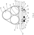
FIG. 4 is a front view of the cable cleat assembly ofFIG. 1 . -
FIG. 1 illustrates thecable cleat assembly 10 of the present invention securing atrefoil cable arrangement 90 to a section of awire basket 100. Thecable cleat assembly 10 is positioned between adjacentlongitudinal wires 104 and adjacenttransverse wires 102 of thewire basket 100. - As illustrated in
FIG. 2 , thecable cleat assembly 10 includes apolymer base plate 12, a preformed round edgestainless steel strap 32,clamp bars fasteners 80. Thepolymer base plate 12 has a top contouredsurface 14 with twoindentations 16 and aflat center member 18 between theindentations 16. Theside edges 20 of thetop contour surface 14 are curved and lead tovertical sides 22. As illustrated inFIGS. 1 and4 , the bottom twocables 92 of thetrefoil cable arrangement 90 are positioned in theindentations 16 in thebase plate 12. Thecurved side edges 20 and theflat center member 18 prevent thecables 92 from moving once thecables 92 are positioned in theindentations 16. Athird cable 92 is positioned on the bottom twocables 92 to form thetrefoil cable arrangement 90. - Each
side 22 of thebase plate 12 is vertical with astrap centering notch 24. Thestrap centering notch 24 maintains thestainless steel strap 32 in position over thetrefoil cable arrangement 90. - The
bottom 26 of thebase plate 12 includes twosemi-circular openings 28. Thesemi-circular openings 28 are sized and spaced to receive adjacentlongitudinal wires 104 of awire basket 100. - The preformed round edge
stainless steel strap 32 includes afirst end member 34, a first verticalstraight side 46, a curved generally U-shapedcenter member 48, a second verticalstraight side 50, and asecond end member 52. Thefirst end member 34 and thesecond end member 52 each include a generally C-shaped portion horizontal portion curved portion straight side 46 and the second verticalstraight side 50, respectively. The generally C-shaped portions center retaining tab holes hole retaining tab - The
first end member 34 and thesecond end member 52 are both designed to receive aclamp bar FIG. 2 , theclamp bars holes center indentation holes 66 in theclamp bar 64 that is installed in thefirst end member 34 are clearance holes extending through theclamp bar 64. Theholes 72 in theclamp bar 70 that is installed in thesecond end member 52 are tappedholes 72. -
FIG. 3 illustrates thefirst end member 34 and thesecond end member 52 with theclamp bars clamp bars end members stainless steel strap 32 by thetabs clamp bars end members tabs indentations clamp bars clamp bars cable cleat assembly 10. - The preformed round edge
stainless steel strap 32 is designed to be placed over thetrefoil cable arrangement 90 and thebase plate 12. As illustrated inFIG. 4 , theend members stainless steel strap 32 are wrapped under thebase plate 12. Twoflange bolts 80 are the fasteners that are used to secure thestainless steel strap 32. However, other types of fasteners may be used to secure thestainless steel strap 32, if desired. Theflange bolts 80 are inserted through theclearance holes 66 in theclamp bar 64 and threaded into the tappedholes 72 in theclamp bar 70. Theflange bolts 80 are tightened with a power tool having a torque limiting clutch and a 12 point socket. During installation of theflange bolts 80, the installer alternates between thebolts 80 to prevent thecable cleat assembly 10 from twisting. Theflange bolts 80 are tightened until thecables 92 are tight. Damage to the cable insulation is avoided by limiting the installation torque to the prescribed torque setting. - The
cable cleat assembly 10 of the present invention provides an easy to assembly cable cleat that maintains a lower overall height on thewire basket 100. Thecable cleat assembly 10 is installed with a tool from only one side. Thebase plate 12 isolates thecables 92 from the clamping hardware and the rounded stainless steel strap edges prevent cable damage without the use of a cushion sleeve. - Furthermore, while the particular preferred embodiments of the present invention have been shown and described, it will be obvious to those skilled in the art that changes and modifications may be made without departing from the teaching of the invention. The matter set forth in the foregoing description and accompanying drawings is offered by way of illustration only and not as limitation.
- The following clauses are disclosed herein:
- 1. A cable cleat assembly for securing cables to a wire basket, the cable cleat assembly comprising:
- a base plate for receiving the cables;
- a stainless steel strap for maintaining the cables on the base plate, wherein the stainless steel strap having a first end member and a second end member, the stainless strap is positioned over the cables on the base plate with the first end member and the second end member wrapped under the base plate;
- clamp bars positioned within the first end member and the second end member; and
- 2. The cable cleat assembly of clause 1, wherein the base plate has a top contoured surface with two indentations and a flat center member positioned between the indentations, whereby the cables are positioned in the indentations.
- 3. The cable cleat assembly of clause 2, wherein the top contoured surface of the base plate has curved side edges that lead to vertical sides of the base plate.
- 4. The cable cleat assembly of clause 1, wherein the base plate has a first vertical side and a second vertical side, each side has a strap centering notch, the strap centering notches adapted to maintain the stainless steel strap in position over the cables.
- 5. The cable cleat assembly of clause 1, wherein the base plate has a bottom with semi-circular openings, the semi-circular openings adapted to receive wires of the wire basket.
- 6. The cable cleat assembly of clause 1, wherein the stainless steel strap further comprising a first vertical straight side extending from the first end member, a curved U-shaped center member, and a second vertical straight side leading to the second end member.
- 7. The cable cleat assembly of clause 1, wherein the first end member and the second end member of the stainless steel strap each includes a C-shaped portion, a horizontal portion, and a curved portion.
- 8. The cable cleat assembly of clause 7, wherein the C-shaped portions of the first end member and the C-shaped portions of the second end member each include a center retaining tab and holes positioned on each side of the center retaining tab.
- 9. The cable cleat assembly of clause 8, wherein the clamp bars include a center indentation with a hole on each side of the center indentation, whereby the holes in the clamp bars align with the holes in the C-shaped portions when the clamp bars are positioned within the first end member and the second end member.
- 10. The cable cleat assembly of clause 9, wherein the center retaining tab of the first end member and the center retaining tab of the second end member cover the center indentations of the clamp bars.
- 11. The cable cleat assembly of clause 1, wherein the clamp bars are a half cylinder with two holes and a center indentation.
- 12. The cable cleat assembly of clause 1, wherein the fasteners extend through clearance holes in the clamp bar positioned in the first end member and the fasteners are threaded into tapped holes in the clamp bar positioned in the second end member.
- 13. The cable cleat assembly of clause 1, wherein the stainless steel strap has rounded edges for preventing cable damage.
- 14. A cable cleat and wire basket assembly for routing cables, the cable cleat and wire basket assembly comprising:
- a wire basket having a plurality of longitudinal wires and a plurality of transverse wires;
- a cable cleat secured to the wire basket, the cable cleat having a base plate with a bottom having semi-circular openings, the semi-circular openings receive longitudinal wires of the wire basket; a stainless steel strap for maintaining the cables on the base plate, wherein the stainless steel strap having a first end member and a second end member, the stainless strap is positioned over the cables on the base plate with the first end member and the second end member wrapped under the base plate;
- clamp bars positioned within the first end member and the second end member; and
- fasteners extending through the clamp bars, the first end member, and the second end member to secure the cable cleat assembly.
- 15. The cable cleat and wire basket assembly of
clause 14, wherein the base plate has a top contoured surface with two indentations, a flat center member positioned between the indentations, and curved side edges that lead to vertical sides of the base plate, whereby the cables are positioned in the indentations. - 16. The cable cleat and wire basket assembly of
clause 14, wherein the base plate has a first vertical side and a second vertical side, each side has a strap centering notch, the strap centering notches adapted to maintain the stainless steel strap in position over the cables. - 17. The cable cleat and wire basket assembly of
clause 14, wherein the stainless steel strap further comprising a first vertical straight side extending from the first end member, a curved U-shaped center member, a second vertical straight side leading to the second end member, and rounded edges for preventing cable damage. - 18. The cable cleat and wire basket assembly of
clause 14, wherein the first end member and the second end member of the stainless steel strap each includes a C-shaped portion, a horizontal portion, and a curved portion, wherein the C-shaped portions of the first end member and the C-shaped portions of the second end member each include a center retaining tab and holes positioned on each side of the center retaining tab, wherein the clamp bars include a center indentation with a hole on each side of the center indentation, whereby the holes in the clamp bars align with the holes in the C-shaped portions when the clamp bars are positioned within the first end member and the second end member. - 19. The cable cleat and wire basket assembly of
clause 14, wherein the clamp bars are a half cylinder with two holes and a center indentation. - 20. The cable cleat and wire basket assembly of
clause 14, wherein the fasteners extend through clearance holes in the clamp bar positioned in the first end member and the fasteners are threaded into tapped holes in the clamp bar positioned in the second end member.
Claims (15)
- A cable cleat assembly for securing cables to a wire basket, the cable cleat assembly comprising:a base plate for receiving the cables;a stainless steel strap for maintaining the cables on the base plate, wherein the stainless steel strap having a first end member and a second end member, the stainless strap is positioned over the cables on the base plate with the first end member and the second end member wrapped under the base plate;clamp bars positioned within the first end member and the second end member; andfasteners extending through the clamp bars, the first end member, and the second end member to secure the cable cleat assembly.
- The cable cleat assembly of claim 1, wherein the base plate has a top contoured surface with two indentations and a flat center member positioned between the indentations, whereby the cables are positioned in the indentations; and optionally
wherein the top contoured surface of the base plate has curved side edges that lead to vertical sides of the base plate. - The cable cleat assembly of claim 1, wherein the base plate has a first vertical side and a second vertical side, each side has a strap centering notch, the strap centering notches adapted to maintain the stainless steel strap in position over the cables.
- The cable cleat assembly of claim 1, wherein the base plate has a bottom with semi-circular openings, the semi-circular openings adapted to receive wires of the wire basket,
or / and optionally,
wherein the stainless steel strap further comprising a first vertical straight side extending from the first end member, a curved U-shaped center member, and a second vertical straight side leading to the second end member. - The cable cleat assembly of claim 1, wherein the first end member and the second end member of the stainless steel strap each includes a C-shaped portion, a horizontal portion, and a curved portion.
- The cable cleat assembly of claim 5, wherein the C-shaped portions of the first end member and the C-shaped portions of the second end member each include a center retaining tab and holes positioned on each side of the center retaining tab.
- The cable cleat assembly of claim 6, wherein the clamp bars include a center indentation with a hole on each side of the center indentation, whereby the holes in the clamp bars align with the holes in the C-shaped portions when the clamp bars are positioned within the first end member and the second end member; and optionally
wherein the center retaining tab of the first end member and the center retaining tab of the second end member cover the center indentations of the clamp bars. - The cable cleat assembly of claim 1, wherein the clamp bars are a half cylinder with two holes and a center indentation.
- The cable cleat assembly of claim 1, wherein the fasteners extend through clearance holes in the clamp bar positioned in the first end member and the fasteners are threaded into tapped holes in the clamp bar positioned in the second end member;
or / and optionally
wherein the stainless steel strap has rounded edges for preventing cable damage. - A cable cleat and wire basket assembly for routing cables, the cable cleat and wire basket assembly comprising:a wire basket having a plurality of longitudinal wires and a plurality of transverse wires;a cable cleat secured to the wire basket, the cable cleat having a base plate with a bottom having semi-circular openings, the semi-circular openings receive longitudinal wires of the wire basket; a stainless steel strap for maintaining the cables on the base plate, wherein the stainless steel strap having a first end member and a second end member, the stainless strap is positioned over the cables on the base plate with the first end member and the second end member wrapped under the base plate;clamp bars positioned within the first end member and the second end member; andfasteners extending through the clamp bars, the first end member, and the second end member to secure the cable cleat assembly.
- The cable cleat and wire basket assembly of claim 10, wherein the base plate has a top contoured surface with two indentations, a flat center member positioned between the indentations, and curved side edges that lead to vertical sides of the base plate, whereby the cables are positioned in the indentations.
- The cable cleat and wire basket assembly of claim 10, wherein the base plate has a first vertical side and a second vertical side, each side has a strap centering notch, the strap centering notches adapted to maintain the stainless steel strap in position over the cables.
- The cable cleat and wire basket assembly of claim 10, wherein the stainless steel strap further comprising a first vertical straight side extending from the first end member, a curved U-shaped center member, a second vertical straight side leading to the second end member, and rounded edges for preventing cable damage.
- The cable cleat and wire basket assembly of claim 10, wherein the first end member and the second end member of the stainless steel strap each includes a C-shaped portion, a horizontal portion, and a curved portion, wherein the C-shaped portions of the first end member and the C-shaped portions of the second end member each include a center retaining tab and holes positioned on each side of the center retaining tab, wherein the clamp bars include a center indentation with a hole on each side of the center indentation, whereby the holes in the clamp bars align with the holes in the C-shaped portions when the clamp bars are positioned within the first end member and the second end member.
- The cable cleat and wire basket assembly of claim 10, wherein the clamp bars are a half cylinder with two holes and a center indentation;
or / and optionally,
wherein the fasteners extend through clearance holes in the clamp bar positioned in the first end member and the fasteners are threaded into tapped holes in the clamp bar positioned in the second end member.
Applications Claiming Priority (2)
| Application Number | Priority Date | Filing Date | Title |
|---|---|---|---|
| US202063058007P | 2020-07-29 | 2020-07-29 | |
| US17/377,825 US11677220B2 (en) | 2020-07-29 | 2021-07-16 | Low profile cable cleat assembly |
Publications (2)
| Publication Number | Publication Date |
|---|---|
| EP3945648A1 true EP3945648A1 (en) | 2022-02-02 |
| EP3945648B1 EP3945648B1 (en) | 2026-01-28 |
Family
ID=77021243
Family Applications (1)
| Application Number | Title | Priority Date | Filing Date |
|---|---|---|---|
| EP21187149.6A Active EP3945648B1 (en) | 2020-07-29 | 2021-07-22 | Low profile cable cleat assembly |
Country Status (2)
| Country | Link |
|---|---|
| US (1) | US11677220B2 (en) |
| EP (1) | EP3945648B1 (en) |
Cited By (1)
| Publication number | Priority date | Publication date | Assignee | Title |
|---|---|---|---|---|
| CN116105097A (en) * | 2023-02-28 | 2023-05-12 | 中国五冶集团有限公司 | Lamp strip screen fixing device |
Families Citing this family (4)
| Publication number | Priority date | Publication date | Assignee | Title |
|---|---|---|---|---|
| USD1061199S1 (en) * | 2022-10-02 | 2025-02-11 | Fiber Reaper, LLC | Cable clamp |
| US12338923B2 (en) | 2023-04-14 | 2025-06-24 | Joseph Rutkowski | Data cable retaining post |
| US20250164037A1 (en) * | 2023-11-20 | 2025-05-22 | Rectorseal, Llc | Hanger assembly for duct |
| US20250251059A1 (en) * | 2024-02-07 | 2025-08-07 | Tom Nepola | High vibration clamp assembly |
Citations (4)
| Publication number | Priority date | Publication date | Assignee | Title |
|---|---|---|---|---|
| US4365393A (en) * | 1981-05-11 | 1982-12-28 | Mueller Co. | Single and multiple section pipe repair clamps |
| EP1195531B1 (en) * | 2000-10-04 | 2003-07-23 | Rasmussen GmbH | Clamp band |
| GB2473492A (en) * | 2009-09-15 | 2011-03-16 | Ellis Patents Ltd | Intermediate fixing for a cable basket tray |
| WO2019236445A1 (en) * | 2018-06-08 | 2019-12-12 | Panduit Corp. | Cable cleat assembly |
Family Cites Families (27)
| Publication number | Priority date | Publication date | Assignee | Title |
|---|---|---|---|---|
| US508822A (en) * | 1893-11-14 | Plumber s tack | ||
| GB722084A (en) | 1952-11-29 | 1955-01-19 | Taylor And Osborne Ltd | Improvements relating to cleats or clamps for use in supporting cables, conduits andthe like |
| US2828525A (en) * | 1954-11-19 | 1958-04-01 | Jack & Heintz Inc | Clamping band |
| US2939664A (en) * | 1955-08-29 | 1960-06-07 | William O Wesseler | Cable hanger |
| US4179774A (en) * | 1978-06-22 | 1979-12-25 | Cable Supports Limited | Cable clamps |
| AU540604B2 (en) * | 1980-08-13 | 1984-11-29 | Bicc General Uk Cables Limited | Pipe or cable securing device |
| US4440374A (en) | 1981-04-21 | 1984-04-03 | Illinois Tool Works Inc. | Integrally formed resilient clip and extension |
| US5221065A (en) * | 1992-04-16 | 1993-06-22 | Caterpillar Inc. | Mounting bracket for restraint of elongate articles |
| FR2797528B1 (en) * | 1999-08-10 | 2001-10-26 | Metal Deploye Sa | DEVICE FOR GUIDING AT LEAST ONE FLEXIBLE LONG ELEMENT, SUCH AS CABLE OR THE LIKE, WITH SUBSTANTIALLY CLOSED CONTOUR |
| US6634607B2 (en) * | 2001-09-14 | 2003-10-21 | Donaldson Company, Inc. | Pipe clamp |
| US20030198520A1 (en) * | 2002-04-22 | 2003-10-23 | Evans Daniel D. | Conduit retainer apparatus |
| US7654492B2 (en) | 2004-05-03 | 2010-02-02 | The Boeing Company | Wire bundle support system |
| US7130521B2 (en) * | 2004-08-20 | 2006-10-31 | Gs Metals Corp. | Cable guide |
| US20090200435A1 (en) * | 2005-02-14 | 2009-08-13 | Duggan Daniel C | Hanger rod stiffening clip |
| JP4864503B2 (en) | 2006-03-23 | 2012-02-01 | 株式会社栗本鐵工所 | Power cable cleats |
| FR2912003B1 (en) * | 2007-01-31 | 2009-04-17 | Icm Group | FIXING DEVICE FOR WIRE ROAD PATH |
| KR101088511B1 (en) | 2009-09-29 | 2011-11-30 | (주)대하인터네셔널 | Cable creat |
| US8424814B2 (en) | 2010-05-19 | 2013-04-23 | Panduit Corp. | Cable tray cable routing system |
| KR101303094B1 (en) | 2012-06-01 | 2013-09-06 | 삼성파워텍주식회사 | Cable cleat assembly |
| KR101339144B1 (en) | 2013-04-15 | 2013-12-09 | 주식회사 디피아이 | Cable cleats |
| KR101582285B1 (en) | 2015-04-30 | 2016-01-05 | (주)건일종합기술 | Cable Fastener for Underground Electrical Conduit of Appartment House |
| GB201516237D0 (en) | 2015-09-14 | 2015-10-28 | Ellis Patents Holdings Ltd | A clamp |
| KR101848847B1 (en) | 2017-09-26 | 2018-04-16 | 주식회사 토문엔지니어링건축사사무소 | Electric wire support device |
| KR102077540B1 (en) | 2017-12-21 | 2020-02-14 | 대한전선 주식회사 | Cable cleat |
| EP3557710A1 (en) | 2018-04-20 | 2019-10-23 | CMP Products Limited | Appartus for retaining electrical cables |
| CN108697026B (en) | 2018-05-29 | 2020-12-22 | 广西电网有限责任公司玉林供电局 | A network cabinet tray |
| KR102009659B1 (en) | 2019-03-26 | 2019-08-13 | 주식회사 다인그룹엔지니어링건축사사무소 | Leakage and short circuit monitoring apparatus of apartment house electricity |
-
2021
- 2021-07-16 US US17/377,825 patent/US11677220B2/en active Active
- 2021-07-22 EP EP21187149.6A patent/EP3945648B1/en active Active
Patent Citations (4)
| Publication number | Priority date | Publication date | Assignee | Title |
|---|---|---|---|---|
| US4365393A (en) * | 1981-05-11 | 1982-12-28 | Mueller Co. | Single and multiple section pipe repair clamps |
| EP1195531B1 (en) * | 2000-10-04 | 2003-07-23 | Rasmussen GmbH | Clamp band |
| GB2473492A (en) * | 2009-09-15 | 2011-03-16 | Ellis Patents Ltd | Intermediate fixing for a cable basket tray |
| WO2019236445A1 (en) * | 2018-06-08 | 2019-12-12 | Panduit Corp. | Cable cleat assembly |
Cited By (1)
| Publication number | Priority date | Publication date | Assignee | Title |
|---|---|---|---|---|
| CN116105097A (en) * | 2023-02-28 | 2023-05-12 | 中国五冶集团有限公司 | Lamp strip screen fixing device |
Also Published As
| Publication number | Publication date |
|---|---|
| US11677220B2 (en) | 2023-06-13 |
| US20220037866A1 (en) | 2022-02-03 |
| EP3945648B1 (en) | 2026-01-28 |
Similar Documents
| Publication | Publication Date | Title |
|---|---|---|
| US11677220B2 (en) | Low profile cable cleat assembly | |
| US10910805B2 (en) | Adapter for mounting cable hangers | |
| EP3827492B1 (en) | Device and method for guiding and protecting at least one electric cable in a solar panel mounting system | |
| US5393930A (en) | Self-anchoring poke-through wiring device | |
| US10240393B2 (en) | Thermal expansion and contraction system | |
| US5118057A (en) | Cable fitting | |
| US11300230B2 (en) | Adapter for mounting cable hangers | |
| CN102640356A (en) | Elastic connecting terminal | |
| EP3706272B1 (en) | Bracket for cable management | |
| US10673219B2 (en) | Electrical box cable connector | |
| EP4148923A1 (en) | Dual tongue strap cleat bracket | |
| US20240413787A1 (en) | Cable management system | |
| JP2004263859A (en) | Button type fixing device | |
| US6559387B1 (en) | Universal ground clamp with S-shaped second strap | |
| US7897871B1 (en) | Junction box with integrated connectors for electrical wiring | |
| US20220302690A1 (en) | Electrical box cable connector | |
| EP1746697B1 (en) | Securing element for securing a box to a wire cable tray | |
| WO2008154328A2 (en) | Sheet metal ground conductor clamp | |
| US11817687B2 (en) | Cable tray clips and methods for using the same | |
| US20200094086A1 (en) | Safety Cable Routing System | |
| KR20220116930A (en) | Rack for supporting low voltage cabel or neutral line | |
| RU2740939C1 (en) | Supporting clamp (versions) | |
| CN221150817U (en) | Cable fixing device | |
| EP0310286A1 (en) | Cable cleat | |
| WO2026087895A1 (en) | Cable cleat |
Legal Events
| Date | Code | Title | Description |
|---|---|---|---|
| PUAI | Public reference made under article 153(3) epc to a published international application that has entered the european phase |
Free format text: ORIGINAL CODE: 0009012 |
|
| STAA | Information on the status of an ep patent application or granted ep patent |
Free format text: STATUS: THE APPLICATION HAS BEEN PUBLISHED |
|
| AK | Designated contracting states |
Kind code of ref document: A1 Designated state(s): AL AT BE BG CH CY CZ DE DK EE ES FI FR GB GR HR HU IE IS IT LI LT LU LV MC MK MT NL NO PL PT RO RS SE SI SK SM TR |
|
| STAA | Information on the status of an ep patent application or granted ep patent |
Free format text: STATUS: REQUEST FOR EXAMINATION WAS MADE |
|
| 17P | Request for examination filed |
Effective date: 20220727 |
|
| RBV | Designated contracting states (corrected) |
Designated state(s): AL AT BE BG CH CY CZ DE DK EE ES FI FR GB GR HR HU IE IS IT LI LT LU LV MC MK MT NL NO PL PT RO RS SE SI SK SM TR |
|
| STAA | Information on the status of an ep patent application or granted ep patent |
Free format text: STATUS: EXAMINATION IS IN PROGRESS |
|
| 17Q | First examination report despatched |
Effective date: 20240313 |
|
| GRAP | Despatch of communication of intention to grant a patent |
Free format text: ORIGINAL CODE: EPIDOSNIGR1 |
|
| STAA | Information on the status of an ep patent application or granted ep patent |
Free format text: STATUS: GRANT OF PATENT IS INTENDED |
|
| RIC1 | Information provided on ipc code assigned before grant |
Ipc: H02G 3/32 20060101AFI20250929BHEP Ipc: H02G 3/30 20060101ALI20250929BHEP Ipc: H02G 3/04 20060101ALN20250929BHEP |
|
| INTG | Intention to grant announced |
Effective date: 20251013 |
|
| GRAS | Grant fee paid |
Free format text: ORIGINAL CODE: EPIDOSNIGR3 |
|
| GRAA | (expected) grant |
Free format text: ORIGINAL CODE: 0009210 |
|
| STAA | Information on the status of an ep patent application or granted ep patent |
Free format text: STATUS: THE PATENT HAS BEEN GRANTED |
|
| AK | Designated contracting states |
Kind code of ref document: B1 Designated state(s): AL AT BE BG CH CY CZ DE DK EE ES FI FR GB GR HR HU IE IS IT LI LT LU LV MC MK MT NL NO PL PT RO RS SE SI SK SM TR |
|
| REG | Reference to a national code |
Ref country code: CH Ref legal event code: F10 Free format text: ST27 STATUS EVENT CODE: U-0-0-F10-F00 (AS PROVIDED BY THE NATIONAL OFFICE) Effective date: 20260128 Ref country code: GB Ref legal event code: FG4D |
|
| REG | Reference to a national code |
Ref country code: DE Ref legal event code: R096 Ref document number: 602021046645 Country of ref document: DE |
|
| REG | Reference to a national code |
Ref country code: IE Ref legal event code: FG4D |