EP3945396B1 - Erkennung von konflikten entlang einer route eines roboters - Google Patents
Erkennung von konflikten entlang einer route eines roboters Download PDFInfo
- Publication number
- EP3945396B1 EP3945396B1 EP21187642.0A EP21187642A EP3945396B1 EP 3945396 B1 EP3945396 B1 EP 3945396B1 EP 21187642 A EP21187642 A EP 21187642A EP 3945396 B1 EP3945396 B1 EP 3945396B1
- Authority
- EP
- European Patent Office
- Prior art keywords
- robot
- data
- nearby moving
- moving object
- velocity
- Prior art date
- Legal status (The legal status is an assumption and is not a legal conclusion. Google has not performed a legal analysis and makes no representation as to the accuracy of the status listed.)
- Active
Links
Images




Classifications
-
- G—PHYSICS
- G05—CONTROLLING; REGULATING
- G05D—SYSTEMS FOR CONTROLLING OR REGULATING NON-ELECTRIC VARIABLES
- G05D1/00—Control of position, course, altitude or attitude of land, water, air or space vehicles, e.g. using automatic pilots
- G05D1/10—Simultaneous control of position or course in three dimensions
- G05D1/101—Simultaneous control of position or course in three dimensions specially adapted for aircraft
- G05D1/106—Change initiated in response to external conditions, e.g. avoidance of elevated terrain or of no-fly zones
-
- G—PHYSICS
- G05—CONTROLLING; REGULATING
- G05D—SYSTEMS FOR CONTROLLING OR REGULATING NON-ELECTRIC VARIABLES
- G05D1/00—Control of position, course, altitude or attitude of land, water, air or space vehicles, e.g. using automatic pilots
- G05D1/60—Intended control result
- G05D1/617—Safety or protection, e.g. defining protection zones around obstacles or avoiding hazards
- G05D1/622—Obstacle avoidance
- G05D1/637—Obstacle avoidance using safety zones of adjustable size or shape
-
- G—PHYSICS
- G08—SIGNALLING
- G08G—TRAFFIC CONTROL SYSTEMS
- G08G5/00—Traffic control systems for aircraft
- G08G5/80—Anti-collision systems
-
- G—PHYSICS
- G05—CONTROLLING; REGULATING
- G05D—SYSTEMS FOR CONTROLLING OR REGULATING NON-ELECTRIC VARIABLES
- G05D1/00—Control of position, course, altitude or attitude of land, water, air or space vehicles, e.g. using automatic pilots
- G05D1/0088—Control of position, course, altitude or attitude of land, water, air or space vehicles, e.g. using automatic pilots characterized by the autonomous decision making process, e.g. artificial intelligence, predefined behaviours
-
- G—PHYSICS
- G05—CONTROLLING; REGULATING
- G05D—SYSTEMS FOR CONTROLLING OR REGULATING NON-ELECTRIC VARIABLES
- G05D1/00—Control of position, course, altitude or attitude of land, water, air or space vehicles, e.g. using automatic pilots
- G05D1/02—Control of position or course in two dimensions
- G05D1/021—Control of position or course in two dimensions specially adapted to land vehicles
- G05D1/0212—Control of position or course in two dimensions specially adapted to land vehicles with means for defining a desired trajectory
- G05D1/0214—Control of position or course in two dimensions specially adapted to land vehicles with means for defining a desired trajectory in accordance with safety or protection criteria, e.g. avoiding hazardous areas
-
- G—PHYSICS
- G08—SIGNALLING
- G08G—TRAFFIC CONTROL SYSTEMS
- G08G5/00—Traffic control systems for aircraft
- G08G5/50—Navigation or guidance aids
- G08G5/53—Navigation or guidance aids for cruising
-
- G—PHYSICS
- G08—SIGNALLING
- G08G—TRAFFIC CONTROL SYSTEMS
- G08G5/00—Traffic control systems for aircraft
- G08G5/50—Navigation or guidance aids
- G08G5/55—Navigation or guidance aids for a single aircraft
-
- G—PHYSICS
- G08—SIGNALLING
- G08G—TRAFFIC CONTROL SYSTEMS
- G08G5/00—Traffic control systems for aircraft
- G08G5/50—Navigation or guidance aids
- G08G5/57—Navigation or guidance aids for unmanned aircraft
-
- G—PHYSICS
- G05—CONTROLLING; REGULATING
- G05D—SYSTEMS FOR CONTROLLING OR REGULATING NON-ELECTRIC VARIABLES
- G05D2109/00—Types of controlled vehicles
- G05D2109/20—Aircraft, e.g. drones
- G05D2109/22—Aircraft, e.g. drones with fixed wings
- G05D2109/23—Vertical take-off and landing [VTOL] aircraft; Short take-off and landing [STOL, STOVL] aircraft
Definitions
- the present disclosure relates generally to robotics and, in particular, to one or more of the design, construction, operation or use of autonomous robots such as autonomous or semi-autonomous vehicles.
- unmanned vehicles include unmanned ground vehicles (UGVs), unmanned aerial vehicles (UAVs), unmanned surface vehicles (USVs), unmanned underwater vehicles (UUVs), unmanned spacecraft and the like.
- UUVs unmanned ground vehicles
- UAVs unmanned aerial vehicles
- USVs unmanned surface vehicles
- UUVs unmanned underwater vehicles
- robot operation includes automatic control of a given robot to support remote human control.
- optimization systems and associated methods to determine how, for a given robot or set of robots, tasks should be ordered and/or allocated.
- robot operation is automatic, real-time or near real-time data processing, and exploitation in support of automatic route planning, mission execution and other activities.
- existing autonomy systems are typically configured to address only one example of these activities, thereby focusing its design of the underling autonomy algorithms and software architecture on a narrow mission set. This limits the extensibility of existing autonomy systems, as they are not well-equipped to support the addition of new modules to the autonomy system. Furthermore, existing autonomy systems may or may not be structured for rapid adaptation to new platforms through parameterization.
- US 2014/0249738 in accordance with its abstract, states systems and methods are operable to maintain a proscribed self separation distance between an unmanned aircraft system (UAS) and an object.
- UAS unmanned aircraft system
- consecutive intruder aircraft locations relative to corresponding locations of a self aircraft are determined, wherein the determining is based on current velocities of the intruder aircraft and the self aircraft, and wherein the determining is based on current flight paths of the intruder aircraft and the self aircraft.
- At least one evasive maneuver for the self aircraft is computed using a processing system based on the determined consecutive intruder aircraft locations relative to the corresponding locations of the self aircraft.
- US 2019/0088146 in accordance with its abstract, states a method and a device for avoiding an object detect its approach to an aircraft. After detecting an object in the vicinity of an aircraft and detecting its approach, a first track for the object and a second track for the aircraft are estimated from successive first states for the object and successive second states for the aircraft. Thereafter, a minimum distance (d m ) between the first track and the second track is estimated and a warning is triggered as soon as the minimum distance is less than a first threshold so as to warn a crew of the aircraft of a risk of collision. Finally, if the minimum distance is less than a second threshold, an avoidance maneuver is performed automatically by the aircraft in order to move away from the first track, and thereby avoid any risk of collision with the object.
- FGA showed a 90% of reduction in computational time for the same obstacle avoidance scenario.
- the UAS is able to avoid static and dynamic obstacles while still being able to recover its original trajectory after successful collision avoidance.
- Simulations for different mission scenarios show that this method is much more efficient at avoiding multiple obstacles than previous methods.
- Algorithm effectiveness validation is provided with Monte Carlo simulations and flight missions in an aircraft simulator. FGA was also tested on a fixed-wing aircraft with successful results. Because this algorithm does not have specific requirements on the sensor data types it can be applied to cooperative and non-cooperative intruders.
- an anti-collision device of an aircraft comprising a plurality of sensors, the plurality of sensors comprising at least two separate sensors, each sensor being configured to respectively deliver its own set of captured data as a function of the proximity of at least one obstruction
- the anti-collision device comprising: at least one data homogenization module configured to transform at least one set of captured data in a corresponding set of unmarked data, each set of unmarked data respectively associated with at least one sensor being made up of a plurality of identical data types from one set of unmarked data to another, and a data processing module configured to generate, from said sets of unmarked data, at least one piece of information representative of the presence or absence of obstruction(s).
- a method optionally a computer-implemented method, of detecting conflict along a route for a robot to travel, the method comprising: receiving first data that indicate a first position and a first velocity of one or more nearby moving objects, or from which the first position and the first velocity of the one or more nearby moving objects are determined.
- the first data comprise sensor data acquired by a variety of different sensors, and are filtered and/or correlated from multiple observations of the one or more nearby moving objects.
- the method comprises: generating a vector projection of the nearby moving object from the first position and using the first velocity of the nearby moving object, wherein the vector projection corresponds to a predicted trajectory of the nearby moving object; generating a trajectory of the robot on the route for the robot to travel, wherein the trajectory is generated from second data that indicate a second position and a second velocity of the robot; performing a comparison of the nearby moving object and the robot on respectively the predicted trajectory of the nearby moving object and the trajectory of the robot, wherein the comparison is performed to detect a conflict when the nearby moving object is within a clear region that includes the robot, and a time to closest point of approach between nearby moving object and the robot is less than a time threshold value; and, when the conflict is detected, outputting an indication of the conflict for use in at least one of guidance, navigation or control of the robot to avoid the conflict.
- Performing the comparison includes performing a stepwise comparison that includes a plurality of timesteps, and the clear region is dynamic in size to account for sensor uncertainty in one or more sensors of the variety of different sensors and in that the clear region is different in size for a later one of the plurality of timesteps relative to an earlier one of the plurality of timesteps to account for uncertainty in the first data.
- a method of detecting conflict along a route for a robot to travel comprising receiving first data that indicates a first position and a first velocity of one or more nearby moving objects, or from which the first position and the first velocity of the one or more nearby moving objects are determined; and for each nearby moving object of the one or more nearby moving objects, generating a vector projection of the nearby moving object from the first position and using the first velocity of the nearby moving object, the vector projection corresponding to a predicted trajectory of the nearby moving object; generating a trajectory of the robot on the route for the robot to travel, and from second data that indicates a second position and a second velocity of the robot; performing a comparison of the nearby moving object and the robot on respectively the predicted trajectory of the nearby moving object and the trajectory of the robot, the comparison performed to detect a conflict when the nearby moving object is within a clear region that includes the robot, and a time to closest point of approach between nearby moving object and the robot is less than a time threshold value; and when the conflict is detected, outputting an indication of the conflict for use
- the route for the robot to travel may be described by at least one of a route command, a flight plan or a mission route, and generating the trajectory of the robot may include generating the trajectory of the robot using the at least one of the route command, the flight plan or the mission route.
- Receiving the first data may comprise receiving the first data from a sensor operatively in communication with the robot and having a first data format, or data-linked from the nearby moving object and having a second data format; and transforming the first data from the first data format or the second data format to a third data format from which the vector projection and thereby the predicted trajectory of the nearby moving object is generated.
- the method may further comprise applying the first data to a filter that passes the first data for generating the vector projection only when the first position of the nearby moving object is within a given region of interest that includes the robot at the second position.
- the first data may further indicate a time and an accuracy of the first data
- the method may further comprise applying the first data to a filter that passes the first data for generating the vector projection only when the time is within a time threshold of current time, and the accuracy is within an accuracy threshold.
- the first position and the first velocity may be observations of position and velocity
- receiving the first data may comprise receiving data from multiple sources including respective observations of position and velocity of the one or more nearby moving objects; correlating the respective observations of position and velocity; and based on the respective observations having at least a threshold degree of correlation that indicates the respective observations are for the nearby moving object, selecting an observation of position and velocity from the respective observations as the respectively first position and the first velocity of the nearby moving object.
- the first data may further indicate accuracies of the respective observations of position and velocity, and selecting the observation may include selecting the observation that is most accurate as indicated by a highest one of the accuracies.
- the one or more nearby moving objects may be a plurality of nearby moving objects, and wherein the method may further comprise applying the first data to a filter that passes the first data for generating the vector projection for only a given number of the plurality of nearby moving objects, and the vector projection and thereby the predicted trajectory of the nearby moving object is generated for each nearby moving object.
- Performing the comparison includes performing a stepwise comparison that includes a plurality of timesteps, and the clear region is dynamic in size in that the clear region is different in size for a later one of the plurality of timesteps relative to an earlier one of the plurality of timesteps.
- the method may further comprise determining at least one maneuver to avoid the conflict; and causing the robot to execute the at least one maneuver.
- an apparatus for detecting conflict along a route for a robot to travel comprising a memory having computer-readable program code stored therein; and processing circuitry configured to access the memory, and execute the computer-readable program code to cause the apparatus to perform any of the methods described above.
- a computer-readable storage medium for detecting conflict along a route for a robot to travel, the computer-readable storage medium being non-transitory and having computer-readable program code stored therein that, in response to execution by processing circuitry, causes an apparatus to perform any of the methods described above.
- a feature may be described as being above another feature (unless specified otherwise or clear from context) may instead be below, and vice versa; and similarly, features described as being to the left of another feature else may instead be to the right, and vice versa.
- the "or" of a set of operands is the “inclusive or” and thereby true if and only if one or more of the operands is true, as opposed to the "exclusive or” which is false when all of the operands are true.
- “[A] or [B]” is true if [A] is true, or if [B] is true, or if both [A] and [B] are true.
- a robot is a machine designed and configurable to execute maneuvers in its environment.
- the robot may be manned or unmanned.
- the robot may be fully human-controlled, or the robot may be semi-autonomous or autonomous in which at least some of the maneuvers are executed independent of or with minimal human intervention.
- the robot is operable in various modes with various amounts of human control.
- a robot designed and configurable to fly may at times be referred to as an aerial robot.
- a robot designed and configurable to operate with at least some level of autonomy may at times be referred to as an autonomous robot, or an autonomous aerial robot in the case of an autonomous robot that is also designed and configurable to fly.
- suitable robots include aerobots, androids, automatons, autonomous vehicles, explosive ordnance disposal robots, hexapods, industrial robots, insect robots, microbots, nanobots, military robots, mobile robots, rovers, service robots, surgical robots, walking robots and the like.
- unmanned vehicles including unmanned ground vehicles (UGVs), unmanned aerial vehicles (UAVs), unmanned surface vehicles (USVs), unmanned underwater vehicles (UUVs), unmanned spacecraft and the like.
- UUVs unmanned ground vehicles
- UAVs unmanned aerial vehicles
- USVs unmanned surface vehicles
- UUVs unmanned underwater vehicles
- unmanned spacecraft and the like.
- UUVs unmanned ground vehicles
- UAVs unmanned aerial vehicles
- UUVs unmanned surface vehicles
- UUVs unmanned underwater vehicles
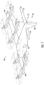
- FIG. 1 illustrates one type of robot, namely, a UAV 100, that may benefit from examples of the present disclosure.
- the UAV may include a fuselage 102, wings 104 extending from opposing sides of the UAV in a mid-section of the fuselage, and an empennage or tail assembly 106 at a rear end of the fuselage.
- the tail assembly includes a vertical stabilizer 108 and two horizontal stabilizers 110 extending from opposing sides of the UAV.
- Rotors 112 and 114 are mounted to respectively the wings and the end of the tail assembly for lifting and propelling the UAV during flight.
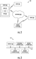
- FIG. 2 illustrates a system 200 according to some examples of the present disclosure.
- the system may include any of a number of different subsystems (each an individual system) for performing one or more functions or operations.
- the system includes a control station 202 and one or more robots 204 (e.g., one or more UAVs 100).
- the control station provides facilities for communication with or control of the one or more robots, such as by wired or wireless data links directly or across one or more networks 206.
- the control station may be a ground station, and not in all cases control the robots.
- the control station may be configured to monitor the robots.
- the control station may initiate mission, but the control station may not control the robots to maneuver. At times, then, the control station may enable or provide a distributed network/server of software functions.
- the robot 204 includes a robot management system (RMS) 208 and a mission management system (MMS) 210.
- the RMS is a robot-specific subsystem configured to manage subsystems and other components of the robot. These subsystems and other components include, for example, maneuver controls, landing gear, onboard environmental systems, electrical, pneumatic and hydraulic systems, communications systems, navigation systems and other subsystems and components for controlling operation and maneuvering of the robot.
- the RMS is configured to accept maneuver commands such as waypoints and/or steering commands, and control the robot to follow those maneuver commands.
- the RMS is at times referred to as a vehicle management system (VMS).
- VMS vehicle management system
- the MMS 210 is a subsystem configured to manage missions of the robot 204.
- a mission is a deployment of the robot (one or more robots) to achieve one or more mission objectives.
- a mission may be decomposed into maneuvers of the robot with optional sensor and/or effector scheduling, and the MMS may execute tasks to manage the robot to execute maneuvers with specific parameters and capabilities.
- the MMS 210 includes subsystems to process sensor data to situational awareness, plan tasks for the robot 204 (or multiple robots), coordinate with teams to assign tasks, execute assigned tasks.
- the MMS is also configured to interface with the RMS 208, and in some examples the control station 202. Although the MMS is shown on the robot 204, the MMS may instead be at the control station; or in some examples, the MMS may be distributed between the robot and the control station.
- the MMS 210 provides a complete, end-to-end autonomy architecture with open system architecture standards and parameterized to allow rapid extension and reapplication to a variety of robots.
- the flexibility of the MMS enables an operator to code it once, but to apply it anywhere.
- the MMS may therefore be applied to virtually any robot that applies, or benefits from, autonomy.
- the MMS may include an adaptable autonomy architecture that is applicable to a variety of robots, including those identified above.
- a benefit of the MMS is therefore not only in the specific contents, but also in the specific details of the architecture, its subroutines, and in the interfaces between those subroutines and other systems/devices that support rapid extensibility and adaptability of the MMS to a variety of domains.
- FIG. 3 more particularly illustrates the MMS 210 according to some examples of the present disclosure.
- the MMS may include any of a number of different subsystems (each an individual system) for performing one or more functions or operations.
- the MMS includes an interface subsystem 302, a situational awareness subsystem 304, a mission planning subsystem 306, a mission coordination subsystem 308, and a mission execution subsystem 310.
- the subsystems of the MMS may be on the robot 204, at the control station 202, or distributed between the robot and the control station.
- the subsystems may be configured to communicate with one another directly, over a communication bus 312, or across the network(s) 206 in examples in which the MMS is distributed between the robot and the control station.
- the subsystems enable the MMS 210 of the robot 204 to interface with the system 200, perform situational awareness, plan a mission including a plurality of tasks, coordinate the plurality of tasks and thereby the mission with other robots 204, and execute the mission.
- the MMS may use the interface subsystem 302 to interface with various sensors onboard the robot, the RMS 208, the control station 202 and/or other robots.
- the MMS may use the situational awareness subsystem 304 to acquire sensor data and maintain an awareness of the state of the environment in which the robot is operating.
- the MMS may use the mission planning subsystem 306 to plan a mission including or associated with a plurality of tasks, and which may incorporate rules of engagement, tactics and other constraints on operations.
- the MMS may likewise use the mission planning subsystem to dynamically replan a mission in which changes to the mission are made in real-time or near real-time as the mission is executed.
- the MMS may use the mission coordination subsystem 308 to coordinate the plurality of tasks of the mission with other robots and users, where agreed-upon tasks may then be executed by the MMS using the mission execution subsystem 310.
- the MMS 210 is also configured to implement software functionality or functionalities (at times referred to as services) during a mission to provide the robot 204 with conflict detection and avoidance capabilities.
- the robot may take a path, and this path may be described by a series of waypoints that define a route the robot will travel.
- the robot travels with a velocity (speed and direction of motion), and the series of waypoints and velocities at that define the route with respect to time defines a trajectory of the robot (at times referred to as a track of the robot).
- the conflict detection and avoidance capabilities enable the robot to detect and avoid conflicts along its route of travel.
- FIG. 4 illustrates a scenario 400 in which the robot 204 is executing a mission in which the robot is to travel on a route 402 in an environment in which one or more moving objects 404 are nearby the robot.
- these moving objects are other robots that may be of the same type or different types than the robot.
- suitable moving objects include non-robot vehicles such as any of a number of different types of ground vehicles, watercraft, aircraft, spacecraft or the like.
- FIG. 5 is a diagram of services 500 that may be implemented by the MMS 210 for conflict detection and avoidance with respect to nearby moving objects 404, according to some examples.
- the services may include a sensor interface 502 service, track management 504 service and conflict detection 506 service.
- the sensor interface service may be implemented by the interface subsystem 302 of the MMS.
- the track management service and the conflict detection service may be implemented by respective ones of the situational awareness subsystem 304 and the mission execution subsystem 310 of the MMS.
- the sensor interface 502 service is configured to receive first data that indicates a first position 406 and a first velocity 408 of the nearby moving object(s) 404, or the first position and the first velocity are determined from the first data.
- the first data may include sensor data from any of a number of different sensors including those employing technologies such as acoustics, radio, optics and the like. More particular examples of suitable sensors include those employing radar, lidar, infrared sensors, cameras and the like.
- ADS-B automatic, dependent surveillance-broadcast
- the first data is from a sensor operatively in communication with the robot 204 and has a first data format (e.g., radar), or data-linked from the nearby moving object(s) 404 and having a second data format (e.g., ADS-B).
- a first data format e.g., radar
- ADS-B second data format
- a number of sensors such as those employing radar, lidar, infrared sensors, cameras and the like generate images from reflected electromagnetic waves (e.g., radio, infrared radiation, visible light) or mechanical waves (e.g., sound waves). These images may be used to detect the presence and position of a nearby moving object 404 ; and in some examples, the nearby moving object may also be identified. The images may also be used to track the nearby moving object using multiple sequential detections over time, which may in turn be used to determine its velocity.
- reflected electromagnetic waves e.g., radio, infrared radiation, visible light
- mechanical waves e.g., sound waves
- ADS-B is a surveillance technology for tracking aircraft that uses satellite-based navigation technology and a broadcast communications data-link (ADS-B unit).
- a nearby moving object 404 that is an ADS-B capable aircraft may use a satellite-based navigation receiver to derive its precise position from satellites, and combine that position with state information such as velocity, altitude and flight number.
- the nearby moving object / aircraft may then broadcast this information via an ADS-B signal to other ADS-B capable systems, which may include the robot 204.
- the track management 504 service and the conflict detection 506 service are configured to perform a number of operations for each nearby moving object 404 of the nearby moving object(s).
- the track management service includes one or more sub-services (each an individual service) such as a transform 508 service, a filter 510 service, a correlate 512 service and/or a track generation 514 service.
- the track generation service is configured to generate a vector projection of the first velocity 408 of the nearby moving object from the first position 406 of the nearby moving object. This vector projection corresponds to a predicted trajectory 410 of the nearby moving object.
- the track generation 514 service of the track management 504 service is also configured to generate a trajectory 412 of the robot 204 on the route 402, from second data that indicates a second position 414 and a second velocity 416 of the robot.
- the second data may include state data that describes position and velocity of the robot, and which in some examples may be received from the RMS 208.
- the route for the robot is described by a route command, a flight plan (for an aerial robot) and/or a mission route; and in some of these examples, the trajectory of the robot is generated using the route command, the flight plan and/or the mission route.
- the route in some examples is a planned route of the robot.
- the transform 508 service is configured to transform the first data to a third data format.
- the filter 510 service is configured to apply the first data to one or more filters before the vector projection for the predicted trajectory 410 is generated.
- the filter service is configured to apply the first data to a filter that passes the first data for generation of the vector projection only when the first position 406 of the nearby moving object 404 is within a given region of interest 418 that includes the robot 204 at the second position 414.
- the first data further indicates a time and an accuracy of the first data
- the filter service is configured to apply the first data to a filter that passes the first data for generation of the vector projection only when the time is within a time threshold of current time, and the accuracy is within an accuracy threshold.
- the filter 510 service is configured to apply the first data to a filter that passes the first data for generation of the vector projection for only a given number of the plurality of nearby moving objects.
- the first position 406 and the first velocity 408 of the nearby moving object 404 are observations of position and velocity
- the first data includes data from multiple sources including respective observations of position and velocity of the nearby moving object(s).
- the correlate 512 service is configured to correlate the respective observations of position and velocity; and in some examples, the respective observations have at least a threshold degree of correlation that indicates the respective observations are for the nearby moving object (e.g., a single nearby moving object that is the nearby moving object). Based on this threshold degree of correlation, the correlate service is configured to select an observation of position and velocity from the respective observations as the respectively first position and the first velocity of the nearby moving object.
- the first data further indicates accuracies of the respective observations of position and velocity
- the correlate service is configured to select the observation that is most accurate as indicated by a highest one of the accuracies.
- the conflict detection 506 service of the services 500 that may be implemented by the MMS 210 is configured to perform a comparison of the nearby moving object 404 and the robot 204 on respectively the predicted trajectory 410 of the nearby moving object and the trajectory 412 of the robot.
- the comparison is performed to detect a conflict when the nearby moving object is within a clear region 422 that includes the robot, and a time to closest point of approach between nearby moving object and the robot is less than a time threshold value.
- conflict detection 506 service is configured to perform a stepwise comparison.
- the conflict detection service is configured to determine updated positions 406A, 414A and updated velocities 408A, 416A of the nearby moving object and the robot on respectively the predicted trajectory of the nearby moving object and the trajectory of the robot.
- the conflict detection 506 service is configured to determine if the nearby moving object is within a clear region 422 that includes the robot.
- the conflict detection service is also configured to determine if a time to closest point of approach between nearby moving object and the robot is less than a time threshold value.
- the clear region in various examples may be referred to as a well-clear region, boundary, violation volume or the like.
- the clear region is dynamic in size in that the clear region is different in size for a later one of the plurality of timesteps relative to an earlier one of the plurality of timesteps. This accommodates for uncertainty in the first data, and may accommodate for distance in the future the conflict may occur, and the like.
- the conflict detection 506 service is configured to detect a conflict 424 when the nearby moving object 404 is within the clear region 422, and the time to closest point of approach is less than the time threshold value. When the conflict is detected, the conflict detection service is configured to output an indication of the conflict for use in at least one of guidance, navigation or control of the robot to avoid the conflict.
- the services 500 that may be implemented by the MMS 210 for conflict and detection may further include a conflict resolution 516 service, which may more particularly be implemented by the mission execution subsystem 310 of the MMS.
- the conflict resolution service is configured to determine at least one maneuver to avoid the conflict, and the MMS is configured to cause the robot 204 to execute the at least one maneuver. This may include the MMS configured to send one or more maneuver commands to the RMS 208 to control the robot to follow the maneuver commands and thereby execute the at least one maneuver.
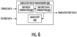
- the simulated track management 600 service includes one or more sub-services (each an individual service) such as a simulated track generation 602 service, a simulated first data generation 604 service and/or a main loop 606 service.
- the simulated track generation service is configured to generate a trajectory of a simulated moving object, which may be defined by a series of waypoints (positions) and velocities of the simulated moving object.
- the trajectory of the simulated moving object may follow a random route, or the route may be pre-defined and provided by configuration data.
- a conflict may be specified for the simulated moving object; and in some of these examples, the simulated track generation service may generate the trajectory of the simulated moving object further using a route of the robot 204, and/or the state data that describes the position and velocity of the robot, and that may be provided by the second data.
- the simulated first data generation 604 service is configured to generate simulated first data from the trajectory of the simulated moving object. Similar to the first data described above, the simulated first data indicates position and velocity of the simulated moving object, or the position and the velocity are determined from the simulated first data.
- the simulated first data may be formatted as sensor data (e.g., radar, lidar, infrared sensor, camera, ADS-B) and expressed in any of a number of data formats (e.g., first data format, second data format). In some examples, the simulated first data may further include an amount of acceptable noise that may otherwise be expected of the first data.
- the main loop 606 service is configured to publish the simulated first data such as for other services (e.g., services 500 ).
- the main loop service is configured to publish the simulated first data based on the route of the robot 204, and/or the state data that describes the position and velocity of the robot.
- the main loop service may publish the simulated first data when the position of the simulated moving object is within the given region of interest 418 that includes the robot, or when the simulated moving object is otherwise considered nearby the robot.
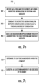
- FIGS. 7A , 7B , 7C , 7D and 7E are flowcharts illustrating various steps in a method 700 of detecting conflict along a route for a robot to travel, according to examples of the present disclosure.
- the method includes receiving first data that indicates a first position and a first velocity of one or more nearby moving objects, or from which the first position and the first velocity of the one or more nearby moving objects are determined.
- the method then includes a number of steps for each nearby moving object of the one or more nearby moving objects.
- the method includes generating a vector projection of the nearby moving object from the first position and using the first velocity of the nearby moving object, the vector projection corresponding to a predicted trajectory of the nearby moving object, as shown at block 704.
- the method 700 includes generating a trajectory of the robot on the route for the robot to travel, and from second data that indicates a second position and a second velocity of the robot, as shown at block 706.
- the route for the robot to travel is described by at least one of a route command, a flight plan or a mission route; and in some of these examples, the trajectory of the robot is generated using the at least one of the route command, the flight plan or the mission route.
- the method 700 includes performing a comparison of the nearby moving object and the robot on respectively the predicted trajectory of the nearby moving object and the trajectory of the robot.
- the comparison is performed to detect a conflict when the nearby moving object is within a clear region that includes the robot, and a time to closest point of approach between nearby moving object and the robot is less than a time threshold value.
- the method then includes, when the conflict is detected, outputting an indication of the conflict for use in at least one of guidance, navigation or control of the robot to avoid the conflict, as shown at block 710.
- performing the comparison at block 708 includes performing a stepwise comparison that includes a plurality of timesteps.
- a timestep of a plurality of timesteps the stepwise comparison includes determining updated positions and updated velocities of the nearby moving object and the robot on respectively the predicted trajectory of the nearby moving object and the trajectory of the robot, as shown at block 712.
- the stepwise comparison includes determining if the nearby moving object is within a clear region that includes the robot, and if a time to closest point of approach between nearby moving object and the robot is less than a time threshold value, as shown at block 714.
- the clear region is dynamic in size in that the clear region is different in size for a later one of the plurality of timesteps relative to an earlier one of the plurality of timesteps. A conflict is detected when the nearby moving object is within the clear region, and the time to closest point of approach is less than the time threshold value, as shown at block 716.
- receiving the first data at block 702 includes receiving the first data from a sensor operatively in communication with the robot and having a first data format, or data-linked from the nearby moving object and having a second data format, as shown at block 702A of FIG. 7B .
- the first data is transformed from the first data format or the second data format to a third data format from which the vector projection and thereby the predicted trajectory of the nearby moving object is generated, as shown at block 702B.
- the first data may be applied to one or more filters before the vector projection and thereby the predicted trajectory of the nearby moving object is generated.
- the first data is applied to a filter that passes the first data for generating the vector projection at block 704 only when the first position of the nearby moving object is within a given region of interest that includes the robot at the second position, as shown at block 718.
- the first data further indicates a time and an accuracy of the first data, and the first data is applied to a filter that passes the first data for generating the vector projection only when the time is within a time threshold of current time, and the accuracy is within an accuracy threshold, as shown at block 720.
- the one or more nearby moving objects are a plurality of nearby moving objects
- the first data is applied to a filter that passes the first data for generating the vector projection at block 704 for only a given number of the plurality of nearby moving objects, as shown at block 722.
- the vector projection and thereby the predicted trajectory of the nearby moving object is generated for each nearby moving object.
- the first position and the first velocity are observations of position and velocity
- receiving the first data at block 702 includes receiving data from multiple sources including respective observations of position and velocity of the one or more nearby moving objects, as shown at block 702C of FIG. 7D .
- the respective observations of position and velocity are correlated; and in some examples, the respective observations have at least a threshold degree of correlation that indicates the respective observations are for the nearby moving object, as shown at block 702D. Based on this threshold degree of correlation, an observation of position and velocity is selected from the respective observations as the respectively first position and the first velocity of the nearby moving object, as shown at block 702E.
- the first data further indicates accuracies of the respective observations of position and velocity, and the observation that is selected is the observation that is most accurate as indicated by a highest one of the accuracies.
- the method 700 further includes determining at least one maneuver to avoid the conflict, as shown at block 724 of FIG. 7E .
- the method includes causing the robot to execute the at least one maneuver, as shown at block 726.
- FIG. 8 illustrates an apparatus 800 according to some examples of the present disclosure.
- An exemplary apparatus of the present disclosure may comprise, include or be embodied in one or more fixed or portable electronic devices.
- the apparatus may include one or more of each of a number of components such as, for example, processing circuitry 802 (e.g., processor unit) connected to a memory 804 (e.g., storage device).
- processing circuitry 802 e.g., processor unit
- memory 804 e.g., storage device
- the processing circuitry 802 may be composed of one or more processors alone or in combination with one or more memories.
- the processing circuitry may be any piece of computer hardware that is capable of processing information such as, for example, data, computer programs and/or other suitable electronic information.
- the processing circuitry is composed of a collection of electronic circuits some of which may be packaged as an integrated circuit or multiple interconnected integrated circuits (an integrated circuit at times more commonly referred to as a "chip").
- the processing circuitry may be configured to execute computer programs, which may be stored onboard the processing circuitry or otherwise stored in the memory 804 (of the same or another apparatus).
- the processing circuitry 802 may be a number of processors, a multi-core processor or some other type of processor, depending on the particular implementation. Further, the processing circuitry may be implemented using a number of heterogeneous processor systems in which a main processor is present with one or more secondary processors on a single chip. As another illustrative example, the processing circuitry may be a symmetric multi-processor system containing multiple processors of the same type. In yet another example, the processing circuitry may be embodied as or otherwise include one or more ASICs, FPGAs or the like. Thus, although the processing circuitry may be capable of executing a computer program to perform one or more functions, the processing circuitry of various examples may be capable of performing one or more functions without the aid of a computer program. In either instance, the processing circuitry may be appropriately programmed to perform functions or operations according to examples of the present disclosure.
- the memory 804 may be any piece of computer hardware that is capable of storing information such as, for example, data, computer programs (e.g., computer-readable program code 806 ) and/or other suitable information either on a temporary basis and/or a permanent basis.
- the memory may include volatile and/or non-volatile memory, and may be fixed or removable. Examples of suitable memory include random access memory (RAM), read-only memory (ROM), a hard drive, a flash memory, a thumb drive, a removable computer diskette, an optical disk, a magnetic tape or some combination of the above.
- Optical disks may include compact disk - read only memory (CD-ROM), compact disk - read/write (CD-R/W), DVD or the like.
- the memory may be referred to as a computer-readable storage medium.
- the computer-readable storage medium is a non-transitory device capable of storing information, and is distinguishable from computer-readable transmission media such as electronic transitory signals capable of carrying information from one location to another.
- Computer-readable medium as described herein may refer to a computer-readable storage medium or computer-readable transmission medium.
- the processing circuitry 802 may also be connected to one or more interfaces for displaying, transmitting and/or receiving information.
- the interfaces may include a communications interface 808 (e.g., communications unit) and/or one or more user interfaces.
- the communications interface may be configured to transmit and/or receive information, such as to and/or from other apparatus(es), network(s) or the like.
- the communications interface may be configured to transmit and/or receive information by physical (wired) and/or wireless communications links. Examples of suitable communication interfaces include a network interface controller (NIC), wireless NIC (WNIC) or the like.
- NIC network interface controller
- WNIC wireless NIC
- the user interfaces may include a display 810 and/or one or more user input interfaces 812 (e.g., input/output unit).
- the display may be configured to present or otherwise display information to a user, suitable examples of which include a liquid crystal display (LCD), light-emitting diode display (LED), plasma display panel (PDP) or the like.
- the user input interfaces may be wired or wireless, and may be configured to receive information from a user into the apparatus, such as for processing, storage and/or display. Suitable examples of user input interfaces include a microphone, image or video capture device, keyboard or keypad, joystick, touch-sensitive surface (separate from or integrated into a touchscreen), biometric sensor or the like.
- the user interfaces may further include one or more interfaces for communicating with peripherals such as printers, scanners or the like.
- program code instructions may be stored in memory, and executed by processing circuitry that is thereby programmed, to implement functions of the systems, subsystems, tools and their respective elements described herein.
- any suitable program code instructions may be loaded onto a computer or other programmable apparatus from a computer-readable storage medium to produce a particular machine, such that the particular machine becomes a means for implementing the functions specified herein.
- These program code instructions may also be stored in a computer-readable storage medium that can direct a computer, a processing circuitry or other programmable apparatus to function in a particular manner to thereby generate a particular machine or particular article of manufacture.
- the instructions stored in the computer-readable storage medium may produce an article of manufacture, where the article of manufacture becomes a means for implementing functions described herein.
- the program code instructions may be retrieved from a computer-readable storage medium and loaded into a computer, processing circuitry or other programmable apparatus to configure the computer, processing circuitry or other programmable apparatus to execute operations to be performed on or by the computer, processing circuitry or other programmable apparatus.
- Retrieval, loading and execution of the program code instructions may be performed sequentially such that one instruction is retrieved, loaded and executed at a time. In some examples, retrieval, loading and/or execution may be performed in parallel such that multiple instructions are retrieved, loaded, and/or executed together. Execution of the program code instructions may produce a computer-implemented process such that the instructions executed by the computer, processing circuitry or other programmable apparatus provide operations for implementing functions described herein.
- an apparatus 800 may include a processing circuitry 802 and a computer-readable storage medium or memory 804 coupled to the processing circuitry, where the processing circuitry is configured to execute computer-readable program code 806 stored in the memory. It will also be understood that one or more functions, and combinations of functions, may be implemented by special purpose hardware-based computer systems and/or processing circuitry which perform the specified functions, or combinations of special purpose hardware and program code instructions.
Landscapes
- Engineering & Computer Science (AREA)
- Aviation & Aerospace Engineering (AREA)
- Physics & Mathematics (AREA)
- General Physics & Mathematics (AREA)
- Radar, Positioning & Navigation (AREA)
- Remote Sensing (AREA)
- Automation & Control Theory (AREA)
- Business, Economics & Management (AREA)
- Health & Medical Sciences (AREA)
- Artificial Intelligence (AREA)
- Evolutionary Computation (AREA)
- Game Theory and Decision Science (AREA)
- Medical Informatics (AREA)
- Control Of Position, Course, Altitude, Or Attitude Of Moving Bodies (AREA)
Claims (14)
- Verfahren (700), optional computerimplementiertes Verfahren, zum Erkennen von Konflikten (424) entlang einer Route (402), die ein Roboter (204) zurücklegen soll, wobei das Verfahren (700) umfasst:Empfangen von ersten Daten, die eine erste Position (406) und eine erste Geschwindigkeit (408) eines oder mehrerer sich in der Nähe bewegender Objekte (404) anzeigen, oder aus denen die erste Position (406) und die erste Geschwindigkeit (408) der ein oder mehreren sich in der Nähe bewegenden Objekte (404) bestimmt werden, wobei die ersten Daten von einer Mehrzahl verschiedener Sensoren erfasste Sensordaten umfassen und aus mehreren Beobachtungen der ein oder mehreren sich in der Nähe bewegenden Objekte (404) gefiltert und/oder korreliert werden; undfür jedes sich in der Nähe bewegende Objekt (404) der ein oder mehreren sich in der Nähe bewegenden Objekte (404):Erzeugen einer Vektorprojektion des sich in der Nähe bewegenden Objekts (404) von der ersten Position (406) und unter Verwendung der ersten Geschwindigkeit (408) des sich in der Nähe bewegenden Objekts (404), wobei die Vektorprojektion einer vorhergesagten Trajektorie (410, 412) des sich in der Nähe bewegenden Objekts (404) entspricht;Erzeugen einer Trajektorie (410, 412) des Roboters (204) auf der Route (402), die der Roboter (204) zurücklegen soll, wobei die Trajektorie (410, 412) aus zweiten Daten erzeugt wird, die eine zweite Position (414) und eine zweite Geschwindigkeit (416) des Roboters (204) angeben;Durchführen eines Vergleichs des sich in der Nähe bewegenden Objekts (404) und des Roboters (204) auf der vorhergesagten Trajektorie (410, 412) des sich in der Nähe bewegenden Objekts (404) bzw. der Trajektorie (410, 412) des Roboters (204), wobei der Vergleich durchgeführt wird, um einen Konflikt (424) zu erkennen, wenn sich das sich in der Nähe bewegende Objekt (404) innerhalb eines freien Bereichs (422) befindet, der den Roboter (204) einschließt, und eine Zeit bis zum Punkt der größten Annäherung zwischen dem sich in der Nähe bewegenden Objekt (404) und dem Roboter (204) kürzer ist als ein Zeitschwellenwert; undwenn der Konflikt (424) erkannt wird, Ausgeben einer Anzeige des Konflikts (424) zur Verwendung bei Führung, Navigation und/oder Steuerung des Roboters (204), um den Konflikt (424) zu vermeiden;dadurch gekennzeichnet, dassdas Durchführen des Vergleichs das Durchführen eines schrittweisen Vergleichs umfasst, der eine Mehrzahl von Zeitschritten umfasst, und der freie Bereich (422) eine dynamische Größe aufweist, um eine Sensorunsicherheit in einem oder mehreren Sensoren der Mehrzahl verschiedener Sensoren zu berücksichtigen, und dass der freie Bereich (422) für einen späteren der Mehrzahl von Zeitschritten im Verhältnis zu einem früheren der Mehrzahl von Zeitschritten eine unterschiedliche Größe aufweist, um eine Unsicherheit in den ersten Daten zu berücksichtigen.
- Verfahren (700) nach Anspruch 1, bei dem die Mehrzahl unterschiedlicher Sensoren Radar-, Lidar-, Infrarot-, Kamera- oder ADS-B-Sensoren umfasst.
- Verfahren (700) nach Anspruch 1 oder 2, bei dem die Route (402), die der Roboter (204) zurücklegen soll, durch einen Routenbefehl, einen Flugplan und/oder eine Missionsroute (402) beschrieben wird, und das Erzeugen der Trajektorie (410, 412) des Roboters (204) das Erzeugen der Trajektorie (410, 412) des Roboters (204) unter Verwendung des Routenbefehls, des Flugplans und/oder der Missionsroute (402) umfasst.
- Verfahren (700) nach einem der Ansprüche 1 bis 3, bei dem das Empfangen der ersten Daten umfasst:Empfangen der ersten Daten von einem Sensor, der in Wirkverbindung mit dem Roboter (204) steht, und die ein erstes Datenformat aufweisen, oder von Daten, die von dem sich in der Nähe bewegenden Objekt (404) stammen und ein zweites Datenformat aufweisen; undUmwandeln der ersten Daten aus dem ersten Datenformat oder dem zweiten Datenformat in ein drittes Datenformat, aus dem die Vektorprojektion und dadurch die vorhergesagte Trajektorie (410, 412) des sich in der Nähe bewegenden Objekts (404) erzeugt wird.
- Verfahren (700) nach einem der Ansprüche 1 bis 4, das ferner umfasst:
Eingeben der ersten Daten in ein Filter (510), das die ersten Daten nur dann zur Erzeugung der Vektorprojektion durchlässt, wenn die erste Position (406) des sich in der Nähe bewegenden Objekts (404) innerhalb eines gegebenen Bereichs von Interesse (418) liegt, der den Roboter (204) an der zweiten Position (414) einschließt. - Verfahren (700) nach einem der Ansprüche 1 bis 5, bei dem die ersten Daten ferner eine Zeit und eine Genauigkeit der ersten Daten angeben und das Verfahren (700) ferner umfasst:
Eingeben der ersten Daten in ein Filter (510), das die ersten Daten nur dann zur Erzeugung der Vektorprojektion durchlässt, wenn die Zeit innerhalb eines Zeitschwellenwerts der aktuellen Zeit liegt und die Genauigkeit innerhalb eines Genauigkeitsschwellenwerts liegt. - Verfahren (700) nach einem der Ansprüche 1 bis 6, bei dem die erste Position (406) und die erste Geschwindigkeit (408) Beobachtungen der Position und Geschwindigkeit sind und das Empfangen der ersten Daten umfasst:Empfangen von Daten von mehreren Quellen, einschließlich jeweiliger Beobachtungen der Position und Geschwindigkeit der ein oder mehreren sich in der Nähe bewegenden Objekte (404);Korrelieren der jeweiligen Beobachtungen von Position und Geschwindigkeit; undbasierend darauf, dass die jeweiligen Beobachtungen einen Schwellenwert für den Korrelationsgrad aufweisen, der anzeigt, dass die jeweiligen Beobachtungen für das sich in der Nähe bewegende Objekt (404) gelten, Auswählen einer Beobachtung von Position und Geschwindigkeit aus den jeweiligen Beobachtungen als die jeweils erste Position (406) und die erste Geschwindigkeit (408) des sich in der Nähe bewegenden Objekts (404).
- Verfahren (700) nach Anspruch 7, bei dem die ersten Daten ferner Genauigkeiten der jeweiligen Beobachtungen von Position und Geschwindigkeit angeben und das Auswählen der Beobachtung das Auswählen derjenigen Beobachtung umfasst, die, wie durch eine höchste der Genauigkeiten angegeben, die genaueste ist.
- Verfahren (700) nach einem der Ansprüche 1 bis 8, bei dem die ein oder mehreren sich in der Nähe bewegenden Objekte (404) eine Mehrzahl von sich in der Nähe bewegenden Objekten (404) sind und
wobei das Verfahren (700) ferner das Eingeben der ersten Daten in ein Filter (510) umfasst, das die ersten Daten zum Erzeugen der Vektorprojektion nur für eine gegebene Anzahl der Mehrzahl von sich in der Nähe bewegenden Objekten (404) durchlässt, und wobei die Vektorprojektion und dadurch die vorhergesagte Trajektorie (410, 412) des sich in der Nähe bewegenden Objekts (404) für jedes sich in der Nähe bewegende Objekt (404) erzeugt wird. - Verfahren (700) nach einem der Ansprüche 1 bis 9, das ferner umfasst:Bestimmen mindestens eines Manövers zur Vermeidung des Konflikts (424); undVeranlassen, dass der Roboter (204) das mindestens eine Manöver ausführt.
- Verfahren (700) nach einem der Ansprüche 1 bis 10, wobei der Roboter (204) ein unbemanntes Bodenfahrzeug (UGV), ein unbemanntes Luftfahrzeug (UAV), ein unbemanntes Oberflächenfahrzeug (USV), ein unbemanntes Unterwasserfahrzeug (UUV) oder ein unbemanntes Raumfahrzeug umfasst.
- Computerprogramm, das Computerprogrammanweisungen umfasst, die, wenn sie von einem Computerprozessor ausgeführt werden, den Computerprozessor veranlassen, das Verfahren nach einem der Ansprüche 1 bis 11 auszuführen.
- Computerlesbares Medium, auf dem das Computerprogramm nach Anspruch 12 gespeichert ist.
- Vorrichtung (800) zum Erkennen von Konflikten (424) entlang einer Route (402), die ein Roboter (204) zurücklegen soll, wobei die Vorrichtung (800) umfasst:einen Speicher (804), in dem ein computerlesbarer Programmcode gespeichert ist; undeine Verarbeitungsschaltung (802), die konfiguriert ist, um auf den Speicher (804) zuzugreifen und den computerlesbaren Programmcode auszuführen, um die Vorrichtung (800) zu veranlassen, das Verfahren nach einem der Ansprüche 1 bis 11 auszuführen.
Applications Claiming Priority (2)
| Application Number | Priority Date | Filing Date | Title |
|---|---|---|---|
| US202063059393P | 2020-07-31 | 2020-07-31 | |
| US17/148,127 US20250265936A1 (en) | 2020-07-31 | 2021-01-13 | Detecting Conflict Along a Route of a Robot |
Publications (2)
| Publication Number | Publication Date |
|---|---|
| EP3945396A1 EP3945396A1 (de) | 2022-02-02 |
| EP3945396B1 true EP3945396B1 (de) | 2025-04-23 |
Family
ID=77050894
Family Applications (1)
| Application Number | Title | Priority Date | Filing Date |
|---|---|---|---|
| EP21187642.0A Active EP3945396B1 (de) | 2020-07-31 | 2021-07-26 | Erkennung von konflikten entlang einer route eines roboters |
Country Status (3)
| Country | Link |
|---|---|
| US (1) | US20250265936A1 (de) |
| EP (1) | EP3945396B1 (de) |
| CN (1) | CN114063633A (de) |
Families Citing this family (2)
| Publication number | Priority date | Publication date | Assignee | Title |
|---|---|---|---|---|
| US20250140123A1 (en) * | 2022-02-04 | 2025-05-01 | Zipline International Inc. | Tactical deconfliction system for unmanned aerial vehicles |
| CN117381805B (zh) * | 2023-12-13 | 2024-02-27 | 成都航空职业技术学院 | 一种面向冲突应对的机械臂运行控制方法和系统 |
Family Cites Families (9)
| Publication number | Priority date | Publication date | Assignee | Title |
|---|---|---|---|---|
| US8965679B2 (en) * | 2012-06-11 | 2015-02-24 | Honeywell International Inc. | Systems and methods for unmanned aircraft system collision avoidance |
| US9417325B1 (en) * | 2014-01-10 | 2016-08-16 | Google Inc. | Interface for accessing radar data |
| US9384667B2 (en) * | 2014-07-17 | 2016-07-05 | Honeywell International Inc. | Scalar product based spacing calculation |
| WO2018131153A1 (ja) * | 2017-01-16 | 2018-07-19 | 株式会社日立製作所 | 移動体制御装置および移動体の制御方法 |
| FR3070527B1 (fr) * | 2017-08-31 | 2020-11-06 | Airbus Helicopters | Procede et dispositif d'evitement d'un objet par detection de son rapprochement d'un aeronef |
| US10764911B2 (en) * | 2017-12-01 | 2020-09-01 | Renovo Motors, Inc. | Systems and methods for prioritizing data for autonomous mobility on demand |
| FR3087915B1 (fr) * | 2018-10-31 | 2021-09-17 | Thales Sa | Dispositif anticollision, systeme avionique de protection, procede d'anticollision et programme d'ordinateur associes |
| CN109739255B (zh) * | 2018-11-29 | 2020-11-24 | 北京航空航天大学 | 无人机的航行轨迹规划方法、装置及系统 |
| US11282397B2 (en) * | 2019-03-28 | 2022-03-22 | Fortem Technologies, Inc. | System and method for fusing asynchronous sensor tracks in a track fusion application |
-
2021
- 2021-01-13 US US17/148,127 patent/US20250265936A1/en active Pending
- 2021-07-26 EP EP21187642.0A patent/EP3945396B1/de active Active
- 2021-07-30 CN CN202110878627.7A patent/CN114063633A/zh active Pending
Also Published As
| Publication number | Publication date |
|---|---|
| CN114063633A (zh) | 2022-02-18 |
| EP3945396A1 (de) | 2022-02-02 |
| US20250265936A1 (en) | 2025-08-21 |
Similar Documents
| Publication | Publication Date | Title |
|---|---|---|
| US11835953B2 (en) | Adaptive autonomy system architecture | |
| US12190741B2 (en) | Conflict detection and avoidance along a current route of a robot | |
| US12482367B2 (en) | Reinforcement learning-based mid-air collision avoidance | |
| EP3945396B1 (de) | Erkennung von konflikten entlang einer route eines roboters | |
| EP4362002A1 (de) | System und verfahren zur erkennung und vermeidung von konflikten entlang einer aktuellen route eines fahrzeugs | |
| US20240419167A1 (en) | Conflict detection and avoidance for a robot based on perception uncertainty | |
| US20240265817A1 (en) | Conflict detection and avoidance for a robot with right-of-way rule compliant maneuver selection | |
| US20240310185A1 (en) | Evaluation of a ground region for landing a robot | |
| EP4354414A1 (de) | Kollisionsvermeidungssystem und -verfahren | |
| US12032370B2 (en) | Supporting an aircraft on a mission in which an intent of the aircraft is conveyed responsive to a lost-link event | |
| US20250157349A1 (en) | Conflict detection and avoidance for a robot with right-of-way rule compliant maneuver selection | |
| Ahn et al. | Design and Simulation of an Emergency Navigation System for Indoor Swarm Drones |
Legal Events
| Date | Code | Title | Description |
|---|---|---|---|
| PUAI | Public reference made under article 153(3) epc to a published international application that has entered the european phase |
Free format text: ORIGINAL CODE: 0009012 |
|
| STAA | Information on the status of an ep patent application or granted ep patent |
Free format text: STATUS: THE APPLICATION HAS BEEN PUBLISHED |
|
| AK | Designated contracting states |
Kind code of ref document: A1 Designated state(s): AL AT BE BG CH CY CZ DE DK EE ES FI FR GB GR HR HU IE IS IT LI LT LU LV MC MK MT NL NO PL PT RO RS SE SI SK SM TR |
|
| STAA | Information on the status of an ep patent application or granted ep patent |
Free format text: STATUS: REQUEST FOR EXAMINATION WAS MADE |
|
| 17P | Request for examination filed |
Effective date: 20220729 |
|
| RBV | Designated contracting states (corrected) |
Designated state(s): AL AT BE BG CH CY CZ DE DK EE ES FI FR GB GR HR HU IE IS IT LI LT LU LV MC MK MT NL NO PL PT RO RS SE SI SK SM TR |
|
| STAA | Information on the status of an ep patent application or granted ep patent |
Free format text: STATUS: EXAMINATION IS IN PROGRESS |
|
| 17Q | First examination report despatched |
Effective date: 20221128 |
|
| REG | Reference to a national code |
Ref country code: DE Ref legal event code: R079 Free format text: PREVIOUS MAIN CLASS: G05D0001100000 Ipc: G05D0001622000 Ref country code: DE Ref legal event code: R079 Ref document number: 602021029492 Country of ref document: DE Free format text: PREVIOUS MAIN CLASS: G05D0001100000 Ipc: G05D0001622000 |
|
| GRAP | Despatch of communication of intention to grant a patent |
Free format text: ORIGINAL CODE: EPIDOSNIGR1 |
|
| STAA | Information on the status of an ep patent application or granted ep patent |
Free format text: STATUS: GRANT OF PATENT IS INTENDED |
|
| RIC1 | Information provided on ipc code assigned before grant |
Ipc: G05D 109/22 20240101ALN20241007BHEP Ipc: G05D 1/622 20240101AFI20241007BHEP |
|
| INTG | Intention to grant announced |
Effective date: 20241028 |
|
| P01 | Opt-out of the competence of the unified patent court (upc) registered |
Free format text: CASE NUMBER: APP_61903/2024 Effective date: 20241119 |
|
| GRAS | Grant fee paid |
Free format text: ORIGINAL CODE: EPIDOSNIGR3 |
|
| GRAA | (expected) grant |
Free format text: ORIGINAL CODE: 0009210 |
|
| STAA | Information on the status of an ep patent application or granted ep patent |
Free format text: STATUS: THE PATENT HAS BEEN GRANTED |
|
| AK | Designated contracting states |
Kind code of ref document: B1 Designated state(s): AL AT BE BG CH CY CZ DE DK EE ES FI FR GB GR HR HU IE IS IT LI LT LU LV MC MK MT NL NO PL PT RO RS SE SI SK SM TR |
|
| REG | Reference to a national code |
Ref country code: GB Ref legal event code: FG4D |
|
| REG | Reference to a national code |
Ref country code: CH Ref legal event code: EP |
|
| REG | Reference to a national code |
Ref country code: DE Ref legal event code: R096 Ref document number: 602021029492 Country of ref document: DE |
|
| REG | Reference to a national code |
Ref country code: IE Ref legal event code: FG4D |
|
| REG | Reference to a national code |
Ref country code: NL Ref legal event code: MP Effective date: 20250423 |
|
| PG25 | Lapsed in a contracting state [announced via postgrant information from national office to epo] |
Ref country code: NL Free format text: LAPSE BECAUSE OF FAILURE TO SUBMIT A TRANSLATION OF THE DESCRIPTION OR TO PAY THE FEE WITHIN THE PRESCRIBED TIME-LIMIT Effective date: 20250423 |
|
| REG | Reference to a national code |
Ref country code: AT Ref legal event code: MK05 Ref document number: 1788371 Country of ref document: AT Kind code of ref document: T Effective date: 20250423 |
|
| PG25 | Lapsed in a contracting state [announced via postgrant information from national office to epo] |
Ref country code: PT Free format text: LAPSE BECAUSE OF FAILURE TO SUBMIT A TRANSLATION OF THE DESCRIPTION OR TO PAY THE FEE WITHIN THE PRESCRIBED TIME-LIMIT Effective date: 20250825 Ref country code: FI Free format text: LAPSE BECAUSE OF FAILURE TO SUBMIT A TRANSLATION OF THE DESCRIPTION OR TO PAY THE FEE WITHIN THE PRESCRIBED TIME-LIMIT Effective date: 20250423 Ref country code: ES Free format text: LAPSE BECAUSE OF FAILURE TO SUBMIT A TRANSLATION OF THE DESCRIPTION OR TO PAY THE FEE WITHIN THE PRESCRIBED TIME-LIMIT Effective date: 20250423 |
|
| PGFP | Annual fee paid to national office [announced via postgrant information from national office to epo] |
Ref country code: DE Payment date: 20250729 Year of fee payment: 5 |
|
| REG | Reference to a national code |
Ref country code: LT Ref legal event code: MG9D |
|
| PG25 | Lapsed in a contracting state [announced via postgrant information from national office to epo] |
Ref country code: GR Free format text: LAPSE BECAUSE OF FAILURE TO SUBMIT A TRANSLATION OF THE DESCRIPTION OR TO PAY THE FEE WITHIN THE PRESCRIBED TIME-LIMIT Effective date: 20250724 Ref country code: NO Free format text: LAPSE BECAUSE OF FAILURE TO SUBMIT A TRANSLATION OF THE DESCRIPTION OR TO PAY THE FEE WITHIN THE PRESCRIBED TIME-LIMIT Effective date: 20250723 |
|
| PG25 | Lapsed in a contracting state [announced via postgrant information from national office to epo] |
Ref country code: PL Free format text: LAPSE BECAUSE OF FAILURE TO SUBMIT A TRANSLATION OF THE DESCRIPTION OR TO PAY THE FEE WITHIN THE PRESCRIBED TIME-LIMIT Effective date: 20250423 |
|
| PG25 | Lapsed in a contracting state [announced via postgrant information from national office to epo] |
Ref country code: BG Free format text: LAPSE BECAUSE OF FAILURE TO SUBMIT A TRANSLATION OF THE DESCRIPTION OR TO PAY THE FEE WITHIN THE PRESCRIBED TIME-LIMIT Effective date: 20250423 |
|
| PGFP | Annual fee paid to national office [announced via postgrant information from national office to epo] |
Ref country code: GB Payment date: 20250728 Year of fee payment: 5 |
|
| PG25 | Lapsed in a contracting state [announced via postgrant information from national office to epo] |
Ref country code: HR Free format text: LAPSE BECAUSE OF FAILURE TO SUBMIT A TRANSLATION OF THE DESCRIPTION OR TO PAY THE FEE WITHIN THE PRESCRIBED TIME-LIMIT Effective date: 20250423 |
|
| PG25 | Lapsed in a contracting state [announced via postgrant information from national office to epo] |
Ref country code: AT Free format text: LAPSE BECAUSE OF FAILURE TO SUBMIT A TRANSLATION OF THE DESCRIPTION OR TO PAY THE FEE WITHIN THE PRESCRIBED TIME-LIMIT Effective date: 20250423 |
|
| PGFP | Annual fee paid to national office [announced via postgrant information from national office to epo] |
Ref country code: FR Payment date: 20250725 Year of fee payment: 5 |
|
| PG25 | Lapsed in a contracting state [announced via postgrant information from national office to epo] |
Ref country code: RS Free format text: LAPSE BECAUSE OF FAILURE TO SUBMIT A TRANSLATION OF THE DESCRIPTION OR TO PAY THE FEE WITHIN THE PRESCRIBED TIME-LIMIT Effective date: 20250723 |
|
| PG25 | Lapsed in a contracting state [announced via postgrant information from national office to epo] |
Ref country code: IS Free format text: LAPSE BECAUSE OF FAILURE TO SUBMIT A TRANSLATION OF THE DESCRIPTION OR TO PAY THE FEE WITHIN THE PRESCRIBED TIME-LIMIT Effective date: 20250823 |
|
| PG25 | Lapsed in a contracting state [announced via postgrant information from national office to epo] |
Ref country code: LV Free format text: LAPSE BECAUSE OF FAILURE TO SUBMIT A TRANSLATION OF THE DESCRIPTION OR TO PAY THE FEE WITHIN THE PRESCRIBED TIME-LIMIT Effective date: 20250423 |
|
| PG25 | Lapsed in a contracting state [announced via postgrant information from national office to epo] |
Ref country code: DK Free format text: LAPSE BECAUSE OF FAILURE TO SUBMIT A TRANSLATION OF THE DESCRIPTION OR TO PAY THE FEE WITHIN THE PRESCRIBED TIME-LIMIT Effective date: 20250423 Ref country code: SM Free format text: LAPSE BECAUSE OF FAILURE TO SUBMIT A TRANSLATION OF THE DESCRIPTION OR TO PAY THE FEE WITHIN THE PRESCRIBED TIME-LIMIT Effective date: 20250423 |
|
| PG25 | Lapsed in a contracting state [announced via postgrant information from national office to epo] |
Ref country code: CZ Free format text: LAPSE BECAUSE OF FAILURE TO SUBMIT A TRANSLATION OF THE DESCRIPTION OR TO PAY THE FEE WITHIN THE PRESCRIBED TIME-LIMIT Effective date: 20250423 |
|
| PG25 | Lapsed in a contracting state [announced via postgrant information from national office to epo] |
Ref country code: EE Free format text: LAPSE BECAUSE OF FAILURE TO SUBMIT A TRANSLATION OF THE DESCRIPTION OR TO PAY THE FEE WITHIN THE PRESCRIBED TIME-LIMIT Effective date: 20250423 |
|
| REG | Reference to a national code |
Ref country code: DE Ref legal event code: R097 Ref document number: 602021029492 Country of ref document: DE |
|
| PG25 | Lapsed in a contracting state [announced via postgrant information from national office to epo] |
Ref country code: RO Free format text: LAPSE BECAUSE OF FAILURE TO SUBMIT A TRANSLATION OF THE DESCRIPTION OR TO PAY THE FEE WITHIN THE PRESCRIBED TIME-LIMIT Effective date: 20250423 Ref country code: SK Free format text: LAPSE BECAUSE OF FAILURE TO SUBMIT A TRANSLATION OF THE DESCRIPTION OR TO PAY THE FEE WITHIN THE PRESCRIBED TIME-LIMIT Effective date: 20250423 |
|
| PG25 | Lapsed in a contracting state [announced via postgrant information from national office to epo] |
Ref country code: IT Free format text: LAPSE BECAUSE OF FAILURE TO SUBMIT A TRANSLATION OF THE DESCRIPTION OR TO PAY THE FEE WITHIN THE PRESCRIBED TIME-LIMIT Effective date: 20250423 |
|
| REG | Reference to a national code |
Ref country code: CH Ref legal event code: H13 Free format text: ST27 STATUS EVENT CODE: U-0-0-H10-H13 (AS PROVIDED BY THE NATIONAL OFFICE) Effective date: 20260224 |
|
| PLBE | No opposition filed within time limit |
Free format text: ORIGINAL CODE: 0009261 |
|
| STAA | Information on the status of an ep patent application or granted ep patent |
Free format text: STATUS: NO OPPOSITION FILED WITHIN TIME LIMIT |
|
| REG | Reference to a national code |
Ref country code: CH Ref legal event code: L10 Free format text: ST27 STATUS EVENT CODE: U-0-0-L10-L00 (AS PROVIDED BY THE NATIONAL OFFICE) Effective date: 20260304 |
|
| PG25 | Lapsed in a contracting state [announced via postgrant information from national office to epo] |
Ref country code: LU Free format text: LAPSE BECAUSE OF NON-PAYMENT OF DUE FEES Effective date: 20250726 |
|
| REG | Reference to a national code |
Ref country code: BE Ref legal event code: MM Effective date: 20250731 |
|
| 26N | No opposition filed |
Effective date: 20260126 |
|
| PG25 | Lapsed in a contracting state [announced via postgrant information from national office to epo] |
Ref country code: BE Free format text: LAPSE BECAUSE OF NON-PAYMENT OF DUE FEES Effective date: 20250731 |
|
| PG25 | Lapsed in a contracting state [announced via postgrant information from national office to epo] |
Ref country code: CH Free format text: LAPSE BECAUSE OF NON-PAYMENT OF DUE FEES Effective date: 20250731 |