EP3945352B1 - Adapterspitze und mikroskopsystem zur inspektion von faseroptischen steckerendflächen - Google Patents
Adapterspitze und mikroskopsystem zur inspektion von faseroptischen steckerendflächen Download PDFInfo
- Publication number
- EP3945352B1 EP3945352B1 EP21188072.9A EP21188072A EP3945352B1 EP 3945352 B1 EP3945352 B1 EP 3945352B1 EP 21188072 A EP21188072 A EP 21188072A EP 3945352 B1 EP3945352 B1 EP 3945352B1
- Authority
- EP
- European Patent Office
- Prior art keywords
- optical
- fiber
- endface
- connector
- lens
- Prior art date
- Legal status (The legal status is an assumption and is not a legal conclusion. Google has not performed a legal analysis and makes no representation as to the accuracy of the status listed.)
- Active
Links
Images






Classifications
-
- G—PHYSICS
- G02—OPTICS
- G02B—OPTICAL ELEMENTS, SYSTEMS OR APPARATUS
- G02B6/00—Light guides; Structural details of arrangements comprising light guides and other optical elements, e.g. couplings
- G02B6/24—Coupling light guides
- G02B6/36—Mechanical coupling means
- G02B6/38—Mechanical coupling means having fibre to fibre mating means
- G02B6/3807—Dismountable connectors, i.e. comprising plugs
- G02B6/381—Dismountable connectors, i.e. comprising plugs of the ferrule type, e.g. fibre ends embedded in ferrules, connecting a pair of fibres
- G02B6/3825—Dismountable connectors, i.e. comprising plugs of the ferrule type, e.g. fibre ends embedded in ferrules, connecting a pair of fibres with an intermediate part, e.g. adapter, receptacle, linking two plugs
-
- G—PHYSICS
- G02—OPTICS
- G02B—OPTICAL ELEMENTS, SYSTEMS OR APPARATUS
- G02B6/00—Light guides; Structural details of arrangements comprising light guides and other optical elements, e.g. couplings
- G02B6/24—Coupling light guides
- G02B6/36—Mechanical coupling means
- G02B6/38—Mechanical coupling means having fibre to fibre mating means
- G02B6/3807—Dismountable connectors, i.e. comprising plugs
- G02B6/3833—Details of mounting fibres in ferrules; Assembly methods; Manufacture
- G02B6/385—Accessories for testing or observation of connectors
-
- G—PHYSICS
- G02—OPTICS
- G02B—OPTICAL ELEMENTS, SYSTEMS OR APPARATUS
- G02B21/00—Microscopes
- G02B21/0004—Microscopes specially adapted for specific applications
- G02B21/0008—Microscopes having a simple construction, e.g. portable microscopes
-
- G—PHYSICS
- G02—OPTICS
- G02B—OPTICAL ELEMENTS, SYSTEMS OR APPARATUS
- G02B21/00—Microscopes
- G02B21/0004—Microscopes specially adapted for specific applications
- G02B21/0016—Technical microscopes, e.g. for inspection or measuring in industrial production processes
-
- G—PHYSICS
- G02—OPTICS
- G02B—OPTICAL ELEMENTS, SYSTEMS OR APPARATUS
- G02B23/00—Telescopes, e.g. binoculars; Periscopes; Instruments for viewing the inside of hollow bodies; Viewfinders; Optical aiming or sighting devices
- G02B23/24—Instruments or systems for viewing the inside of hollow bodies, e.g. fibrescopes
- G02B23/2407—Optical details
- G02B23/2446—Optical details of the image relay
-
- G—PHYSICS
- G02—OPTICS
- G02B—OPTICAL ELEMENTS, SYSTEMS OR APPARATUS
- G02B6/00—Light guides; Structural details of arrangements comprising light guides and other optical elements, e.g. couplings
- G02B6/24—Coupling light guides
- G02B6/36—Mechanical coupling means
- G02B6/38—Mechanical coupling means having fibre to fibre mating means
- G02B6/3807—Dismountable connectors, i.e. comprising plugs
- G02B6/3833—Details of mounting fibres in ferrules; Assembly methods; Manufacture
- G02B6/3853—Lens inside the ferrule
-
- G—PHYSICS
- G02—OPTICS
- G02B—OPTICAL ELEMENTS, SYSTEMS OR APPARATUS
- G02B6/00—Light guides; Structural details of arrangements comprising light guides and other optical elements, e.g. couplings
- G02B6/24—Coupling light guides
- G02B6/36—Mechanical coupling means
- G02B6/38—Mechanical coupling means having fibre to fibre mating means
- G02B6/3807—Dismountable connectors, i.e. comprising plugs
- G02B6/381—Dismountable connectors, i.e. comprising plugs of the ferrule type, e.g. fibre ends embedded in ferrules, connecting a pair of fibres
- G02B6/3818—Dismountable connectors, i.e. comprising plugs of the ferrule type, e.g. fibre ends embedded in ferrules, connecting a pair of fibres of a low-reflection-loss type
- G02B6/3822—Dismountable connectors, i.e. comprising plugs of the ferrule type, e.g. fibre ends embedded in ferrules, connecting a pair of fibres of a low-reflection-loss type with beveled fibre ends
Definitions
- the present description generally relates to inspection of optical-fiber connector endfaces and more specifically to adapter tips, to be used in conjunction with an optical-fiber connector endface inspection microscope and suitable for imaging angled-polished optical-fiber connectors.
- optical-fiber connector endface inspection microscopes are commonly employed to visually inspect and/or to analyze the optical-fiber endface of an optical-fiber connector at installation or during maintenance of optical communication networks, in order to verify the quality of the optical-fiber connection.
- inspection microscopes are typically employed with interchangeable adapter tips so as to allow inspection of various types of optical-fiber connectors directly or as inserted in an optical-fiber connector adapter.
- US Patent 8,976,345 to ZHOU et al. describes a fiber inspection adapter tip using a lens or lens system within the tip. The tip lens or lens system is tilted relative to the inspected angled-polished optical-fiber endface, i.e., the lens axis is not normal to the optical-fiber endface. The inspection microscope is also tilted relative to both the tip lens or lens system and the optical-fiber endface.
- US Patent 9,880,359 to Morin-Drouin et al. describes a fiber inspection adapter tip using at least one relay lens within the tip. The lens axis of the relay lens is offset relative to the optical-fiber endface so as to deviate light reflected from the optical-fiber endface, towards the optical-fiber axis of the connector.
- an adapter tip to be employed with an optical-fiber connector-endface inspection microscope and an optical-fiber connector endface inspection microscope system suitable for imaging and/or analyzing the optical-fiber endface of an angled-polished optical-fiber connector recessed within a connector adapter. Because of the angle formed between the normal of the optical-fiber endface and the optical-fiber axis of the connector (which coincides with the central axis of the connector ferrule), the object plane to be imaged is oriented at an angle (of 8 degrees in the case of APC connectors in the industry) relative to the central axis of the narrow channel formed within the connector adapter.
- the adapter tip comprises a relay optical system comprising a Rhomboid prism of which the function is to laterally shift light coming from the optical-fiber endface through reflection of the illumination light (mostly specular but also potentially diffuse) - referred to hereinafter as the object beam - in order to allow it to exit the connector adapter and be collected by the inspection microscope.
- a relay optical system comprising a Rhomboid prism of which the function is to laterally shift light coming from the optical-fiber endface through reflection of the illumination light (mostly specular but also potentially diffuse) - referred to hereinafter as the object beam - in order to allow it to exit the connector adapter and be collected by the inspection microscope.
- the relay optical system prevents a substantial proportion of the object beam to be obstructed by the inside walls of the connector adapter and therefore allows a more substantial portion of the object beam reflected from the optical-fiber endface to exit the connector adapter and be collected by the inspection microscope.
- the relay optical system may also allow the inspection microscope to be mostly aligned and parallel with the inspected optical-fiber connector.
- this alignment minimizes interference of the inspection microscope with neighboring optical-fiber connectors.
- an adapter tip to be employed with an optical-fiber connector endface inspection microscope for imaging an optical-fiber endface of an angled-polished optical-fiber connector recessed within a connector adapter.
- the adapter tip comprises:
- an optical-fiber connector endface inspection microscope system for imaging an optical-fiber endface of an angled-polished optical-fiber connector recessed in a connector adapter.
- the microscope system comprises:
- the Rhomboid prism may laterally shift the light beam reflected from the angled-polished optical-fiber endface towards a direction opposite to the vector rejection of the normal to the optical-fiber endface on the optical-fiber axis of the connector.
- the relay optical system may further comprise at least a first relay lens and a second relay lens, the first relay lens being disposed proximate to the optical-fiber endface so as to receive light reflected from said optical-fiber endface during inspection and the second relay lens being disposed spaced apart from the first relay lens to further relay the light beam to the optical axis of the optical-fiber connector endface inspection microscope.
- the first relay lens may be disposed so as to directly receive light reflected from said optical-fiber endface during inspection and the Rhomboid prism be disposed between said first relay lens and the second relay lens in order to laterally shift the light beam reflected from the optical-fiber endface and relayed by the first relay lens, towards the lens axis of the second relay lens.
- a lens axis of the first relay lens may be aligned to a center of the optical-fiber endface.
- a lens axis of the first relay lens may be offset to a centerline of the object beam, towards a direction corresponding to the vector rejection of the normal to the optical-fiber endface on the optical-fiber axis of the connector, so as to deviate the light beam reflected from the optical-fiber endface towards the optical-fiber axis of the connector.
- the lens axis of the second relay lens may be offset relative to a center of the optical-fiber endface towards a direction opposite to the vector rejection of the normal to the optical-fiber endface on the optical-fiber axis of the connector, in order to receive the light beam laterally displaced by the Rhomboid prism.
- a lens axis of the first relay lens and the lens axis of the second relay lens may be both parallel to an optical-fiber axis of the connector.
- a lens axis of the objective lens may be parallel to said optical-fiber axis during inspection.
- a lens axis of the objective lens of the optical-fiber connector endface inspection microscope may be offset relative to the lens axis of the second relay lens during inspection.
- the relay optical system may produce an intermediate image plane between the second relay lens and an objective lens of the optical-fiber connector endface inspection microscope.
- the adapter tip may receive illumination light from the optical-fiber connector endface inspection microscope during inspection in order to image the optical-fiber endface and the relay optical system may redirect the illumination light to the optical-fiber endface.
- optical-fiber connector endface inspection microscope and the “optical-fiber connector endface inspection microscope system” may be referred to respectively as an “inspection microscope” and an “inspection microscope system”.
- optical-fiber connector endface may be referred to as a “connector endface” or simply “endface”.
- the terms “light” and “optical” are used to refer to radiation in any appropriate region of the electromagnetic spectrum. More particularly, the terms “light” and “optical” are not limited to visible light, but can include, for example, the infrared wavelength range.
- the illumination source can emit light in the blue region, e.g., at about 470 nm, or any other suitable spectral region within the visible spectrum, the near ultraviolet spectrum or the near infrared spectrum.
- these wavelength ranges are provided for illustrative purposes only and that the present techniques may operate beyond these ranges.
- word modifiers such as “substantially” and “about” which modify a value, condition, relationship or characteristic of a feature or features of an embodiment, should be understood to mean that the value, condition, relationship or characteristic is defined to within tolerances that are acceptable for proper operation of this embodiment in the context its intended application.
- connection or coupling refers to any connection or coupling, either direct or indirect, between two or more elements.
- the connection or coupling between the elements may be mechanical, physical, operational, electrical or a combination thereof.
- Fig. 1 shows a cross-sectional view of a connector adapter 100 suitable for interconnecting optical-fiber connectors of connector type known in the industry as MDC-APC connectors. It should be noted that Fig. 1 is simplified such that some elements (notably of the optical-fiber connector) may be omitted in order to emphasize the parts that are relevant to the present description.
- optical-fiber connectors to be inspected using an optical-fiber connector endface inspection microscope are inserted in a connector adapter such as that of connector adapter 100.
- connector adapters are used to interconnect two optical fibers terminated by optical-fiber connectors such as connector 102.
- optical-fiber connectors In order for the endfaces 104 of the optical fibers to be brought into close contact, optical-fiber connectors employ fiber-optic ferrules 106 in which the terminated portion of an optical fiber is inserted.
- the fiber-optic ferrule 106 and optical fiber assembly is polished at the termination, either perpendicularly to the optical fiber axis or at an 8-degree angle in the case of Angled-polished Physical Contact (APC) connectors, so as to form a ferrule endface 104 enclosing, usually in its center, the optical-fiber endface.
- the connector adapter 100 defines two opposing ends 110, 112 opening to respective connector-receiving channels 114, 116 reaching at a connector interface in the center of the connector adapter 100.
- a mating sleeve 120 defining a ferrule receiving channel 122 in continuity and properly aligned with both connector-receiving channels 114, 116.
- Two optical-fiber connectors can be interconnected by inserting a first connector via the first end 110 into connector-receiving channel 114 and a second connector (not shown) via the second end 112 into connector-receiving channel 116.
- angular alignment of the optical-fiber connectors is provided by the somewhat rectangular shape of the connector-receiving channels 114, 116.
- the connector 102 to be inspected is generally inserted in the connector adapter 100 via one end 110 and through a connector-receiving channel 114 such that the surface of the optical-fiber endface 104 to be imaged lies at the connector interface recessed within the connector adapter 100. Imaging is therefore performed through the other end 112, i.e. the open end, and the other connector-receiving channel 116.
- the object beam 126 reflected from the endface should be appropriately collected by the inspection microscope objective lens.
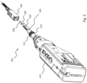
- an adapter tip 200 to be employed with an inspection microscope 201 suitable for imaging the optical-fiber endface 104 of an angled-polished optical-fiber connector 102 (see Fig. 7 ), deeply recessed within a connector adapter 100.
- the inspection microscope 201 is an inspection microscope 201 adapted to be employed with a variety of interchangeable adapter tips so as to allow inspection of various types of optical-fiber connectors directly or as inserted in an optical-fiber connector adapter.
- the adapter tip 200 and the inspection microscope 201 together form an inspection microscope system 202.
- the most common adapter tips employed for inspecting, e.g., FC/PC or FC/APC connectors are mostly mechanical adapters and therefore do not include any optical elements.
- the input lens of the inspection microscope 201 is referred to herein as the "objective lens”.
- an adapter tip is suitable for use with a commercially-available optical-fiber inspection microscope 201 and is designed to interface the inspection microscope 201 with MDC-APC connectors inserted in a corresponding connector adapter 100.
- MDC-APC connectors MDC-APC connectors
- its mechanical and optical elements may be modified to interface with other types of optical-fiber connectors and connector adapters in which the optical-fiber endface to be imaged is recessed. It can also be used to produce long adapter tips configured to facilitate access of optical-fiber connectors in dense patch-panels.
- Some non-limitative examples of other connectors and connector adapters presenting a recessed angled optical-fiber endface are E2000/APC, LC-APC and SC-APC connectors inserted in their respective connector adapters.
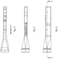
- the adapter tip 200 comprises a housing 204 having a mating interface 206 on its proximal end 208 configured to mechanically engage with the connector adapter 100 and a connection mechanism 210 on its distal end 212 to releasably attach to an inspection microscope 201.
- the housing 204 defines a light-relaying channel 216 (see Fig. 8 ) between its proximal end 208 and its distal end 212 to relay the object beam from the optical-fiber endface 104 to the objective lens 226 of the inspection microscope 201.
- the mating interface 206 has outer dimensions that are substantially complementary to inner dimensions of a connector-receiving channel 116 (see Fig. 1 ) of the connector adapter 100 so that it easily inserts into the connector adapter 100 in close proximity with the optical-fiber endface 104 to be inspected, and this without direct contact with the optical-fiber endface 104. Alignment of adapter tip 200 to the optical-fiber connector 102 is at least partly achieved by the small mechanical play of the mating interface 206 within the connector adapter 100.
- connection mechanism 210 is a screw-threaded mechanism including threads (not shown) on the external surface of the adapter tip 100.
- the inspection microscope 201 has a corresponding connection mechanism (not shown) comprising a swiveled threaded ring.
- the adapter tip 200 is attached to the inspection microscope 201 by screwing the threaded ring on the threads of the connection mechanism 210.
- other solid and releasable connection mechanisms such as a bayonet connector for example may be used instead.
- the adapter tip 200 comprises a relay optical system 220 disposed within the light relaying channel 216 defined in the housing 204.
- the relay optical system 220 comprises a first relay lens 222, a second relay lens 224 and a Rhomboid prism 228.
- the first relay lens 222 is disposed at the proximal end 208 of the adapter tip 200 so as to be adjacent to but in no direct contact with the inspected optical-fiber endface 104 when the adapter tip 200 is inserted in a connector adapter 100, in order to directly receive the object beam reflected from the optical-fiber endface 104 (through reflection of the illumination light).
- the first relay lens 222 is positioned as close as possible to the proximal end 208 of the adapter tip 200 so as to collect as much of the divergent object beam as possible, although not all light from the light beam reflected on the optical-fiber enface can realistically be collected.
- the first relay lens 222 is therefore positioned within the connector adapter 100 when the mating interface 206 of the adapter tip 100 is inserted into the connector-receiving channel 116 of the connector adapter 100.
- the second relay lens 224 is disposed in the light relaying channel 216, spaced apart from the first relay lens 222.
- the Rhomboid prism 228 is disposed between the first relay lens 222 and the second relay lens 224 in order to laterally shift the light beam reflected from the optical-fiber endfaces and relayed by the first relay lens 222, towards a lens axis of the second relay lens 224.
- Rhomboid prisms are known in the art and used to displace a laser beam typically without changing the image orientation. Rhomboid prisms use total internal reflection on two faces typically disposed at 45 degrees relative to the central axis of the incident beam. In the embodiment of Figs. 2 to 9 , the Rhomboid prism 228 shifts the incident beam without angular deviation or orientation change; and the Rhomboid prism 228 shifts the optical centerline of the incident beam by the prism length "L" without inverting the image.
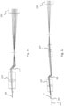
- Fig. 10 illustrates a hypothetical relay optical system as could be needed to image the optical fiber endface 104 without the Rhomboid prism 228.
- the second lens 224 is positioned laterally offset from the first lens 222 and the objective lens 226 is positioned laterally offset from the second lens 224, further offset from the first lens 222.
- the first lens 222 it may also be positioned laterally offset from the center of the optical-fiber endface, or not.
- Such a design in "stairs" can be problematic because the adapter tip is no linear, which can make the tip interfere with adjacent optical-fiber connectors in a tested patch panel.
- the object 804 to be imaged i.e., the optical-fiber endface 104, lies in a real object plane 802, to within a focusing range of the inspection microscope 201.
- the relay optical system reproduces the real object 804 that lies in the real object plane 802 on an intermediate image plane 806 that may be slightly tilted relative to the real object plane 802 towards a plane orthogonal to the optical-fiber axis 800, so as to reduce the angle between the normal n of the intermediate image plane 802 and the optical-fiber axis 800 of the connector 102.
- the lens axis of the first relay lens 222 can be made slightly offset relative to the optical-fiber endface 104.
- the lens axis of the second relay lens 224 is also slightly offset relative to the center of relay lens 222 so that it is not aligned therewith.
- the normal n to the inspected optical-fiber endface 104, and hence of the real object plane 802 forms an 8° angle relative to the imaging and illumination axis of the inspection microscope 201.
- the objective lens 226 is disposed such that the intermediate image plane 806 substantially lies on the original object plane 816 of the inspection microscope 201 (without the adapter tip 200) to within its focusing range.
- the lens axis 814 of the objective lens 226 (also referred to herein as the imaging and illumination axis 814 of the inspection microscope 201) is also slightly offset along the y-axis relative to the lens axis of the second relay lens 224.
- the relay optical system 220 of Fig. 9 is the same as that shown and described with reference to Fig. 10 , except for the added Rhomboid prism 228 along the optical path, which laterally shifts the object beam 126 in the opposite direction of the offsets, i.e. towards a direction opposite to the rejection y of the normal n to the optical-fiber endface on the optical-fiber axis of the connector, in order to make the tip more linear and cross-sectionally compact so that is does not mechanically interfere with adjacent optical-fiber connectors in a patch panel.
- the Rhomboid prism 228 does not substantially impact the quality of the image captured by the inspection microscope.
- the Rhomboid prism 228 may optionally be positioned so that its input and output faces are not perfectly perpendicular to the centerline of the object beam so as to avoid parasite reflections toward the image sensor of the inspection microscope 201.
- the first relay lens 222, the Rhomboid prism 228 and the second relay lens 224 cooperate to together propagate the object beam 126 close to the optical-fiber axis 800 of the connector 102, in a cross-sectionally compact optical design.
- the first relay lens 222, the second relay lens 224, the Rhomboid prism 228 and the objective lens 226 define an optical system.
- the optical axes of both relay lenses 222, 224 are parallel to the optical-fiber axis 800, and therefore not normal to the inspected endface (there is an 8° angle between the normal n to the optical-fiber endface and the optical-fiber axis).
- the optical axis of the objective lens 226 is also made parallel to the optical axes of both relay lenses 222, 224 and the optical-fiber axis 800.
- the lenses are therefore disposed such that their optical axes are all parallel (including the objective lens 226), which makes the adapter tip 200 much easier to manufacture with good precision in the relative orientations of the relay lenses 222, 224 and the objective lens 226.
- the centerline of the object beam 126 is deviated by the first relay lens 222 and then further deviated by the second relay lens 224.
- relay lenses 222 and 224 may optionally consist of compound lenses in order to provide low distortion and good off-axis performance.
- relay lenses 222 and 224 may each comprise an achromatic triplet lens made of a symmetric double convex lens element cemented between two identical negative meniscus lens elements having a refractive index higher than that of the convex lens element.
- the achromatic triplet lenses may be optimized for minimizing off-axis aberrations when employed with an infinite conjugate ratio, i.e., when focusing on infinity an object point placed at focal distance.
- relay lenses 222 and 224 may consist of a Hasting triplet lens.
- Hasting triplet lenses are optimized for an infinite conjugate ratio.
- Relay lens 222 is then disposed such that its focal point lies nearly on the real object plane 802.
- relay lens 224 is disposed relative to the objective lens 226 such that its focal point lies nearly on the original object plane 816 defined by the inspection microscope 201.
- triplet lenses are optional and that simple lenses may also be found perfectly suitable for some embodiments, depending on the specific design and practical application.
- adapter tip 200 of the embodiment of Figs. 2 to 9 is designed for inspecting MDC-APC connectors
- other embodiments may include adapter tips designed for inspecting other types of connectors, including some future connectors not even yet commercially available.
- the relay lenses may be more simple or more complex, be made aspheric or include additional optical components as may be rendered necessary by the specific design or practical application.
- Other components may also be included along the optical axis within the adapter tip, e.g., to improve its optical performance, such as, e.g., aberration compensation element(s).
- relay lenses may vary. Adapter tip configurations including zero, one or more relay lenses are all envisaged.
- Fig. 11 shows an optical configuration in accordance with an embodiment in which the adapter tip comprises a single relay lens 222' and a Rhomboid prism 228.
- the relay lens 222' may consists, e.g., of a Hasting triplet lens and the lens parameters such as the focal length may need to vary from those of Fig. 9 .
- Fig. 12 shows an optical configuration in accordance with such another embodiment wherein respective optical axes of relay lenses 222", 224" are not parallel to the optical-fiber axis 800 of the optical-fiber connector 102.
- the lens axis of the objective lens 226 is parallel to the optical-fiber axis 800 but in other embodiments, it could be made unparallel as well.
- the mechanical configuration of the adapter tip may need to be adapted to implement such optical configuration.
- the Rhomboid prism 228 is disposed between the first relay lens 222 and the second relay lens 224, the position of the Rhomboid prism 228 may vary.
- the Rhomboid prism 228 may rather be positioned close to the proximal end 208 of the adapter tip to relay the divergent object beam to the first relay lens 222, i.e., between the inspected optical-fiber endface 104 and the first relay lens 222.
- the Rhomboid prism 228 may rather be positioned between the second relay lens 224 and the objective lens 226 of the inspection microscope.
- Fig. 15 illustrates an inspection microscope system 900 which employs an adapter tip 200 as described herein.
- the inspection microscope system 900 comprises a combination of an inspection microscope 902 and an adapter tip 200.
- the inspection microscope system of Fig. 15 is illustrated with the adapter tip 200 of Figs. 2 to 9 but it will be understood that it is designed for use with interchangeable tips and that the adapter tip can be replaced with any other embodiment of adapter tips described herein.
- the inspection microscope 902 at least contains an optical-fiber endface imaging assembly 904 comprising an illumination source 906, an objective lens 226, an image sensor 908 and a beam splitter 910.
- the illumination source 906 illuminates the optical-fiber endface 104 and can be embodied in a lightemitting diode (LED) typically emitting in the blue wavelength region.
- the objective lens 226 directs the illumination light on the optical-fiber endface 104 to be imaged and collects light returned from the optical-fiber endface 104 through reflection of the illumination light in order to image the optical-fiber endface 104 on the image sensor 908 positioned on an image plane 912.
- the image sensor 908 may be embodied in a complementary metal-oxide-semiconductor (CMOS) sensor or a charge-coupled device (CCD), for instance.
- CMOS complementary metal-oxide-semiconductor
- CCD charge-coupled device
- the beam splitter 910 e.g., a 50/50 beam splitter, is located between the objective lens 226 and the image sensor 908. It both directs the illumination light towards the objective lens 226 for illuminating the optical-fiber endface 104 and propagates the returned object beam 126 from the objective lens 226 to the image sensor 908.
- optical element(s) may be included in the inspection microscope 902 such as, e.g., aberration compensation optical element(s).
- the orientation of the Rhomboid prism 228 may vary relative to the centerline 1000 of the object beam.
- the reflection faces 1006, 1008 of the Rhomboid prism are disposed at 45 degrees relative to the input and output faces 1002, 1004.
- the Rhomboid prism can be oriented so that its input and output faces 1002, 1004 are perpendicular to the centerline 1000 or, as shown in Fig. 16B , it can be slightly tilted so that the centerline 1000 is not perpendicular to the input and output faces 1002, 1004.
- opposite reflection faces of the Rhomboid prism can even be made non-parallel, so as to angularly deviate the incident beam in addition to the shift.
- Fig. 17 illustrates an example application of such an irregular Rhomboid prism having non-parallel opposite reflection faces.
- the relay optical system of the adapter tip has no relay lens and comprises only a Rhomboid prism.
- the Rhomboid prism is used to angularly deviate the centerline of the object beam towards the optical-fiber axis 800 so as to relay the light beam towards the objective lens 226 of the inspection microscope.
- an angled-polished optical-fiber connector 102 can be inspected with a straight adapter tip wherein the lens axis of the objective lens 226 can be made parallel to the optical-fiber axis 800.
- the reflection faces of the Rhomboid prism are slightly non-parallel with an angle of a few degrees with respect to one another.
Landscapes
- Physics & Mathematics (AREA)
- General Physics & Mathematics (AREA)
- Optics & Photonics (AREA)
- Chemical & Material Sciences (AREA)
- Analytical Chemistry (AREA)
- Astronomy & Astrophysics (AREA)
- Microscoopes, Condenser (AREA)
Claims (13)
- Adapterspitze (200), die mit einem Inspektions-Mikroskop (201) für eine Lichtwellenleiter-Verbinderendfläche zum Abbilden einer Lichtwellenleiter-Endfläche eines winkelpolierten Lichtwellenleiter-Verbinders zu verwenden ist, der innerhalb eines Verbinderadapters eingelassen ist, wobei die Adapterspitze umfasst:ein Gehäuse (204) mit einer passenden Schnittstelle (206), die konfiguriert ist, um mechanisch in den Verbinderradapter zum Kontrollieren der Lichtwellenleiter-Endfläche des winkelpolierten Lichtwellenleiter-Verbinders einzugreifen, der in den Verbinderadapter eingelassen ist, wobei die Lichtwellenleiter-Endfläche daher eine winkelpolierte Lichtwellenleiter-Endfläche ist, undein optisches Relaissystem (220), das in dem Gehäuse angeordnet ist,wobei das optische Relaissystem den Lichtstrahl zu einer optischen Achse des Inspektions-Mikroskops für die Lichtwellenleiter-Verbinderendfläche weiterleitet, wobei die Adapterspitze dadurch gekennzeichnet ist, dass das optische Relaissystem ein Rhomboidprisma (228) umfasst, wobei das Rhomboidprisma angeordnet ist, um das von der Lichtwellenleiter-Endfläche während der Inspektion reflektierte Licht zu empfangen und den von der winkelpolierten Lichtwellenleiter-Endflächen reflektierten Lichtstrahl seitlich zu verschieben.
- Adapterspitze nach Anspruch 1, wobei das Rhomboidprisma den von der winkelpolierten Lichtwellenleiter-Endfläche reflektierten Lichtstrahl seitlich in eine Richtung verschiebt, die der Vektorabweisung der Senkrechten zur Lichtwellenleiter-Endfläche auf der Lichtwellenleiter-Achse des Verbinders entgegengesetzt ist.
- Adapterspitze nach Anspruch 1 oder 2, wobei das optische Relaissystem ferner mindestens eine erste Relaislinse und eine zweite Relaislinse umfasst, wobei die erste Relaislinse in der Nähe der Lichtwellenleiter-Endfläche angeordnet ist, um Licht zu empfangen, das von der Lichtwellenleiter-Endfläche während der Inspektion reflektiert wird, und die zweite Relaislinse von der ersten Relaislinse im Abstand angeordnet ist, um den Lichtstrahl zur optischen Achse des Inspektions-Mikroskops für die Lichtwellenleiter-Verbinderendfläche weiterzuleiten.
- Adapterspitze nach Anspruch 3, wobei die erste Relaislinse angeordnet ist, um während der Inspektion das von der Lichtwellenleiter-Endfläche reflektierte Licht direkt zu empfangen, und das Rhomboidprisma zwischen der ersten Relaislinse und der zweiten Relaislinse angeordnet ist, um den von der Lichtwellenleiter-Endfläche reflektierten und von der ersten Relaislinse weitergeleiteten Lichtstrahl seitlich in Richtung der Linsenachse der zweiten Relaislinse zu verschieben.
- Adapterspitze nach Anspruch 3 oder 4, wobei eine Linsenachse der ersten Relaislinse auf eine Mitte der Lichtwellenleiter-Endfläche ausgerichtet ist.
- Adapterspitze nach Anspruch 3 oder 4, wobei eine Linsenachse der ersten Relaislinse gegenüber einer Mittellinie des Objektstrahls in eine Richtung versetzt ist, die der Vektorabweisung der Senkrechten auf die Lichtwellenleiter-Endfläche auf der Lichtwellenleiter-Achse des Verbinders entspricht, um den von der Lichtwellenleiter-Endfläche reflektierten Lichtstrahl in Richtung der Lichtwellenleiter-Achse des Verbinders abzulenken.
- Adapterspitze nach Anspruch 6, wobei die Linsenachse der zweiten Relaislinse relativ zu einer Mitte der Lichtwellenleiter-Endfläche in eine Richtung versetzt ist, die der Vektorabweisung der Senkrechten zur Lichtwellenleiter-Endfläche auf der Lichtwellenleiter-Achse des Verbinders entgegengesetzt ist, um den durch das Rhomboidprisma seitlich verschobenen Lichtstrahl zu empfangen.
- Adapterspitze nach Anspruch 6 oder 7, wobei eine Linsenachse der ersten Relaislinse und die Linsenachse der zweiten Relaislinse beide parallel zu einer Lichtwellenleiter-Achse des Verbinders sind.
- Adapterspitze nach einem der Ansprüche 1 bis 8, wobei die Adapterspitze während der Inspektion Beleuchtungslicht von dem Inspektions-Mikroskop für eine Lichtwellenleiter-Verbinderendfläche empfängt, um die Lichtwellenleiter-Endfläche abzubilden, und wobei das optische Relaissystem so konfiguriert ist, dass es das Beleuchtungslicht auf die Lichtwellenleiter-Endfläche umlenkt.
- Inspektions-Mikroskopsystem (202) für eine Lichtwellenleiter-Verbinderendfläche zum Abbilden einer Lichtwellenleiter-Endfläche eines winkelpolierten Lichtwellenleiter-Verbinders, der in einen Verbinderadapter eingelassen ist, wobei das Mikroskopsystem umfasst:ein Inspektions-Mikroskop (201) für eine Lichtwellenleiter-Verbinderendfläche, umfassend eine Objektivlinse (226); unddie Adapterspitze (200) nach einem der Ansprüche 1 bis 9.
- Inspektions-Mikroskopsystem für eine Lichtwellenleiter-Verbinderendfläche nach Anspruch 10, wobei die Linsenachse der Objektivlinse während der Inspektion parallel zu der Lichtwellenleiter-Achse verläuft.
- Inspektions-Mikroskopsystem für eine Lichtwellenleiter-Verbinderendfläche nach Anspruch 11, wobei die Adapterspitze eine Adapterspitze nach einem der Ansprüche 3 bis 8 ist und eine Linsenachse der Objektivlinse des Inspektions-Mikroskops für eine Lichtwellenleiter-Verbinderendfläche während der Inspektion relativ zur Linsenachse der zweiten Relaislinse versetzt ist.
- Inspektions-Mikroskopsystem für eine Lichtwellenleiter-Verbinderendfläche nach Anspruch 10, wobei die Adapterspitze eine Adapterspitze nach einem der Ansprüche 3 bis 8 ist, und das optische Relaissystem der Adapterspitze eine Zwischenbildebene zwischen der zweiten Relaislinse und der Objektivlinse des Inspektions-Mikroskops für eine Lichtwellenleiter-Verbinderendfläche erzeugt.
Applications Claiming Priority (1)
| Application Number | Priority Date | Filing Date | Title |
|---|---|---|---|
| US202063059209P | 2020-07-31 | 2020-07-31 |
Publications (2)
| Publication Number | Publication Date |
|---|---|
| EP3945352A1 EP3945352A1 (de) | 2022-02-02 |
| EP3945352B1 true EP3945352B1 (de) | 2023-11-01 |
Family
ID=77103899
Family Applications (1)
| Application Number | Title | Priority Date | Filing Date |
|---|---|---|---|
| EP21188072.9A Active EP3945352B1 (de) | 2020-07-31 | 2021-07-27 | Adapterspitze und mikroskopsystem zur inspektion von faseroptischen steckerendflächen |
Country Status (3)
| Country | Link |
|---|---|
| US (1) | US11644625B2 (de) |
| EP (1) | EP3945352B1 (de) |
| CA (1) | CA3125161A1 (de) |
Families Citing this family (8)
| Publication number | Priority date | Publication date | Assignee | Title |
|---|---|---|---|---|
| US11489989B2 (en) * | 2020-04-27 | 2022-11-01 | Viavi Solutions Inc. | System for illuminating and viewing recessed angled surfaces |
| CA3125161A1 (en) * | 2020-07-31 | 2022-01-31 | Exfo Inc. | Adapter tip and microscope system for inspection of fiber-optic connector endfaces |
| US12429653B2 (en) * | 2022-05-11 | 2025-09-30 | Exfo Inc. | Adapter tip and microscope system for inspecting duplex fiber-optic connector endfaces |
| US12498317B1 (en) * | 2023-03-28 | 2025-12-16 | J.A. Woollam Co., Inc. | Sample alignment system in reflectometers, ellipsometers, spectrophotometers and the like |
| US12546681B2 (en) * | 2023-06-02 | 2026-02-10 | Viavi Solutions Inc. | Changeable tip for optical fiber inspection device |
| US20250044126A1 (en) * | 2023-07-31 | 2025-02-06 | Viavi Solutions Inc. | Tip for optical fiber inspection device |
| EP4644959A1 (de) | 2024-04-30 | 2025-11-05 | EXFO Inc. | Faseroptisches endflächeninspektionsmikroskop, das native für abgewinkelte polierte verbinder angepasst ist |
| US20250383259A1 (en) * | 2024-06-14 | 2025-12-18 | Exfo Inc. | Optical fiber endface inspection microscope configurable for inspection of angled- and non-angled-polished connectors |
Family Cites Families (12)
| Publication number | Priority date | Publication date | Assignee | Title |
|---|---|---|---|---|
| FR2337326A1 (fr) | 1975-12-29 | 1977-07-29 | Realisations Electronique Et | Appareil d'observation et de visee, notamment sur vehicule |
| US6215924B1 (en) | 1998-08-06 | 2001-04-10 | Optical Coating Laboratory, Inc. | Optical coupler device for dense wavelength division multiplexing |
| US6751017B2 (en) | 2002-03-19 | 2004-06-15 | Westover Scientific, Inc. | Microscope for backplane ribbon fiber analysis |
| TW200718976A (en) * | 2005-11-02 | 2007-05-16 | Asia Optical Co Inc | Zoom telescope |
| US7356236B1 (en) | 2006-12-14 | 2008-04-08 | Lightel Technologies Inc. | Field-use apparatus for inspecting and cleaning fiber optic connectors |
| US8237935B2 (en) * | 2007-10-23 | 2012-08-07 | Gii Acquisition, Llc | Method and system for automatically inspecting parts and for automatically generating calibration data for use in inspecting parts |
| US8164744B2 (en) | 2008-10-30 | 2012-04-24 | Adc Telecommunications, Inc. | Inspection tip for a fiber optic inspection probe |
| WO2013097041A1 (en) | 2011-12-28 | 2013-07-04 | Exfo Inc. | Portable digital holographic probe for the inspection of optical fiber connectors, and inspection system and method for the same |
| US8976345B2 (en) | 2013-06-04 | 2015-03-10 | Lightel Technologies, Inc. | Fitting tip with relay lens for fiber-optic connector endface inspector |
| EP3096124B1 (de) | 2015-05-21 | 2018-09-05 | EXFO Inc. | Adapterspitze und mikroskopsystem zur inspektion einer faseroptischen steckerendfläche |
| US10175142B2 (en) * | 2015-07-02 | 2019-01-08 | Exfo Inc. | Multiple-fiber connector inspection |
| CA3125161A1 (en) * | 2020-07-31 | 2022-01-31 | Exfo Inc. | Adapter tip and microscope system for inspection of fiber-optic connector endfaces |
-
2021
- 2021-07-20 CA CA3125161A patent/CA3125161A1/en active Pending
- 2021-07-27 EP EP21188072.9A patent/EP3945352B1/de active Active
- 2021-07-27 US US17/443,496 patent/US11644625B2/en active Active
Also Published As
| Publication number | Publication date |
|---|---|
| CA3125161A1 (en) | 2022-01-31 |
| US20220035104A1 (en) | 2022-02-03 |
| EP3945352A1 (de) | 2022-02-02 |
| US11644625B2 (en) | 2023-05-09 |
Similar Documents
| Publication | Publication Date | Title |
|---|---|---|
| EP3945352B1 (de) | Adapterspitze und mikroskopsystem zur inspektion von faseroptischen steckerendflächen | |
| EP3096124B1 (de) | Adapterspitze und mikroskopsystem zur inspektion einer faseroptischen steckerendfläche | |
| US9915790B2 (en) | Fiber inspection microscope and power measurement system, fiber inspection tip and method using same | |
| US6793399B1 (en) | System and method for optical port inspection for telecommunication systems and devices | |
| US9841579B2 (en) | Multiple-fiber connector inspection | |
| CA2751329C (en) | Fiber optic jack and connector | |
| US11274991B2 (en) | Fiber optic ferrule inspection tool | |
| US12429653B2 (en) | Adapter tip and microscope system for inspecting duplex fiber-optic connector endfaces | |
| US8976345B2 (en) | Fitting tip with relay lens for fiber-optic connector endface inspector | |
| US20130321906A1 (en) | Annulus to create distinct illumination and imaging apertures for an imaging system | |
| US10900866B2 (en) | Optical fiber endface inspection with optical power measurement | |
| US12455417B2 (en) | MPO adapter for APC connector inspection | |
| US12050149B2 (en) | Optical fiber endface inspection microscope having a swappable optical head | |
| US20210080658A1 (en) | Fiber optic connector dust cap and related method | |
| US20240255713A1 (en) | Adapter tip and microscope system for inspecting apc trans-duplex fiber-optic connectors | |
| US10627310B2 (en) | Imaging system for multi-fiber connector inspection | |
| US20250076625A1 (en) | Adapter tip and microscope system for inspecting angled-polished optical-fiber connectors | |
| EP4644959A1 (de) | Faseroptisches endflächeninspektionsmikroskop, das native für abgewinkelte polierte verbinder angepasst ist | |
| US20210215572A1 (en) | Inspection Tip Having a Self-Adjusting Prism for an Optical Fiber and Method of Use |
Legal Events
| Date | Code | Title | Description |
|---|---|---|---|
| PUAI | Public reference made under article 153(3) epc to a published international application that has entered the european phase |
Free format text: ORIGINAL CODE: 0009012 |
|
| STAA | Information on the status of an ep patent application or granted ep patent |
Free format text: STATUS: THE APPLICATION HAS BEEN PUBLISHED |
|
| AK | Designated contracting states |
Kind code of ref document: A1 Designated state(s): AL AT BE BG CH CY CZ DE DK EE ES FI FR GB GR HR HU IE IS IT LI LT LU LV MC MK MT NL NO PL PT RO RS SE SI SK SM TR |
|
| STAA | Information on the status of an ep patent application or granted ep patent |
Free format text: STATUS: REQUEST FOR EXAMINATION WAS MADE |
|
| 17P | Request for examination filed |
Effective date: 20220629 |
|
| RBV | Designated contracting states (corrected) |
Designated state(s): AL AT BE BG CH CY CZ DE DK EE ES FI FR GB GR HR HU IE IS IT LI LT LU LV MC MK MT NL NO PL PT RO RS SE SI SK SM TR |
|
| GRAP | Despatch of communication of intention to grant a patent |
Free format text: ORIGINAL CODE: EPIDOSNIGR1 |
|
| STAA | Information on the status of an ep patent application or granted ep patent |
Free format text: STATUS: GRANT OF PATENT IS INTENDED |
|
| INTG | Intention to grant announced |
Effective date: 20230512 |
|
| GRAS | Grant fee paid |
Free format text: ORIGINAL CODE: EPIDOSNIGR3 |
|
| GRAA | (expected) grant |
Free format text: ORIGINAL CODE: 0009210 |
|
| STAA | Information on the status of an ep patent application or granted ep patent |
Free format text: STATUS: THE PATENT HAS BEEN GRANTED |
|
| AK | Designated contracting states |
Kind code of ref document: B1 Designated state(s): AL AT BE BG CH CY CZ DE DK EE ES FI FR GB GR HR HU IE IS IT LI LT LU LV MC MK MT NL NO PL PT RO RS SE SI SK SM TR |
|
| P01 | Opt-out of the competence of the unified patent court (upc) registered |
Effective date: 20230921 |
|
| REG | Reference to a national code |
Ref country code: GB Ref legal event code: FG4D |
|
| REG | Reference to a national code |
Ref country code: CH Ref legal event code: EP |
|
| REG | Reference to a national code |
Ref country code: IE Ref legal event code: FG4D |
|
| REG | Reference to a national code |
Ref country code: DE Ref legal event code: R096 Ref document number: 602021006360 Country of ref document: DE |
|
| REG | Reference to a national code |
Ref country code: LT Ref legal event code: MG9D |
|
| REG | Reference to a national code |
Ref country code: NL Ref legal event code: MP Effective date: 20231101 |
|
| PG25 | Lapsed in a contracting state [announced via postgrant information from national office to epo] |
Ref country code: GR Free format text: LAPSE BECAUSE OF FAILURE TO SUBMIT A TRANSLATION OF THE DESCRIPTION OR TO PAY THE FEE WITHIN THE PRESCRIBED TIME-LIMIT Effective date: 20240202 |
|
| PG25 | Lapsed in a contracting state [announced via postgrant information from national office to epo] |
Ref country code: IS Free format text: LAPSE BECAUSE OF FAILURE TO SUBMIT A TRANSLATION OF THE DESCRIPTION OR TO PAY THE FEE WITHIN THE PRESCRIBED TIME-LIMIT Effective date: 20240301 |
|
| PG25 | Lapsed in a contracting state [announced via postgrant information from national office to epo] |
Ref country code: LT Free format text: LAPSE BECAUSE OF FAILURE TO SUBMIT A TRANSLATION OF THE DESCRIPTION OR TO PAY THE FEE WITHIN THE PRESCRIBED TIME-LIMIT Effective date: 20231101 |
|
| REG | Reference to a national code |
Ref country code: AT Ref legal event code: MK05 Ref document number: 1627864 Country of ref document: AT Kind code of ref document: T Effective date: 20231101 |
|
| PG25 | Lapsed in a contracting state [announced via postgrant information from national office to epo] |
Ref country code: NL Free format text: LAPSE BECAUSE OF FAILURE TO SUBMIT A TRANSLATION OF THE DESCRIPTION OR TO PAY THE FEE WITHIN THE PRESCRIBED TIME-LIMIT Effective date: 20231101 |
|
| PG25 | Lapsed in a contracting state [announced via postgrant information from national office to epo] |
Ref country code: AT Free format text: LAPSE BECAUSE OF FAILURE TO SUBMIT A TRANSLATION OF THE DESCRIPTION OR TO PAY THE FEE WITHIN THE PRESCRIBED TIME-LIMIT Effective date: 20231101 |
|
| PG25 | Lapsed in a contracting state [announced via postgrant information from national office to epo] |
Ref country code: ES Free format text: LAPSE BECAUSE OF FAILURE TO SUBMIT A TRANSLATION OF THE DESCRIPTION OR TO PAY THE FEE WITHIN THE PRESCRIBED TIME-LIMIT Effective date: 20231101 |
|
| PG25 | Lapsed in a contracting state [announced via postgrant information from national office to epo] |
Ref country code: NL Free format text: LAPSE BECAUSE OF FAILURE TO SUBMIT A TRANSLATION OF THE DESCRIPTION OR TO PAY THE FEE WITHIN THE PRESCRIBED TIME-LIMIT Effective date: 20231101 Ref country code: LT Free format text: LAPSE BECAUSE OF FAILURE TO SUBMIT A TRANSLATION OF THE DESCRIPTION OR TO PAY THE FEE WITHIN THE PRESCRIBED TIME-LIMIT Effective date: 20231101 Ref country code: IS Free format text: LAPSE BECAUSE OF FAILURE TO SUBMIT A TRANSLATION OF THE DESCRIPTION OR TO PAY THE FEE WITHIN THE PRESCRIBED TIME-LIMIT Effective date: 20240301 Ref country code: GR Free format text: LAPSE BECAUSE OF FAILURE TO SUBMIT A TRANSLATION OF THE DESCRIPTION OR TO PAY THE FEE WITHIN THE PRESCRIBED TIME-LIMIT Effective date: 20240202 Ref country code: ES Free format text: LAPSE BECAUSE OF FAILURE TO SUBMIT A TRANSLATION OF THE DESCRIPTION OR TO PAY THE FEE WITHIN THE PRESCRIBED TIME-LIMIT Effective date: 20231101 Ref country code: BG Free format text: LAPSE BECAUSE OF FAILURE TO SUBMIT A TRANSLATION OF THE DESCRIPTION OR TO PAY THE FEE WITHIN THE PRESCRIBED TIME-LIMIT Effective date: 20240201 Ref country code: AT Free format text: LAPSE BECAUSE OF FAILURE TO SUBMIT A TRANSLATION OF THE DESCRIPTION OR TO PAY THE FEE WITHIN THE PRESCRIBED TIME-LIMIT Effective date: 20231101 Ref country code: PT Free format text: LAPSE BECAUSE OF FAILURE TO SUBMIT A TRANSLATION OF THE DESCRIPTION OR TO PAY THE FEE WITHIN THE PRESCRIBED TIME-LIMIT Effective date: 20240301 |
|
| PG25 | Lapsed in a contracting state [announced via postgrant information from national office to epo] |
Ref country code: SE Free format text: LAPSE BECAUSE OF FAILURE TO SUBMIT A TRANSLATION OF THE DESCRIPTION OR TO PAY THE FEE WITHIN THE PRESCRIBED TIME-LIMIT Effective date: 20231101 Ref country code: RS Free format text: LAPSE BECAUSE OF FAILURE TO SUBMIT A TRANSLATION OF THE DESCRIPTION OR TO PAY THE FEE WITHIN THE PRESCRIBED TIME-LIMIT Effective date: 20231101 Ref country code: PL Free format text: LAPSE BECAUSE OF FAILURE TO SUBMIT A TRANSLATION OF THE DESCRIPTION OR TO PAY THE FEE WITHIN THE PRESCRIBED TIME-LIMIT Effective date: 20231101 Ref country code: NO Free format text: LAPSE BECAUSE OF FAILURE TO SUBMIT A TRANSLATION OF THE DESCRIPTION OR TO PAY THE FEE WITHIN THE PRESCRIBED TIME-LIMIT Effective date: 20240201 Ref country code: LV Free format text: LAPSE BECAUSE OF FAILURE TO SUBMIT A TRANSLATION OF THE DESCRIPTION OR TO PAY THE FEE WITHIN THE PRESCRIBED TIME-LIMIT Effective date: 20231101 Ref country code: HR Free format text: LAPSE BECAUSE OF FAILURE TO SUBMIT A TRANSLATION OF THE DESCRIPTION OR TO PAY THE FEE WITHIN THE PRESCRIBED TIME-LIMIT Effective date: 20231101 |
|
| PG25 | Lapsed in a contracting state [announced via postgrant information from national office to epo] |
Ref country code: DK Free format text: LAPSE BECAUSE OF FAILURE TO SUBMIT A TRANSLATION OF THE DESCRIPTION OR TO PAY THE FEE WITHIN THE PRESCRIBED TIME-LIMIT Effective date: 20231101 |
|
| PG25 | Lapsed in a contracting state [announced via postgrant information from national office to epo] |
Ref country code: CZ Free format text: LAPSE BECAUSE OF FAILURE TO SUBMIT A TRANSLATION OF THE DESCRIPTION OR TO PAY THE FEE WITHIN THE PRESCRIBED TIME-LIMIT Effective date: 20231101 |
|
| PG25 | Lapsed in a contracting state [announced via postgrant information from national office to epo] |
Ref country code: SK Free format text: LAPSE BECAUSE OF FAILURE TO SUBMIT A TRANSLATION OF THE DESCRIPTION OR TO PAY THE FEE WITHIN THE PRESCRIBED TIME-LIMIT Effective date: 20231101 |
|
| PG25 | Lapsed in a contracting state [announced via postgrant information from national office to epo] |
Ref country code: SM Free format text: LAPSE BECAUSE OF FAILURE TO SUBMIT A TRANSLATION OF THE DESCRIPTION OR TO PAY THE FEE WITHIN THE PRESCRIBED TIME-LIMIT Effective date: 20231101 Ref country code: SK Free format text: LAPSE BECAUSE OF FAILURE TO SUBMIT A TRANSLATION OF THE DESCRIPTION OR TO PAY THE FEE WITHIN THE PRESCRIBED TIME-LIMIT Effective date: 20231101 Ref country code: IT Free format text: LAPSE BECAUSE OF FAILURE TO SUBMIT A TRANSLATION OF THE DESCRIPTION OR TO PAY THE FEE WITHIN THE PRESCRIBED TIME-LIMIT Effective date: 20231101 Ref country code: EE Free format text: LAPSE BECAUSE OF FAILURE TO SUBMIT A TRANSLATION OF THE DESCRIPTION OR TO PAY THE FEE WITHIN THE PRESCRIBED TIME-LIMIT Effective date: 20231101 Ref country code: DK Free format text: LAPSE BECAUSE OF FAILURE TO SUBMIT A TRANSLATION OF THE DESCRIPTION OR TO PAY THE FEE WITHIN THE PRESCRIBED TIME-LIMIT Effective date: 20231101 Ref country code: CZ Free format text: LAPSE BECAUSE OF FAILURE TO SUBMIT A TRANSLATION OF THE DESCRIPTION OR TO PAY THE FEE WITHIN THE PRESCRIBED TIME-LIMIT Effective date: 20231101 |
|
| REG | Reference to a national code |
Ref country code: DE Ref legal event code: R097 Ref document number: 602021006360 Country of ref document: DE |
|
| PLBE | No opposition filed within time limit |
Free format text: ORIGINAL CODE: 0009261 |
|
| STAA | Information on the status of an ep patent application or granted ep patent |
Free format text: STATUS: NO OPPOSITION FILED WITHIN TIME LIMIT |
|
| 26N | No opposition filed |
Effective date: 20240802 |
|
| PG25 | Lapsed in a contracting state [announced via postgrant information from national office to epo] |
Ref country code: SI Free format text: LAPSE BECAUSE OF FAILURE TO SUBMIT A TRANSLATION OF THE DESCRIPTION OR TO PAY THE FEE WITHIN THE PRESCRIBED TIME-LIMIT Effective date: 20231101 |
|
| PG25 | Lapsed in a contracting state [announced via postgrant information from national office to epo] |
Ref country code: SI Free format text: LAPSE BECAUSE OF FAILURE TO SUBMIT A TRANSLATION OF THE DESCRIPTION OR TO PAY THE FEE WITHIN THE PRESCRIBED TIME-LIMIT Effective date: 20231101 |
|
| PG25 | Lapsed in a contracting state [announced via postgrant information from national office to epo] |
Ref country code: MC Free format text: LAPSE BECAUSE OF FAILURE TO SUBMIT A TRANSLATION OF THE DESCRIPTION OR TO PAY THE FEE WITHIN THE PRESCRIBED TIME-LIMIT Effective date: 20231101 |
|
| REG | Reference to a national code |
Ref country code: CH Ref legal event code: PL |
|
| PG25 | Lapsed in a contracting state [announced via postgrant information from national office to epo] |
Ref country code: LU Free format text: LAPSE BECAUSE OF NON-PAYMENT OF DUE FEES Effective date: 20240727 |
|
| PG25 | Lapsed in a contracting state [announced via postgrant information from national office to epo] |
Ref country code: LU Free format text: LAPSE BECAUSE OF NON-PAYMENT OF DUE FEES Effective date: 20240727 |
|
| PG25 | Lapsed in a contracting state [announced via postgrant information from national office to epo] |
Ref country code: BE Free format text: LAPSE BECAUSE OF NON-PAYMENT OF DUE FEES Effective date: 20240731 Ref country code: CH Free format text: LAPSE BECAUSE OF NON-PAYMENT OF DUE FEES Effective date: 20240731 |
|
| REG | Reference to a national code |
Ref country code: BE Ref legal event code: MM Effective date: 20240731 |
|
| PGFP | Annual fee paid to national office [announced via postgrant information from national office to epo] |
Ref country code: GB Payment date: 20250612 Year of fee payment: 5 |
|
| PGFP | Annual fee paid to national office [announced via postgrant information from national office to epo] |
Ref country code: FR Payment date: 20250612 Year of fee payment: 5 |
|
| PG25 | Lapsed in a contracting state [announced via postgrant information from national office to epo] |
Ref country code: IE Free format text: LAPSE BECAUSE OF NON-PAYMENT OF DUE FEES Effective date: 20240727 |
|
| PG25 | Lapsed in a contracting state [announced via postgrant information from national office to epo] |
Ref country code: FI Free format text: LAPSE BECAUSE OF FAILURE TO SUBMIT A TRANSLATION OF THE DESCRIPTION OR TO PAY THE FEE WITHIN THE PRESCRIBED TIME-LIMIT Effective date: 20231101 |
|
| PGFP | Annual fee paid to national office [announced via postgrant information from national office to epo] |
Ref country code: DE Payment date: 20250616 Year of fee payment: 5 |
|
| PG25 | Lapsed in a contracting state [announced via postgrant information from national office to epo] |
Ref country code: RO Free format text: LAPSE BECAUSE OF FAILURE TO SUBMIT A TRANSLATION OF THE DESCRIPTION OR TO PAY THE FEE WITHIN THE PRESCRIBED TIME-LIMIT Effective date: 20231101 |
|
| PG25 | Lapsed in a contracting state [announced via postgrant information from national office to epo] |
Ref country code: CY Free format text: LAPSE BECAUSE OF FAILURE TO SUBMIT A TRANSLATION OF THE DESCRIPTION OR TO PAY THE FEE WITHIN THE PRESCRIBED TIME-LIMIT; INVALID AB INITIO Effective date: 20210727 |
|
| PG25 | Lapsed in a contracting state [announced via postgrant information from national office to epo] |
Ref country code: HU Free format text: LAPSE BECAUSE OF FAILURE TO SUBMIT A TRANSLATION OF THE DESCRIPTION OR TO PAY THE FEE WITHIN THE PRESCRIBED TIME-LIMIT; INVALID AB INITIO Effective date: 20210727 |