EP3096124B1 - Adapterspitze und mikroskopsystem zur inspektion einer faseroptischen steckerendfläche - Google Patents
Adapterspitze und mikroskopsystem zur inspektion einer faseroptischen steckerendfläche Download PDFInfo
- Publication number
- EP3096124B1 EP3096124B1 EP16170510.8A EP16170510A EP3096124B1 EP 3096124 B1 EP3096124 B1 EP 3096124B1 EP 16170510 A EP16170510 A EP 16170510A EP 3096124 B1 EP3096124 B1 EP 3096124B1
- Authority
- EP
- European Patent Office
- Prior art keywords
- optical
- fiber
- axis
- relay lens
- lens
- Prior art date
- Legal status (The legal status is an assumption and is not a legal conclusion. Google has not performed a legal analysis and makes no representation as to the accuracy of the status listed.)
- Active
Links
Images



Classifications
-
- G—PHYSICS
- G02—OPTICS
- G02B—OPTICAL ELEMENTS, SYSTEMS OR APPARATUS
- G02B6/00—Light guides; Structural details of arrangements comprising light guides and other optical elements, e.g. couplings
- G02B6/24—Coupling light guides
- G02B6/36—Mechanical coupling means
- G02B6/3628—Mechanical coupling means for mounting fibres to supporting carriers
-
- G—PHYSICS
- G01—MEASURING; TESTING
- G01M—TESTING STATIC OR DYNAMIC BALANCE OF MACHINES OR STRUCTURES; TESTING OF STRUCTURES OR APPARATUS, NOT OTHERWISE PROVIDED FOR
- G01M11/00—Testing of optical apparatus; Testing structures by optical methods not otherwise provided for
- G01M11/30—Testing of optical devices, constituted by fibre optics or optical waveguides
- G01M11/31—Testing of optical devices, constituted by fibre optics or optical waveguides with a light emitter and a light receiver being disposed at the same side of a fibre or waveguide end-face, e.g. reflectometers
-
- G—PHYSICS
- G02—OPTICS
- G02B—OPTICAL ELEMENTS, SYSTEMS OR APPARATUS
- G02B6/00—Light guides; Structural details of arrangements comprising light guides and other optical elements, e.g. couplings
- G02B6/0001—Light guides; Structural details of arrangements comprising light guides and other optical elements, e.g. couplings specially adapted for lighting devices or systems
- G02B6/0005—Light guides; Structural details of arrangements comprising light guides and other optical elements, e.g. couplings specially adapted for lighting devices or systems the light guides being of the fibre type
- G02B6/0006—Coupling light into the fibre
-
- G—PHYSICS
- G02—OPTICS
- G02B—OPTICAL ELEMENTS, SYSTEMS OR APPARATUS
- G02B6/00—Light guides; Structural details of arrangements comprising light guides and other optical elements, e.g. couplings
- G02B6/24—Coupling light guides
- G02B6/36—Mechanical coupling means
- G02B6/38—Mechanical coupling means having fibre to fibre mating means
- G02B6/3807—Dismountable connectors, i.e. comprising plugs
- G02B6/3833—Details of mounting fibres in ferrules; Assembly methods; Manufacture
- G02B6/385—Accessories for testing or observation of connectors
Definitions
- the invention generally relates to the inspection of optical-fiber connector endfaces and, more specifically, to adapter tips, to be used in conjunction with an optical-fiber inspection microscope probe, and suitable for imaging angled-polished optical-fiber connectors.
- optical-fiber inspection microscopes are commonly employed to visually inspect and/or to analyze the optical-fiber endface of an optical-fiber connector at installation or during maintenance of optical communication networks, in order to verify the quality of the optical-fiber connection.
- optical-fiber inspection microscope probes are typically employed with interchangeable adapter tips so as to allow inspection of various types of optical-fiber connectors directly or as inserted in an optical-fiber connector adapter.
- Some fiber inspection adapter tips exist in the art for imaging deeply recessed APC connector enfaces.
- US Patent 8,976,345 to ZHOU et al. describes a fiber inspection adapter tip using a lens or lens system within the tip.
- the tip lens or lens system is tilted relative to the inspected angled-polished optical-fiber endface, i.e., the lens axis is not normal to the optical-fiber endface).
- the fiber inspection microscope probe is also tilted relative to both the tip lens or lens system and the optical-fiber endface.
- Patent document WO 2013097041 presents a portable digital holographic probe for the inspection of optical fiber connectors, and inspection system and method for the same.
- an adapter tip to be employed with an optical-fiber inspection microscope probe in claim 1.. Because of the angle formed between the normal of the optical-fiber endface and the optical-fiber axis of the connector (which coincides with the central axis of the connector ferrule), the object plane to be imaged is oriented at an angle (of 8 degrees in the case of APC connectors in the industry) relative to the central axis of the narrow channel formed within the connector adapter.
- the adapter tip or microscope system comprises a relay lens system which function is to deviate light coming from the optical-fiber endface through reflection of the illumination light (mostly specular but also potentially diffuse) - referred to hereinafter as the object beam - towards the optical-fiber axis of the connector, in order to allow it to exit the connector adapter and be captured by the optical-fiber inspection microscope probe.
- This light deviation is obtained by offsetting the lens axis of each relay lens in the relay lens system so that the lens axis of each relay lens is not aligned with the optical-fiber axis of the connector.
- the relay lens system prevents a substantial proportion of the object beam to be obstructed by the inside walls of the connector adapter and therefore allows a substantial portion of the object beam reflected from the optical-fiber endface to exit the connector adapter and be captured by the inspection microscope probe.
- the relay lens system also allows the optical-fiber inspection microscope probe to be mostly aligned and parallel with the inspected optical-fiber connector. When performing optical-fiber connector inspection on high density patchpanel for example, this alignment minimizes interference of the optical-fiber inspection microscope probe with neighboring optical-fiber connectors.
- the offset may also allow to reproduce the object on an intermediate image plane tilted relative to the real object plane that is on the connector enface, so as to reduce the angle between the normal of the intermediate image plane and the optical-fiber axis of the connector (i.e. the angle between the normal of the intermediate image plane and the optical-fiber axis of the connector is smaller than that between the optical-fiber endface and the optical-fiber axis of the connector).
- the adapter tip or microscope system comprises a relay lens system having at least a first relay lens which is disposed so as to directly receive light reflected from the optical-fiber endface during inspection, the lens axis of the first relay lens being offset relative to the optical-fiber endface so as to deviate light reflected from the optical-fiber endface and produce an intermediate image plane that is tilted towards the optical-fiber axis of the connector.
- the adapter tip is employed with an optical-fiber inspection microscope probe for imaging an optical-fiber endface of an angled-polished optical-fiber connector recessed within a connector adapter.
- the adapter tip comprises:
- Another aspect of the invention provides an optical-fiber inspection microscope system in claim 8.
- word modifiers such as "appropriately" which modify a functional characteristic of a feature or features of an embodiment, should be understood to mean that the function is accomplished to an extent that is acceptable for proper operation of that embodiment in the context of an application for which it is intended.
- optical-fiber connectors employ fiber-optic ferrules 106 in which the terminated portion of an optical fiber is inserted.
- the fiber-optic ferrule 106 and optical fiber assembly is polished at the termination, either perpendicularly to the optical fiber axis or at an 8-degree angle in the case of Angled-polished Physical Contact (APC) connectors, so as to form a ferrule endface 108 enclosing, usually in its center, the optical-fiber endface 104.
- the connector adapter 100 defines two opposing ends 110, 112 opening to respective connector-receiving channels 114, 116 reaching at a connector interface 118 in the center of the connector adapter 100.
- a mating sleeve 120 defining a ferrule receiving channel 122 in continuity and properly aligned with both connector-receiving channels 114, 116.
- Two optical-fiber connectors can be interconnected by inserting a first connector via the first end 110 into connector-receiving channel 114 and a second connector (not shown) via the second end 112 into connector-receiving channel 116.
- angular alignment of the optical-fiber connectors is provided by the somewhat rectangular shape of the connector-receiving channels 114, 116 that is generally asymmetric so that the connectors can only be received in predetermined orientation.
- the connector 102 to be inspected is generally inserted in the connector adapter 100 via one end 110 and through a connector-receiving channel 114 such that the surface of the optical-fiber endface 104 to be imaged lies at the connector interface 118 recessed within the connector adapter 100. Imaging is therefore performed through the other end 112, i.e. the open one, and the other connector-receiving channel 116.
- the object beam 126 reflected from the endface should be appropriately captured by the inspection microscope objective lens.
- the optical-fiber inspection microscope probe 201 is a generic optical-fiber inspection microscope probe 201 adapted to be employed with a variety of interchangeable adapter tips so as to allow inspection of various types of optical-fiber connectors directly or as inserted in an optical-fiber connector adapter.
- the adapter tip 200 and the optical-fiber inspection microscope probe 201 together form an optical-fiber inspection microscope system 202.
- the input lens of the optical-fiber inspection microscope probe 201 is referred to herein as the "objective lens" (see 226 in Fig. 8 ).
- an adapter tip is suitable for use with a commercially-available optical-fiber inspection probe 201 and is designed to interface the probe 201 with E2000/APC connectors inserted in a corresponding connector adapter 100.
- the adapter tip 200 is configured to interface with E2000/APC connectors, it should be understood that its mechanical and optical elements may be modified to interface with other types of optical-fiber connectors and connector adapters in which the optical-fiber endface to be imaged is recessed. It can also be used to produce long adapter tips configured to facilitate access of optical-fiber connectors in dense patch-panels. Examples of other connectors and connector adapters presenting a recessed angled optical-fiber endface are LC-APC connectors and SC-APC connectors inserted in their respective connector adapters.
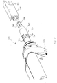
- the adapter tip 200 comprises a housing 204 having a mating interface 206 on its proximal end 208 configured to mechanically engage with the connector adapter 100 and a connection mechanism 210 on its distal end 212 to releasably attach to an optical-fiber inspection microscope probe 201.
- the housing 204 defines a light-relaying channel 216 between its proximal end 208 and its distal end 212 to relay the object beam from the optical-fiber endface 104 to the objective lens (see Fig. 8 ) of the inspection microscope probe 201.
- the housing 204 is made of a single integral piece of machined stainless steel but mechanically assemblies may alternatively be envisaged.
- the mating interface 206 has outer dimensions that are substantially complementary to inner dimensions of a connector-receiving channel 116 (see Fig. 1 ) of the connector adapter 100 so that it easily inserts into the connector adapter 100 in close proximity with the optical-fiber endface 104 to be inspected. Alignment of adapter tip 200 to the optical-fiber connector 102 is achieved by the small mechanical play of the mating interface 206 within the connector adapter 100.
- connection mechanism 210 is a screw-threaded mechanism including threads (not shown) on the external surface of the adapter tip 100.
- the inspection microscope probe 201 has a corresponding connection mechanism (not shown) comprising a swiveled threaded ring.
- One or more notches 214 are provided on the connection mechanism 210 which are to be received in corresponding keys (not shown) on the corresponding connection mechanism of the optical-fiber inspection microscope probe 201 to angularly lock the adapter tip 200 in place. It is noted that these notches 214 and keys are optional but ease the manipulations necessary to connect the adapter tip 200 to the inspection microscope probe 201.
- the adapter tip 200 is attached to the inspection microscope probe 201 by screwing the threaded ring on the threads of the connection mechanism 210.
- other solid and releasable connection mechanisms such as a bayonet connector for example may be used instead.
- the adapter tip 200 comprises a relay lens system 220 disposed within the light relaying channel 216 defined in the housing 204.
- the relay lens system 220 comprises a first relay lens 222 and a second relay lens 224.
- Relay lens 222 is disposed at the proximal end 208 of the adapter tip 200 so as to be adjacent to the inspected optical-fiber endface 104 when the adapter tip 200 is inserted in a connector adapter 100, in order to directly receive the object beam reflected from the optical-fiber endface 104 (through reflection of the illumination light).
- Relay lens 222 is positioned as close as possible to the proximal end 208 of the adapter tip 200 so as to capture as much of the divergent object beam as possible.
- Relay lens 222 is therefore positioned within the connector adapter 100 when the mating interface 206 of the adapter tip 100 is inserted into the connector-receiving channel 116 (see Fig. 1 ) of the connector adapter 100.
- Relay lens 224 is disposed the light relaying channel 216, spaced apart from relay lens 222.
- relay lens 222 and relay lens 224 cooperate to together deviate the object beam 126 towards the optical-fiber axis 800 of the connector 102 (see also Fig. 7 ) in order to allow it to exit the connector adapter 100 (see Fig. 7 ) and be captured by the objective lens 226 of the optical-fiber inspection microscope probe 201.
- Relay lens 222, relay lens 224 and the objective lens 226 defined an optical system 227.
- the object 804 to be imaged, i.e. the optical-fiber endface 104, lies in a real object plane 802, to within a focusing range of the optical-fiber inspection microscope probe 201.
- the relay lens system 220 reproduces the real object 804 that lies in the real object plane 802 on an intermediate image plane 806 that is tilted relative to the real object plane 802 toward a plane orthogonal to the optical-fiber axis 800, so as to reduce the angle between the normal of the intermediate image plane 802 and the optical-fiber axis 800 of the connector 102.
- the lens axis 808 of relay lens 222 is slightly offset relative to the optical-fiber endface 104 so that it is not aligned with and does not intersect the optical-fiber axis 800. It is slightly offset toward the direction corresponding to the rejection y of the normal n to the optical-fiber endface 104 on the optical-fiber axis 800.
- the lens axis 810 of relay lens 224 is also slightly offset relative to the center of relay lens 222 so that it is not aligned therewith.
- the objective lens 226 is disposed such that the intermediate image plane 806 lies on the original object plane 816 of the optical-fiber inspection microscope probe 201 (without the adapter tip 200) to within its focusing range.
- the lens axis 814 of the objective lens 226 (also referred to herein as the imaging and illumination axis 814 of the optical-fiber inspection microscope probe 201) is also slightly offset along y relative to the center of relay lens 224.
- the optical axes 808, 810 of both relay lenses 222, 224 are parallel to the optical-fiber axis 800, and therefore not normal to the inspected endface (there is an 8° angle between the normal n to the optical-fiber endface and the optical-fiber axis).
- the offsets reduce the amount of light blocked by the inside walls 128 (see Fig. 1 ) of the connector adapter 100, and also reduce the tilt of the intermediate image plane 806 created in front of the objective lens 226 relative to a plane orthogonal to the optical-fiber axis 800, by effectively rotating the intermediate image plane 806 relative to the real object plane 802.
- This tilt of the intermediate image plane 806 is reduced to a point where it can be neglected since the variation of focus across the image caused by the tilt remains below the diffraction limit of the imaging system of the optical-fiber inspection microscope system 202.
- the variation of the distance of the intermediate image plane 806 to the objective lens 226, which is caused by the tilt is smaller than the depths of field of the imaging system.
- the configuration described above allows placing the lenses such that their optical axes are all parallel (including the objective lens 226), which makes the adapter tip 200 much easier to manufacture with good precision in the relative orientations of the relay lenses 222, 224 and the objective lens 226.
- the normal n to the inspected optical-fiber endface104, and hence of the real object plane 802 forms an 8° angle relative to the imaging and illumination axis 814 of the optical-fiber inspection microscope probe 201.
- relay lenses 222 and 224 are compound lenses in order to provide low distortion and good off-axis performance.
- relay lenses 222 and 224 may each comprise an achromatic triplet lens made of a symmetric double convex lens element 820 cemented between two identical negative meniscus lens elements 822 having a refractive index higher than that of the convex lens element 820.
- the achromatic triplet lenses may be optimized for minimizing off-axis aberrations when employed with an infinite conjugate ratio, i.e. when focusing at infinity an object point placed at focal distance.
- relay lenses 222 and 224 each consist of a Hasting triplet lens.
- Hasting triplet lenses are optimized for an infinite conjugate ratio.
- Relay lens 222 is then disposed such that its focal point lies nearly on the real object plane 802.
- relay lens 224 is disposed relative to the objective lens 226 such that its focal point lies nearly on the original object plane 816 defined by the optical-fiber inspection microscope probe 201.
- relay lenses 222 and 224 are identical in design. In one embodiment, relay lenses 222 and 224 are identical Hasting triplet lenses each having an effective focal length of 8.875 mm and a diameter of 3.74 mm.
- Relay lens 222 is positioned in the adapter tip 200 so as to be disposed at the optical system's focal distance to the optical-fiber endface 104 during inspection. The distance between relay lenses 222 and 224 is 19.39 mm and relay lens 224 is positioned in the adapter tip 200 so as to be disposed at a distance of 32.35 mm to the objective lens 226 (the distances being defined along the imaging and illumination axis 814 of the optical-fiber inspection microscope probe 201, between the respective input surfaces of the lenses, i.e.
- the offset between the optical-fiber axis 800 and the lens axis 808 of relay lens 222 is 0.68 mm
- the offset between the lens axis 808 of relay lens 222 and the lens axis 810 of relay lens 224 is 0.24 mm
- the offset between the lens axis 810 of relay lens 224 and the lens axis 814 of the objective lens 226 is 0.63 mm.
- relay lenses 222, 224 are identical in design, it will be understood that this is not necessary and that relay lenses 222 and 224 may alternatively be different. Also, in other embodiment, more or less than two relay lenses 222, 224 may be employed.
- Fig. 9 illustrates an optical-fiber inspection microscope system 900 which employs the adapter tip 200 of Figs. 2-8 .
- the optical-fiber inspection microscope system 900 comprises a combination of an optical-fiber inspection microscope probe 902 and the adapter tip 200.
- the optical-fiber inspection microscope probe 902 at least contains an optical-fiber endface imaging assembly 904 comprising an illumination source 906, an objective lens 226, an image sensor 908 and a beam splitter 910.
- the illumination source 906 illuminates the optical-fiber endface 104 and can be embodied in a light-emitting diode (LED) typically emitting in the blue wavelength region.
- LED light-emitting diode
- the objective lens 226 directs the illumination light on the optical-fiber endface 104 to be imaged and captures light returned from the optical-fiber endface 104 through reflection of the illumination light in order to image the optical-fiber endface 104 on the image sensor 908 positioned on an image plane 912.
- the image sensor 908 may be embodied in a complementary metal-oxide-semiconductor (CMOS) sensor or a charge-coupled device (CCD), for instance.
- CMOS complementary metal-oxide-semiconductor
- CCD charge-coupled device
- the beam splitter 910 e.g. a 50/50 beam splitter, is located between the objective lens 226 and the image sensor 908. It both directs the illumination light toward the objective lens 226 for illuminating the optical-fiber endface 104 and propagates the returned object beam 126 from the objective lens 226 to the image sensor 908.
- optical-fiber inspection microscope probe 902 may be included in the optical-fiber inspection microscope probe 902 such as, for example, a power detection assembly (not shown) for measuring an optical power of light exiting the optical-fiber connector 102 at the optical-fiber endface 104, or any aberration compensation optical element(s).
- a power detection assembly (not shown) for measuring an optical power of light exiting the optical-fiber connector 102 at the optical-fiber endface 104, or any aberration compensation optical element(s).
- Fig. 10 shows an optical configuration of a non-claimed example of the adapter tipwherein respective optical axes of relay lenses 222', 224' are not parallel to the optical-fiber axis 800 of the optical-fiber connector 102 and wherein the lens axis of the objective lens 226 is also not parallel to the optical-fiber axis 800.
- relay lenses 222' and 224' are identical Hasting triplet lenses each having an effective focal length of 8.88 mm and a diameter of 3.74 mm.
- the angle between the lens axis of relay lens 222' and the normal n to the optical-fiber endface 104 is 6.45 degrees
- the angle between the lens axis of relay lens 224 and the normal n to the optical-fiber endface 104 is 4.67 degrees
- the angle between the lens axis of objective lens 226 and the normal n to the optical-fiber endface 104 is 7.54 degrees.
- Relay lens 222' is positioned in the adapter tip 200 so as to be disposed at the optical system's focal distance to the optical-fiber endface 104 during inspection.
- relay lens 222' and 224' are 19.39 mm and relay lens 224' is positioned in the adapter tip 200 so as to be disposed at a distance of 32.29 mm to the objective lens 226 (the distances being defined along the imaging and illumination axis 814 of the optical-fiber inspection microscope probe 201, between the respective input surfaces of the lenses).
- the offset between the center of the input surface 228' of relay lens 222' and that of the optical-fiber endface 104 is 0.68 mm
- the offset between the center of the input surface 230' of relay lens 224' and that of the input surface 228' of relay lens 222' is 0.26 mm
- the offset between the center of the input surface 232 of the objective lens 226 and that of the input surface 230' of relay lens 224' is 0.94 mm.
- adapter tip 200 may readily be adapted to implement the optical configuration of Fig. 10 .
- Fig. 11 shows an optical configuration in accordance with yet another embodiment wherein respective optical axes of relay lenses 222", 224" are parallel to the optical-fiber axis 800 of the optical-fiber connector 102 but wherein the lens axis of the objective lens 226 is not parallel to the optical-fiber axis 800.
- relay lenses 222" and 224" are identical Hasting triplet lenses each having an effective focal length of 8.876 mm and a diameter of 3.74 mm.
- the angle between the lens axis of objective lens 226 and the normal n to the optical-fiber endface 104 is 9.1 degrees.
- Relay lens 222" is positioned in the adapter tip 200 so as to be disposed at the optical system's focal distance to the optical-fiber endface 104 during inspection.
- the distance between relay lenses 222" and 224" is 19.39 mm and relay lens 224" is positioned in the adapter tip 200 so as to be disposed at a distance of 32.35 mm to the objective lens 226.
- the offset between the lens axis of relay lens 222" and the optical-fiber axis 800 is 0.64 mm
- the offset between the lens axis of relay lens 224" and the optical-fiber axis 800 is 0.07 mm
- the offset between the center of the input surface 232 of the objective lens 226 and that of relay lens 224" is 0.24 mm.
- adapter tip 200 may readily be adapted to implement the optical configuration of Fig. 11 .
- Fig. 12 shows an optical configuration in accordance with still another embodiment that consists of a single relay lens 222'" having its lens axis parallel to the optical-fiber axis 800 of the optical-fiber connector 102.
- the lens axis of the objective lens 226 is also parallel to the optical-fiber axis 800.
- relay lenses 222'" consists of a Hasting triplet lens.
- Relay lens 222'" is positioned in the adapter tip 200 so as to be disposed at the optical system's focal distance to the optical-fiber endface 104 during inspection.
- Relay lens 222'" is positioned in the adapter tip 200 so as to be disposed at a distance of 32.35 mm to the objective lens 226.
- the offset between the lens axis of relay lens 222'" and the optical-fiber axis 800 and the offset between the lens axis of the objective lens 226 and that of relay lens 222'" may be optimized to minimize aberrations in the image of the optical-fiber endface 104 on the image sensor 908.
- adapter tip 200 may readily be adapted to accommodate a single relay lens as in the optical configuration of Fig. 12 .
- the optical system 227 may be configured such that the illumination light reaches the optical fiber endface 104 at an orientation that is close the normal n to the endface. This is made possible by configuring the relay lens system 220 to redirect the illumination light, which is initially propagating along the imaging and illumination axis 814 of the optical-fiber inspection microscope probe 201, toward the normal n to the optical-fiber endface 104. This allows for the specular reflection on the optical-fiber endface 104 to be efficiently captured back by the relay lens system 220 and the objective lens 226.
- Fig. 13 shows an optical configuration in accordance with another embodiment that is so optimized to capture a maximum proportion of the object beam 126.
- the relay lens system 220 is configured so as to deviate the propagation of the illumination beam 1002 by an angle of 7.43° toward the normal n to the optical-fiber endface 104.
- the illumination beam 1002 thus aims on the optical-fiber endface 104 with an average propagation direction at an angle of 0.57° relative to the normal n, which allows capturing back a substantial proportion of the specular reflection on the endface 104 and thereby provides an excellent contrast on the captured image.
- suitable contrast can be achieved with an aiming angle of the illumination beam relative to the normal n lying between -2° and 2°.
- relay lens 1222 and relay lens 1224 of the optical configuration of Fig. 13 cooperate to together deviate the illumination beam 1002 toward the normal n to the optical-fiber endface 104 and to also deviate the object beam 126 towards the optical-fiber axis 800 of the connector 102 in order to be captured by the objective lens 226.
- the relay lens system 220 reproduces the real object 804 that lies in the real object plane 802 on an intermediate image plane 806 that is tilted relative to the real object plane 802 toward a plane orthogonal to the optical-fiber axis 800, so as to reduce the angle between the normal to the intermediate image plane 806 and the optical-fiber axis 800 of the connector 102.
- the lens axis 1008 of relay lens 1222 is slightly offset relative to the optical-fiber endface 104, toward the direction corresponding to the rejection y of the normal n to the optical-fiber endface 104 on the optical-fiber axis 800.
- the lens axis 1010 of relay lens 1224 is also slightly offset relative to the center of relay lens 1222 toward the same direction.
- the objective lens 226 is disposed such that the intermediate image plane 806 lies on the original object plane 816 of the optical-fiber inspection microscope probe 201 (without the adapter tip 200) to within its focusing range.
- the lens axis 814 of the objective lens 226 is also slightly offset along y relative to the center of relay lens 1224.
- the optical axes 1008, 1010 of both relay lenses 1222, 1224 are parallel to the optical-fiber axis 800, and therefore not normal to the inspected endface.
- the offsets reduce the amount of light blocked by the inside walls 128 (see Fig. 1 ) of the connector adapter 100, rotates the intermediate image plane 806 relative to the real object plane 802 and also deviate the illumination beam 1002 toward the normal n to the optical-fiber endface 104.
- the optical configuration of Fig. 13 further comprises correction optics 1228 embodied as an optical plate disposed at a non-zero angle relative to the lens axis 814 of the objective lens 226 (or, equivalently, relative to optical-fiber axis 800).
- correction optics 1228 is disposed between the objective lens 226 and relay lens 1224 but other configurations may be envisaged. It is noted that, in other embodiments, correction optics 1228 may be embodied, e.g., by an optical wedge or any other optical device providing the required correction.
- relay lenses 1222 and 1224 are identical Hasting triplet lenses each having an effective focal length of 8.66 mm and a diameter of 3.74 mm.
- the distance between the real object plane 802 and relay lens 1222 is 6.94 mm
- the distance between relay lenses 1222 and 1224 is 12.09 mm
- relay lens 1224 is positioned in the adapter tip 200 so as to be disposed at a distance of 33.82 mm to the objective lens 226 (the distances being defined along the imaging and illumination axis 814 of the optical-fiber inspection microscope probe 201 between the respective input surfaces of the lenses, i.e. the surface that is the closest to the object).
- the distance between the optical plate 1230 and relay lens 1224 is 15.47 mm (again defined between the input surfaces), the thickness of the optical plate 1228 is 2.2 mm and the angle between the optical plate 1228 and a plane orthogonal to the lens axis 814 of the objective lens 226 is 10.25°.
- the offset between the optical-fiber axis 800 and the lens axis 808 of relay lens 222 is 0.61 mm, the offset between the lens axis 808 of relay lens 222 and the lens axis 810 of relay lens 224 is 0.84 mm, and the offset between the lens axis 810 of relay lens 224 and the lens axis 814 of the objective lens 226 is 0.42 mm.
- Fig. 13 The optical configuration of Fig. 13 is otherwise similar to that of Fig. 8 and like features are not repeatedly described.
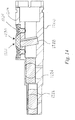
- Fig. 14 is a cross-sectional view of an adapter tip 1200 embodying the optical configuration of Fig. 13 .
- the adapter tip 1200 is configured to receive relay lens 1222, relay lens 1224 and correction optics 1228 of the optical configuration of Fig. 13 .
- a small window 1230 is machined in the housing 1204 of the adapter tip 1200.
- a cover plate 1232 is placed to close that window 1230 and is held in place using screws 1234.
- the adapter tip 1200 is otherwise similar to the adapter tip 200 of Figs. 2-7 and like features are therefore not repeatedly described.
Landscapes
- Physics & Mathematics (AREA)
- General Physics & Mathematics (AREA)
- Optics & Photonics (AREA)
- Chemical & Material Sciences (AREA)
- Analytical Chemistry (AREA)
- Microscoopes, Condenser (AREA)
Claims (13)
- Adapterspitze zur Verwendung mit einer Inspektionsmikroskopsonde (201) für eine Lichtleitfaser zum Abbilden einer Endfläche einer Lichtleitfaser (104) eines winklig geschliffenen Lichtleitfaser-Steckverbinders (102), der in einem Steckverbinderadapter (100) vertieft ist, wobei die Adapterspitze (200) umfasst:ein Gehäuse (204) mit einer passenden Schnittstelle (206), die dazu konfiguriert ist, mechanisch mit dem Steckverbinderadapter (100) in Eingriff zu kommen, um die Endfläche der Lichtleitfaser (104) in dem Steckverbinderadapter (100) zu untersuchen;ein Relaislinsensystem (220), das in dem Gehäuse (204) angeordnet ist und mindestens eine erste Relaislinse (222, 222', 222", 222"', 1222) aufweist, wobei die erste Relaislinse (222, 222', 222", 222"', 1222) so angeordnet ist, dass sie Licht, das von der Endfläche (104) der Lichtleitfaser reflektiert wird, während der Inspektion direkt aufnehmen kann,dadurch gekennzeichnet, dassdie Linsenachse (808) der ersten Relaislinse (222, 222', 222", 222"', 1222) relativ zu der Lichtleitfaserachse (800) versetzt ist, so dass die Linsenachse der ersten Relaislinse (222, 222', 222", 222"', 1222) nicht mit der Lichtleitfaserachse (800) fluchtet und Licht, das von der Endfläche (104) der Lichtleitfaser reflektiert wird, in Richtung der Lichtleitfaserachse (800) des Steckverbinders (102) abgeleitet wird, wobei die Linsenachse (808) der ersten Relaislinse (222, 222', 222", 222"', 1222) parallel zu der ersten Lichtleitfaserachse (800) verläuft.
- Adapterspitze nach Anspruch 1, wobei das Relaislinsensystem (220) des Weiteren eine zweite Relaislinse (224, 224', 244", 1224) umfasst, welche die erste Relaislinse (222, 222', 222", 222"', 1222) beabstandet und mit der ersten Relaislinse (222, 222', 222", 222"', 1222) zusammenwirkt, um Licht, das von der Endfläche (104) der Lichtleitfaser reflektiert wird, in Richtung der Lichtleitfaserachse (800) des Steckverbinders (102) abzuleiten.
- Adapterspitze nach Anspruch 2, wobei eine Mitte einer Eingangsfläche der zweiten Relaislinse (224, 224', 224", 1224) relativ zu der Linsenachse der ersten Relaislinse (222, 222', 222", 222"', 1222) versetzt ist.
- Adapterspitze nach Anspruch 3, wobei das Relaislinsensystem (220) eine Zwischenbildebene erzeugt, die relativ zu der realen Objektebene, auf welcher die Endfläche (104) der Lichtleitfaser liegt, in Richtung einer Ebene geneigt ist, die orthogonal zu der Lichtleitfaserachse des Steckverbinders (102) ausgerichtet ist.
- Adapterspitze nach Anspruch 1, wobei die Adapterspitze (200) Beleuchtungslicht von der Inspektionsmikroskopsonde (201) für eine Lichtleitfaser während der Inspektion aufnimmt, um die Endfläche (104) der Lichtleitfaser abzubilden, und wobei das Relaislinsensystem (220) das Beleuchtungslicht im Wesentlichen normal zu der Endfläche (104) der Lichtleitfaser umleitet.
- Adapterspitze nach Anspruch 1 oder 5, des Weiteren umfassend Korrekturoptik (1228) zur Korrektur von optischen Aberrationen, die durch das Relaislinsensystem (220) erzeugt werden, und wobei die Korrekturoptik (1228) eine optische Platte umfasst, die auf einem Nicht-Null-Winkel relativ zu der Lichtleitfaserachse (800) des Steckverbinders (102) angeordnet ist.
- Adapterspitze nach einem der Ansprüche 2 bis 5, wobei die Linsenachse der ersten Relaislinse (222, 222', 222", 222"', 1222) und die Linsenachse der zweiten Relaislinse (224, 224', 224", 1224) beide parallel zu der Lichtleitfaserachse und parallel zu einer Linsenachse einer Objektivlinse der Inspektionsmikroskopsonde (201) für Lichtleitfasern sind.
- Inspektionsmikroskopsystem für Lichtleitfasern zum Abbilden einer Endfläche (104) einer Lichtleitfaser eines winklig geschliffenen Lichtleitfaser-Steckverbinders, der in einem Kanal vertieft ist, dadurch gekennzeichnet, dass das Mikroskopsystem umfasst:die Adapterspitze (200) nach Anspruch 1 und eine Inspektionsmikroskopsonde (201) für Lichtleitfasern; undwobei die Adapterspitze (200) mit der Inspektionsmikroskopsonde (201) für Lichtleitfasern verbindbar ist.
- Inspektionsmikroskopsystem für Lichtleitfasern nach Anspruch 8, wobei das Relaislinsensystem (220) des Weiteren eine zweite Relaislinse (224, 224', 244", 1224) umfasst, welche die erste Relaislinse (222, 222', 222", 222"', 1222) beabstandet und mit der ersten Relaislinse (222, 222', 222", 222"', 1222) zusammenwirkt, um Licht, das von der Endfläche (104) der Lichtleitfaser reflektiert wird, in Richtung der Lichtleitfaserachse des Steckverbinders (102) abzuleiten.
- Inspektionsmikroskopsystem für Lichtleitfasern nach Anspruch 9, wobei
eine Mitte einer Eingangsfläche der zweiten Relaislinse (224, 224', 224", 1224) relativ zu der Linsenachse der ersten Relaislinse (222, 222', 222", 222"', 1222) versetzt ist. - Adapterspitze nach Anspruch 10, wobei das Relaislinsensystem (220) eine Zwischenbildebene erzeugt, die relativ zu der realen Objektebene, auf welcher die Endfläche (104) der Lichtleitfaser liegt, in Richtung einer Ebene geneigt ist, die orthogonal zu der Lichtleitfaserachse des Steckverbinders (102) ausgerichtet ist.
- Inspektionsmikroskopsystem für Lichtleitfasern nach Anspruch 8, wobei die Adapterspitze (200) Beleuchtungslicht von der Inspektionsmikroskopsonde (201) für eine Lichtleitfaser während der Inspektion aufnimmt, um die Endfläche (104) der Lichtleitfaser abzubilden, und wobei das Relaislinsensystem (220) das Beleuchtungslicht im Wesentlichen normal zu der Endfläche (104) der Lichtleitfaser umleitet.
- Inspektionsmikroskopsystem für Lichtleitfasern nach einem der Ansprüche 8 bis 11, wobei die Linsenachse der ersten Relaislinse (222, 222', 222", 222"', 1222) und die Linsenachse der zweiten Relaislinse (224, 224', 224", 1224) beide parallel zu der Lichtleitfaserachse (800) und parallel zu einer Linsenachse einer Objektivlinse der Inspektionsmikroskopsonde (201) für Lichtleitfasern sind.
Applications Claiming Priority (3)
| Application Number | Priority Date | Filing Date | Title |
|---|---|---|---|
| US201562164868P | 2015-05-21 | 2015-05-21 | |
| US201562188552P | 2015-07-03 | 2015-07-03 | |
| US201562248727P | 2015-10-30 | 2015-10-30 |
Publications (2)
| Publication Number | Publication Date |
|---|---|
| EP3096124A1 EP3096124A1 (de) | 2016-11-23 |
| EP3096124B1 true EP3096124B1 (de) | 2018-09-05 |
Family
ID=56080257
Family Applications (1)
| Application Number | Title | Priority Date | Filing Date |
|---|---|---|---|
| EP16170510.8A Active EP3096124B1 (de) | 2015-05-21 | 2016-05-20 | Adapterspitze und mikroskopsystem zur inspektion einer faseroptischen steckerendfläche |
Country Status (2)
| Country | Link |
|---|---|
| US (1) | US9880359B2 (de) |
| EP (1) | EP3096124B1 (de) |
Families Citing this family (18)
| Publication number | Priority date | Publication date | Assignee | Title |
|---|---|---|---|---|
| WO2017007690A1 (en) * | 2015-07-06 | 2017-01-12 | Indiana University Research And Technology Corporation | Fluorescent microscope |
| US10578847B2 (en) * | 2016-05-25 | 2020-03-03 | Edward John Forrest, Jr. | Fiber optic connection inspection apparatus and method |
| US9797806B1 (en) * | 2017-03-02 | 2017-10-24 | Lightel Technologies, Inc. | PC/APC dual-purpose adapter for inspecting circular ruggedized fiber optic connectors |
| US10524345B2 (en) | 2017-04-28 | 2019-12-31 | Taiwan Semiconductor Manufacturing Co., Ltd. | Residual gain monitoring and reduction for EUV drive laser |
| US10101570B1 (en) * | 2017-06-01 | 2018-10-16 | Lightel Technologies, Inc. | Optical fiber connector inspector with two-dimensional scanning function |
| EP3824262A4 (de) | 2018-07-17 | 2022-03-30 | CommScope Technologies LLC | Inspektionswerkzeug für faseroptische ferrule |
| CN112805604A (zh) * | 2018-09-05 | 2021-05-14 | 扇港元器件股份有限公司 | 用于光纤的具有自调节棱镜的检查尖端和方法 |
| US10649154B1 (en) * | 2019-02-20 | 2020-05-12 | Lightel Technologies, Inc. | Field of view converter for fiber-optic connector endface inspector |
| US11086080B2 (en) * | 2019-05-29 | 2021-08-10 | Viavi Solutions Inc. | Alignment guide for inspecting a fiber optic end face |
| US11099331B2 (en) * | 2019-07-18 | 2021-08-24 | 3M Innovative Properties Company | Optical adaptor |
| CN110487805B (zh) * | 2019-09-17 | 2025-05-16 | 深圳市维度科技股份有限公司 | 一种用于光纤连接器端面检测的接口 |
| CN111189850B (zh) * | 2020-03-02 | 2024-08-13 | 深圳市维度科技股份有限公司 | 一种用于光纤连接器端面检测的接口 |
| CA3125161A1 (en) | 2020-07-31 | 2022-01-31 | Exfo Inc. | Adapter tip and microscope system for inspection of fiber-optic connector endfaces |
| US12050149B2 (en) | 2020-11-27 | 2024-07-30 | Exfo Inc. | Optical fiber endface inspection microscope having a swappable optical head |
| US12078854B2 (en) * | 2021-04-23 | 2024-09-03 | US Conec, Ltd | Optical assembly |
| US12429653B2 (en) | 2022-05-11 | 2025-09-30 | Exfo Inc. | Adapter tip and microscope system for inspecting duplex fiber-optic connector endfaces |
| US12546681B2 (en) * | 2023-06-02 | 2026-02-10 | Viavi Solutions Inc. | Changeable tip for optical fiber inspection device |
| EP4644959A1 (de) | 2024-04-30 | 2025-11-05 | EXFO Inc. | Faseroptisches endflächeninspektionsmikroskop, das native für abgewinkelte polierte verbinder angepasst ist |
Family Cites Families (5)
| Publication number | Priority date | Publication date | Assignee | Title |
|---|---|---|---|---|
| US6215924B1 (en) * | 1998-08-06 | 2001-04-10 | Optical Coating Laboratory, Inc. | Optical coupler device for dense wavelength division multiplexing |
| US7356236B1 (en) * | 2006-12-14 | 2008-04-08 | Lightel Technologies Inc. | Field-use apparatus for inspecting and cleaning fiber optic connectors |
| US8164744B2 (en) | 2008-10-30 | 2012-04-24 | Adc Telecommunications, Inc. | Inspection tip for a fiber optic inspection probe |
| WO2013097041A1 (en) * | 2011-12-28 | 2013-07-04 | Exfo Inc. | Portable digital holographic probe for the inspection of optical fiber connectors, and inspection system and method for the same |
| US8976345B2 (en) | 2013-06-04 | 2015-03-10 | Lightel Technologies, Inc. | Fitting tip with relay lens for fiber-optic connector endface inspector |
-
2016
- 2016-05-20 EP EP16170510.8A patent/EP3096124B1/de active Active
- 2016-05-20 US US15/160,398 patent/US9880359B2/en active Active
Also Published As
| Publication number | Publication date |
|---|---|
| US20160341904A1 (en) | 2016-11-24 |
| US9880359B2 (en) | 2018-01-30 |
| EP3096124A1 (de) | 2016-11-23 |
Similar Documents
| Publication | Publication Date | Title |
|---|---|---|
| EP3096124B1 (de) | Adapterspitze und mikroskopsystem zur inspektion einer faseroptischen steckerendfläche | |
| EP3945352B1 (de) | Adapterspitze und mikroskopsystem zur inspektion von faseroptischen steckerendflächen | |
| CN105700123B (zh) | 光纤检查显微镜与功率测量系统、光纤检查尖端及其使用方法 | |
| US9841579B2 (en) | Multiple-fiber connector inspection | |
| CA2751329C (en) | Fiber optic jack and connector | |
| US6793399B1 (en) | System and method for optical port inspection for telecommunication systems and devices | |
| US8976345B2 (en) | Fitting tip with relay lens for fiber-optic connector endface inspector | |
| US12429653B2 (en) | Adapter tip and microscope system for inspecting duplex fiber-optic connector endfaces | |
| US11274991B2 (en) | Fiber optic ferrule inspection tool | |
| US10900866B2 (en) | Optical fiber endface inspection with optical power measurement | |
| WO2013097041A1 (en) | Portable digital holographic probe for the inspection of optical fiber connectors, and inspection system and method for the same | |
| US12050149B2 (en) | Optical fiber endface inspection microscope having a swappable optical head | |
| US12455417B2 (en) | MPO adapter for APC connector inspection | |
| US11849202B2 (en) | System for illuminating and viewing recessed angled surfaces | |
| US20240255713A1 (en) | Adapter tip and microscope system for inspecting apc trans-duplex fiber-optic connectors | |
| US20250076625A1 (en) | Adapter tip and microscope system for inspecting angled-polished optical-fiber connectors | |
| US20210215572A1 (en) | Inspection Tip Having a Self-Adjusting Prism for an Optical Fiber and Method of Use | |
| JPH08304017A (ja) | 光コネクタ端面の凸球面偏心簡易測定器 |
Legal Events
| Date | Code | Title | Description |
|---|---|---|---|
| PUAI | Public reference made under article 153(3) epc to a published international application that has entered the european phase |
Free format text: ORIGINAL CODE: 0009012 |
|
| AK | Designated contracting states |
Kind code of ref document: A1 Designated state(s): AL AT BE BG CH CY CZ DE DK EE ES FI FR GB GR HR HU IE IS IT LI LT LU LV MC MK MT NL NO PL PT RO RS SE SI SK SM TR |
|
| AX | Request for extension of the european patent |
Extension state: BA ME |
|
| STAA | Information on the status of an ep patent application or granted ep patent |
Free format text: STATUS: REQUEST FOR EXAMINATION WAS MADE |
|
| 17P | Request for examination filed |
Effective date: 20170523 |
|
| RBV | Designated contracting states (corrected) |
Designated state(s): AL AT BE BG CH CY CZ DE DK EE ES FI FR GB GR HR HU IE IS IT LI LT LU LV MC MK MT NL NO PL PT RO RS SE SI SK SM TR |
|
| GRAP | Despatch of communication of intention to grant a patent |
Free format text: ORIGINAL CODE: EPIDOSNIGR1 |
|
| STAA | Information on the status of an ep patent application or granted ep patent |
Free format text: STATUS: GRANT OF PATENT IS INTENDED |
|
| INTG | Intention to grant announced |
Effective date: 20180328 |
|
| GRAS | Grant fee paid |
Free format text: ORIGINAL CODE: EPIDOSNIGR3 |
|
| GRAA | (expected) grant |
Free format text: ORIGINAL CODE: 0009210 |
|
| STAA | Information on the status of an ep patent application or granted ep patent |
Free format text: STATUS: THE PATENT HAS BEEN GRANTED |
|
| RAP1 | Party data changed (applicant data changed or rights of an application transferred) |
Owner name: EXFO INC. |
|
| AK | Designated contracting states |
Kind code of ref document: B1 Designated state(s): AL AT BE BG CH CY CZ DE DK EE ES FI FR GB GR HR HU IE IS IT LI LT LU LV MC MK MT NL NO PL PT RO RS SE SI SK SM TR |
|
| REG | Reference to a national code |
Ref country code: GB Ref legal event code: FG4D |
|
| REG | Reference to a national code |
Ref country code: CH Ref legal event code: EP |
|
| REG | Reference to a national code |
Ref country code: AT Ref legal event code: REF Ref document number: 1038381 Country of ref document: AT Kind code of ref document: T Effective date: 20180915 |
|
| REG | Reference to a national code |
Ref country code: IE Ref legal event code: FG4D |
|
| REG | Reference to a national code |
Ref country code: DE Ref legal event code: R096 Ref document number: 602016005282 Country of ref document: DE |
|
| REG | Reference to a national code |
Ref country code: NL Ref legal event code: MP Effective date: 20180905 |
|
| REG | Reference to a national code |
Ref country code: LT Ref legal event code: MG4D |
|
| PG25 | Lapsed in a contracting state [announced via postgrant information from national office to epo] |
Ref country code: LT Free format text: LAPSE BECAUSE OF FAILURE TO SUBMIT A TRANSLATION OF THE DESCRIPTION OR TO PAY THE FEE WITHIN THE PRESCRIBED TIME-LIMIT Effective date: 20180905 Ref country code: RS Free format text: LAPSE BECAUSE OF FAILURE TO SUBMIT A TRANSLATION OF THE DESCRIPTION OR TO PAY THE FEE WITHIN THE PRESCRIBED TIME-LIMIT Effective date: 20180905 Ref country code: BG Free format text: LAPSE BECAUSE OF FAILURE TO SUBMIT A TRANSLATION OF THE DESCRIPTION OR TO PAY THE FEE WITHIN THE PRESCRIBED TIME-LIMIT Effective date: 20181205 Ref country code: NO Free format text: LAPSE BECAUSE OF FAILURE TO SUBMIT A TRANSLATION OF THE DESCRIPTION OR TO PAY THE FEE WITHIN THE PRESCRIBED TIME-LIMIT Effective date: 20181205 Ref country code: SE Free format text: LAPSE BECAUSE OF FAILURE TO SUBMIT A TRANSLATION OF THE DESCRIPTION OR TO PAY THE FEE WITHIN THE PRESCRIBED TIME-LIMIT Effective date: 20180905 Ref country code: GR Free format text: LAPSE BECAUSE OF FAILURE TO SUBMIT A TRANSLATION OF THE DESCRIPTION OR TO PAY THE FEE WITHIN THE PRESCRIBED TIME-LIMIT Effective date: 20181206 Ref country code: FI Free format text: LAPSE BECAUSE OF FAILURE TO SUBMIT A TRANSLATION OF THE DESCRIPTION OR TO PAY THE FEE WITHIN THE PRESCRIBED TIME-LIMIT Effective date: 20180905 |
|
| REG | Reference to a national code |
Ref country code: AT Ref legal event code: MK05 Ref document number: 1038381 Country of ref document: AT Kind code of ref document: T Effective date: 20180905 |
|
| PG25 | Lapsed in a contracting state [announced via postgrant information from national office to epo] |
Ref country code: HR Free format text: LAPSE BECAUSE OF FAILURE TO SUBMIT A TRANSLATION OF THE DESCRIPTION OR TO PAY THE FEE WITHIN THE PRESCRIBED TIME-LIMIT Effective date: 20180905 Ref country code: LV Free format text: LAPSE BECAUSE OF FAILURE TO SUBMIT A TRANSLATION OF THE DESCRIPTION OR TO PAY THE FEE WITHIN THE PRESCRIBED TIME-LIMIT Effective date: 20180905 Ref country code: AL Free format text: LAPSE BECAUSE OF FAILURE TO SUBMIT A TRANSLATION OF THE DESCRIPTION OR TO PAY THE FEE WITHIN THE PRESCRIBED TIME-LIMIT Effective date: 20180905 |
|
| PG25 | Lapsed in a contracting state [announced via postgrant information from national office to epo] |
Ref country code: CZ Free format text: LAPSE BECAUSE OF FAILURE TO SUBMIT A TRANSLATION OF THE DESCRIPTION OR TO PAY THE FEE WITHIN THE PRESCRIBED TIME-LIMIT Effective date: 20180905 Ref country code: RO Free format text: LAPSE BECAUSE OF FAILURE TO SUBMIT A TRANSLATION OF THE DESCRIPTION OR TO PAY THE FEE WITHIN THE PRESCRIBED TIME-LIMIT Effective date: 20180905 Ref country code: IT Free format text: LAPSE BECAUSE OF FAILURE TO SUBMIT A TRANSLATION OF THE DESCRIPTION OR TO PAY THE FEE WITHIN THE PRESCRIBED TIME-LIMIT Effective date: 20180905 Ref country code: AT Free format text: LAPSE BECAUSE OF FAILURE TO SUBMIT A TRANSLATION OF THE DESCRIPTION OR TO PAY THE FEE WITHIN THE PRESCRIBED TIME-LIMIT Effective date: 20180905 Ref country code: NL Free format text: LAPSE BECAUSE OF FAILURE TO SUBMIT A TRANSLATION OF THE DESCRIPTION OR TO PAY THE FEE WITHIN THE PRESCRIBED TIME-LIMIT Effective date: 20180905 Ref country code: PL Free format text: LAPSE BECAUSE OF FAILURE TO SUBMIT A TRANSLATION OF THE DESCRIPTION OR TO PAY THE FEE WITHIN THE PRESCRIBED TIME-LIMIT Effective date: 20180905 Ref country code: IS Free format text: LAPSE BECAUSE OF FAILURE TO SUBMIT A TRANSLATION OF THE DESCRIPTION OR TO PAY THE FEE WITHIN THE PRESCRIBED TIME-LIMIT Effective date: 20190105 Ref country code: EE Free format text: LAPSE BECAUSE OF FAILURE TO SUBMIT A TRANSLATION OF THE DESCRIPTION OR TO PAY THE FEE WITHIN THE PRESCRIBED TIME-LIMIT Effective date: 20180905 Ref country code: ES Free format text: LAPSE BECAUSE OF FAILURE TO SUBMIT A TRANSLATION OF THE DESCRIPTION OR TO PAY THE FEE WITHIN THE PRESCRIBED TIME-LIMIT Effective date: 20180905 |
|
| PG25 | Lapsed in a contracting state [announced via postgrant information from national office to epo] |
Ref country code: PT Free format text: LAPSE BECAUSE OF FAILURE TO SUBMIT A TRANSLATION OF THE DESCRIPTION OR TO PAY THE FEE WITHIN THE PRESCRIBED TIME-LIMIT Effective date: 20190105 Ref country code: SK Free format text: LAPSE BECAUSE OF FAILURE TO SUBMIT A TRANSLATION OF THE DESCRIPTION OR TO PAY THE FEE WITHIN THE PRESCRIBED TIME-LIMIT Effective date: 20180905 Ref country code: SM Free format text: LAPSE BECAUSE OF FAILURE TO SUBMIT A TRANSLATION OF THE DESCRIPTION OR TO PAY THE FEE WITHIN THE PRESCRIBED TIME-LIMIT Effective date: 20180905 |
|
| REG | Reference to a national code |
Ref country code: DE Ref legal event code: R097 Ref document number: 602016005282 Country of ref document: DE |
|
| PLBE | No opposition filed within time limit |
Free format text: ORIGINAL CODE: 0009261 |
|
| STAA | Information on the status of an ep patent application or granted ep patent |
Free format text: STATUS: NO OPPOSITION FILED WITHIN TIME LIMIT |
|
| PG25 | Lapsed in a contracting state [announced via postgrant information from national office to epo] |
Ref country code: DK Free format text: LAPSE BECAUSE OF FAILURE TO SUBMIT A TRANSLATION OF THE DESCRIPTION OR TO PAY THE FEE WITHIN THE PRESCRIBED TIME-LIMIT Effective date: 20180905 |
|
| 26N | No opposition filed |
Effective date: 20190606 |
|
| PG25 | Lapsed in a contracting state [announced via postgrant information from national office to epo] |
Ref country code: SI Free format text: LAPSE BECAUSE OF FAILURE TO SUBMIT A TRANSLATION OF THE DESCRIPTION OR TO PAY THE FEE WITHIN THE PRESCRIBED TIME-LIMIT Effective date: 20180905 |
|
| REG | Reference to a national code |
Ref country code: CH Ref legal event code: PL |
|
| PG25 | Lapsed in a contracting state [announced via postgrant information from national office to epo] |
Ref country code: MC Free format text: LAPSE BECAUSE OF FAILURE TO SUBMIT A TRANSLATION OF THE DESCRIPTION OR TO PAY THE FEE WITHIN THE PRESCRIBED TIME-LIMIT Effective date: 20180905 Ref country code: CH Free format text: LAPSE BECAUSE OF NON-PAYMENT OF DUE FEES Effective date: 20190531 Ref country code: LI Free format text: LAPSE BECAUSE OF NON-PAYMENT OF DUE FEES Effective date: 20190531 |
|
| REG | Reference to a national code |
Ref country code: BE Ref legal event code: MM Effective date: 20190531 |
|
| PG25 | Lapsed in a contracting state [announced via postgrant information from national office to epo] |
Ref country code: LU Free format text: LAPSE BECAUSE OF NON-PAYMENT OF DUE FEES Effective date: 20190520 |
|
| PG25 | Lapsed in a contracting state [announced via postgrant information from national office to epo] |
Ref country code: TR Free format text: LAPSE BECAUSE OF FAILURE TO SUBMIT A TRANSLATION OF THE DESCRIPTION OR TO PAY THE FEE WITHIN THE PRESCRIBED TIME-LIMIT Effective date: 20180905 |
|
| PG25 | Lapsed in a contracting state [announced via postgrant information from national office to epo] |
Ref country code: IE Free format text: LAPSE BECAUSE OF NON-PAYMENT OF DUE FEES Effective date: 20190520 |
|
| PG25 | Lapsed in a contracting state [announced via postgrant information from national office to epo] |
Ref country code: BE Free format text: LAPSE BECAUSE OF NON-PAYMENT OF DUE FEES Effective date: 20190531 |
|
| PG25 | Lapsed in a contracting state [announced via postgrant information from national office to epo] |
Ref country code: CY Free format text: LAPSE BECAUSE OF FAILURE TO SUBMIT A TRANSLATION OF THE DESCRIPTION OR TO PAY THE FEE WITHIN THE PRESCRIBED TIME-LIMIT Effective date: 20180905 |
|
| PG25 | Lapsed in a contracting state [announced via postgrant information from national office to epo] |
Ref country code: HU Free format text: LAPSE BECAUSE OF FAILURE TO SUBMIT A TRANSLATION OF THE DESCRIPTION OR TO PAY THE FEE WITHIN THE PRESCRIBED TIME-LIMIT; INVALID AB INITIO Effective date: 20160520 Ref country code: MT Free format text: LAPSE BECAUSE OF FAILURE TO SUBMIT A TRANSLATION OF THE DESCRIPTION OR TO PAY THE FEE WITHIN THE PRESCRIBED TIME-LIMIT Effective date: 20180905 |
|
| REG | Reference to a national code |
Ref country code: DE Ref legal event code: R082 Ref document number: 602016005282 Country of ref document: DE Representative=s name: ZACCO LEGAL RECHTSANWALTSGESELLSCHAFT MBH, DE |
|
| PG25 | Lapsed in a contracting state [announced via postgrant information from national office to epo] |
Ref country code: MK Free format text: LAPSE BECAUSE OF FAILURE TO SUBMIT A TRANSLATION OF THE DESCRIPTION OR TO PAY THE FEE WITHIN THE PRESCRIBED TIME-LIMIT Effective date: 20180905 |
|
| REG | Reference to a national code |
Ref country code: FR Ref legal event code: PLFP Year of fee payment: 8 |
|
| P01 | Opt-out of the competence of the unified patent court (upc) registered |
Effective date: 20230513 |
|
| PGFP | Annual fee paid to national office [announced via postgrant information from national office to epo] |
Ref country code: DE Payment date: 20250409 Year of fee payment: 10 |
|
| PGFP | Annual fee paid to national office [announced via postgrant information from national office to epo] |
Ref country code: FR Payment date: 20250409 Year of fee payment: 10 |
|
| REG | Reference to a national code |
Ref country code: DE Ref legal event code: R082 Ref document number: 602016005282 Country of ref document: DE |
|
| PGFP | Annual fee paid to national office [announced via postgrant information from national office to epo] |
Ref country code: GB Payment date: 20260320 Year of fee payment: 11 |