EP3945199B1 - Climbing product having an extendable section lock assembly, and methods for using and producing a climbing product - Google Patents
Climbing product having an extendable section lock assembly, and methods for using and producing a climbing product Download PDFInfo
- Publication number
- EP3945199B1 EP3945199B1 EP21188560.3A EP21188560A EP3945199B1 EP 3945199 B1 EP3945199 B1 EP 3945199B1 EP 21188560 A EP21188560 A EP 21188560A EP 3945199 B1 EP3945199 B1 EP 3945199B1
- Authority
- EP
- European Patent Office
- Prior art keywords
- lock
- fly
- base
- section
- flip
- Prior art date
- Legal status (The legal status is an assumption and is not a legal conclusion. Google has not performed a legal analysis and makes no representation as to the accuracy of the status listed.)
- Active
Links
Images




















Classifications
-
- E—FIXED CONSTRUCTIONS
- E06—DOORS, WINDOWS, SHUTTERS, OR ROLLER BLINDS IN GENERAL; LADDERS
- E06C—LADDERS
- E06C1/00—Ladders in general
- E06C1/02—Ladders in general with rigid longitudinal member or members
- E06C1/04—Ladders for resting against objects, e.g. walls poles, trees
- E06C1/08—Ladders for resting against objects, e.g. walls poles, trees multi-part
- E06C1/12—Ladders for resting against objects, e.g. walls poles, trees multi-part extensible, e.g. telescopic
-
- E—FIXED CONSTRUCTIONS
- E06—DOORS, WINDOWS, SHUTTERS, OR ROLLER BLINDS IN GENERAL; LADDERS
- E06C—LADDERS
- E06C1/00—Ladders in general
- E06C1/02—Ladders in general with rigid longitudinal member or members
- E06C1/04—Ladders for resting against objects, e.g. walls poles, trees
- E06C1/08—Ladders for resting against objects, e.g. walls poles, trees multi-part
- E06C1/12—Ladders for resting against objects, e.g. walls poles, trees multi-part extensible, e.g. telescopic
- E06C1/125—Ladders for resting against objects, e.g. walls poles, trees multi-part extensible, e.g. telescopic with tubular longitudinal members nested within each other
-
- E—FIXED CONSTRUCTIONS
- E06—DOORS, WINDOWS, SHUTTERS, OR ROLLER BLINDS IN GENERAL; LADDERS
- E06C—LADDERS
- E06C1/00—Ladders in general
- E06C1/02—Ladders in general with rigid longitudinal member or members
- E06C1/14—Ladders capable of standing by themselves
- E06C1/16—Ladders capable of standing by themselves with hinged struts which rest on the ground
- E06C1/18—Ladders capable of standing by themselves with hinged struts which rest on the ground with supporting struts formed as ladders
-
- E—FIXED CONSTRUCTIONS
- E06—DOORS, WINDOWS, SHUTTERS, OR ROLLER BLINDS IN GENERAL; LADDERS
- E06C—LADDERS
- E06C1/00—Ladders in general
- E06C1/02—Ladders in general with rigid longitudinal member or members
- E06C1/14—Ladders capable of standing by themselves
- E06C1/16—Ladders capable of standing by themselves with hinged struts which rest on the ground
- E06C1/20—Ladders capable of standing by themselves with hinged struts which rest on the ground with supporting struts formed as poles
- E06C1/22—Ladders capable of standing by themselves with hinged struts which rest on the ground with supporting struts formed as poles with extensible, e.g. telescopic, ladder parts or struts
-
- E—FIXED CONSTRUCTIONS
- E06—DOORS, WINDOWS, SHUTTERS, OR ROLLER BLINDS IN GENERAL; LADDERS
- E06C—LADDERS
- E06C7/00—Component parts, supporting parts, or accessories
- E06C7/02—Extending means
-
- E—FIXED CONSTRUCTIONS
- E06—DOORS, WINDOWS, SHUTTERS, OR ROLLER BLINDS IN GENERAL; LADDERS
- E06C—LADDERS
- E06C7/00—Component parts, supporting parts, or accessories
- E06C7/02—Extending means
- E06C7/04—Hand-operated extending means carried by the ladder
-
- E—FIXED CONSTRUCTIONS
- E06—DOORS, WINDOWS, SHUTTERS, OR ROLLER BLINDS IN GENERAL; LADDERS
- E06C—LADDERS
- E06C7/00—Component parts, supporting parts, or accessories
- E06C7/06—Securing devices or hooks for parts of extensible ladders
-
- E—FIXED CONSTRUCTIONS
- E06—DOORS, WINDOWS, SHUTTERS, OR ROLLER BLINDS IN GENERAL; LADDERS
- E06C—LADDERS
- E06C7/00—Component parts, supporting parts, or accessories
- E06C7/08—Special construction of longitudinal members, or rungs or other treads
-
- E—FIXED CONSTRUCTIONS
- E06—DOORS, WINDOWS, SHUTTERS, OR ROLLER BLINDS IN GENERAL; LADDERS
- E06C—LADDERS
- E06C7/00—Component parts, supporting parts, or accessories
- E06C7/42—Ladder feet; Supports therefor
-
- E—FIXED CONSTRUCTIONS
- E06—DOORS, WINDOWS, SHUTTERS, OR ROLLER BLINDS IN GENERAL; LADDERS
- E06C—LADDERS
- E06C7/00—Component parts, supporting parts, or accessories
- E06C7/50—Joints or other connecting parts
Definitions
- the present invention pertains to a climbing product having an extendable section lock assembly.
- references to the "present invention” or “invention” relate to exemplary embodiments and not necessarily to every embodiment encompassed by the appended claims.
- the present invention pertains to a climbing product having an extendable section lock assembly where the lock assembly includes a fly lock portion attached to a fly section of the climbing product which locks with a base section of the climbing product, and which unlocks from the base section simply by the fly section being lifted relative to the base section.
- Document US 5 000 289 A discloses a folding step ladder composed of four ladder elements: an upper-front element joined to an upper-rear element at a top hinge-step, a lower-front element slidingly joined to the upper-front element along its length, and a lower-rear element slidingly joined to the upper-rear element along its length.
- the lower elements captively slide along the length of their corresponding upper element and are capable of being held at a particular incremental extension by a latch arrangement that engages the upper element when downward force is exerted on the ladder.
- the present invention pertains to a climbing product as set out in claim 1 below.
- the present invention pertains to a method for using a climbing product as set out in claim 7 below.
- the present invention pertains to a method for producing a climbing product as set out in claim 8 below.
- the climbing product comprises a base section 12 having a first base rail 14 and a second base rail 16 in parallel and spaced relationship with the first base rail 14 and base rungs 18 attached to and between the first and second base rails 14, 16.
- the climbing product comprises a fly section 20 having a first fly rail 22 and a second fly rail 24 in parallel and spaced relationship with the first fly rail 22 and fly rungs 26 attached to and between the first and second fly rails 22, 24.
- the fly section 20 in sliding engagement with the base section 12.
- the climbing product comprises a lock assembly 28 having a lock fly portion 30 directly attached to the fly section 20.
- the lock fly portion 30 directly engages with the base section 12 to lock the base section 12 with the fly section 20.
- the lock fly portion 30 disengages from the lock base portion 32 by simply moving the fly section 20 relative to the base section 12 to unlock the fly section 20 from the base section 12.
- the climbing product 10 may include but not be limited to MT ladders, leaning ladders, and work platforms.
- the lock assembly 28 may include a lock base portion 32 directly attached to the base section 12, as shown in figures 3-10 and 18-21 .
- the lock fly portion 30 directly engages with the lock base portion 32 to lock the fly section 20 to the base section 12.
- the lock fly portion 30 disengages from the lock base portion 32 by simply moving the fly section 20 relative to the base section 12 to unlock the fly section 20 from the base section 12.
- the lock base portion 32 may include a socket 34 disposed in one of the base rungs 18, and the lock fly portion 30 includes a flip lock 36 which fits into the socket 34 to lock the fly section 20 to the base section 12 so the fly section 20 cannot move downwards relative to the base section 12 when the fly section 20 is locked to the base section 12.
- the flip lock 36 disposed in one of the fly rungs 26.
- the flip lock 36 may have a stem 38 which fits into the socket 34 to lock the fly section 20 to the base section 12, an anchor 40 from which the stem 38 extends, a flip axle 42 extending through the anchor 40 about which the anchor 40 with the stem 38 rotates, and a flip spring 44 which biases the stem 38 into a stable position where the stem 38 extends essentially perpendicularly toward the first base rail 14 from the first fly rail 22.
- the lock fly portion 30 may include a lock 46 which directly engages with one of the base rungs 18 to lock the fly section 20 to the base section 12 so the fly section 20 cannot move downwards relative to the base section 12 when the fly section 20 is locked to the base section 12. See figures 11-17 and 22-25 .
- the lock fly portion 30 disengages from the lock base portion 32 by simply moving the fly section 20 relative to the base section 12 to unlock the fly section 20 from the base section 12.
- the lock fly portion 30 may include a retractor 48 disposed adjacent the lock 46 which engages the lock 46 and maintains the lock 46 in a position out of the way of the base rungs 18 as the fly section 20 is moved downwards relative to the base section 12.
- the lock fly portion 30 may have a lock axle 50 extending through the lock 46 about which the lock 46 rotates and a retractor axle 54 extending through the retractor 48 about which the retractor 48 rotates.
- the lock 46 may have an anchor 40, a first arm 58 extending from the anchor 40 and a second arm 60 which is in spaced relation with the first arm 58, where the first arm 58 is longer than the second arm 60 and where the second arm 60 extends from the anchor 40.
- the first arm 58 and the second arm 60 and the anchor 40 together formed essentially a C shape and define a slot 62 between the first arm 58 and the second arm 60.
- the lock fly portion 30 may include a lock spring 64 which biases the lock 46 into a stable position where the first arm 58 and second arm 60 extend toward the first base rail 14.
- the lock fly portion 30 includes a retractor spring 66 which biases the retractor 48 into a stable position where the retractor 48 extends toward the first base rail 14.
- the present invention pertains to a method for using a climbing product 10 whose sections are extendable.
- the method comprises the steps of sliding a fly section 20 of the climbing product 10 relative to a base section 12 of the climbing product 10 to which the fly section 20 is in sliding engagement. There is the step of locking the fly section 20 to the base section 12. There is the step of lifting the fly section 20 relative to the base section 12 to unlock the fly section 20 from the base section 12. There is the step of moving the fly section 20 down relative to the base section 12.
- the present invention pertains to a method for producing a climbing product 10 whose sections are extendable.
- the method comprises the steps of attaching a lock assembly 28 having a lock fly portion 30 directly to a rung of a fly section 20 of the climbing product 10. There is the step of sliding the fly section 20 along a base section 12 of the climbing product 10 so the fly section 20 engages with the base section 12.
- the lock assembly 28 allows for extendable sections to be moved and locked without the need to reach a locking mechanism, such as when extending and retracting the top section of an MT ladder when set up in extension mode. Furthermore, the lock assembly 28 provides for reduced or eliminated intrusion into the user's working space by being positioned mostly in or under rungs of the climbing product 10.
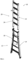
- Figure 1 shows two sections of an extendable ladder. These sections could be half of an MT type ladder or a straight extendable ladder.
- the fixed section such as a base section 12 rests on the ground while the moving section, such as a fly section 20, is adjustable for different heights.
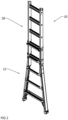
- Figure 2 shows the two sections assembled together with the moving section located within the rails of the fixed section in a typical MT ladder fashion. It is desired that as the moving section is adjusted relative to the fixed section, it can be locked in various positions so that the rungs on the moving section are aligned with the rungs on the fixed section as shown.
- J-locks The typical locks used on MT ladders are known as J-locks.
- the two J-locks must be manually unlocked one at a time, the moving section moved to the desired position, then the J-locks manually locked one at a time.
- J-locks are typically located at the upper end of the fixed section.
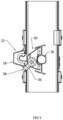
- Figure 3 shows two embodiments of the lock assembly 28 of the present invention.
- the embodiments are shown side by side attached to a rung of the moving section. In reality, only one embodiment would be mounted in the center of the rung.
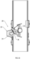
- Figures 4-10 show the operation of the first embodiment.
- a socket 34 is mounted within each of the fixed (base) section rungs.
- a flip lock 36 is attached to one rung of the moving section.
- Figure 4 shows the flip lock 36 in the position to which it returns when free.
- Figure 5 shows the flip lock 36 is deflected as the base rung and fly rung begin to pass each other.
- Figure 6 shows the flip lock 36 as it enters a socket 34.
- Figure 7 shows the flip lock 36 wedged in the socket 34, which prevents the fly rung from further descending.
- Figure 8 shows raising the fly rung withdraws the flip lock 36 from engagement with the socket 34.
- Figure 9 shows the flip lock 36 is returned to its spring-biased position after it has cleared the base rung.
- Figure 10 shows the flip lock 36 deflects from the base rung to allow the fly rung to freely descend.
- a flip lock 36 is attached to one rung of the moving section.
- the flip lock 36 can be pivoted up or down but is biased by spring force to return to the position seen in figure 4 when free. Raising the moving section upward allows the stem 38 of the flip lock 36 to enter the socket 34. At that point, lowering the moving section causes the stem 38 of the flip lock 36 to wedge into the socket 34 ( figures 5-7 ). In this condition, the moving section is prevented from moving downward relative to the fixed section because the size and the shape of the socket 34 prevents the stem 38 from moving in the socket 34. To unlock the moving section, it is raised until the flip lock 36 is above the fixed section rung ( figures 8 and 9 ). At this point, the moving section can be lowered ( figure 10 ) as far as desired.
- the stem 38 when the stem 38 is moving down from above the fixed section rung, the stem 38 is cammed upwards by the fixed section rung as the step moves downward past the fixed section rung, so the stem 38 slides by the socket 34 and does not enter the socket 34. It is only when the stem 38 is moving upwards, and it clears the lower portion of the fixed section rung and is forced under the action of the flip spring 44 back to its stable position can it enter into the socket 34 so that when the stem 38 is now in the socket 34 and the moving section is then lowered, does the stem 38 wedge into the socket 34.
- the upper end of the stem 38, at the bottom is angled inwards to facilitate the movement of the stem 38 out of the socket 34 when the moving section is lifted.
- the shape of the socket 34 is essentially flat along the top of the socket 34 so the stem 38 has essentially no place to move to come out of the socket 34 when a downward force is applied to the stem 38, thus locking the fixed section and the moving section, while the rear of the socket 34 is more rounded to allow the upper and of the stem 38 clearance to come out of the socket 34 when the moving section is lifted.
- Figures 11-17 show the operation of the second embodiment of the lock assembly 28.
- Figure 11 shows the lock 46 and the retractor 48 in the position to which they are spring biased when free of any base rung 18.
- Figure 12 shows the lock 46 is deflected by the base rung 18 as the fly rung 26 is lifted.
- Figure 13 shows the lock 46 has cleared the base rung 18 and the retractor 48 has been partially deflected by the base rung 18.
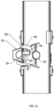
- Figure 14 shows the lock 46 has engaged the base rung 18 to prevent further motion downward as the fly rung 26 has been moved down and the retractor 48 is clear of the base rung 26.
- Figure 15 shows the retractor 48 is deflected by the base rung 18 as the fly rung 26 is lifted and the lock 46 is clear of the base rung 18.
- Figure 16 shows both the lock 46 and the retractor 48 are free and clear of the base rung 18 as the fly rung 26 has been lifted past the base rung 18.
- Figure 17 shows the retractor 48 has fitted into the slot 62 of the lock 46 because the base rung 18 has deflected the retractor 48 as the fly rung 26 is moved down, thus allowing the fly rung 26 to descend freely.
- a lock 46 and a retractor 48 of the lock assembly 28 are attached to one rung 26 of the moving section 20. Both lock 46 and retractor 48 can be pivoted up and down but are biased by spring forces to return to the positions seen in figure 11 .
- Figures 12-14 show the locking sequence which is very similar to embodiment 1. A difference is that when the moving section 20 is locked ( figure 14 ), the lock 46 is braced against the top rear of the fixed section rung 18 by the first arm 58 of the lock 46 extending over the fixed section rung 18 and contacting the top flange 76 of the fixed section rung 18 and the second arm 60 of the lock 46 contacting and pressing against the web 70 of the fixed section rung 18, so this embodiment does not require a socket 34.
- the moving section 20 is prevented from moving downward relative to the fixed section 12 because the lock 46 has nowhere to move with respect to a downward force.
- To unlock the moving section 20 it is raised until both the lock 46 and retractor 48 are above the fixed section rung 18 ( figure 16 ). Then as the moving section 20 is lowered, the first retractor arm 78 of the retractor 48 is cammed upward by the fixed section rung 18 it is moving past, causing the second retractor arm 80 to fit into the slot 62 of the lock 46, which is now free and clear from any fixed section rung 18, and retracts the lock 46 so that the moving section 20 can be lowered ( figure 17 ) as far as desired.
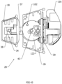
- Figure 18 shows the lock assembly 28 for the first embodiment.
- the flip axle 42 is mounted to the frame 68 and the flip lock 36 is mounted to the flip axle 42.
- the flip stop 73 and the frame stop 72 bias the respective spring as they move, as shown in figures 19-21 .
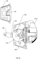
- Figure 19 a cross-sectional side view showing the flip lock stop 74 and the frame stop 72 and the flip lock 36 when the flip lock 36 is free and clear of any base rung 18.
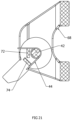
- Figure 20 is a cross-sectional side view of the flip lock 36 when it has been deflected upwards by a base rung 18. The flip lock stop 74 and has pushed against the top of the flip lock spring 64 and the frame stop 72 has maintained the bottom of the flip lock spring 64 in position, thus causing a biasing force by the top of the spring question downwards against the flip lock stop 74.
- Figure 21 is a cross-sectional side view of the flip lock 36 when it has been deflected downwards by a base rung 18. The flip lock stop 74 has pushed against the bottom of the flip lock spring 64 and the frame stop 72 has maintained the top of the flip lock spring 64 in position, thus causing a biasing force by the bottom of the spring upwards against the flip lock 36.
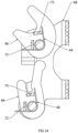
- Figure 22 shows the lock assembly 28 of the second embodiment.
- a frame 68 that is riveted or bolted to the desired rung 26 of the moving section 20.
- a lock axle 50 having the lock 46 mounted to the frame 68 and a retractor axle 54 having the retractor 48 mounted to the frame 68.
- Between the top end and the bottom end of the lock spring 64 is a lock stop 73 and a frame stop 72, and between the top end and the bottom end of the retractor spring 66 is a retractor stop 75 and another frame stop 72.
- Figure 23 is a cross-sectional side view of the lock 46 and the retractor 48 and the frame stops 72 and the lock stop 73 and the retractor stop 75 when the lock 46 and the retractor 48 are free and clear of any base rung 18.
- Figure 24 is a cross-sectional side view of the lock 46 and the retractor 48 when they had been deflected upwards by a base rung 18.
- the lock stop 73 has pushed against the top of the lock spring 64 and the frame stop 72 has maintained the bottom of the lock spring 64 in place, causing a biasing force of the top of the lock spring 64 against the lock stop 73.
- the retractor stop 75 has pushed against the top of the retractor spring 66 and the frame stop 72 has maintained the bottom of the retractor spring 66 in place, causing a biasing force of the top of the retractor spring 66 against the retractor stop 75.
- Figure 25 is a cross-sectional side view of the lock 46 and that retractor 48 when they have been deflected downwards by a base rung 18.
- the lock stop 73 has pushed against the bottom of the lock spring 64 and the frame stop 72 has maintained the top of the lock spring 64 in place, causing a biasing force of the bottom of the lock spring 64 against the lock stop 73.
- the retractor stop 75 has pushed against the bottom of the retractor spring 66 and the frame stop 72 has maintained the top of the retractor spring 66 in place, causing a biasing force at the bottom of the retractor spring 66 against the retractor stop 75.
- the climbing product 10 comprises a base section 12 having a first base rail 14 and a second base rail 16 in parallel and spaced relationship with the first base rail 14 and base rungs 18 attached to and between the first and second base rails 14, 16.
- the climbing product 10 comprises a fly section 20 having a first fly rail 22 and a second fly rail 24 in parallel and spaced relationship with the first fly rail 22 and fly rungs 26 attached to and between the first and second fly rails 22, 24.
- the fly section 20 in sliding engagement with the base section 12.
- the climbing product 10 comprises a lock assembly 28 having a lock fly portion 30 directly attached to the fly section 20.
- the lock fly portion 30 directly engages with the base section 12 to lock the base section 12 with the fly section 20.
- the lock fly portion 30 has a plunger 39. The lock fly portion 30 disengages from the base portion by moving the plunger 39.
- the lock assembly 28 may include a lock base portion 32 directly attached to the base section 12.
- the lock fly portion 30 directly engages with the lock base portion 32 to lock the fly section 20 to the base section 12.
- the lock fly portion 30 disengages from the lock base portion 32 by moving the plunger 39.
- the lock base portion 32 may include a socket 34 disposed in one of the base rungs 18, and the lock fly portion 30 includes a flip lock 36 which fits into the socket 34 to lock the fly section 20 to the base section 12 so the fly section 20 cannot move downwards relative to the base section 12 when the fly section 20 is locked to the base section 12.
- the flip lock 36 disposed in one of the fly rungs 26.
- the flip lock 36 may have a stem 38 which fits into the socket 34 to lock the fly section 20 to the base section 12, an anchor 40 from which the stem 38 extends, a flip axle 42 extending through the anchor 40 about which the anchor 40 with the stem 38 rotates, and a flip spring 44 which biases the stem 38 into a stable position where the stem 38 extends essentially perpendicularly toward the first base rail 14 from the first fly rail 22.
- the flip lock 36 may have a locking recess 120 into which the plunger 39 moves. When the plunger 39 engages the recess, the flip lock 36 is prevented from rotating about its axis.
- the flip lock 36 may include a blocker 122.
- the plunger 39 being able to engage the flip lock 36 to prevent the flip lock's rotation when the blocker 122 is in a first state and does not block the plunger 39 from engaging with the locking recess 120, and the plunger 39 being prevented from engaging the flip lock 36 by the blocking action of the blocker 122 in a second state and the plunger 39 is prevented from engaging with the locking recess 120.
- the lock assembly 28 may include a lock lever 112 engaged with the plunger 39 and a lock lever handle 116 directly connected to the lock lever 112.
- the lock lever handle 116 is moved from its down position to its up position by directly pulling on the lock lever handle 116 which moves the plunger 39 out from the locking recess 120.
- the lock assembly 28 may include a pulley 124 mounted to the lock lever 112, and including a hoist rope 126 which goes around the pulley 124. By increasing tension in the hoist rope 126 the lock lever 112 is moved from its down position to its up position which moves the plunger 39 out from the locking recess 120.
- the present invention pertains to a method for using a ladder whose sections are extendable.
- the method comprises the steps of moving the ladder to a desired position.
- the ladder comprises a base section 12 having a first base rail 14 and a second base rail 16 in parallel and spaced relationship with the first base rail 14 and base rungs 18 attached to and between the first and second base rails 14, 16.
- the ladder comprises a fly section 20 having a first fly rail 22 and a second fly rail 24 in parallel and spaced relationship with the first fly rail 22 and fly rungs 26 attached to and between the first and second fly rails 22, 24.
- the fly section 20 in sliding engagement with the base section 12 the ladder comprises a lock assembly 28 having a lock fly portion 30 directly attached to the fly section 20.
- the lock fly portion 30 directly engages with the base section 12 to lock the base section 12 with the fly section 20.
- the lock fly portion 30 has a plunger 39.
- the lock fly portion 30 disengages from the base portion by moving the plunger 39.
- the present invention pertains to a method for constructing a ladder whose sections are extendable.
- the method comprises the steps of attaching a lock fly portion 30 of the lock assembly 28 directly to a fly section 20 of the ladder.
- the fly section 20 having a first fly rail 22 and a second fly rail 24 in parallel and spaced relationship with the first fly rail 22 and fly rungs 26 attached to and between the first and second fly rails 22, 24.
- the fly section 20 in sliding engagement with the base section 12.
- the lock fly portion 30 has a plunger 39.
- the lock fly portion 30 directly engages with the lock base portion 32 to lock the fly section 20 to the base section 12.
- the lock fly portion 30 disengages from the lock base portion 32 by moving the plunger 39.
- the base section 12 having a first base rail 14 and a second base rail 16 in parallel and spaced relationship with the first base rail 14 and base rungs 18 attached to and between the first and second base rails 14, 16.
- This invention is an additional feature, and an alternative embodiment for the locking assembly with the flip lock 36 described above. This invention prevents inadvertent unlocking of the Extendable Section Lock by requiring a deliberate action by the user. It is an additional feature that, for instance, may be introduced to the apparatus shown in figures 26 - 35 , and 43 - 46 , and described in this application, specifically embodiment 1, thereof.
- This invention prevents the unintended extension of a ladder section, which equates to increased user safety and convenience.
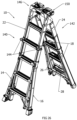
- Figures 26 and 27 show a ladder known as an NGMF (next generation multi form) ladder.
- This ladder can be folded and opened like a step ladder and also be put into a straight ladder configuration like an MT ladder.
- the NGMF has outer sections attached to its front and rear inner sections. These outer sections may be extended relative to the inner sections to increase the height of the ladder.
- the NGMF shown uses conventional J locks on its front section.
- the rear section uses the flip lock 36 invention which is mounted within the lowest rung of the rear inner section.
- Figure 28 is a detail view showing the inner rung with the flip lock 36 engaged with one of the outer rungs. Also shown is a hoisting rope 126 whose function will be described later. There is a hole 161 in the top surface of the flying rung 26 through which the rope 126 extends and wraps around the pulley 124.
- Figure 29 shows just the inner rung with flip lock 36 and an outer rung.
- Figure 30 shows another view of just the inner rung with flip lock 36.
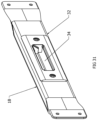
- Figure 31 shows another view of a typical outer rung with a recess for flip lock 36 to engage. These recesses are identical regardless of the length of the particular outer rung.
- Figure 32 shows the components of this invention as seen if the inner rung were transparent. Important to note is that the lock lever pivot 114 and the crank pivot 110 are fixed to the inner rung. The lock lever pivot 114 and the crank pivot 110 can rotate about their respective pivots.
- Figure 33 shows a closeup of figure 32 with some additional components made invisible.
- the key parts of this invention are the flip lock 36, blocker 122, and plunger 39.
- the essence of this invention is the plunger 39 being able to engage the flip lock 36 to prevent its rotation in certain conditions, and, the plunger 39 being prevented from engaging the flip lock 36 by the blocking action of the blocker 122 in other conditions.
- Figure 34 shows the relationship between the flip lock 36 and the blocker 122.
- the blocker 122 pivot is fixed to the flip lock 36.
- the blocker 122 can rotate CCW and CW relative to the flip lock 36.
- the blocker 122 is spring biased towards its extreme CW position as seen in figures 37 , 38 and 39 .
- Figure 35 shows the flip lock 36.
- the flip lock 36 has a locking recess 120 into which the plunger 39 can go. When the plunger 39 engages this recess, the flip lock 36 is prevented from rotating about its axis.
- Figure 36 shows the conditions under which the plunger 39 is able to engage the plunger 39 locking recess 120 in the flip lock 36: the flip lock 36 is horizontal and the blocker 122 is rotated to its extreme CCW position relative to the flip lock 36.
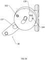
- Figures 37 , 38 and 39 show how the plunger 39 (axis shown by + symbol) is prevented from engaging the plunger 39 locking recess 120 (shown as a dashed line) whenever the blocker 122 is in its extreme CW position relative to the flip lock 36.
- Figures 40 and 41 show the function of the lock lever 112 and the plunger 39.
- the plunger 39 is in its left or engaged position with the locking recess 120. (This assumes that the blocker 122 is not preventing the plunger 39 from entering the plunger 39 locking recess 120 in the flip lock 36.)
- the lock lever 112 is moved from its down position to its up position by the user either directly pulling on the lock lever handle 116 which is directly connected to the lock lever 112, or by increasing the tension in the hoist rope 126 which goes around the pulley 124 mounted on the right end of the lock lever 112.
- Figure 42 shows how the contact between the blocker 122 against the outer rung positions the blocker 122 CCW relative to the flip lock 36 as seen in figure 36 .
- figure 42 shows the only situation in which the blocker 122 allows the plunger 39 to prevent the rotation of the flip lock 36: the flip lock 36 is fully engaged with the recess in outer rung and the lock lever 112 is allowed to move to its down position.
- Figure 43 shows the situation whenever the flip lock 36 is NOT engaged in the recess in an outer rung: the blocker 122 prevents the plunger 39 engaging the flip lock 36 so the flip lock 36 is free to move in the manner of the previously disclosed flip lock 36 invention.
- the flip lock 36 With the plunger 39 completely withdrawn from the flip lock 36, the flip lock 36 is free to rotate about the flip lock axis 106.
- the lock lever pivot 114 moves back down about the lock lever pivot 114, causing the stud 118 to move back away from the crank 108 and the crank 108 to rotate clockwise about the crank pivot 110, which causes the plunger 39 to move forward to try to enter the locking recess 120 again. If the blocker 122 is in the way of the locking recess 120, the blocker 122 prevents the plunger 39 from entering the locking recess 120 and re-engaging with the flip lock 36 to lock the flip lock 36 in place.
- the flip lock 36 When the fly section 20 is locked with the base section 12, the flip lock 36 has its stem 38 in the socket 34 of the desired base rung with respect to the height of the fly section 20 relative to the base section 12. In this event, the plunger 39 is disposed in the locking recess 120 preventing the flip lock 36 from being able to rotate, as shown in figure 36 and figure 42 , and thus preventing the flip lock 36 from coming out of the locking recess 120 and consequently preventing the fly section 20 moving relative to the base section 12.
- the nose 137 of the blocker 122 is no longer displaced by the base rung, and the blocker 122 is biased back to its stable position by the flip lock spring, causing the blocker 122 to rotate clockwise about the blocker pivot 102 over the locking recess 120 so the plunger 39 cannot slide into the locking recess 120, as shown in figure 43 , because the plunger axis 104 of the plunger 39 that aligns with the locking recess is blocked by the blocker 122.
- the flip lock spring biases the blocker 122 into a position that blocks the plunger 39 from sliding into the locking recess 120.
- the fly section 20 is prevented by the flip lock 36 inserted in the socket 34 to be moved directly down. This is because the top surface of the stem 38 is flat, so when the fly section 20 is moved down, the top surface of the stem 38 hits the top of the socket 34 and has nowhere to go, as explained above in regard to the first embodiment of the flip lock 36. In this instance, the flip lock 36 cannot slide out of the socket 34. Accordingly, only when the fly section 20 is lifted upwards, can the flip lock 36 withdraw from the socket 34, and the plunger 39 has been withdrawn.
- the fly section 20 can be moved downward. As the fly section 20 moves down, the flip lock 36 and the nose 137 strike the top of the base rung and are deflected upwards, as shown in figure 38 . It should be noted that the blocker 122 pivots forward CW about the blocker 122 pivot and the flip lock axle moves to the rightmost position of the blocker slot 139 because the nose 137 is no longer being deflected by the base rung.
- the stem 38 of the flip lock 36 slides past the socket 34 of the base rung and continues moving down until it clears the base rung, where the flip lock 36 and the blocker 122 will revert to the position shown in figure 37 .
- the stem 38 of the flip lock 36 and the nose 137 of the blocker 122 will strike the bottom of the base rung in the deflected downwards by the base rung, as shown in figure 39 .
- the stem 38 and the nose 137 will move past the socket 34 of the base rung and continue upwards until the flip lock 36 and the blocker 122 cleared the base rung, whereupon they will revert back to the position shown in figure 37 .
- fly rung 26 Only one fly rung 26 has the flip lock 36 and blocker 122 arrangements, but at least some if not all of the base rungs 18 will have a socket 34 so the fly section 20 can be positioned at a desired height relative to the base section 12 by having the flip lock 36 for the into the desired socket 34.
- the fly section 20 is moved down slightly so the stem 38 of the flip lock 36 slides fully into the socket 34 and the nose 137 of the blocker 122 is deflected downwards by the base rung and takes the position shown in figure 36 .
- the configuration of figure 36 has the blocker 122 opening now aligned with the locking recess 120, so the plunger 39 now slides into the locking recess 120 and engages with the flip lock 36, to lock the flip lock 36 in place with the socket 34 of the base rung.
- Figure 44 shows the routing of the hoist rope 126 between the base section 12 and the fly section 20.
- a first end 152 of the rope 126 is attached to the top of the outer/base section 12 of the rear section 142. From there, the rope 126 extends down the base rail of the rear section 142, where the rope 126 passes around the pulley 124 on the lock lever 112. From there, the rope 126 extends along the base rail and the fly rail above the base rail to the hinge 148 where it is routed to the front section 140.
- At the front section 140 extends down along the fly rail of the front section 140 to the base rail below the fly rail of the front section 140 where the second end 154 of the rope 126 is attached to the lowest fly rung 26 on the inner/fly section 20 of the front section 140.
- Figure 45 shows the ladder in the fully extended straight extension ladder position from the non-climbing side.
- Figure 46 shows the ladder in the fully extended straight extension ladder position from the climbing side.
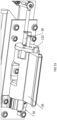
- Figures 47A-47E show multiple views of the lock lever 112 and lock lever handle 116 in place on the fly rung 26.
- the lock lever 112 and lock lever handle 116 are mounted external to the back wall 120 of the fly rung 26.
- the pulley 124 on the lock lever 112 however intrudes into the interior of the fly rung 26.
- Figure 47A is a perspective view of the top of the fly rung 26 and lock assembly 28.
- Figure 47B is a rightside view of the fly rung 26 and lock assembly 28.
- Figure 47C it is a backside/right side view of the fly rung 26 and lock assembly 28.
- Figure 47D is a top view of the fly rung 26 and lock assembly 28.
- Figure 47E is a front side, upside down of the fly rung 26 and lock assembly 28.
- Figure 47F is a left side view of the fly rung 26 and lock assembly 28. As can be seen from these figures, the lock assembly 28 essentially fits within and is protected by the fly rung 26. The flip lock 36 and the handle 116 of the lock assembly 28 are basically the only components which extend beyond the fly rung 26.
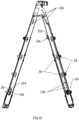
- Figure 48 is a perspective view of the ladder with the fly sections extended.
- Figure 49 is a perspective view of the flip lock 36 with the blocker 122 and the flip lock spring 145, which biases the blocker 122, in place in the flip lock 36 and adjacent the blocker 122.
- the ladder 10 may be a standard extension ladder having a fly section 20 and a base section 12.
- the ladder 10 may be a multipurpose ladder having a front section 140 and a rear section 142, as shown in figure 26 and figure 27 in an unextended step ladder configuration, or figure 48 in an extended step ladder configuration, or in figures 45 and 46 in an unextended extension ladder configuration.
- the front section may have J locks 144 for locking the fly section 20 and the base section 12 together at a desired length, and the rear section 142 having the lock assembly 28 described herein for locking the fly section 20 and the base section 12 of the rear section 142 at a desired length.
- the front section 140 instead of having J locks 144, may use the lock assembly 28 for locking the fly section 20 and base section 12 together.
- the front section 140 also has a base section 12 having a first base rail 14 and a second base rail 16 with base rungs 18 attached to them and disposed between them, as described above regarding the base section 12 and the fly section 20.
- the front section 140 also has a fly section 20 having a first fly rail 22 and a second fly rail 24 with fly rungs 26 attached to them and disposed between them, as described above regarding the base section 12 and the fly section 20.
- the base rungs 18 attached to the outside flanges of the first and second base rails, and the fly rungs 26 are attached to the inside of the web of the first and second fly rails so as not to interfere with the movement of the fly section 20 relative to the base section 12.
- the first and second fly rails of the front section are attached with rivets or fasteners to a ladder top 146.
- Hinges 148 are attached by rivets or fasteners to the first and second fly rails of the front section adjacent the ladder top 146.
- the tops of the fly rails of the rear section 142 are attached to the hinges 148.
- the hinges 148 allow the rear section 142 to rotate relative to the front section 140. As shown in figures 20 and 21 , the rear section 142 has rotated about 180° relative to the front section 142 form the extension ladder position.
- the first fly rail 22 of the rear section 142 and the second fly rail 24 of the rear section 142 fit into channels 150 in the ladder top 146 to allow the rear section 142 to align with the front section 140, although slightly offset due to the connection of the rear section fly rails being attached to the hinges 148.
Landscapes
- Engineering & Computer Science (AREA)
- Mechanical Engineering (AREA)
- Ladders (AREA)
- Handcart (AREA)
Description
- The present invention pertains to a climbing product having an extendable section lock assembly. (As used herein, references to the "present invention" or "invention" relate to exemplary embodiments and not necessarily to every embodiment encompassed by the appended claims.) More specifically, the present invention pertains to a climbing product having an extendable section lock assembly where the lock assembly includes a fly lock portion attached to a fly section of the climbing product which locks with a base section of the climbing product, and which unlocks from the base section simply by the fly section being lifted relative to the base section.
- This section is intended to introduce the reader to various aspects of the art that may be related to various aspects of the present invention. The following discussion is intended to provide information to facilitate a better understanding of the present invention. Accordingly, it should be understood that statements in the following discussion are to be read in this light, and not as admissions of prior art.
- Current locking systems for extendable ladders and other devices with extendable sections require the user to perform a separate action to unlock the extendable sections prior to moving them. The performance of a separate action to unlock the extendable sections can be burdensome and introduce possible error that could cause the extendable sections to move relative to each other in an undesired manner, resulting in damage or injury. It would be desirable to eliminate the need to perform a separate action to unlock the extendable sections prior to moving.
- In addition, current locking systems on extension ladders are large and intrusive into a user's working space. It would be desirable to reduce or eliminate intrusion of a locking system into the user's working space.
- Document
US 5 000 289 A discloses a folding step ladder composed of four ladder elements:
an upper-front element joined to an upper-rear element at a top hinge-step, a lower-front element slidingly joined to the upper-front element along its length, and a lower-rear element slidingly joined to the upper-rear element along its length. The lower elements captively slide along the length of their corresponding upper element and are capable of being held at a particular incremental extension by a latch arrangement that engages the upper element when downward force is exerted on the ladder. - The present invention pertains to a climbing product as set out in claim 1 below.
- The present invention pertains to a method for using a climbing product as set out in claim 7 below.
- The present invention pertains to a method for producing a climbing product as set out in claim 8 below.
-
-
Figure 1 shows two sections of an extendable ladder. -
Figure 2 shows the two sections assembled together with the moving section located within the rails of the fixed section in a typical MT ladder fashion. -
Figure 3 shows two embodiments of the lock assembly of the present invention. -
Figure 4 shows the flip lock in the position to which it returns when free. -
Figure 5 shows the flip lock is deflected as the base rung and fly rung begin to pass each other. -
Figure 6 shows the flip lock as it enters a socket. -
Figure 7 shows the flip lock wedged in the socket, which prevents the fly rung from further descending. -
Figure 8 shows raising the fly rung withdraws the flip lock from engagement with the socket. -
Figure 9 shows the flip lock is returned to its spring-biased position after it has cleared the base rung. -
Figure 10 shows the flip lock deflects from the base rung to allow the fly rung to freely descend. -
Figure 11 shows the lock and the retractor in the position to which they are spring biased when free of any base rung. -
Figure 12 shows the lock is deflected by the base rung as the fly rung is lifted. -
Figure 13 shows the lock has cleared the base rung in the retractor has been partially deflected by the base rung. -
Figure 14 shows the lock has engage the base rung to prevent further motion downward as the fly rung has been moved down and the retractor is clear of the base rung. -
Figure 15 shows the retractor is deflected by the base rung as the fly rung is lifted and the lock is clear of the base rung. -
Figure 16 shows both the lock and the retractor are free and clear of the base rung as the fly rung has been lifted past the base rung. -
Figure 17 shows the retractor has fitted into the slot of the lock because the base rung has deflected the retractor as the fly rung is moved down, thus allowing the fly rung to the sender freely. -
Figure 18 shows the lock assembly for the first embodiment. -
Figure 19 a cross-sectional side view showing the flip lock stop and the frame stop and the flip lock when the flip lock is free and clear of any base rung. -
Figure 20 is a cross-sectional side view of the flip lock when it has been deflected upwards by a base rung. -
Figure 21 is a cross-sectional side view of the flip lock when it has been deflected downwards by a base rung. -
Figure 22 shows the lock assembly of the second embodiment. -
Figure 23 is a cross-sectional side view of the lock in the retractor and the frame stops and the lock stop and the retractor stop when the lock and the retractor are free and clear of any base rung. -
Figure 24 is a cross-sectional side view of the lock and the retractor when they had been deflected upwards by a base rung. -
Figure 25 is a cross-sectional side view of the lock and that retractor when they have been deflected downwards by a base rung. -
Figures 26 and27 show a ladder known as an NGMF (next generation multi form) ladder. -
Figure 28 is a detail view showing the inner rung with the flip lock engaged with one of the outer rungs. -
Figure 29 shows just the inner rung with flip lock and an outer rung. -
Figure 30 shows another view of just the inner rung with flip lock. -
Figure 31 shows another view of a typical outer rung with a recess for the flip lock to engage. -
Figure 32 shows the components of this invention as seen if the inner rung were transparent. -
Figure 33 shows a closeup offigure 32 with some additional components made invisible. The key parts of this invention are the flip lock, blocker, and plunger. -
Figure 34 shows the relationship between the flip lock and the blocker. -
Figure 35 shows the flip lock. -
Figure 36 shows the conditions under which the plunger is able to engage the plunger locking recess in the flip lock: the flip lock is horizontal and the blocker is rotated to its extreme CCW position relative to the flip lock. -
Figures 37 ,38 and39 show how the plunger (axis shown by + symbol) is prevented from engaging the plunger locking recess (shown as a dashed line) whenever the blocker is in its extreme CW position relative to the flip lock. -
Figures 40 and41 show the function of the lock lever and the plunger. When the right end of the lock lever is down as infigure 40 , the plunger is in its left or engaged position with the locking recess. When the right end of the lever is lifted as infigure 41 , the plunger is moved to its right or disengaged position from the locking recess. -
Figure 42 shows how the contact between the blocker against the outer rung positions the blocker CCW relative to the flip lock as seen infigure 36 . -
Figure 43 shows the situation whenever the flip lock is NOT engaged in the recess in an outer rung: the blocker prevents the plunger engaging the flip lock so the flip lock is free to move in the manner of the previously disclosed flip lock invention. -
Figure 44 shows the routing of the hoist rope between the base section and the fly section. -
Figure 45 shows the ladder in the fully extended straight extension ladder position from the non-climbing side. -
Figure 46 shows the ladder in the fully extended straight extension ladder position from the climbing side. -
Figures 47A- 47E show multiple views of the lock lever and lock lever handle in place on the rung. -
Figure 48 is a perspective view of the ladder with the fly sections extended. -
Figure 49 is a perspective view of the flip lock with the blocker and the flip lock spring, which biases the blocker, in place in the flip lock and adjacent the blocker. - Referring now to the drawings wherein like reference numerals refer to similar or identical parts throughout the several views, and more specifically to
figures 1-3 thereof, there is shown a climbing product whose sections are extendable. The climbing product comprises abase section 12 having afirst base rail 14 and asecond base rail 16 in parallel and spaced relationship with thefirst base rail 14 andbase rungs 18 attached to and between the first and second base rails 14, 16. The climbing product comprises afly section 20 having afirst fly rail 22 and asecond fly rail 24 in parallel and spaced relationship with thefirst fly rail 22 and flyrungs 26 attached to and between the first and second fly rails 22, 24. Thefly section 20 in sliding engagement with thebase section 12. The climbing product comprises alock assembly 28 having alock fly portion 30 directly attached to thefly section 20. Thelock fly portion 30 directly engages with thebase section 12 to lock thebase section 12 with thefly section 20. Thelock fly portion 30 disengages from thelock base portion 32 by simply moving thefly section 20 relative to thebase section 12 to unlock thefly section 20 from thebase section 12. The climbingproduct 10 may include but not be limited to MT ladders, leaning ladders, and work platforms. - The
lock assembly 28 may include alock base portion 32 directly attached to thebase section 12, as shown infigures 3-10 and18-21 . Thelock fly portion 30 directly engages with thelock base portion 32 to lock thefly section 20 to thebase section 12. Thelock fly portion 30 disengages from thelock base portion 32 by simply moving thefly section 20 relative to thebase section 12 to unlock thefly section 20 from thebase section 12. Thelock base portion 32 may include asocket 34 disposed in one of thebase rungs 18, and thelock fly portion 30 includes aflip lock 36 which fits into thesocket 34 to lock thefly section 20 to thebase section 12 so thefly section 20 cannot move downwards relative to thebase section 12 when thefly section 20 is locked to thebase section 12. Theflip lock 36 disposed in one of thefly rungs 26. Theflip lock 36 may have astem 38 which fits into thesocket 34 to lock thefly section 20 to thebase section 12, ananchor 40 from which thestem 38 extends, aflip axle 42 extending through theanchor 40 about which theanchor 40 with thestem 38 rotates, and aflip spring 44 which biases thestem 38 into a stable position where thestem 38 extends essentially perpendicularly toward thefirst base rail 14 from thefirst fly rail 22. - The
lock fly portion 30 may include alock 46 which directly engages with one of thebase rungs 18 to lock thefly section 20 to thebase section 12 so thefly section 20 cannot move downwards relative to thebase section 12 when thefly section 20 is locked to thebase section 12. Seefigures 11-17 and22-25 . Thelock fly portion 30 disengages from thelock base portion 32 by simply moving thefly section 20 relative to thebase section 12 to unlock thefly section 20 from thebase section 12. Thelock fly portion 30 may include aretractor 48 disposed adjacent thelock 46 which engages thelock 46 and maintains thelock 46 in a position out of the way of thebase rungs 18 as thefly section 20 is moved downwards relative to thebase section 12. Thelock fly portion 30 may have alock axle 50 extending through thelock 46 about which thelock 46 rotates and aretractor axle 54 extending through theretractor 48 about which theretractor 48 rotates. Thelock 46 may have ananchor 40, afirst arm 58 extending from theanchor 40 and asecond arm 60 which is in spaced relation with thefirst arm 58, where thefirst arm 58 is longer than thesecond arm 60 and where thesecond arm 60 extends from theanchor 40. Thefirst arm 58 and thesecond arm 60 and theanchor 40 together formed essentially a C shape and define aslot 62 between thefirst arm 58 and thesecond arm 60. Thelock fly portion 30 may include alock spring 64 which biases thelock 46 into a stable position where thefirst arm 58 andsecond arm 60 extend toward thefirst base rail 14. Thelock fly portion 30 includes aretractor spring 66 which biases theretractor 48 into a stable position where theretractor 48 extends toward thefirst base rail 14. - The present invention pertains to a method for using a climbing
product 10 whose sections are extendable. The method comprises the steps of sliding afly section 20 of the climbingproduct 10 relative to abase section 12 of the climbingproduct 10 to which thefly section 20 is in sliding engagement. There is the step of locking thefly section 20 to thebase section 12. There is the step of lifting thefly section 20 relative to thebase section 12 to unlock thefly section 20 from thebase section 12. There is the step of moving thefly section 20 down relative to thebase section 12. - The present invention pertains to a method for producing a climbing
product 10 whose sections are extendable. The method comprises the steps of attaching alock assembly 28 having alock fly portion 30 directly to a rung of afly section 20 of the climbingproduct 10. There is the step of sliding thefly section 20 along abase section 12 of the climbingproduct 10 so thefly section 20 engages with thebase section 12. - In the operation of the invention, the
lock assembly 28 allows for extendable sections to be moved and locked without the need to reach a locking mechanism, such as when extending and retracting the top section of an MT ladder when set up in extension mode. Furthermore, thelock assembly 28 provides for reduced or eliminated intrusion into the user's working space by being positioned mostly in or under rungs of the climbingproduct 10. -
Figure 1 shows two sections of an extendable ladder. These sections could be half of an MT type ladder or a straight extendable ladder. The fixed section, such as abase section 12, rests on the ground while the moving section, such as afly section 20, is adjustable for different heights. -
Figure 2 shows the two sections assembled together with the moving section located within the rails of the fixed section in a typical MT ladder fashion. It is desired that as the moving section is adjusted relative to the fixed section, it can be locked in various positions so that the rungs on the moving section are aligned with the rungs on the fixed section as shown. - The typical locks used on MT ladders are known as J-locks. The two J-locks must be manually unlocked one at a time, the moving section moved to the desired position, then the J-locks manually locked one at a time. J-locks are typically located at the upper end of the fixed section.
-
Figure 3 shows two embodiments of thelock assembly 28 of the present invention. Infigure 3 , the embodiments are shown side by side attached to a rung of the moving section. In reality, only one embodiment would be mounted in the center of the rung. -
Figures 4-10 show the operation of the first embodiment. Asocket 34 is mounted within each of the fixed (base) section rungs. Aflip lock 36 is attached to one rung of the moving section.Figure 4 shows theflip lock 36 in the position to which it returns when free.Figure 5 shows theflip lock 36 is deflected as the base rung and fly rung begin to pass each other.Figure 6 shows theflip lock 36 as it enters asocket 34.Figure 7 shows theflip lock 36 wedged in thesocket 34, which prevents the fly rung from further descending.Figure 8 shows raising the fly rung withdraws theflip lock 36 from engagement with thesocket 34.Figure 9 shows theflip lock 36 is returned to its spring-biased position after it has cleared the base rung.Figure 10 shows theflip lock 36 deflects from the base rung to allow the fly rung to freely descend. - A
flip lock 36 is attached to one rung of the moving section. Theflip lock 36 can be pivoted up or down but is biased by spring force to return to the position seen infigure 4 when free. Raising the moving section upward allows thestem 38 of theflip lock 36 to enter thesocket 34. At that point, lowering the moving section causes thestem 38 of theflip lock 36 to wedge into the socket 34 (figures 5-7 ). In this condition, the moving section is prevented from moving downward relative to the fixed section because the size and the shape of thesocket 34 prevents thestem 38 from moving in thesocket 34. To unlock the moving section, it is raised until theflip lock 36 is above the fixed section rung (figures 8 and9 ). At this point, the moving section can be lowered (figure 10 ) as far as desired. It should be noted that when thestem 38 is moving down from above the fixed section rung, thestem 38 is cammed upwards by the fixed section rung as the step moves downward past the fixed section rung, so thestem 38 slides by thesocket 34 and does not enter thesocket 34. It is only when thestem 38 is moving upwards, and it clears the lower portion of the fixed section rung and is forced under the action of theflip spring 44 back to its stable position can it enter into thesocket 34 so that when thestem 38 is now in thesocket 34 and the moving section is then lowered, does thestem 38 wedge into thesocket 34. The upper end of thestem 38, at the bottom is angled inwards to facilitate the movement of thestem 38 out of thesocket 34 when the moving section is lifted. The shape of thesocket 34 is essentially flat along the top of thesocket 34 so thestem 38 has essentially no place to move to come out of thesocket 34 when a downward force is applied to thestem 38, thus locking the fixed section and the moving section, while the rear of thesocket 34 is more rounded to allow the upper and of thestem 38 clearance to come out of thesocket 34 when the moving section is lifted. -
Figures 11-17 show the operation of the second embodiment of thelock assembly 28.Figure 11 shows thelock 46 and theretractor 48 in the position to which they are spring biased when free of anybase rung 18.Figure 12 shows thelock 46 is deflected by the base rung 18 as the fly rung 26 is lifted.Figure 13 shows thelock 46 has cleared thebase rung 18 and theretractor 48 has been partially deflected by thebase rung 18.Figure 14 shows thelock 46 has engaged the base rung 18 to prevent further motion downward as the fly rung 26 has been moved down and theretractor 48 is clear of thebase rung 26.Figure 15 shows theretractor 48 is deflected by the base rung 18 as the fly rung 26 is lifted and thelock 46 is clear of thebase rung 18.Figure 16 shows both thelock 46 and theretractor 48 are free and clear of the base rung 18 as the fly rung 26 has been lifted past thebase rung 18.Figure 17 shows theretractor 48 has fitted into theslot 62 of thelock 46 because the base rung 18 has deflected theretractor 48 as the fly rung 26 is moved down, thus allowing the fly rung 26 to descend freely. - A
lock 46 and aretractor 48 of thelock assembly 28 are attached to onerung 26 of the movingsection 20. Both lock 46 andretractor 48 can be pivoted up and down but are biased by spring forces to return to the positions seen infigure 11 .Figures 12-14 show the locking sequence which is very similar to embodiment 1. A difference is that when the movingsection 20 is locked (figure 14 ), thelock 46 is braced against the top rear of the fixedsection rung 18 by thefirst arm 58 of thelock 46 extending over the fixedsection rung 18 and contacting thetop flange 76 of the fixedsection rung 18 and thesecond arm 60 of thelock 46 contacting and pressing against theweb 70 of the fixedsection rung 18, so this embodiment does not require asocket 34. In this condition, the movingsection 20 is prevented from moving downward relative to the fixedsection 12 because thelock 46 has nowhere to move with respect to a downward force. To unlock the movingsection 20, it is raised until both thelock 46 andretractor 48 are above the fixed section rung 18 (figure 16 ). Then as the movingsection 20 is lowered, thefirst retractor arm 78 of theretractor 48 is cammed upward by the fixedsection rung 18 it is moving past, causing thesecond retractor arm 80 to fit into theslot 62 of thelock 46, which is now free and clear from any fixedsection rung 18, and retracts thelock 46 so that the movingsection 20 can be lowered (figure 17 ) as far as desired. Once the lowering of the movingsection 20 has stopped, under the action of theretractor spring 66 and thelock spring 64 of theretractor 48 and thelock 46, respectively, theretractor 48 and thelock 46 will return to their stable positions as long as there is no fixedsection rung 18 blocking them. -
Figure 18 shows thelock assembly 28 for the first embodiment. There is aframe 68 that is riveted or bolted to the desiredrung 26 of the movingsection 20. Theflip axle 42 is mounted to theframe 68 and theflip lock 36 is mounted to theflip axle 42. There is aflip spring 44 positioned about theflip axle 42 with a top end and a bottom end of theflip spring 44 extending outwards. Between the top end and the bottom end of theflip spring 44 is aflip stop 73 extending from theflip lock 36 and aframe stop 72 extending from theframe 68. Theflip stop 73 and theframe stop 72 bias the respective spring as they move, as shown infigures 19-21 . -
Figure 19 a cross-sectional side view showing theflip lock stop 74 and theframe stop 72 and theflip lock 36 when theflip lock 36 is free and clear of anybase rung 18.Figure 20 is a cross-sectional side view of theflip lock 36 when it has been deflected upwards by abase rung 18. Theflip lock stop 74 and has pushed against the top of theflip lock spring 64 and theframe stop 72 has maintained the bottom of theflip lock spring 64 in position, thus causing a biasing force by the top of the spring question downwards against theflip lock stop 74.Figure 21 is a cross-sectional side view of theflip lock 36 when it has been deflected downwards by abase rung 18. Theflip lock stop 74 has pushed against the bottom of theflip lock spring 64 and theframe stop 72 has maintained the top of theflip lock spring 64 in position, thus causing a biasing force by the bottom of the spring upwards against theflip lock 36. -
Figure 22 shows thelock assembly 28 of the second embodiment. There is aframe 68 that is riveted or bolted to the desiredrung 26 of the movingsection 20. There is alock axle 50 having thelock 46 mounted to theframe 68 and aretractor axle 54 having theretractor 48 mounted to theframe 68. There is alock spring 64 positioned about thelock axle 50 and aretractor spring 66 positioned about theretractor axle 54. Between the top end and the bottom end of thelock spring 64 is alock stop 73 and aframe stop 72, and between the top end and the bottom end of theretractor spring 66 is aretractor stop 75 and anotherframe stop 72. - The frame stops 72 and the
lock stop 73 and theretractor stop 75 bias the respective springs as they move, as shown infigures 22-25 .Figure 23 is a cross-sectional side view of thelock 46 and theretractor 48 and the frame stops 72 and thelock stop 73 and theretractor stop 75 when thelock 46 and theretractor 48 are free and clear of anybase rung 18. -
Figure 24 is a cross-sectional side view of thelock 46 and theretractor 48 when they had been deflected upwards by abase rung 18. Thelock stop 73 has pushed against the top of thelock spring 64 and theframe stop 72 has maintained the bottom of thelock spring 64 in place, causing a biasing force of the top of thelock spring 64 against thelock stop 73. Similarly, theretractor stop 75 has pushed against the top of theretractor spring 66 and theframe stop 72 has maintained the bottom of theretractor spring 66 in place, causing a biasing force of the top of theretractor spring 66 against theretractor stop 75. -
Figure 25 is a cross-sectional side view of thelock 46 and thatretractor 48 when they have been deflected downwards by abase rung 18. Thelock stop 73 has pushed against the bottom of thelock spring 64 and theframe stop 72 has maintained the top of thelock spring 64 in place, causing a biasing force of the bottom of thelock spring 64 against thelock stop 73. Similarly, theretractor stop 75 has pushed against the bottom of theretractor spring 66 and theframe stop 72 has maintained the top of theretractor spring 66 in place, causing a biasing force at the bottom of theretractor spring 66 against theretractor stop 75. - Referring now to the drawings wherein like reference numerals refer to similar or identical parts throughout the several views, and more specifically to
figures 26 - 33 thereof, there is shown a climbingproduct 10 whose sections are extendable. The climbingproduct 10 comprises abase section 12 having afirst base rail 14 and asecond base rail 16 in parallel and spaced relationship with thefirst base rail 14 andbase rungs 18 attached to and between the first and second base rails 14, 16. The climbingproduct 10 comprises afly section 20 having afirst fly rail 22 and asecond fly rail 24 in parallel and spaced relationship with thefirst fly rail 22 and flyrungs 26 attached to and between the first and second fly rails 22, 24. Thefly section 20 in sliding engagement with thebase section 12. The climbingproduct 10 comprises alock assembly 28 having alock fly portion 30 directly attached to thefly section 20. Thelock fly portion 30 directly engages with thebase section 12 to lock thebase section 12 with thefly section 20. Thelock fly portion 30 has aplunger 39. Thelock fly portion 30 disengages from the base portion by moving theplunger 39. - The
lock assembly 28 may include alock base portion 32 directly attached to thebase section 12. Thelock fly portion 30 directly engages with thelock base portion 32 to lock thefly section 20 to thebase section 12. Thelock fly portion 30 disengages from thelock base portion 32 by moving theplunger 39. Thelock base portion 32 may include asocket 34 disposed in one of thebase rungs 18, and thelock fly portion 30 includes aflip lock 36 which fits into thesocket 34 to lock thefly section 20 to thebase section 12 so thefly section 20 cannot move downwards relative to thebase section 12 when thefly section 20 is locked to thebase section 12. Theflip lock 36 disposed in one of thefly rungs 26. - The
flip lock 36 may have astem 38 which fits into thesocket 34 to lock thefly section 20 to thebase section 12, ananchor 40 from which thestem 38 extends, aflip axle 42 extending through theanchor 40 about which theanchor 40 with thestem 38 rotates, and aflip spring 44 which biases thestem 38 into a stable position where thestem 38 extends essentially perpendicularly toward thefirst base rail 14 from thefirst fly rail 22. Theflip lock 36 may have alocking recess 120 into which theplunger 39 moves. When theplunger 39 engages the recess, theflip lock 36 is prevented from rotating about its axis. Theflip lock 36 may include ablocker 122. Theplunger 39 being able to engage theflip lock 36 to prevent the flip lock's rotation when theblocker 122 is in a first state and does not block theplunger 39 from engaging with thelocking recess 120, and theplunger 39 being prevented from engaging theflip lock 36 by the blocking action of theblocker 122 in a second state and theplunger 39 is prevented from engaging with thelocking recess 120. - The
lock assembly 28 may include alock lever 112 engaged with theplunger 39 and a lock lever handle 116 directly connected to thelock lever 112. Thelock lever handle 116 is moved from its down position to its up position by directly pulling on the lock lever handle 116 which moves theplunger 39 out from the lockingrecess 120. Thelock assembly 28 may include apulley 124 mounted to thelock lever 112, and including a hoistrope 126 which goes around thepulley 124. By increasing tension in the hoistrope 126 thelock lever 112 is moved from its down position to its up position which moves theplunger 39 out from the lockingrecess 120. - The present invention pertains to a method for using a ladder whose sections are extendable. The method comprises the steps of moving the ladder to a desired position. The ladder comprises a
base section 12 having afirst base rail 14 and asecond base rail 16 in parallel and spaced relationship with thefirst base rail 14 andbase rungs 18 attached to and between the first and second base rails 14, 16. The ladder comprises afly section 20 having afirst fly rail 22 and asecond fly rail 24 in parallel and spaced relationship with thefirst fly rail 22 and flyrungs 26 attached to and between the first and second fly rails 22, 24. Thefly section 20 in sliding engagement with thebase section 12 the ladder comprises alock assembly 28 having alock fly portion 30 directly attached to thefly section 20. Thelock fly portion 30 directly engages with thebase section 12 to lock thebase section 12 with thefly section 20. Thelock fly portion 30 has aplunger 39. Thelock fly portion 30 disengages from the base portion by moving theplunger 39. There is the step of moving theplunger 39 so thelock fly portion 30 disengages from base portion. There is the step of sliding thefly section 20 along thebase section 12 to extend the ladder to a desired length. There is the step of locking thefly section 20 to thebase section 12 with the lock portion at the desired length. - The present invention pertains to a method for constructing a ladder whose sections are extendable. The method comprises the steps of attaching a
lock fly portion 30 of thelock assembly 28 directly to afly section 20 of the ladder. Thefly section 20 having afirst fly rail 22 and asecond fly rail 24 in parallel and spaced relationship with thefirst fly rail 22 and flyrungs 26 attached to and between the first and second fly rails 22, 24. Thefly section 20 in sliding engagement with thebase section 12. Thelock fly portion 30 has aplunger 39. There is the step of attaching alock base portion 32 of thelock assembly 28 directly attached to thebase section 12. Thelock fly portion 30 directly engages with thelock base portion 32 to lock thefly section 20 to thebase section 12. Thelock fly portion 30 disengages from thelock base portion 32 by moving theplunger 39. Thebase section 12 having afirst base rail 14 and asecond base rail 16 in parallel and spaced relationship with thefirst base rail 14 andbase rungs 18 attached to and between the first and second base rails 14, 16. - This invention is an additional feature, and an alternative embodiment for the locking assembly with the
flip lock 36 described above. This invention prevents inadvertent unlocking of the Extendable Section Lock by requiring a deliberate action by the user. It is an additional feature that, for instance, may be introduced to the apparatus shown infigures 26 - 35 , and43 - 46 , and described in this application, specifically embodiment 1, thereof. - This invention prevents the unintended extension of a ladder section, which equates to increased user safety and convenience.
-
Figures 26 and27 show a ladder known as an NGMF (next generation multi form) ladder. This ladder can be folded and opened like a step ladder and also be put into a straight ladder configuration like an MT ladder. Also like an MT ladder, the NGMF has outer sections attached to its front and rear inner sections. These outer sections may be extended relative to the inner sections to increase the height of the ladder. The NGMF shown uses conventional J locks on its front section. The rear section uses theflip lock 36 invention which is mounted within the lowest rung of the rear inner section. -
Figure 28 is a detail view showing the inner rung with theflip lock 36 engaged with one of the outer rungs. Also shown is a hoistingrope 126 whose function will be described later. There is ahole 161 in the top surface of the flyingrung 26 through which therope 126 extends and wraps around thepulley 124. -
Figure 29 shows just the inner rung withflip lock 36 and an outer rung. -
Figure 30 shows another view of just the inner rung withflip lock 36. -
Figure 31 shows another view of a typical outer rung with a recess forflip lock 36 to engage. These recesses are identical regardless of the length of the particular outer rung. -
Figure 32 shows the components of this invention as seen if the inner rung were transparent. Important to note is that thelock lever pivot 114 and thecrank pivot 110 are fixed to the inner rung. Thelock lever pivot 114 and thecrank pivot 110 can rotate about their respective pivots. -
Figure 33 shows a closeup offigure 32 with some additional components made invisible. The key parts of this invention are theflip lock 36,blocker 122, andplunger 39. The essence of this invention is theplunger 39 being able to engage theflip lock 36 to prevent its rotation in certain conditions, and, theplunger 39 being prevented from engaging theflip lock 36 by the blocking action of theblocker 122 in other conditions. -
Figure 34 shows the relationship between theflip lock 36 and theblocker 122. Theblocker 122 pivot is fixed to theflip lock 36. Theblocker 122 can rotate CCW and CW relative to theflip lock 36. Theblocker 122 is spring biased towards its extreme CW position as seen infigures 37 ,38 and39 . -
Figure 35 shows theflip lock 36. Theflip lock 36 has alocking recess 120 into which theplunger 39 can go. When theplunger 39 engages this recess, theflip lock 36 is prevented from rotating about its axis. -
Figure 36 shows the conditions under which theplunger 39 is able to engage theplunger 39locking recess 120 in the flip lock 36: theflip lock 36 is horizontal and theblocker 122 is rotated to its extreme CCW position relative to theflip lock 36. -
Figures 37 ,38 and39 show how the plunger 39 (axis shown by + symbol) is prevented from engaging theplunger 39 locking recess 120 (shown as a dashed line) whenever theblocker 122 is in its extreme CW position relative to theflip lock 36. -
Figures 40 and41 show the function of thelock lever 112 and theplunger 39. When the right end of thelock lever 112 is down as infigure 40 , theplunger 39 is in its left or engaged position with thelocking recess 120. (This assumes that theblocker 122 is not preventing theplunger 39 from entering theplunger 39locking recess 120 in theflip lock 36.) - When the right end of the lever is lifted as in
figure 41 , theplunger 39 is moved to its right or disengaged position from the lockingrecess 120. Theplunger 39 is moved by the action of thestud 118 on thelock lever 112 which causes thecrank 108 to rotate. - The
lock lever 112 is moved from its down position to its up position by the user either directly pulling on the lock lever handle 116 which is directly connected to thelock lever 112, or by increasing the tension in the hoistrope 126 which goes around thepulley 124 mounted on the right end of thelock lever 112. -
Figure 42 shows how the contact between theblocker 122 against the outer rung positions theblocker 122 CCW relative to theflip lock 36 as seen infigure 36 . Thus,figure 42 shows the only situation in which theblocker 122 allows theplunger 39 to prevent the rotation of the flip lock 36: theflip lock 36 is fully engaged with the recess in outer rung and thelock lever 112 is allowed to move to its down position. -
Figure 43 shows the situation whenever theflip lock 36 is NOT engaged in the recess in an outer rung: theblocker 122 prevents theplunger 39 engaging theflip lock 36 so theflip lock 36 is free to move in the manner of the previously disclosedflip lock 36 invention. - As shown in
figures 32 ,33 ,40 and41 , when the hoistrope 126 wrapped around thepulley 124 is pulled taught to lift thefly section 20 relative to thebase section 12, or thelock lever handle 116 is listed, thelock lever 112 rotates upwards about thelock lever pivot 114. As thelock lever 112 moves upwards, astud 118 pushes against acrank 108, as shown infigure 40 , causing thecrank 108 to pivot around thecrank pivot 110 and pull theplunger 39, which is directly connected to thecrank 108, out from the lockingrecess 120 and be completely withdrawn from theflip lock 36, as shown infigure 41 . With theplunger 39 completely withdrawn from theflip lock 36, theflip lock 36 is free to rotate about theflip lock axis 106. When therope 126 is released, or thelock lever handle 116 is let go, thelock lever pivot 114 moves back down about thelock lever pivot 114, causing thestud 118 to move back away from thecrank 108 and thecrank 108 to rotate clockwise about thecrank pivot 110, which causes theplunger 39 to move forward to try to enter thelocking recess 120 again. If theblocker 122 is in the way of thelocking recess 120, theblocker 122 prevents theplunger 39 from entering thelocking recess 120 and re-engaging with theflip lock 36 to lock theflip lock 36 in place. - When the
fly section 20 is locked with thebase section 12, theflip lock 36 has itsstem 38 in thesocket 34 of the desired base rung with respect to the height of thefly section 20 relative to thebase section 12. In this event, theplunger 39 is disposed in thelocking recess 120 preventing theflip lock 36 from being able to rotate, as shown infigure 36 andfigure 42 , and thus preventing theflip lock 36 from coming out of thelocking recess 120 and consequently preventing thefly section 20 moving relative to thebase section 12. - When it is desired to reconfigure the position of the
fly section 20 relative to thebase section 12, either the hoistrope 126 is pulled, or the handle is lifted to cause theplunger 39 to withdraw from the lockingrecess 120 and free theflip lock 36 to rotate, as explained above. Thefly section 20 is then lifted relative to thebase section 12, which causes thestem 38 of theflip lock 36 to withdraw from thesocket 34. This is able to occur because the bottom front surface of thestem 38 is curved, and as thefly section 20 is lifted, it causes thestem 38 of theflip lock 36 to go with thefly section 20 and slide out unobstructed from thesocket 34. Because theflip lock 36 is now free of thesocket 34, thefly section 20 is able to continue to be lifted unimpeded. Once theblocker 122 attached to theflip lock 36 clears the base rung theflip lock 36 was just in, thenose 137 of theblocker 122 is no longer displaced by the base rung, and theblocker 122 is biased back to its stable position by the flip lock spring, causing theblocker 122 to rotate clockwise about theblocker pivot 102 over the lockingrecess 120 so theplunger 39 cannot slide into thelocking recess 120, as shown infigure 43 , because theplunger axis 104 of theplunger 39 that aligns with the locking recess is blocked by theblocker 122. It should be noted that only when thenose 137 of theblocker 122 is deflected by the base rung and rotates counter clockwise about thepivot blocker 102, can theplunger 39 engage and move into thelocking recess 120. In all other positions, the flip lock spring biases theblocker 122 into a position that blocks theplunger 39 from sliding into thelocking recess 120. - Even when the
rope 126 is tensioned or the handle is pulled up and theplunger 39 has withdrawn from the lockingrecess 120, thefly section 20 is prevented by theflip lock 36 inserted in thesocket 34 to be moved directly down. This is because the top surface of thestem 38 is flat, so when thefly section 20 is moved down, the top surface of thestem 38 hits the top of thesocket 34 and has nowhere to go, as explained above in regard to the first embodiment of theflip lock 36. In this instance, theflip lock 36 cannot slide out of thesocket 34. Accordingly, only when thefly section 20 is lifted upwards, can theflip lock 36 withdraw from thesocket 34, and theplunger 39 has been withdrawn. - Once the
fly section 20 has been lifted and theflip lock 36 has cleared the base rung, thefly section 20 can be moved downward. As thefly section 20 moves down, theflip lock 36 and thenose 137 strike the top of the base rung and are deflected upwards, as shown infigure 38 . It should be noted that theblocker 122 pivots forward CW about theblocker 122 pivot and the flip lock axle moves to the rightmost position of theblocker slot 139 because thenose 137 is no longer being deflected by the base rung. As thefly section 20 continues to move down, thestem 38 of theflip lock 36 slides past thesocket 34 of the base rung and continues moving down until it clears the base rung, where theflip lock 36 and theblocker 122 will revert to the position shown infigure 37 . - When the
fly section 20 is being lifted upwards, thestem 38 of theflip lock 36 and thenose 137 of theblocker 122 will strike the bottom of the base rung in the deflected downwards by the base rung, as shown infigure 39 . As thefly section 20 continues to be moved upwards, thestem 38 and thenose 137 will move past thesocket 34 of the base rung and continue upwards until theflip lock 36 and theblocker 122 cleared the base rung, whereupon they will revert back to the position shown infigure 37 . Only one fly rung 26 has theflip lock 36 andblocker 122 arrangements, but at least some if not all of thebase rungs 18 will have asocket 34 so thefly section 20 can be positioned at a desired height relative to thebase section 12 by having theflip lock 36 for the into the desiredsocket 34. - For the
flip lock 36 to be repositioned in asocket 34 of another base rung, this can only occur as thefly section 20 is moving up relative to thebase section 12. Instead of theflip lock 36 passing past asocket 34, as thefly section 20 is moved upward, as explained above, thefly section 20 is stopped from continuing to move upward about where the fly rung 26 with theflip lock 36 is essentially adjacent to the base rung. At this point, the top surface of theflip lock 36 will be inserted slightly into thesocket 34, with theflip lock 36 and buttress positioned essentially as shown infigure 39 . When the top of theflip lock 36 hits the top surface of thesocket 34, there may be heard a clicking or contact sound to alert the user that theflip lock 36 is properly position. Then, thefly section 20 is moved down slightly so thestem 38 of theflip lock 36 slides fully into thesocket 34 and thenose 137 of theblocker 122 is deflected downwards by the base rung and takes the position shown infigure 36 . As explained above, the configuration offigure 36 has theblocker 122 opening now aligned with thelocking recess 120, so theplunger 39 now slides into thelocking recess 120 and engages with theflip lock 36, to lock theflip lock 36 in place with thesocket 34 of the base rung. -
Figure 44 shows the routing of the hoistrope 126 between thebase section 12 and thefly section 20. Afirst end 152 of therope 126 is attached to the top of the outer/base section 12 of therear section 142. From there, therope 126 extends down the base rail of therear section 142, where therope 126 passes around thepulley 124 on thelock lever 112. From there, therope 126 extends along the base rail and the fly rail above the base rail to thehinge 148 where it is routed to thefront section 140. At thefront section 140 extends down along the fly rail of thefront section 140 to the base rail below the fly rail of thefront section 140 where thesecond end 154 of therope 126 is attached to the lowest fly rung 26 on the inner/fly section 20 of thefront section 140. -
Figure 45 shows the ladder in the fully extended straight extension ladder position from the non-climbing side. -
Figure 46 shows the ladder in the fully extended straight extension ladder position from the climbing side. -
Figures 47A-47E show multiple views of thelock lever 112 and lock lever handle 116 in place on the fly rung 26. Thelock lever 112 and lock lever handle 116 are mounted external to theback wall 120 of the fly rung 26. Thepulley 124 on thelock lever 112 however intrudes into the interior of the fly rung 26.Figure 47A is a perspective view of the top of the fly rung 26 and lockassembly 28.Figure 47B is a rightside view of the fly rung 26 and lockassembly 28.Figure 47C it is a backside/right side view of the fly rung 26 and lockassembly 28.Figure 47D is a top view of the fly rung 26 and lockassembly 28.Figure 47E is a front side, upside down of the fly rung 26 and lockassembly 28.Figure 47F is a left side view of the fly rung 26 and lockassembly 28. As can be seen from these figures, thelock assembly 28 essentially fits within and is protected by the fly rung 26. Theflip lock 36 and thehandle 116 of thelock assembly 28 are basically the only components which extend beyond the fly rung 26. -
Figure 48 is a perspective view of the ladder with the fly sections extended.Figure 49 is a perspective view of theflip lock 36 with theblocker 122 and theflip lock spring 145, which biases theblocker 122, in place in theflip lock 36 and adjacent theblocker 122. - The
ladder 10 may be a standard extension ladder having afly section 20 and abase section 12. Alternatively, theladder 10 may be a multipurpose ladder having afront section 140 and arear section 142, as shown infigure 26 andfigure 27 in an unextended step ladder configuration, orfigure 48 in an extended step ladder configuration, or infigures 45 and46 in an unextended extension ladder configuration. As a multipurpose ladder the front section may haveJ locks 144 for locking thefly section 20 and thebase section 12 together at a desired length, and therear section 142 having thelock assembly 28 described herein for locking thefly section 20 and thebase section 12 of therear section 142 at a desired length. If desired, thefront section 140, instead of having J locks 144, may use thelock assembly 28 for locking thefly section 20 andbase section 12 together. - As a
multipurpose ladder 10, thefront section 140 also has abase section 12 having afirst base rail 14 and asecond base rail 16 withbase rungs 18 attached to them and disposed between them, as described above regarding thebase section 12 and thefly section 20. Thefront section 140 also has afly section 20 having afirst fly rail 22 and asecond fly rail 24 withfly rungs 26 attached to them and disposed between them, as described above regarding thebase section 12 and thefly section 20. The base rungs 18 attached to the outside flanges of the first and second base rails, and thefly rungs 26 are attached to the inside of the web of the first and second fly rails so as not to interfere with the movement of thefly section 20 relative to thebase section 12. - The first and second fly rails of the front section are attached with rivets or fasteners to a
ladder top 146.Hinges 148 are attached by rivets or fasteners to the first and second fly rails of the front section adjacent theladder top 146. The tops of the fly rails of therear section 142 are attached to thehinges 148. The hinges 148 allow therear section 142 to rotate relative to thefront section 140. As shown infigures 20 and21 , therear section 142 has rotated about 180° relative to thefront section 142 form the extension ladder position. In the extension ladder position, thefirst fly rail 22 of therear section 142 and thesecond fly rail 24 of therear section 142 fit intochannels 150 in theladder top 146 to allow therear section 142 to align with thefront section 140, although slightly offset due to the connection of the rear section fly rails being attached to thehinges 148. - Although the invention has been described in detail in the foregoing embodiments for the purpose of illustration, it is to be understood that such detail is solely for that purpose and that variations can be made therein by those skilled in the art without departing from the scope of the following claims.
Claims (8)
- A climbing product (10) whose sections are extendable comprising:a base section (12) having a first base rail (14) and a second base rail in parallel and spaced relationship with the first base rail (14) and base rungs (18) attached to and between the first and second base rails;a fly section having a first fly rail and a second fly rail in parallel and spaced relationship with the first fly rail and fly rungs attached to and between the first and second fly rails, the fly section in sliding engagement with the base section (12); anda lock assembly having a lock fly portion directly attached to the fly section, the lock fly portion directly engages with the base section (12) to lock the base section (12) with the fly section, the lock fly portion has a plunger, the lock fly portion disengages from the base portion by moving the plunger, wherein the lock assembly 28 includes a lock base portion (32) directly attached to the base section (12), the lock fly portion (30) directly engages with the lock base portion (32) to lock the fly section (20) to the base section (12), the lock fly portion (30) disengages from the lock base portion (32) by moving the plunger, characterized in that the lock base portion (32) includes a socket (34) disposed in one of the base rungs (18), and the lock fly portion (30) includes a flip lock (36, 36.) which fits into the socket (34) to lock the fly section (20) to the base section (12) so the fly section (20) cannot move downwards relative to the base section (12) when the fly section (20) is locked to the base section (12), the flip lock (36, 36.) disposed in one of the fly rungs (26).
- The climbing product (10) of Claim 1 wherein the flip lock (36) has a stem which fits into the socket to lock the fly section to the base section (12), an anchor (40) from which the stem extends, a flip axle (42) extending through the anchor (40) about which the anchor (40) with the stem rotates, and a flip spring which biases the stem into a stable position where the stem extends essentially perpendicularly toward the first base rail (14) from the first fly rail.
- The climbing product (10) of Claim 1 or 2 wherein the flip lock (36) has a locking recess into which the plunger moves, when the plunger engages the recess, the flip lock (36) is prevented from rotating about its axis.
- The climbing product (10) of Claim 3 wherein the flip lock (36) includes a blocker (122), the plunger being able to engage the flip lock (36) to prevent flip lock's rotation when the blocker (122) is in a first state and does not block the plunger from engaging with the locking recess, and the plunger being prevented from engaging the flip lock (36) by the blocking action of the blocker (122) in a second state in the plunger is prevented from engaging with the locking recess.
- The climbing product (10) of Claim 3 or 4 wherein the lock assembly includes a lock lever engaged with the plunger and a lock lever handle directly connected to the lock lever, the lock lever handle is moved from its down position to its up position by directly pulling on the lock lever handle which move the plunger out from the locking recess.
- The climbing product (10) of Claim 5 wherein the lock assembly includes a pulley mounted to the lock lever, and including a hoist rope which goes around the pulley, by increasing tension in the hoist rope the lock lever is moved from its down position to its up position which moves the plunger out from the locking recess.
- A method for using a ladder whose sections are extendable comprising the steps of:
moving the ladder to a desired position, the ladder comprising:a base section (12) having a first base rail (14) and a second base rail in parallel and spaced relationship with the first base rail (14) and base rungs (18) attached to and between the first and second base rails;a fly section having a first fly rail and a second fly rail in parallel and spaced relationship with the first fly rail and fly rungs attached to and between the first and second fly rails, the fly section in sliding engagement with the base section (12); anda lock assembly having a lock fly portion directly attached to the fly section, the lock fly portion directly engages with the base section (12) to lock the base section (12) with the fly section, the lock fly portion has a plunger, the lock fly portion disengages from the base portion by moving the plunger, the lock assembly (28) includes a lock base portion (32) directly attached to the base section (12), the lock fly portion (30) directly engages with the lock base portion (32) to lock the fly section (20) to the base section (12), the lock fly portion (30) disengages from the lock base portion (32) by moving the plunger, the lock base portion (32) includes a socket (34) disposed in one of the base rungs (18), and the lock fly portion (30) includes a flip lock (36) which fits into the socket (34) to lock the fly section (20) to the base section (12) so the fly section (20) cannot move downwards relative to the base section (12) when the fly section (20) is locked to the base section (12), the flip lock (36) disposed in one of the fly rungs (26);moving the plunger so the lock fly portion disengages from base portion;sliding the fly section along the base section (12) to extend the ladder to a desired length; andlocking fly section to the base section (12) with the lock portion at the desired length. - A method for constructing a ladder whose sections are extendable comprising the steps of:attaching a lock fly portion of the lock assembly directly to a fly section of the ladder, the fly section having a first fly rail and a second fly rail in parallel and spaced relationship with the first fly rail and fly rungs attached to and between the first and second fly rails, the fly section in sliding engagement with the base section (12), the lock fly portion has a plunger, the lock assembly (28) includes a lock base portion (32) directly attached to the base section (12), the lock fly portion (30) directly engages with the lock base portion (32) to lock the fly section (20) to the base section (12), the lock fly portion (30) disengages from the lock base portion (32) by moving the plunger, the lock base portion (32) includes a socket (34) disposed in one of the base rungs (18), and the lock fly portion (30) includes a flip lock (36) which fits into the socket (34) to lock the fly section (20) to the base section (12) so the fly section (20) cannot move downwards relative to the base section (12) when the fly section (20) is locked to the base section (12), the flip lock (36) disposed in one of the fly rungs (26); andattaching a lock base portion of the lock assembly directly attached to the base section (12), the lock fly portion directly engages with the lock base portion to lock the fly section to the base section (12), the lock fly portion disengages from the lock base portion by moving the plunger, the base section (12) having a first base rail (14) and a second base rail in parallel and spaced relationship with the first base rail and base rungs (18) attached to and between the first and second base rails
Priority Applications (1)
| Application Number | Priority Date | Filing Date | Title |
|---|---|---|---|
| EP23184869.8A EP4242414A3 (en) | 2020-07-30 | 2021-07-29 | Climbing product having an extendable section lock assembly, and methods for using and producing a climbing product |
Applications Claiming Priority (2)
| Application Number | Priority Date | Filing Date | Title |
|---|---|---|---|
| US202063058805P | 2020-07-30 | 2020-07-30 | |
| US202163140599P | 2021-01-22 | 2021-01-22 |
Related Child Applications (1)
| Application Number | Title | Priority Date | Filing Date |
|---|---|---|---|
| EP23184869.8A Division EP4242414A3 (en) | 2020-07-30 | 2021-07-29 | Climbing product having an extendable section lock assembly, and methods for using and producing a climbing product |
Publications (2)
| Publication Number | Publication Date |
|---|---|
| EP3945199A1 EP3945199A1 (en) | 2022-02-02 |
| EP3945199B1 true EP3945199B1 (en) | 2023-08-09 |
Family
ID=77179889
Family Applications (4)
| Application Number | Title | Priority Date | Filing Date |
|---|---|---|---|
| EP23184869.8A Pending EP4242414A3 (en) | 2020-07-30 | 2021-07-29 | Climbing product having an extendable section lock assembly, and methods for using and producing a climbing product |
| EP21188565.2A Active EP3945200B1 (en) | 2020-07-30 | 2021-07-29 | Climbing product having an extendable section lock assembly, and methods for using and producing a climbing product |
| EP21188560.3A Active EP3945199B1 (en) | 2020-07-30 | 2021-07-29 | Climbing product having an extendable section lock assembly, and methods for using and producing a climbing product |
| EP23187062.7A Pending EP4253713A3 (en) | 2020-07-30 | 2021-07-29 | Climbing product having an extendable section lock assembly, and methods for using and producing a climbing product |
Family Applications Before (2)
| Application Number | Title | Priority Date | Filing Date |
|---|---|---|---|
| EP23184869.8A Pending EP4242414A3 (en) | 2020-07-30 | 2021-07-29 | Climbing product having an extendable section lock assembly, and methods for using and producing a climbing product |
| EP21188565.2A Active EP3945200B1 (en) | 2020-07-30 | 2021-07-29 | Climbing product having an extendable section lock assembly, and methods for using and producing a climbing product |
Family Applications After (1)
| Application Number | Title | Priority Date | Filing Date |
|---|---|---|---|
| EP23187062.7A Pending EP4253713A3 (en) | 2020-07-30 | 2021-07-29 | Climbing product having an extendable section lock assembly, and methods for using and producing a climbing product |
Country Status (6)
| Country | Link |
|---|---|
| US (2) | US12448841B2 (en) |
| EP (4) | EP4242414A3 (en) |
| CN (4) | CN117759143A (en) |
| AU (4) | AU2021209236A1 (en) |
| CA (4) | CA3126529A1 (en) |
| MX (4) | MX2024011820A (en) |
Families Citing this family (3)
| Publication number | Priority date | Publication date | Assignee | Title |
|---|---|---|---|---|
| WO2018223059A1 (en) * | 2017-06-02 | 2018-12-06 | Russell Brian B | Ladder hinge and ladders incorporating same |
| CA3126529A1 (en) | 2020-07-30 | 2022-01-30 | Werner Co. | Climbing product having an extendable section lock assembly, and methods for using and producing a climbing product |
| DE202024106910U1 (en) | 2024-11-28 | 2024-12-06 | Hailo-Werk Rudolf Loh Gmbh & Co. Kg | Ladder that can be used as a stepladder and as a lean-to ladder |
Family Cites Families (27)
| Publication number | Priority date | Publication date | Assignee | Title |
|---|---|---|---|---|
| US524784A (en) * | 1894-08-21 | Extension-ladder | ||
| GB408298A (en) | 1932-08-05 | 1934-04-05 | Charles William Cayless | Improvements relating to extending ladders |
| US2680555A (en) * | 1952-01-21 | 1954-06-08 | Nilsson Gustav Ragnar | Extension ladder hook |
| US2900041A (en) * | 1957-06-28 | 1959-08-18 | Cyril E Leavitt | Sectional ladders |
| GB1115672A (en) | 1965-05-06 | 1968-05-29 | Prec Lightweight Engineering L | Improvements in or relating to latches for ladders |
| US3464522A (en) * | 1967-08-25 | 1969-09-02 | Hyman Kramer | Extension ladders |
| US3768594A (en) * | 1972-07-10 | 1973-10-30 | Kramer Enterprise Inc | Gravity lock for extension ladders |
| DE2412073A1 (en) | 1974-03-13 | 1975-09-18 | Hymer Leichtmetallbau | Adjustable length ladder with sliding sections - has spring loaded catch for arresting ladder sections into required relative position |
| US4226302A (en) * | 1978-11-30 | 1980-10-07 | R. D. Werner Co., Inc. | Sectional ladder lock |
| US4605100A (en) | 1985-08-30 | 1986-08-12 | Uniprode | Ladder extension lock |
| US4754843A (en) | 1987-10-30 | 1988-07-05 | Austin Anderson | Roller accessory for ladder |
| US5000289A (en) | 1990-05-21 | 1991-03-19 | Sanchez Iii Jose | Extendable step ladder |
| NL9400348A (en) | 1994-03-07 | 1995-10-02 | Altrex Bv | Ladder, consisting of sliding ladder parts with a ladder part suspension hook. |
| WO2001011178A1 (en) * | 1999-08-04 | 2001-02-15 | Casey Walter Gaik | Safety latch assembly for an extension ladder system |
| US7216742B2 (en) * | 2003-01-15 | 2007-05-15 | Spengler Robert G | Ladder stabilizers |
| ES1070313Y (en) | 2009-05-13 | 2009-10-29 | Escaleras Y Objetos Practicos | "SECURITY DEVICE APPLICABLE TO STAIRS OF THOSE WHO HAVE MORE THAN ONE SECTION" |
| JP5385172B2 (en) | 2010-02-10 | 2014-01-08 | 株式会社ピカコーポレイション | Telescopic ladder |
| CN202125240U (en) | 2011-04-15 | 2012-01-25 | 应筱萍 | Locking structure of extension ladder |
| US20150047927A1 (en) * | 2013-08-13 | 2015-02-19 | Alejandro Escalona Nodarse | Removable lock for attaching additional extension ladder |
| US20150075908A1 (en) * | 2013-09-18 | 2015-03-19 | Wing Enterprises, Incorporated | Ladders with photo luminescent and reflective components and related components and methods |
| US10738531B2 (en) | 2014-11-04 | 2020-08-11 | Wing Enterprises, Incorporated | Extension ladder, ladder components and related methods |
| CN106837155B (en) | 2017-01-10 | 2018-08-07 | 潘跃进 | A kind of extension ladder |
| CN108386126B (en) | 2018-02-27 | 2019-05-03 | 日立电梯(中国)有限公司 | Elevator pit climbing device |
| CN112368458A (en) | 2018-06-08 | 2021-02-12 | 伟英企业有限公司 | Combination ladders, ladder sections and related methods |
| US10975622B2 (en) * | 2018-06-18 | 2021-04-13 | Thomas Yoo | Ladder |
| US20200040656A1 (en) | 2018-08-02 | 2020-02-06 | Werner Co. | Extension Ladder, System and Method |
| CA3126529A1 (en) | 2020-07-30 | 2022-01-30 | Werner Co. | Climbing product having an extendable section lock assembly, and methods for using and producing a climbing product |
-
2021
- 2021-07-28 CA CA3126529A patent/CA3126529A1/en not_active Withdrawn
- 2021-07-28 CA CA3126528A patent/CA3126528A1/en not_active Withdrawn
- 2021-07-28 US US17/387,846 patent/US12448841B2/en active Active
- 2021-07-28 CA CA3126531A patent/CA3126531C/en active Active
- 2021-07-28 US US17/387,856 patent/US12398595B2/en active Active
- 2021-07-28 AU AU2021209236A patent/AU2021209236A1/en not_active Abandoned
- 2021-07-28 CA CA3126530A patent/CA3126530A1/en not_active Abandoned
- 2021-07-28 AU AU2021209237A patent/AU2021209237A1/en not_active Abandoned
- 2021-07-29 EP EP23184869.8A patent/EP4242414A3/en active Pending
- 2021-07-29 MX MX2024011820A patent/MX2024011820A/en unknown
- 2021-07-29 CN CN202311776099.XA patent/CN117759143A/en active Pending
- 2021-07-29 MX MX2021009112A patent/MX2021009112A/en unknown
- 2021-07-29 EP EP21188565.2A patent/EP3945200B1/en active Active
- 2021-07-29 EP EP21188560.3A patent/EP3945199B1/en active Active
- 2021-07-29 CN CN202110866826.6A patent/CN114059912A/en active Pending
- 2021-07-29 MX MX2021009113A patent/MX2021009113A/en unknown
- 2021-07-29 CN CN202410075498.1A patent/CN117868664A/en active Pending
- 2021-07-29 MX MX2024011819A patent/MX2024011819A/en unknown
- 2021-07-29 CN CN202110864970.6A patent/CN114059911B/en active Active
- 2021-07-29 EP EP23187062.7A patent/EP4253713A3/en active Pending
-
2023
- 2023-04-13 AU AU2023202288A patent/AU2023202288B2/en active Active
- 2023-04-13 AU AU2023202287A patent/AU2023202287B2/en active Active
Also Published As
| Publication number | Publication date |
|---|---|
| EP4253713A3 (en) | 2023-11-01 |
| EP4253713A2 (en) | 2023-10-04 |
| EP4242414A3 (en) | 2023-11-01 |
| AU2021209237A1 (en) | 2022-02-17 |
| CA3126531A1 (en) | 2022-01-30 |
| MX2024011819A (en) | 2024-11-08 |
| EP3945200A1 (en) | 2022-02-02 |
| CA3126528A1 (en) | 2022-01-30 |
| MX2024011820A (en) | 2024-11-08 |
| AU2023202288A1 (en) | 2023-05-11 |
| EP3945199A1 (en) | 2022-02-02 |
| CN114059911B (en) | 2024-04-19 |
| CN114059911A (en) | 2022-02-18 |
| CN117759143A (en) | 2024-03-26 |
| US12398595B2 (en) | 2025-08-26 |
| CA3126530A1 (en) | 2022-01-30 |
| AU2023202288B2 (en) | 2025-03-06 |
| MX2021009113A (en) | 2022-08-02 |
| MX2021009112A (en) | 2022-01-31 |
| US20220034164A1 (en) | 2022-02-03 |
| US20220034163A1 (en) | 2022-02-03 |
| CA3126529A1 (en) | 2022-01-30 |
| AU2023202287A1 (en) | 2023-05-18 |
| US12448841B2 (en) | 2025-10-21 |
| AU2021209236A1 (en) | 2022-02-17 |
| AU2023202287B2 (en) | 2025-05-08 |
| EP4242414A2 (en) | 2023-09-13 |
| CN114059912A (en) | 2022-02-18 |
| CN117868664A (en) | 2024-04-12 |
| EP3945200B1 (en) | 2023-08-09 |
| CA3126531C (en) | 2023-12-12 |
Similar Documents
| Publication | Publication Date | Title |
|---|---|---|
| AU2023202288B2 (en) | Climbing Product Having an Extendable Section Lock Assembly, and Methods for Using and Producing a Climbing Product | |
| US11746596B2 (en) | Adjustable ladders, ladder components and related methods | |
| EP3423664B1 (en) | Adjustment mechanisms, ladders incorporating same and related methods | |
| US20240191574A1 (en) | Adjustable ladders, ladder components, and related methods | |
| US12607065B2 (en) | Folding elevated working platform | |
| EP4053357B1 (en) | Interlocking work platform system and method | |
| CN107075906A (en) | Telescopic ladder, ladder components and related methods | |
| EP3186464B1 (en) | Ladder stabiliser | |
| US20020079166A1 (en) | Safety latch device for an extension ladder system | |
| KR20220104627A (en) | Multi-function hinge | |
| EP0691452B1 (en) | Ladder | |
| US20250067123A1 (en) | Ladder leveling mechanism | |
| CA2234885C (en) | Safety locking mechanism for a mechanical lifting jack | |
| JPH074318Y2 (en) | Telescopic ladder | |
| WO2003033854A1 (en) | Ladder levelling mechanism |
Legal Events
| Date | Code | Title | Description |
|---|---|---|---|
| PUAI | Public reference made under article 153(3) epc to a published international application that has entered the european phase |
Free format text: ORIGINAL CODE: 0009012 |
|
| STAA | Information on the status of an ep patent application or granted ep patent |
Free format text: STATUS: THE APPLICATION HAS BEEN PUBLISHED |
|
| AK | Designated contracting states |
Kind code of ref document: A1 Designated state(s): AL AT BE BG CH CY CZ DE DK EE ES FI FR GB GR HR HU IE IS IT LI LT LU LV MC MK MT NL NO PL PT RO RS SE SI SK SM TR |
|
| STAA | Information on the status of an ep patent application or granted ep patent |
Free format text: STATUS: REQUEST FOR EXAMINATION WAS MADE |
|
| 17P | Request for examination filed |
Effective date: 20220801 |
|
| RBV | Designated contracting states (corrected) |
Designated state(s): AL AT BE BG CH CY CZ DE DK EE ES FI FR GB GR HR HU IE IS IT LI LT LU LV MC MK MT NL NO PL PT RO RS SE SI SK SM TR |
|
| RIC1 | Information provided on ipc code assigned before grant |
Ipc: E06C 7/50 20060101ALI20220822BHEP Ipc: E06C 7/06 20060101ALI20220822BHEP Ipc: E06C 1/22 20060101ALI20220822BHEP Ipc: E06C 1/12 20060101AFI20220822BHEP |
|
| GRAP | Despatch of communication of intention to grant a patent |
Free format text: ORIGINAL CODE: EPIDOSNIGR1 |
|
| STAA | Information on the status of an ep patent application or granted ep patent |
Free format text: STATUS: GRANT OF PATENT IS INTENDED |
|
| INTG | Intention to grant announced |
Effective date: 20221018 |
|
| RAP3 | Party data changed (applicant data changed or rights of an application transferred) |
Owner name: WERNER CO. |
|
| GRAJ | Information related to disapproval of communication of intention to grant by the applicant or resumption of examination proceedings by the epo deleted |
Free format text: ORIGINAL CODE: EPIDOSDIGR1 |
|
| STAA | Information on the status of an ep patent application or granted ep patent |
Free format text: STATUS: REQUEST FOR EXAMINATION WAS MADE |
|
| GRAP | Despatch of communication of intention to grant a patent |
Free format text: ORIGINAL CODE: EPIDOSNIGR1 |
|
| STAA | Information on the status of an ep patent application or granted ep patent |
Free format text: STATUS: GRANT OF PATENT IS INTENDED |
|
| INTC | Intention to grant announced (deleted) | ||
| INTG | Intention to grant announced |
Effective date: 20230301 |
|
| GRAS | Grant fee paid |
Free format text: ORIGINAL CODE: EPIDOSNIGR3 |
|
| GRAA | (expected) grant |
Free format text: ORIGINAL CODE: 0009210 |
|
| STAA | Information on the status of an ep patent application or granted ep patent |
Free format text: STATUS: THE PATENT HAS BEEN GRANTED |
|
| AK | Designated contracting states |
Kind code of ref document: B1 Designated state(s): AL AT BE BG CH CY CZ DE DK EE ES FI FR GB GR HR HU IE IS IT LI LT LU LV MC MK MT NL NO PL PT RO RS SE SI SK SM TR |
|
| REG | Reference to a national code |
Ref country code: GB Ref legal event code: FG4D |
|
| REG | Reference to a national code |
Ref country code: CH Ref legal event code: EP |
|
| REG | Reference to a national code |
Ref country code: IE Ref legal event code: FG4D |
|
| REG | Reference to a national code |
Ref country code: DE Ref legal event code: R096 Ref document number: 602021004120 Country of ref document: DE |
|
| REG | Reference to a national code |
Ref country code: LT Ref legal event code: MG9D |
|
| REG | Reference to a national code |
Ref country code: NL Ref legal event code: MP Effective date: 20230809 |
|
| REG | Reference to a national code |
Ref country code: AT Ref legal event code: MK05 Ref document number: 1597727 Country of ref document: AT Kind code of ref document: T Effective date: 20230809 |
|
| PG25 | Lapsed in a contracting state [announced via postgrant information from national office to epo] |
Ref country code: GR Free format text: LAPSE BECAUSE OF FAILURE TO SUBMIT A TRANSLATION OF THE DESCRIPTION OR TO PAY THE FEE WITHIN THE PRESCRIBED TIME-LIMIT Effective date: 20231110 |
|
| PG25 | Lapsed in a contracting state [announced via postgrant information from national office to epo] |
Ref country code: IS Free format text: LAPSE BECAUSE OF FAILURE TO SUBMIT A TRANSLATION OF THE DESCRIPTION OR TO PAY THE FEE WITHIN THE PRESCRIBED TIME-LIMIT Effective date: 20231209 |
|
| PG25 | Lapsed in a contracting state [announced via postgrant information from national office to epo] |
Ref country code: SE Free format text: LAPSE BECAUSE OF FAILURE TO SUBMIT A TRANSLATION OF THE DESCRIPTION OR TO PAY THE FEE WITHIN THE PRESCRIBED TIME-LIMIT Effective date: 20230809 Ref country code: RS Free format text: LAPSE BECAUSE OF FAILURE TO SUBMIT A TRANSLATION OF THE DESCRIPTION OR TO PAY THE FEE WITHIN THE PRESCRIBED TIME-LIMIT Effective date: 20230809 Ref country code: PT Free format text: LAPSE BECAUSE OF FAILURE TO SUBMIT A TRANSLATION OF THE DESCRIPTION OR TO PAY THE FEE WITHIN THE PRESCRIBED TIME-LIMIT Effective date: 20231211 Ref country code: NO Free format text: LAPSE BECAUSE OF FAILURE TO SUBMIT A TRANSLATION OF THE DESCRIPTION OR TO PAY THE FEE WITHIN THE PRESCRIBED TIME-LIMIT Effective date: 20231109 Ref country code: NL Free format text: LAPSE BECAUSE OF FAILURE TO SUBMIT A TRANSLATION OF THE DESCRIPTION OR TO PAY THE FEE WITHIN THE PRESCRIBED TIME-LIMIT Effective date: 20230809 Ref country code: LV Free format text: LAPSE BECAUSE OF FAILURE TO SUBMIT A TRANSLATION OF THE DESCRIPTION OR TO PAY THE FEE WITHIN THE PRESCRIBED TIME-LIMIT Effective date: 20230809 Ref country code: LT Free format text: LAPSE BECAUSE OF FAILURE TO SUBMIT A TRANSLATION OF THE DESCRIPTION OR TO PAY THE FEE WITHIN THE PRESCRIBED TIME-LIMIT Effective date: 20230809 Ref country code: IS Free format text: LAPSE BECAUSE OF FAILURE TO SUBMIT A TRANSLATION OF THE DESCRIPTION OR TO PAY THE FEE WITHIN THE PRESCRIBED TIME-LIMIT Effective date: 20231209 Ref country code: HR Free format text: LAPSE BECAUSE OF FAILURE TO SUBMIT A TRANSLATION OF THE DESCRIPTION OR TO PAY THE FEE WITHIN THE PRESCRIBED TIME-LIMIT Effective date: 20230809 Ref country code: GR Free format text: LAPSE BECAUSE OF FAILURE TO SUBMIT A TRANSLATION OF THE DESCRIPTION OR TO PAY THE FEE WITHIN THE PRESCRIBED TIME-LIMIT Effective date: 20231110 Ref country code: FI Free format text: LAPSE BECAUSE OF FAILURE TO SUBMIT A TRANSLATION OF THE DESCRIPTION OR TO PAY THE FEE WITHIN THE PRESCRIBED TIME-LIMIT Effective date: 20230809 Ref country code: AT Free format text: LAPSE BECAUSE OF FAILURE TO SUBMIT A TRANSLATION OF THE DESCRIPTION OR TO PAY THE FEE WITHIN THE PRESCRIBED TIME-LIMIT Effective date: 20230809 |
|
| PG25 | Lapsed in a contracting state [announced via postgrant information from national office to epo] |
Ref country code: PL Free format text: LAPSE BECAUSE OF FAILURE TO SUBMIT A TRANSLATION OF THE DESCRIPTION OR TO PAY THE FEE WITHIN THE PRESCRIBED TIME-LIMIT Effective date: 20230809 |
|
| PG25 | Lapsed in a contracting state [announced via postgrant information from national office to epo] |
Ref country code: ES Free format text: LAPSE BECAUSE OF FAILURE TO SUBMIT A TRANSLATION OF THE DESCRIPTION OR TO PAY THE FEE WITHIN THE PRESCRIBED TIME-LIMIT Effective date: 20230809 |
|
| PG25 | Lapsed in a contracting state [announced via postgrant information from national office to epo] |
Ref country code: SM Free format text: LAPSE BECAUSE OF FAILURE TO SUBMIT A TRANSLATION OF THE DESCRIPTION OR TO PAY THE FEE WITHIN THE PRESCRIBED TIME-LIMIT Effective date: 20230809 Ref country code: RO Free format text: LAPSE BECAUSE OF FAILURE TO SUBMIT A TRANSLATION OF THE DESCRIPTION OR TO PAY THE FEE WITHIN THE PRESCRIBED TIME-LIMIT Effective date: 20230809 Ref country code: ES Free format text: LAPSE BECAUSE OF FAILURE TO SUBMIT A TRANSLATION OF THE DESCRIPTION OR TO PAY THE FEE WITHIN THE PRESCRIBED TIME-LIMIT Effective date: 20230809 Ref country code: EE Free format text: LAPSE BECAUSE OF FAILURE TO SUBMIT A TRANSLATION OF THE DESCRIPTION OR TO PAY THE FEE WITHIN THE PRESCRIBED TIME-LIMIT Effective date: 20230809 Ref country code: DK Free format text: LAPSE BECAUSE OF FAILURE TO SUBMIT A TRANSLATION OF THE DESCRIPTION OR TO PAY THE FEE WITHIN THE PRESCRIBED TIME-LIMIT Effective date: 20230809 Ref country code: CZ Free format text: LAPSE BECAUSE OF FAILURE TO SUBMIT A TRANSLATION OF THE DESCRIPTION OR TO PAY THE FEE WITHIN THE PRESCRIBED TIME-LIMIT Effective date: 20230809 Ref country code: SK Free format text: LAPSE BECAUSE OF FAILURE TO SUBMIT A TRANSLATION OF THE DESCRIPTION OR TO PAY THE FEE WITHIN THE PRESCRIBED TIME-LIMIT Effective date: 20230809 |
|
| REG | Reference to a national code |
Ref country code: DE Ref legal event code: R097 Ref document number: 602021004120 Country of ref document: DE |
|
| PG25 | Lapsed in a contracting state [announced via postgrant information from national office to epo] |
Ref country code: IT Free format text: LAPSE BECAUSE OF FAILURE TO SUBMIT A TRANSLATION OF THE DESCRIPTION OR TO PAY THE FEE WITHIN THE PRESCRIBED TIME-LIMIT Effective date: 20230809 |
|
| PLBE | No opposition filed within time limit |
Free format text: ORIGINAL CODE: 0009261 |
|
| STAA | Information on the status of an ep patent application or granted ep patent |
Free format text: STATUS: NO OPPOSITION FILED WITHIN TIME LIMIT |
|
| 26N | No opposition filed |
Effective date: 20240513 |
|
| PG25 | Lapsed in a contracting state [announced via postgrant information from national office to epo] |
Ref country code: SI Free format text: LAPSE BECAUSE OF FAILURE TO SUBMIT A TRANSLATION OF THE DESCRIPTION OR TO PAY THE FEE WITHIN THE PRESCRIBED TIME-LIMIT Effective date: 20230809 |
|
| PG25 | Lapsed in a contracting state [announced via postgrant information from national office to epo] |
Ref country code: BG Free format text: LAPSE BECAUSE OF FAILURE TO SUBMIT A TRANSLATION OF THE DESCRIPTION OR TO PAY THE FEE WITHIN THE PRESCRIBED TIME-LIMIT Effective date: 20230809 |
|
| PG25 | Lapsed in a contracting state [announced via postgrant information from national office to epo] |
Ref country code: BG Free format text: LAPSE BECAUSE OF FAILURE TO SUBMIT A TRANSLATION OF THE DESCRIPTION OR TO PAY THE FEE WITHIN THE PRESCRIBED TIME-LIMIT Effective date: 20230809 |
|
| PG25 | Lapsed in a contracting state [announced via postgrant information from national office to epo] |
Ref country code: MC Free format text: LAPSE BECAUSE OF FAILURE TO SUBMIT A TRANSLATION OF THE DESCRIPTION OR TO PAY THE FEE WITHIN THE PRESCRIBED TIME-LIMIT Effective date: 20230809 |
|
| REG | Reference to a national code |
Ref country code: CH Ref legal event code: PL |
|
| PG25 | Lapsed in a contracting state [announced via postgrant information from national office to epo] |
Ref country code: LU Free format text: LAPSE BECAUSE OF NON-PAYMENT OF DUE FEES Effective date: 20240729 |
|
| PG25 | Lapsed in a contracting state [announced via postgrant information from national office to epo] |
Ref country code: LU Free format text: LAPSE BECAUSE OF NON-PAYMENT OF DUE FEES Effective date: 20240729 |
|
| PG25 | Lapsed in a contracting state [announced via postgrant information from national office to epo] |
Ref country code: CH Free format text: LAPSE BECAUSE OF NON-PAYMENT OF DUE FEES Effective date: 20240731 Ref country code: BE Free format text: LAPSE BECAUSE OF NON-PAYMENT OF DUE FEES Effective date: 20240731 |
|
| REG | Reference to a national code |
Ref country code: BE Ref legal event code: MM Effective date: 20240731 |
|
| PGFP | Annual fee paid to national office [announced via postgrant information from national office to epo] |
Ref country code: GB Payment date: 20250605 Year of fee payment: 5 |
|
| PGFP | Annual fee paid to national office [announced via postgrant information from national office to epo] |
Ref country code: FR Payment date: 20250610 Year of fee payment: 5 |
|
| PG25 | Lapsed in a contracting state [announced via postgrant information from national office to epo] |
Ref country code: IE Free format text: LAPSE BECAUSE OF NON-PAYMENT OF DUE FEES Effective date: 20240729 |
|
| PGFP | Annual fee paid to national office [announced via postgrant information from national office to epo] |
Ref country code: DE Payment date: 20250604 Year of fee payment: 5 |
|
| PG25 | Lapsed in a contracting state [announced via postgrant information from national office to epo] |
Ref country code: CY Free format text: LAPSE BECAUSE OF FAILURE TO SUBMIT A TRANSLATION OF THE DESCRIPTION OR TO PAY THE FEE WITHIN THE PRESCRIBED TIME-LIMIT; INVALID AB INITIO Effective date: 20210729 |
|
| PG25 | Lapsed in a contracting state [announced via postgrant information from national office to epo] |
Ref country code: HU Free format text: LAPSE BECAUSE OF FAILURE TO SUBMIT A TRANSLATION OF THE DESCRIPTION OR TO PAY THE FEE WITHIN THE PRESCRIBED TIME-LIMIT; INVALID AB INITIO Effective date: 20210729 |