EP3944944B1 - Contoured structural element and manufacture of the contoured structural element - Google Patents
Contoured structural element and manufacture of the contoured structural element Download PDFInfo
- Publication number
- EP3944944B1 EP3944944B1 EP20188418.6A EP20188418A EP3944944B1 EP 3944944 B1 EP3944944 B1 EP 3944944B1 EP 20188418 A EP20188418 A EP 20188418A EP 3944944 B1 EP3944944 B1 EP 3944944B1
- Authority
- EP
- European Patent Office
- Prior art keywords
- structural element
- layer
- contoured
- body elements
- contoured structural
- Prior art date
- Legal status (The legal status is an assumption and is not a legal conclusion. Google has not performed a legal analysis and makes no representation as to the accuracy of the status listed.)
- Active
Links
- 238000004519 manufacturing process Methods 0.000 title claims description 18
- 239000010410 layer Substances 0.000 claims description 143
- 239000002131 composite material Substances 0.000 claims description 39
- 239000000463 material Substances 0.000 claims description 39
- 238000000034 method Methods 0.000 claims description 36
- 238000005520 cutting process Methods 0.000 claims description 34
- 229920005989 resin Polymers 0.000 claims description 30
- 239000011347 resin Substances 0.000 claims description 30
- 239000002344 surface layer Substances 0.000 claims description 23
- 239000012792 core layer Substances 0.000 claims description 15
- 239000004840 adhesive resin Substances 0.000 claims description 11
- 229920006223 adhesive resin Polymers 0.000 claims description 11
- 229920001169 thermoplastic Polymers 0.000 claims description 9
- 238000005452 bending Methods 0.000 claims description 7
- 238000010276 construction Methods 0.000 claims description 5
- 238000010147 laser engraving Methods 0.000 claims description 5
- 238000001802 infusion Methods 0.000 claims description 4
- 238000003801 milling Methods 0.000 claims description 4
- 229920002430 Fibre-reinforced plastic Polymers 0.000 claims description 3
- 239000011151 fibre-reinforced plastic Substances 0.000 claims description 3
- 239000002984 plastic foam Substances 0.000 claims description 2
- 229920005992 thermoplastic resin Polymers 0.000 claims 1
- 239000006260 foam Substances 0.000 description 26
- 230000008569 process Effects 0.000 description 22
- 239000011148 porous material Substances 0.000 description 14
- 239000004033 plastic Substances 0.000 description 9
- 229920003023 plastic Polymers 0.000 description 9
- 238000010521 absorption reaction Methods 0.000 description 8
- 239000004416 thermosoftening plastic Substances 0.000 description 7
- 239000011162 core material Substances 0.000 description 6
- 239000004744 fabric Substances 0.000 description 5
- 239000006261 foam material Substances 0.000 description 5
- 230000001070 adhesive effect Effects 0.000 description 4
- 238000007789 sealing Methods 0.000 description 4
- 239000000853 adhesive Substances 0.000 description 3
- 230000015572 biosynthetic process Effects 0.000 description 3
- 239000000428 dust Substances 0.000 description 3
- 230000000694 effects Effects 0.000 description 3
- 239000011521 glass Substances 0.000 description 3
- 239000007788 liquid Substances 0.000 description 3
- 230000035515 penetration Effects 0.000 description 3
- 238000006243 chemical reaction Methods 0.000 description 2
- 238000005056 compaction Methods 0.000 description 2
- 230000007423 decrease Effects 0.000 description 2
- 239000000835 fiber Substances 0.000 description 2
- 239000011152 fibreglass Substances 0.000 description 2
- 238000010030 laminating Methods 0.000 description 2
- 238000002844 melting Methods 0.000 description 2
- 230000008018 melting Effects 0.000 description 2
- 230000000149 penetrating effect Effects 0.000 description 2
- 230000009467 reduction Effects 0.000 description 2
- 230000007704 transition Effects 0.000 description 2
- 238000003466 welding Methods 0.000 description 2
- KXGFMDJXCMQABM-UHFFFAOYSA-N 2-methoxy-6-methylphenol Chemical compound [CH]OC1=CC=CC([CH])=C1O KXGFMDJXCMQABM-UHFFFAOYSA-N 0.000 description 1
- 240000007182 Ochroma pyramidale Species 0.000 description 1
- 239000000654 additive Substances 0.000 description 1
- 238000004873 anchoring Methods 0.000 description 1
- 230000008859 change Effects 0.000 description 1
- 238000013016 damping Methods 0.000 description 1
- 230000001627 detrimental effect Effects 0.000 description 1
- 239000003822 epoxy resin Substances 0.000 description 1
- 239000005007 epoxy-phenolic resin Substances 0.000 description 1
- 239000007789 gas Substances 0.000 description 1
- 239000003365 glass fiber Substances 0.000 description 1
- 239000003292 glue Substances 0.000 description 1
- 238000010438 heat treatment Methods 0.000 description 1
- 239000012943 hotmelt Substances 0.000 description 1
- 238000002347 injection Methods 0.000 description 1
- 239000007924 injection Substances 0.000 description 1
- 238000005304 joining Methods 0.000 description 1
- 238000003475 lamination Methods 0.000 description 1
- 229920001568 phenolic resin Polymers 0.000 description 1
- 239000002985 plastic film Substances 0.000 description 1
- 229920006255 plastic film Polymers 0.000 description 1
- 229920000647 polyepoxide Polymers 0.000 description 1
- 229920001225 polyester resin Polymers 0.000 description 1
- 239000004645 polyester resin Substances 0.000 description 1
- 230000008092 positive effect Effects 0.000 description 1
- 230000005855 radiation Effects 0.000 description 1
- 239000002994 raw material Substances 0.000 description 1
- 230000002787 reinforcement Effects 0.000 description 1
- 230000003014 reinforcing effect Effects 0.000 description 1
- 239000012779 reinforcing material Substances 0.000 description 1
- 238000000926 separation method Methods 0.000 description 1
- 230000006641 stabilisation Effects 0.000 description 1
- 238000011105 stabilization Methods 0.000 description 1
- 238000003860 storage Methods 0.000 description 1
- 238000007669 thermal treatment Methods 0.000 description 1
- 239000012815 thermoplastic material Substances 0.000 description 1
- 229920001567 vinyl ester resin Polymers 0.000 description 1
- 239000002759 woven fabric Substances 0.000 description 1
Images


Classifications
-
- B—PERFORMING OPERATIONS; TRANSPORTING
- B29—WORKING OF PLASTICS; WORKING OF SUBSTANCES IN A PLASTIC STATE IN GENERAL
- B29C—SHAPING OR JOINING OF PLASTICS; SHAPING OF MATERIAL IN A PLASTIC STATE, NOT OTHERWISE PROVIDED FOR; AFTER-TREATMENT OF THE SHAPED PRODUCTS, e.g. REPAIRING
- B29C44/00—Shaping by internal pressure generated in the material, e.g. swelling or foaming ; Producing porous or cellular expanded plastics articles
- B29C44/34—Auxiliary operations
- B29C44/56—After-treatment of articles, e.g. for altering the shape
- B29C44/5627—After-treatment of articles, e.g. for altering the shape by mechanical deformation, e.g. crushing, embossing, stretching
-
- B—PERFORMING OPERATIONS; TRANSPORTING
- B32—LAYERED PRODUCTS
- B32B—LAYERED PRODUCTS, i.e. PRODUCTS BUILT-UP OF STRATA OF FLAT OR NON-FLAT, e.g. CELLULAR OR HONEYCOMB, FORM
- B32B3/00—Layered products comprising a layer with external or internal discontinuities or unevennesses, or a layer of non-planar form; Layered products having particular features of form
- B32B3/26—Layered products comprising a layer with external or internal discontinuities or unevennesses, or a layer of non-planar form; Layered products having particular features of form characterised by a particular shape of the outline of the cross-section of a continuous layer; characterised by a layer with cavities or internal voids ; characterised by an apertured layer
- B32B3/30—Layered products comprising a layer with external or internal discontinuities or unevennesses, or a layer of non-planar form; Layered products having particular features of form characterised by a particular shape of the outline of the cross-section of a continuous layer; characterised by a layer with cavities or internal voids ; characterised by an apertured layer characterised by a layer formed with recesses or projections, e.g. hollows, grooves, protuberances, ribs
-
- B—PERFORMING OPERATIONS; TRANSPORTING
- B29—WORKING OF PLASTICS; WORKING OF SUBSTANCES IN A PLASTIC STATE IN GENERAL
- B29C—SHAPING OR JOINING OF PLASTICS; SHAPING OF MATERIAL IN A PLASTIC STATE, NOT OTHERWISE PROVIDED FOR; AFTER-TREATMENT OF THE SHAPED PRODUCTS, e.g. REPAIRING
- B29C44/00—Shaping by internal pressure generated in the material, e.g. swelling or foaming ; Producing porous or cellular expanded plastics articles
- B29C44/34—Auxiliary operations
- B29C44/56—After-treatment of articles, e.g. for altering the shape
- B29C44/5627—After-treatment of articles, e.g. for altering the shape by mechanical deformation, e.g. crushing, embossing, stretching
- B29C44/5654—Subdividing foamed articles to obtain particular surface properties, e.g. on multiple modules
-
- B—PERFORMING OPERATIONS; TRANSPORTING
- B29—WORKING OF PLASTICS; WORKING OF SUBSTANCES IN A PLASTIC STATE IN GENERAL
- B29C—SHAPING OR JOINING OF PLASTICS; SHAPING OF MATERIAL IN A PLASTIC STATE, NOT OTHERWISE PROVIDED FOR; AFTER-TREATMENT OF THE SHAPED PRODUCTS, e.g. REPAIRING
- B29C44/00—Shaping by internal pressure generated in the material, e.g. swelling or foaming ; Producing porous or cellular expanded plastics articles
- B29C44/34—Auxiliary operations
- B29C44/56—After-treatment of articles, e.g. for altering the shape
- B29C44/5681—Covering the foamed object with, e.g. a lining
-
- B—PERFORMING OPERATIONS; TRANSPORTING
- B32—LAYERED PRODUCTS
- B32B—LAYERED PRODUCTS, i.e. PRODUCTS BUILT-UP OF STRATA OF FLAT OR NON-FLAT, e.g. CELLULAR OR HONEYCOMB, FORM
- B32B27/00—Layered products comprising a layer of synthetic resin
- B32B27/06—Layered products comprising a layer of synthetic resin as the main or only constituent of a layer, which is next to another layer of the same or of a different material
- B32B27/065—Layered products comprising a layer of synthetic resin as the main or only constituent of a layer, which is next to another layer of the same or of a different material of foam
-
- B—PERFORMING OPERATIONS; TRANSPORTING
- B32—LAYERED PRODUCTS
- B32B—LAYERED PRODUCTS, i.e. PRODUCTS BUILT-UP OF STRATA OF FLAT OR NON-FLAT, e.g. CELLULAR OR HONEYCOMB, FORM
- B32B27/00—Layered products comprising a layer of synthetic resin
- B32B27/36—Layered products comprising a layer of synthetic resin comprising polyesters
-
- B—PERFORMING OPERATIONS; TRANSPORTING
- B32—LAYERED PRODUCTS
- B32B—LAYERED PRODUCTS, i.e. PRODUCTS BUILT-UP OF STRATA OF FLAT OR NON-FLAT, e.g. CELLULAR OR HONEYCOMB, FORM
- B32B5/00—Layered products characterised by the non- homogeneity or physical structure, i.e. comprising a fibrous, filamentary, particulate or foam layer; Layered products characterised by having a layer differing constitutionally or physically in different parts
- B32B5/18—Layered products characterised by the non- homogeneity or physical structure, i.e. comprising a fibrous, filamentary, particulate or foam layer; Layered products characterised by having a layer differing constitutionally or physically in different parts characterised by features of a layer of foamed material
-
- B—PERFORMING OPERATIONS; TRANSPORTING
- B29—WORKING OF PLASTICS; WORKING OF SUBSTANCES IN A PLASTIC STATE IN GENERAL
- B29K—INDEXING SCHEME ASSOCIATED WITH SUBCLASSES B29B, B29C OR B29D, RELATING TO MOULDING MATERIALS OR TO MATERIALS FOR MOULDS, REINFORCEMENTS, FILLERS OR PREFORMED PARTS, e.g. INSERTS
- B29K2067/00—Use of polyesters or derivatives thereof, as moulding material
- B29K2067/003—PET, i.e. poylethylene terephthalate
-
- B—PERFORMING OPERATIONS; TRANSPORTING
- B32—LAYERED PRODUCTS
- B32B—LAYERED PRODUCTS, i.e. PRODUCTS BUILT-UP OF STRATA OF FLAT OR NON-FLAT, e.g. CELLULAR OR HONEYCOMB, FORM
- B32B2250/00—Layers arrangement
- B32B2250/03—3 layers
-
- B—PERFORMING OPERATIONS; TRANSPORTING
- B32—LAYERED PRODUCTS
- B32B—LAYERED PRODUCTS, i.e. PRODUCTS BUILT-UP OF STRATA OF FLAT OR NON-FLAT, e.g. CELLULAR OR HONEYCOMB, FORM
- B32B2250/00—Layers arrangement
- B32B2250/40—Symmetrical or sandwich layers, e.g. ABA, ABCBA, ABCCBA
-
- B—PERFORMING OPERATIONS; TRANSPORTING
- B32—LAYERED PRODUCTS
- B32B—LAYERED PRODUCTS, i.e. PRODUCTS BUILT-UP OF STRATA OF FLAT OR NON-FLAT, e.g. CELLULAR OR HONEYCOMB, FORM
- B32B2266/00—Composition of foam
- B32B2266/02—Organic
- B32B2266/0214—Materials belonging to B32B27/00
- B32B2266/0264—Polyester
-
- B—PERFORMING OPERATIONS; TRANSPORTING
- B32—LAYERED PRODUCTS
- B32B—LAYERED PRODUCTS, i.e. PRODUCTS BUILT-UP OF STRATA OF FLAT OR NON-FLAT, e.g. CELLULAR OR HONEYCOMB, FORM
- B32B2307/00—Properties of the layers or laminate
- B32B2307/70—Other properties
- B32B2307/732—Dimensional properties
- B32B2307/737—Dimensions, e.g. volume or area
- B32B2307/7375—Linear, e.g. length, distance or width
- B32B2307/7376—Thickness
-
- B—PERFORMING OPERATIONS; TRANSPORTING
- B32—LAYERED PRODUCTS
- B32B—LAYERED PRODUCTS, i.e. PRODUCTS BUILT-UP OF STRATA OF FLAT OR NON-FLAT, e.g. CELLULAR OR HONEYCOMB, FORM
- B32B2603/00—Vanes, blades, propellers, rotors with blades
-
- Y—GENERAL TAGGING OF NEW TECHNOLOGICAL DEVELOPMENTS; GENERAL TAGGING OF CROSS-SECTIONAL TECHNOLOGIES SPANNING OVER SEVERAL SECTIONS OF THE IPC; TECHNICAL SUBJECTS COVERED BY FORMER USPC CROSS-REFERENCE ART COLLECTIONS [XRACs] AND DIGESTS
- Y02—TECHNOLOGIES OR APPLICATIONS FOR MITIGATION OR ADAPTATION AGAINST CLIMATE CHANGE
- Y02E—REDUCTION OF GREENHOUSE GAS [GHG] EMISSIONS, RELATED TO ENERGY GENERATION, TRANSMISSION OR DISTRIBUTION
- Y02E10/00—Energy generation through renewable energy sources
- Y02E10/70—Wind energy
- Y02E10/72—Wind turbines with rotation axis in wind direction
Description
Die vorliegende Erfindung betrifft ein konturiertes Strukturelement nach dem Oberbegriff des Anspruchs 1, sowie ein Verfahren zum Herstellen eines derartigen konturierten Strukturelements.The present invention relates to a contoured structural element according to the preamble of claim 1, as well as a method for producing such a contoured structural element.
Gattungsgemäße konturierte Strukturelemente werden als Kernschicht in einem gekrümmten Sandwich-Verbundelement eingesetzt, insbesondere zur Herstellung von Windflügeln für Windkraftanlagen und/oder für Anwendungen im Bereich Marine, insbesondere zur Herstellung von Bootsrümpfen und Bootsdecks, im Bereich Schienenverkehr, im Massentransport auf der Straße und für strukturelle Anwendungen im Baubereich, wobei Bauteile einfache oder zweifache Krümmungen oder andere komplexe dreidimensionale Konturen aufweisen. Dabei wird das konturierte Strukturelement in einem gekrümmten Zustand sandwichartig mit einer oder mehreren Deckschichten, bevorzugt aus faserverstärktem Kunststoffmaterial verklebt, um ein gekrümmtes Sandwich-Verbundelement mit hoher Biegesteifigkeit bei gleichzeitig geringem Eigengewicht auszubilden.Generic contoured structural elements are used as a core layer in a curved sandwich composite element, in particular for the production of wind turbine blades and/or for marine applications, in particular for the production of boat hulls and boat decks, in the rail transport sector, in mass transport on the road and for structural applications in the construction sector, where components have single or double curvatures or other complex three-dimensional contours. The contoured structural element is bonded in a curved state in a sandwich-like manner with one or more cover layers, preferably made of fiber-reinforced plastic material, in order to form a curved sandwich composite element with high flexural rigidity and at the same time low dead weight.
Die
Plattenförmige Strukturelemente für den Einsatz als Kernschicht in einem Sandwich-Verbundelement, zum Beispiel aus Balsaholz oder einem Kunststoffschaum, zeichnen sich gattungsgemäß durch ein geringes Eigengewicht, allerdings auch durch eine geringe Elastizität und eine geringe Bruchfestigkeit aus. Deshalb sind plattenförmige Strukturelemente nur bedingt als Kernschicht für gekrümmte Sandwich-Verbundelemente geeignet.Plate-shaped structural elements for use as a core layer in a sandwich composite element, for example made of balsa wood or plastic foam, are characterized by their low weight, but also by low elasticity and low breaking strength. For this reason, plate-shaped structural elements are only partially suitable as a core layer for curved sandwich composite elements.
Aus der
Ein gattungsgemäßes Scrimapplizierverfahren kann mehrere aufwändige, insbesondere zeitaufwändige Verfahrensschritte beinhalten. In dem Verfahren wird ein mit Klebeharz getränktes Scrimmaterial auf die Körperelemente aufgetragen und das Scrimmaterial ausgerichtet. Anschließend wird das Klebeharz ausgehärtet, wobei darauf geachtet werden muss, dass die Körperelemente dabei ihre Ausrichtung nicht verändern.A generic scrim plication process can involve several complex, particularly time-consuming, process steps. In the process, a scrim material soaked in adhesive resin is applied to the body elements and the scrim material is aligned. The adhesive resin is then cured, whereby care is taken to It must be ensured that the body elements do not change their alignment.
Aus dem Stand der Technik ist weiterhin ein alternatives Scrimapplizierverfahren bekannt, in dem auf eine steife Platte ohne Schlitze ein Scrimmaterial mit Kleber-vorgetränkten (Hotmelt) Fasern mittels Wärme und Druck aufgebracht wird. Anschließend wird die Platte mit Scrimmaterial in einer Längs- und Querrichtung einseitig geschlitzt oder gesägt.An alternative scrim application method is also known from the prior art, in which a scrim material with adhesive-pre-soaked (hot melt) fibers is applied to a rigid plate without slots using heat and pressure. The plate with scrim material is then slit or sawn on one side in a longitudinal and transverse direction.
In der
In der
Die
Die
Die
Die
Die
Die
Gattungsgemäße Kernmaterialien aus geschäumten Kunststoff werden lokal porenweise zusammengehalten, wobei die Porenwände möglichst dünn ausgeführt werden, um das Gewicht des Kernmaterials für Leichtbauanwendungen zu reduzieren. Durch die porenweise lokale Querschnittsreduktion des Materials weist ein geschäumter Kunststoff in der makroskopischen Betrachtung ein sprödes Bruchverhalten auf. Dies ist auch der Fall, falls der Kunststoff im nicht geschäumten Zustand ein duktiles oder zähes Bruchverhalten aufweist. Deshalb ist bei konturierten Strukturelementen aus geschäumten Kunststoffen ein scharnierartig wirkendes Scrimmaterial notwendig.Common core materials made of foamed plastic are held together locally by pores, with the pore walls being made as thin as possible to reduce the weight of the core material for lightweight construction applications. Due to the local reduction in the cross-section of the material by pores, a foamed plastic exhibits brittle fracture behavior when viewed macroscopically. This is also the case if the plastic exhibits ductile or tough fracture behavior in the non-foamed state. For this reason, a hinge-like scrim material is necessary for contoured structural elements made of foamed plastic.
Ausgehend von dem vorgenannten Stand der Technik liegt der Erfindung die Aufgabe zugrunde, ein zur Verwendung als Kernschicht in einem gekrümmten Sandwich-Verbundelement geeignetes konturiertes Strukturelement anzugeben, das so beschaffen ist, dass das konturierte Strukturelement vollständig aus einem geschäumten thermoplastischen Kunststoff besteht und wobei die Verbindungsschicht zwischen den Körperelementen so verstärkt ist, dass sie eine scharnierartige Krümmung der Körperelemente zueinander ermöglicht und in einem einfachen oder wenig aufwändigen Verfahren hergestellt werden kann.Based on the aforementioned prior art, the invention is based on the object of specifying a contoured structural element suitable for use as a core layer in a curved sandwich composite element, which is designed such that the contoured structural element consists entirely of a foamed thermoplastic and wherein the connecting layer between the body elements is reinforced such that it enables a hinge-like curvature of the body elements to one another and can be produced in a simple or inexpensive process.
Ferner besteht die Aufgabe darin, ein Verfahren zum Herstellen eines solchen konturierten Strukturelementes anzugeben sowie ein gekrümmtes Sandwich-Verbundelement mit einem solchen konturierten Strukturelement als Kernschicht.Furthermore, the object is to provide a method for producing such a contoured structural element and a curved sandwich composite element with such a contoured structural element as a core layer.
Diese Aufgabe wird hinsichtlich des konturierten Strukturelementes mit den Merkmalen des unabhängigen Anspruchs 1, hinsichtlich des Verfahrens mit den Merkmalen des Anspruchs 11 und hinsichtlich des gekrümmten Sandwich-Verbundelementes mit den Merkmalen des Anspruchs 13 gelöst. Vorteilhafte Ausführungsformen sind Gegenstand der Unteransprüche.This object is achieved with regard to the contoured structural element with the features of independent claim 1, with regard to the method with the features of claim 11 and with regard to the curved sandwich composite element with the features of claim 13. Advantageous embodiments are the subject of the subclaims.
Erfindungsgemäß wird ein konturiertes Strukturelement zur Verwendung als Kernschicht in einem gekrümmten Sandwich-Verbundelement vorgeschlagen, wobei das konturierte Strukturelement aus einem thermoplastischen Kunststoffschaum, insbesondere PET, gebildet ist, wobei das konturierte Strukturelement bis auf eine Verbindungsschicht in mehrere Körperelemente unterteilt ist und wobei die Körperelemente und die Verbindungsschicht parallel zu einer Grundfläche des in einem planen Zustand befindlichen konturierten Strukturelements ausgerichtet sind. Zumindest eine Oberflächenschicht der Verbindungschicht und die daran angrenzende Oberflächenschicht der Körperelemente weisen zumindest teilweise eine thermisch verdichtete Schicht auf, wobei die Körperelemente, die Verbindungsschicht und die thermisch verdichtete Schicht aus dem gleichen Material ausgebildet sind.According to the invention, a contoured structural element is proposed for use as a core layer in a curved sandwich composite element, wherein the contoured structural element is formed from a thermoplastic foam, in particular PET, wherein the contoured structural element is divided into several body elements except for a connecting layer, and wherein the body elements and the connecting layer are aligned parallel to a base surface of the contoured structural element in a flat state. At least one surface layer of the connecting layer and the surface layer of the body elements adjacent thereto have at least partially has a thermally compacted layer, wherein the body elements, the connecting layer and the thermally compacted layer are made of the same material.
Dabei hat die Erfindung erstaunlicherweise erkannt, dass durch die erfindungsgemäße Verstärkung der Oberflächenschicht des konturierten Strukturelements, insbesondere im Bereich der Verbindungsschicht zwischen den Körperelementen, die Verwendung eines zusätzlichen Scrimmaterials ersetzt werden kann und dass aufwändige, insbesondere zeitaufwändigen Verfahrensschritte eines Scrimapplizierverfahrens mit dem erfindungsgemäßen Herstellungsverfahren umgangen werden können. Dadurch kann in besonders vorteilhafter Weise ein Strukturelement bereitgestellt werden, was sowohl eine hohe mechanische Stabilität aufweist und gleichzeitig ohne zusätzliche Verstärkungsmaterialien auskommt. Ebenfalls wurde besonders unerwartet erkannt, dass die thermisch verdichtete Schicht bei unterschiedlichen Methoden zu deren Herstellung oder Ausbildung staubarm oder staubfrei ausgebildet wird, beispielsweise durch Heißelementschneiden, so dass die Haft- oder Verbindungseigenschaften der thermisch verdichteten Schicht neben der mechanischen Stabilisierung besonders gut sind, beispielsweise um die thermisch verdichtete Schicht mit einer Deckschicht eines Sandwich-Verbundelements zu verbinden, insbesondere zu verkleben.The invention has surprisingly recognized that the use of an additional scrim material can be replaced by the reinforcement of the surface layer of the contoured structural element according to the invention, in particular in the area of the connecting layer between the body elements, and that complex, in particular time-consuming process steps of a scrim application process can be avoided with the manufacturing process according to the invention. This makes it possible to provide a structural element in a particularly advantageous manner which has both high mechanical stability and at the same time does not require additional reinforcing materials. It was also particularly unexpectedly recognized that the thermally compacted layer is formed with little or no dust using different methods for its production or formation, for example by hot element cutting, so that the adhesive or connection properties of the thermally compacted layer are particularly good in addition to the mechanical stabilization, for example in order to connect, in particular to glue, the thermally compacted layer to a cover layer of a sandwich composite element.
Die Erfindung hat weiterhin erkannt, dass durch ein thermisches verdichten einer Oberfläche des geschäumten Kunststoffes ein Teil der Poren geschlossen und der lokale Querschnitt vergrößert werden kann, sodass das duktile Bruchverhalten ähnlich einer perforierten Kunststofffolie eingestellt werden kann. Damit wirkt die thermisch verdichtete Schicht wie ein lokal verstärkendes Scrimmaterial und das Schaumstoffmaterial kann ohne merkliche Gewichtszunahme verstärkt werden.The invention has further recognized that by thermally compacting a surface of the foamed plastic, some of the pores can be closed and the local cross-section can be enlarged, so that the ductile fracture behavior can be adjusted similarly to a perforated plastic film. The thermally compacted layer thus acts like a locally reinforcing scrim material and the foam material can be reinforced without a noticeable increase in weight.
Des Weiteren hat die Erfindung erkannt, dass die thermisch verdichtete Schicht nicht nur das konturierte Strukturelement stabilisiert, sondern die thermisch verdichtete Schicht teilversiegelt gleichzeitig auch die geöffneten Poren in einer zuvor mittels eines Schneideprozesses bearbeiteten Oberfläche des konturierten Strukturelements, sodass eine unnötige Harzaufnahme verhindert werden kann.Furthermore, the invention has recognized that the thermally compacted layer not only stabilizes the contoured structural element, but the thermally compacted layer also partially seals the opened pores in a surface of the contoured structural element that has previously been processed by means of a cutting process, so that unnecessary resin absorption can be prevented.
Die thermisch verdichtete Schicht wird dabei aus dem gleichen Material gebildet oder erzeugt wie die angrenzenden Körperelement und gegebenenfalls die Verbindungsschicht. Dies bedeutet, dass das erfindungsgemäße Strukturelement genau ein Material umfasst, welches in unterschiedlichen räumlichen Bereichen die Körperelemente und vorteilhaft in anderen räumlichen Bereichen die Verbindungsschicht ausbildet und welches zudem in einem thermisch verdichteten Zustand und abermals in räumlich anderen Bereichen die thermisch verdichtete Schicht bildet. Insgesamt resultiert also aus der Erfindung eine Kernschicht, die zwar mehrere unterschiedliche Bereiche aber nur ein Material aufweist, welches lokal in der verdichteten Schicht einen Umwandlungsprozess, nämlich einen Verdichtungsprozess, durchlaufen hat.The thermally compacted layer is formed or produced from the same material as the adjacent body elements and, if applicable, the connecting layer. This means that the structural element according to the invention comprises exactly one material which forms the body elements in different spatial areas and advantageously the connecting layer in other spatial areas and which also forms the thermally compacted layer in a thermally compacted state and again in spatially different areas. Overall, the invention therefore results in a core layer which has several different areas but only one material which has undergone a conversion process, namely a compaction process, locally in the compacted layer.
Erfindungsgemäß bildet die zumindest eine Oberflächenschicht der Verbindungsschicht und die daran angrenzende Oberflächenschicht der Körperelemente die Grundfläche des konturierten Strukturelements aus, wobei sich die thermisch verdichtete Schicht vollflächig über die Grundfläche des konturierten Strukturelements erstreckt. Diese Ausführungsform ist besonders vorteilhaft, falls das konturierte Strukturelement mittels eines Heißdrahtschneideverfahrens herstellbar ist und das Heißdrahtschneideverfahren gleichzeitig die Grundfläche des konturierten Strukturelements thermisch verdichtet und bevorzugt die Poren des konturierten Strukturelements thermisch teilversiegelt.According to the invention, the at least one surface layer of the connecting layer and the adjacent surface layer of the body elements form the base area of the contoured structural element, wherein the thermally compacted layer extends over the entire surface of the contoured structural element. This embodiment is particularly advantageous if the contoured structural element can be produced by means of a hot wire cutting process and the hot wire cutting process simultaneously thermally compacts the base area of the contoured structural element and Preferably, the pores of the contoured structural element are partially thermally sealed.
Durch ein Schneideverfahren zum Heraustrennen, d.h. Abtrennen eines plattenförmigen Strukturelementes aus einem Schaumstoffblock oder Schneiden von Vertiefungen in ein plattenförmiges Strukturelement, werden Poren des, vorzugsweise ansonsten überwiegend geschlossenzelligen Schaumstoffs geöffnet, sodass ein Klebe- oder Laminierharz, insbesondere ein Polyesterharz, Vinylesterharz, Epoxyharz oder Phenolharz, in die Poren des konturierten Strukturelements eindringen kann, wobei das Klebeharz ab einer gewissen Eindringtiefe und damit Eindringmenge sich nicht mehr positiv auf die Klebewirkung auswirkt, sondern stattdessen nur das Gewicht des konturierten Strukturelementes erhöht, was nachteilig ist für die Leichtbauanwendungen, in denen ein mit einem solchen konturierten Strukturelement gebildetes Sandwich-Bauteil als tragendes Konstruktionsbauteil eingesetzt werden soll. Dabei ist jedoch zu beachten, dass eine glatte, porenfreie Oberfläche sich ebenfalls nachteilig auf die Haftung des Klebeharzes auswirkt, da sich das Klebeharz nicht ausreichend in dem konturierten Strukturelement verankern kann.By a cutting process for separating, i.e. separating a plate-shaped structural element from a foam block or Cutting recesses into a plate-shaped structural element opens up the pores of the foam, which is preferably otherwise predominantly closed-cell, so that an adhesive or laminating resin, in particular a polyester resin, vinyl ester resin, epoxy resin or phenolic resin, can penetrate into the pores of the contoured structural element. Above a certain penetration depth and thus penetration quantity, the adhesive resin no longer has a positive effect on the adhesive effect, but instead only increases the weight of the contoured structural element, which is disadvantageous for lightweight construction applications in which a sandwich component formed with such a contoured structural element is to be used as a load-bearing structural component. However, it should be noted that a smooth, pore-free surface also has a detrimental effect on the adhesion of the adhesive resin, since the adhesive resin cannot anchor itself sufficiently in the contoured structural element.
Deshalb ist eine erfindungsgemäße thermisch verdichtete Schicht, die für den Kontakt mit Klebeharz vorgesehen ist, bevorzugt so ausgeführt, dass die thermisch teilversiegelte Oberfläche weniger Poren zum Eindringen von Klebeharz aufweist, als ein Bereich bei welchem die Oberfläche durch Sägen erzeugt wurde, wobei die verbleibenden offenen Poren eine Verankerung des Harzes ermöglichen.Therefore, a thermally compacted layer according to the invention, which is intended for contact with adhesive resin, is preferably designed such that the thermally partially sealed surface has fewer pores for the penetration of adhesive resin than an area in which the surface was created by sawing, the remaining open pores allowing anchoring of the resin.
Eine derartige thermisch teilversiegelte Schicht wird in der
Insbesondere falls das konturierte Strukturelement sandwichartig mit zwei Deckschichten verbunden sein soll, ist bevorzugt vorgesehen, dass eine im planen Zustand des konturierten Strukturelements parallel zur Grundfläche ausgerichtete, der Verbindungsschicht gegenüberliegende Oberfläche der Körperelemente eine thermisch verdichtete, bevorzugt teilversiegelte Oberflächenschicht aufweist. Dadurch wird erreicht, dass die mit der Deckschicht eines Sandwich-Verbundelements verklebten Oberflächen teilversiegelt sind, eine reduzierte Harzaufnahme und dadurch ein geringeres Gewicht des Sandwich-Verbundelements erreicht werden kann.In particular, if the contoured structural element is to be connected in a sandwich-like manner with two cover layers, it is preferably provided that in the flat state of the contoured structural element parallel to the base surface The surface of the body elements, which is aligned and opposite the connecting layer, has a thermally compacted, preferably partially sealed surface layer. This ensures that the surfaces bonded to the cover layer of a sandwich composite element are partially sealed, a reduced resin absorption and thus a lower weight of the sandwich composite element can be achieved.
Weiter bevorzugt bildet die thermisch verdichtete Schicht in einem planen Zustand des konturierten Strukturelements eine plane und/oder gleichmäßig starke Schicht aus, sodass die Verbindungsschicht gleichmäßig über die Grundfläche des konturierten Strukturelements verstärkt und teilversiegelt ist. Dies ermöglicht, dass mechanische Schwachstellen und eine potenzielle Rissbildung an diesen Stellen und eine Rissfortsetzung verhindert werden können. Des Weiteren kann eine gleichmäßige Harzaufnahme und deshalb eine gleichmäßige Festigkeit einer Klebeverbindung zu einer Deckschicht eines Sandwich-Verbundelements erreicht werden.Further preferably, the thermally compacted layer forms a flat and/or uniformly thick layer in a flat state of the contoured structural element, so that the connecting layer is reinforced and partially sealed evenly over the base area of the contoured structural element. This makes it possible to prevent mechanical weak points and potential crack formation at these points and crack propagation. Furthermore, uniform resin absorption and therefore uniform strength of an adhesive bond to a cover layer of a sandwich composite element can be achieved.
Besonders bevorzugt sind zumindest die für den Kontakt mit Harzmaterial vorgesehenen Oberflächen des konturierten Strukturelements thermisch teilversiegelt. Bevorzugt sind auch Oberflächen zwischen den Körperelementen, die beispielsweise durch Schneidevorgänge in einer Platte erzeugt werden können, teilversiegelt, sodass auch dort eine Harzaufnahme reduziert wird.Particularly preferably, at least the surfaces of the contoured structural element intended for contact with resin material are partially thermally sealed. Preferably, surfaces between the body elements, which can be created for example by cutting processes in a plate, are also partially sealed so that resin absorption is reduced there too.
Vorzugsweise liegt die Dicke der thermisch verdichteten Schicht im planen Zustand des konturierten Strukturelements senkrecht zur Grundfläche zwischen 0.01mm und 1.00mm, bevorzugt zwischen 0.10mm und 0.70mm, besonders bevorzugt zwischen 0.15mm und 0.60mm, ganz besonders bevorzugt zwischen 0.25mm und 0.35mm. Die mechanische Stabilität nimmt mit zunehmender Dicke zu, wobei demgegenüber die Haftung eines Klebeharzes an der thermisch verdichteten Schicht mit zunehmender Dicke abnimmt, da die Poren des thermoplastischen Kunststoffschaums zunehmend versiegelt werden. Eine erfindungsgemäße Dicke der thermisch verdichteten Schicht gewährleistet bevorzugt eine ausreichende mechanische Stabilität und gleichzeitig eine ausreichende Adhäsion zu einer Deckschicht eines Sandwich-Verbundelements.Preferably, the thickness of the thermally compacted layer in the flat state of the contoured structural element perpendicular to the base surface is between 0.01mm and 1.00mm, preferably between 0.10mm and 0.70mm, particularly preferably between 0.15mm and 0.60mm, most preferably between 0.25mm and 0.35mm. The mechanical stability increases with increasing thickness, whereas the adhesion of a Adhesive resin on the thermally compacted layer decreases with increasing thickness, since the pores of the thermoplastic foam are increasingly sealed. A thickness of the thermally compacted layer according to the invention preferably ensures sufficient mechanical stability and at the same time sufficient adhesion to a cover layer of a sandwich composite element.
Besonders bevorzugt bildet die thermisch verdichtete Schicht die Verbindungsschicht vollständig aus. In diesem Fall umfasst die Verbindungsschicht kein zusätzliches sprödes Schaumstoffmaterial, das im gekrümmten Zustand oder bei geringer Belastung brechen kann. Gebrochenes Schaumstoffmaterial kann zu einer Staubentwicklung oder zu losen Schaumstoffelementen führen, die ein Sandwich-Verbundelement verunreinigen und dessen mechanischen Eigenschaften herabsetzen können.It is particularly preferred if the thermally compacted layer completely forms the bonding layer. In this case, the bonding layer does not comprise any additional brittle foam material that can break when bent or under low load. Broken foam material can lead to dust formation or loose foam elements that can contaminate a sandwich composite element and reduce its mechanical properties.
Für die thermisch verdichtete, bevorzugt teilversiegelte, Schicht sollte ein Glanzwert der thermisch verdichteten Oberfläche gemessen bei 60° nach DIN 67530-1982 zwischen 2 und 10 Glanzeinheiten betragen. 100 Glanzeinheiten entsprechen dabei einem Glasreferenzkörper, zum Beispiel eine plane, polierte schwarze Glasplatte. Falls die thermisch verdichtete Schicht mit einem Heißelementschneideverfahren hergestellt wird, dann sollte bei der Messung des Glanzwertes darauf geachtet werden, dass die Einstrahlungsrichtung parallel zur Schnittrichtung des Heißelementschneidens erfolgt. Der Verwendung des Glanzwertes als Parameter zur Beschreibung der Oberfläche der thermisch verdichteten Schicht liegt der Gedanke zugrunde, dass eine zu wenige Poren aufweisende, insbesondere vollständig versiegelte Oberfläche, die eine zu geringe Harzaufnahme aufweist, einen zu hohen Glanzwert erreicht, der dann mit einer schlechten Haftwirkung einhergeht und auf der anderen Seite eine zu stark poröse Oberfläche, wie diese durch Sägen erhalten wird, einen zu niedrigen Glanzwert aufweist, der zwar mit einer guten Haftung, jedoch mit einer zu hohen Harzaufnahme einhergeht.For the thermally compacted, preferably partially sealed, layer, the gloss value of the thermally compacted surface measured at 60° according to DIN 67530-1982 should be between 2 and 10 gloss units. 100 gloss units correspond to a glass reference body, for example a flat, polished black glass plate. If the thermally compacted layer is produced using a hot element cutting process, then when measuring the gloss value, care should be taken to ensure that the direction of radiation is parallel to the cutting direction of the hot element cutting. The use of the gloss value as a parameter to describe the surface of the thermally compacted layer is based on the idea that a surface with too few pores, especially a completely sealed surface that has too little resin absorption, achieves too high a gloss value, which is then associated with poor adhesion, and on the other hand, a surface that is too porous, such as that obtained by sawing, has a gloss value that is too low, which results in good adhesion but too high a resin absorption.
In einer Weiterbildung ist das konturierte Strukturelement bevorzugt in Körperelemente nach einem regelmäßigen schachbrettartigen und/oder hexagonalen Muster unterteilt. Diese Unterteilung kann vorteilhafterweise in einem zweistufigen oder mehrstufigen Sägeverfahren realisiert werden. Dies ist besonders vorteilhaft, wenn der gekrümmte Zustand des Strukturelements nicht vorbestimmt ist und das konturierte Strukturelement für ein- oder zweiseitige Krümmungen und verschiedene Krümmungsradien universell eingesetzt werden soll.In a further development, the contoured structural element is preferably divided into body elements according to a regular checkerboard and/or hexagonal pattern. This division can advantageously be implemented in a two-stage or multi-stage sawing process. This is particularly advantageous if the curved state of the structural element is not predetermined and the contoured structural element is to be used universally for one- or two-sided curvatures and different radii of curvature.
Alternativ ist das konturierte Strukturelement entsprechend der Krümmung des Strukturelements unterteilt. Zum Beispiel indem das konturierte Strukturelement in einem gekrümmten ersten Abschnitt in eine erste Vielzahl an Körperelementen unterteilt ist und in einem zu dem ersten Abschnitt weniger stark gekrümmten zweiten Abschnitt in eine zweite Vielzahl an Körperelementen unterteilt ist, wobei die zweite Vielzahl kleiner ist als die erste Vielzahl und bevorzugt einen größeren Querschnitt oder ein größeres Volumen umfasst als die erste Vielzahl. Dies bedeutet, dass bevorzugt die Größe und/oder Form und/oder das Volumen der jeweiligen Körperelemente an die vom Strukturelement geforderte Form, insbesondere Krümmung angepasst werden kann.Alternatively, the contoured structural element is divided according to the curvature of the structural element. For example, the contoured structural element is divided into a first plurality of body elements in a curved first section and into a second plurality of body elements in a second section that is less curved than the first section, the second plurality being smaller than the first plurality and preferably comprising a larger cross-section or a larger volume than the first plurality. This means that the size and/or shape and/or volume of the respective body elements can preferably be adapted to the shape, in particular curvature, required of the structural element.
Bevorzugt weisen die Körperelemente einen rechteckigen Querschnitt oder einen trapezoidalen Querschnitt auf. Ein rechteckiger Querschnitt ist besonders einfach herstellbar oder ausbildbar. Jedoch kann ein trapezoidaler Querschnitt vorteilhaft sein, falls Zwischenräume zwischen den Körperelementen im gekrümmten Zustand des konturierten Strukturelements geschlossen werden sollen.The body elements preferably have a rectangular cross-section or a trapezoidal cross-section. A rectangular cross-section is particularly easy to produce or form. However, a trapezoidal cross-section can be advantageous if gaps between the body elements are to be closed in the curved state of the contoured structural element.
In einer Weiterbildung sind die Körperelemente im gekrümmten Zustand des konturierten Strukturelements bevorzugt flächig miteinander thermisch verschweißt. Dadurch kann der gekrümmte Zustand des konturierten Strukturelements gefestigt werden. Falls der Zwischenraum zwischen den Körperelementen im gekrümmten Zustand des konturierten Strukturelements nicht vollständig geschlossen ist, dann ist bevorzugt, dass wenigstens die der Grundfläche des konturierten Strukturelements gegenüberliegenden Oberflächen der Körperelemente an den Kanten zu den Zwischenräumen zumindest linienförmig miteinander verschweißt sind, sodass die der Grundfläche des konturierten Strukturelements gegenüberliegende Seite eine geschlossene Oberfläche ausbildet, um ein Vordringen von Harzmaterial in die Zwischenräume zwischen den Körperelementen zu verhindern. Durch das Verschweißen der Körperelemente kann die Steifigkeit eines gekrümmten Sandwich-Verbundelements zusätzlich erhöht werden.In a further development, the body elements are preferably thermally welded to one another over their surface in the curved state of the contoured structural element. This allows the curved state of the contoured structural element to be strengthened. If the gap between the body elements is not completely closed in the curved state of the contoured structural element, then it is preferred that at least the surfaces of the body elements opposite the base area of the contoured structural element are welded to one another at least linearly at the edges to the gaps, so that the side opposite the base area of the contoured structural element forms a closed surface in order to prevent resin material from penetrating into the gaps between the body elements. By welding the body elements, the rigidity of a curved sandwich composite element can be further increased.
Besonders zweckmäßig ist es, wenn das Zusammenschweißen der Körpersegmente durch flächiges Anschmelzen, beispielsweise mittels eines Heißelementes oder Heizschwertes, der zu verbindenden Seitenflächen der Körpersegmente und nachfolgendes Zusammenfügen derselben erfolgt, wobei die Schmelzzonen unter Ausbildung der flächigen Schweißnähte in Form von porenarmen oder porenfreien Kunststoffzwischenschichten aushärten, was vorzugsweise ohne weitere Zusätze wie Klebeharze erfolgt, so dass das konturierten Strukturelement als solches ausschließlich aus Kunststoff und zwar aus dem thermoplastischen Kunststoff, insbesondere PET, besteht.It is particularly expedient if the welding of the body segments is carried out by melting the side surfaces of the body segments to be connected, for example by means of a hot element or heating blade, and then joining them together, whereby the melting zones harden to form the flat weld seams in the form of low-porosity or pore-free plastic intermediate layers, which preferably takes place without further additives such as adhesive resins, so that the contoured structural element as such consists exclusively of plastic, namely of the thermoplastic plastic, in particular PET.
In einer besonders vorteilhaften Ausführungsform der Erfindung wird die Temperatur des oder der Heißelemente so eingestellt und gleichzeitig die Relativgeschwindigkeit zwischen Heißelement bzw. Elementen und Körperelement so gewählt, dass der vorerwähnte Glanzwert aus einem Wertebereich zwischen 2 und 10 erreicht wird.In a particularly advantageous embodiment of the invention, the temperature of the hot element(s) is adjusted and at the same time the relative speed between the hot element(s) and Body element selected so that the aforementioned gloss value is achieved from a value range between 2 and 10.
Weiterhin ist bevorzugt, dass die thermisch verdichtete Schicht mehr als 20, bevorzugt mehr als 40, besonders bevorzugt mehr als 300, ganz besonders bevorzugt mehr als 1000 Biegezyklen zwischen 0° und 180° standhält, wobei die Biegung so ausgeführt wird, dass sich der Zwischenraum zwischen den Körperelementen vergrößert. Bei einem konturierten Strukturelement ohne thermisch verdichtete Schicht bricht die Verbindungsschicht durchschnittlich bereits bei weniger als 20 Biegezyklen.It is further preferred that the thermally compacted layer withstands more than 20, preferably more than 40, particularly preferably more than 300, very particularly preferably more than 1000 bending cycles between 0° and 180°, wherein the bending is carried out in such a way that the gap between the body elements increases. In a contoured structural element without a thermally compacted layer, the connecting layer breaks on average after fewer than 20 bending cycles.
Vorzugsweise wird die verdichtete, bevorzugt teilversiegelte Schicht des konturierten Strukturelements durch Heißdrahtschneiden erzeugt. Ein Zuschneiden eines konturierten Strukturelements durch Heißdrahtschneiden ermöglicht vorteilhafterweise die gleichzeitige thermische Verdichtung der geschnittenen Oberflächen des konturierten Strukturelements.Preferably, the compacted, preferably partially sealed layer of the contoured structural element is produced by hot wire cutting. Cutting a contoured structural element by hot wire cutting advantageously enables the simultaneous thermal compaction of the cut surfaces of the contoured structural element.
Die Erfindung betrifft auch ein Verfahren zum Herstellen eines zuvor beschriebenen, nach dem Konzept der Erfindung ausgebildeten konturierten Strukturelements, wobei ein aus einem vorzugsweise extrusionsgeschäumten thermoplastischen Kunststoffblock, insbesondere PET, herausgetrenntes plattenförmiges Strukturelement bereitgestellt wird. Dabei werden die herausgetrennten Oberflächen thermisch verdichtet, vorzugsweise wird zumindest die Grundfläche des plattenförmigen Strukturelements thermisch verdichtet.The invention also relates to a method for producing a previously described contoured structural element formed according to the concept of the invention, wherein a plate-shaped structural element separated from a preferably extrusion-foamed thermoplastic block, in particular PET, is provided. The separated surfaces are thermally compacted, preferably at least the base area of the plate-shaped structural element is thermally compacted.
Bevorzugt kann das Erzeugen der thermisch verdichteten Oberfläche, vorzugsweise der thermisch verdichteten Grundfläche, mittels Heißelementscheiden erzeugt oder hergestellt werden. Grundsätzlich können jedoch auch andere Verfahren zum Einsatz kommen. Beispielsweise kann ein Kontakt mit einer erwärmten Oberfläche verwendet werden, um die thermisch verdichtete Schicht herzustellen.Preferably, the thermally compacted surface, preferably the thermally compacted base surface, can be produced or manufactured by means of hot element cutting. In principle, however, other methods can also be used. For example, contact with a heated surface can be used to produce the thermally densified layer.
Es kann gemäß der Lehre der Erfindung vorgesehen sein, dass die thermisch verdichtete Schicht ausgebildet wird, bevor die Körperelemente, beispielsweise durch Schneiden, Sägen, Heißelementschneiden, Fräsen oder dergleichen ausgebildet werden. Dies kann besonders dann vorteilhaft sein, wenn die Erzeugung der thermisch verdichteten Schicht gleichzeitig mit dem Schneiden von plattenförmigen Strukturelementen aus einem größeren Schaumstoffkörper oder Schaumstoffblock erzeugt wird, so dass dann zunächst plattenförmige Strukturelemente mit ein- oder beidseitig thermisch verdichteten Oberflächen erzeugt werden. Ausgehend von einer dieser Oberflächen mit oder ohne thermisch verdichteter Schicht oder Oberflächenschicht, können dann Vertiefungen/Konturen erzeugt werden, um das plattenförmige Strukturelement zu konturieren und in Körperelemente mit Verbindungsschicht zu unterteilen.According to the teaching of the invention, it can be provided that the thermally compacted layer is formed before the body elements are formed, for example by cutting, sawing, hot element cutting, milling or the like. This can be particularly advantageous if the thermally compacted layer is produced at the same time as the cutting of plate-shaped structural elements from a larger foam body or foam block, so that plate-shaped structural elements with thermally compacted surfaces on one or both sides are then initially produced. Starting from one of these surfaces with or without a thermally compacted layer or surface layer, depressions/contours can then be produced in order to contour the plate-shaped structural element and divide it into body elements with a connecting layer.
Alternativ kann jedoch auch vorgesehen sein, dass ein konturiertes Strukturelement zunächst ausgebildet wird, das dann im Nachgang mit der oder den thermisch verdichteten Schichten oder Oberflächenschichten versehen wird.Alternatively, however, it can also be provided that a contoured structural element is first formed, which is then subsequently provided with the thermally compacted layer(s) or surface layer(s).
Die folgende Beschreibung eines Heißelementschneideverfahrens zur Herstellung eines plattenförmigen Strukturelements mit einer thermisch teilversiegelten Schicht ist in der
Als kritisch für die Verfahrensführung des Heißelementschneideverfahrens hat sich die Temperatur des Heißelementes, insbesondere eines Heißdrahtes, insbesondere in Kombination mit der Relativgeschwindigkeit des Heißelementes zu einem Schaumstoffblock erwiesen. Gute Ergebnisse im Hinblick auf die gewünschte Oberflächenbeschaffenheit wurden erreicht mit einer Temperatur des Heißelementes aus einem Wertebereich zwischen 300°C und 700°C, insbesondere zwischen 400°C und 700°C, vorzugsweise zwischen 500°C und 700°C, wobei diese Temperatur zumindest zu Beginn eines Schneid- bzw. Abtrennvorgangs vorgesehen sein sollte. Vorzugsweise wird die Temperatur zumindest näherungsweise auch während des Schneid- bzw. Abtrennvorgangs gehalten.The temperature of the hot element, especially of a Hot wire, particularly in combination with the relative speed of the hot element to a foam block. Good results with regard to the desired surface quality were achieved with a temperature of the hot element in a range of between 300°C and 700°C, particularly between 400°C and 700°C, preferably between 500°C and 700°C, whereby this temperature should be provided at least at the beginning of a cutting or separating process. Preferably, the temperature is also maintained at least approximately during the cutting or separating process.
Wesentlich ist es zudem, dass in Kombination mit der oben gezeigten Temperatur, zum Abtrennen eine Relativgeschwindigkeit zwischen Heißelement und Schaumstoffblock durch Bewegen des Heißelementes und/oder des Schaumstoffblockes aus einem Wertebereich zwischen 50 mm/min und 150mm/min.It is also essential that, in combination with the temperature shown above, a relative speed between the hot element and the foam block is achieved for separation by moving the hot element and/or the foam block from a value range between 50 mm/min and 150 mm/min.
Vorgenannte Temperatur und Vorschubgeschwindigkeitswerte gelten insbesondere für ein Schaumstoffblockmaterial mit einer Dichte (inklusive Lufteinschlüsse) aus einem Bereich zwischen 50kg/m3 und 250kg/m3, bevorzugt zwischen 60kg/m3 und 150kg/m3.The above-mentioned temperature and feed rate values apply in particular to a foam block material with a density (including air inclusions) in a range between 50 kg/m 3 and 250 kg/m 3 , preferably between 60 kg/m 3 and 150 kg/m 3 .
Es wurde gefunden, dass die optimale Vorschubgeschwindigkeit zur Erzielung der gewünschten Glanzwerte abhängig ist von der Dichte des zu bearbeitenden Schaumstoffblocks. Für einen Schaumstoffblock mit einer Dichte von 60kg/m3 wird die Vorschubgeschwindigkeit des Heißelements bevorzugt aus einem Wertebereich zwischen 100mm/min und 140mm/min gewählt. Für einen Schaumstoffblock mit einer Dichte von 100kg/m3 wird die Vorschubgeschwindigkeit bevorzugt aus einem Wertebereich zwischen 65mm/min und 85mm/min gewählt. Für einen Schaumstoffblock mit einer Dichte von 130kg/m3 wird die Vorschubgeschwindigkeit bevorzugt aus einem Wertebereich zwischen 50mm/min und 70mm/min gewählt.It has been found that the optimum feed rate to achieve the desired gloss values depends on the density of the foam block to be processed. For a foam block with a density of 60kg/m 3 , the feed rate of the hot element is preferably selected from a range of values between 100mm/min and 140mm/min. For a foam block with a density of 100kg/m 3 , the feed rate is preferably selected from a range of values between 65mm/min and 85mm/min. For a foam block with a density of 130kg/m 3 , the feed rate is preferably selected from a range of values between 50mm/min and 70mm/min.
Dies hängt wiederum damit zusammen, dass die benötigte Versiegelungsenergie pro mittels des Heißelements teilzuversiegelnder Fläche abhängig ist von der Dichte des Schaumstoffblocks.This in turn is due to the fact that the sealing energy required per area to be partially sealed using the hot element depends on the density of the foam block.
Dabei wurde gefunden, dass folgender funktionaler Zusammenhang für die Berechnung der Energie gilt: ![]()
![]()
E steht dabei für die einzubringende Energie pro teilzuversiegelnder Fläche. Die eingesetzte elektrische Energie berechnet sich aus dem Produkt der an das Heißelement angelegten elektrischen Spannung U und der Stromstärke I des durch das Heißelement fließenden Stroms. Dieses Produkt wird geteilt durch das Produkt aus der Vorschubgeschwindigkeit v des Heißelementes, insbesondere des Heißdrahtes und der Länge L des Heißelementes, gemessen senkrecht zur Vorschubrichtung. Die Einheit der Energie lautet Wh/m2, wobei W für Watt, h für Stunden und m2 für Quadratmeter steht. Der Faktor ½ berücksichtigt, dass gleichzeitig pro Heißelement zwei teilversiegelte Flächen erzeugt werden.E stands for the energy to be introduced per surface to be partially sealed. The electrical energy used is calculated from the product of the electrical voltage U applied to the hot element and the current I of the current flowing through the hot element. This product is divided by the product of the feed speed v of the hot element, in particular the hot wire, and the length L of the hot element, measured perpendicular to the feed direction. The unit of energy is Wh/m 2 , where W stands for watts, h for hours and m 2 for square meters. The factor ½ takes into account that two partially sealed surfaces are created simultaneously per hot element.
Bevorzugt entspricht dabei die Breite des Schaumstoffblocks, gemessen parallel zu Längenerstreckung des Heißelementes zumindest 60%, bevorzugt zwischen 70% und 95% der Länge des Heißelementes.Preferably, the width of the foam block, measured parallel to the length of the hot element, corresponds to at least 60%, preferably between 70% and 95% of the length of the hot element.
Optimale Glanzwerte der resultierenden Oberfläche der entsprechenden Flächenseite werden erzielt, wenn eine Energie pro teilzuversiegelnder Fläche über das Heißelement, insbesondere den Heißdraht eingebracht wird, die sich nach dem folgenden funktionalen, linearen Zusammenhang, berechnet: 
Dabei wird m vorzugsweise aus einem Wertebereich zwischen +0,12 und +0,20Whm/kg gewählt, noch weiter bevorzugt aus einem Wertebereich zwischen +0,12 und +0,18Whm/kg. Gleichzeitig wird b bevorzugt aus einem Wertebereich zwischen -0,5 und +0,5Wh/m2, ganz besonders bevorzugt zwischen -0,5 und 0.0Wh/m2 gewählt.In this case, m is preferably selected from a value range between +0.12 and +0.20Whm/kg, even more preferably from a value range between +0.12 and +0.18Whm/kg. At the same time, b is preferably selected from a value range between -0.5 and +0.5Wh/m 2 , very particularly preferably between -0.5 and 0.0Wh/m 2 .
Für eine Dichte von 60 kg/m3 ergeben sich somit die folgenden, bevorzugten Grenzen für die vorzugsweise eingebrachte Energie/Versiegelungsenergie pro Fläche: 6,7Wh/m2 bis 12,5Wh/m2, insbesondere 6,7Wh/m2 bis 10,8Wh/m2. Für eine Dichte des Schaumstoffblocks von 100kg/m3 ergeben sich bevorzugte Energiebereiche zwischen 11,5Wh/m2 und 20,5Wh/m2, bevorzugt zwischen 11,5Wh/m2 und 18,0Wh/m2. Für ein Schaumstoffmaterial mit einer Dichte von 130kg/m3 ergeben sich folgende bevorzugte Grenzen für die eingebrachte Energie zwischen 15,1Wh/m2 und 26.5Wh/m2, vorzugsweise zwischen 15,1Wh/m2 und 23,4Wh/m2.For a density of 60 kg/m 3 , the following preferred limits for the preferably introduced energy/sealing energy per area thus arise: 6.7Wh/m 2 to 12.5Wh/m 2 , in particular 6.7Wh/m 2 to 10.8Wh/m 2 . For a density of the foam block of 100 kg/m 3 , preferred energy ranges are between 11.5Wh/m 2 and 20.5Wh/m 2 , preferably between 11.5Wh/m 2 and 18.0Wh/m 2 . For a foam material with a density of 130 kg/m 3 , the following preferred limits for the introduced energy are between 15.1Wh/m 2 and 26.5Wh/m 2 , preferably between 15.1Wh/m 2 and 23.4Wh/m 2 .
Als ganz besonders bevorzugt hat sich herausgestellt, wenn der Durchmesser des, vorzugsweise zylindrischen Heißdrahtes aus einem Durchmesserwertebereich zwischen 0,25mm und 2,0mm, insbesondere zwischen 0,25mm und 1,00mm, vorzugsweise zwischen 0.40mm und 0.80mm gewählt ist.It has been found to be particularly preferred if the diameter of the preferably cylindrical hot wire is selected from a diameter range between 0.25 mm and 2.0 mm, in particular between 0.25 mm and 1.00 mm, preferably between 0.40 mm and 0.80 mm.
Wie bereits erwähnt, kann vorteilhaft auf das Aufteilen des Schaumstoffblocks in das plattenförmige Strukturelement das Erzeugen, insbesondere Schneiden von Vertiefungen in zumindest eine Seite, insbesondere die der Grundfläche des plattenförmigen Strukturelements gegenüberliegenden Seite mittels Säge-, Lasergravier-, Fräs-, oder Heißschneideverfahren folgen, sodass das plattenförmige Strukturelement bis auf eine Verbindungsschicht in mehrere Körperelemente unterteilt wird und das erfindungsgemäße konturierte Strukturelement ausgebildet wird.As already mentioned, the division of the foam block into the plate-shaped structural element can advantageously be followed by the creation, in particular cutting, of depressions in at least one side, in particular the side opposite the base surface of the plate-shaped structural element by means of sawing, laser engraving, milling or Hot cutting processes follow so that the plate-shaped structural element is divided into several body elements except for a connecting layer and the contoured structural element according to the invention is formed.
Insbesondere ein Lasergravier- oder Heißschneideverfahren kann gleichzeitig die geschnittenen Oberflächen der Körperelemente thermisch verdichten und die Verbindungsschicht zusätzlich verstärken. Bevorzugt wird jedoch ein Sägeverfahren aufgrund der höheren Verfahrensgeschwindigkeit eingesetzt.In particular, a laser engraving or hot cutting process can simultaneously thermally densify the cut surfaces of the body elements and additionally strengthen the connecting layer. However, a sawing process is preferred due to the higher process speed.
Die Erfindung führt auch auf ein Sandwich-Verbundelement, insbesondere zur Herstellung von Windflügeln für Windkraftanlagen und/oder zum Einsatz im Bereich Marine, insbesondere zur Herstellung von Bootsrümpfen, Bootsdecks, im Bereich Schienenverkehr, insbesondere zur Herstellung von Zugfronten, Dächer, Böden, Wandelemente von Eisenbahnwaggons, im Massentransport auf der Straße, insbesondere zur Herstellung von Busdächern, - böden, - fronten, für strukturelle Anwendungen im Baubereich, zum Beispiel Dächer, u. a. m., wobei das gekrümmte Sandwich-Verbundelement neben dem erfindungsgemäßen konturierten Strukturelement mindestens eine mit dem konturierten Strukturelement verbundene Deckschicht umfasst, insbesondere zwei das konturierte Strukturelement zwischen sich aufnehmende Deckschichten, wobei es bevorzugt ist, dass die mindestens eine Deckschicht aus glasfaserverstärktem Kunststoff ausgebildet ist.The invention also leads to a sandwich composite element, in particular for the production of wind blades for wind turbines and/or for use in the marine sector, in particular for the production of boat hulls, boat decks, in the rail transport sector, in particular for the production of train fronts, roofs, floors, wall elements of railway wagons, in mass transport on the road, in particular for the production of bus roofs, floors, fronts, for structural applications in the construction sector, for example roofs, etc., wherein the curved sandwich composite element comprises, in addition to the contoured structural element according to the invention, at least one cover layer connected to the contoured structural element, in particular two cover layers accommodating the contoured structural element between them, wherein it is preferred that the at least one cover layer is made of glass fiber reinforced plastic.
Bevorzugt geeignet ist die Erfindung zur Herstellung von gekrümmten Sandwich-Verbundelementen im Harz-Infusionsverfahren. Dabei wird der Faser-Verbund, Gelege oder Gewebe, inkl. Kernmaterial im trockenen Zustand aufgebaut. Anschließend wird er mittels vakuumdichter Folie abgedeckt und am Rand abgedichtet. Ein an der Folie angelegtes Vakuum zieht schließlich das flüssige Harz aus einem Vorratsbehälter durch den Aufbau und tränkt somit den Verbund. Das Aushärten bzw. die Harzreaktion findet typischerweise bei Raumtemperatur statt, kann aber auch bei erhöhter Temperatur erfolgen.The invention is particularly suitable for the production of curved sandwich composite elements using the resin infusion process. The fiber composite, fabric or woven fabric, including the core material, is built up in a dry state. It is then covered with a vacuum-tight film and sealed at the edge. A vacuum applied to the film finally draws the liquid resin from a storage container through the Structure and thus saturates the composite. Curing or the resin reaction typically takes place at room temperature, but can also take place at elevated temperatures.
Die Erfindung betrifft also insbesondere auch ein gekrümmtes Sandwich-Verbundelement, welches im Harzinfusionsverfahren hergestellt wurde, wobei wesentlich ist, dass das Harz, konkret das Laminierharz mittels Vakuum in den Schichtaufbau eingesaugt wird, wobei es besonders bevorzugt ist, wenn das die Deckschichten mit dem konturierten Strukturelement verbindende Harz gleichzeitig das Harz der Deckschichten ist, mit welchem das Gelege bzw. Gewebe der Deckschichten getränkt ist.The invention therefore also relates in particular to a curved sandwich composite element which was produced using the resin infusion process, wherein it is essential that the resin, specifically the laminating resin, is sucked into the layer structure by means of a vacuum, wherein it is particularly preferred if the resin connecting the cover layers to the contoured structural element is at the same time the resin of the cover layers with which the fabric or fabric of the cover layers is impregnated.
Weitere Vorteile und Einzelheiten der Erfindung ergeben sich aus der nachfolgenden Beschreibung bevorzugter Ausführungsformen der Erfindung sowie anhand der Zeichnungen.Further advantages and details of the invention will become apparent from the following description of preferred embodiments of the invention and from the drawings.
Es zeigen:
- Fig. 1:
- eine perspektivische Ansicht des konturierten Strukturelements bestehend aus rechteckigen Körperelemente mit einer Verbindungsschicht und einer thermisch verdichteten Grundfläche,
- Fig. 2a:
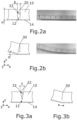
- eine Seitenansicht zweier Körperelemente gemäß der
Fig. 1 mit Photographie des entsprechenden Bauteils, - Fig. 2b:
- eine Seitenansicht gemäß der
Fig. 2a in einem gekrümmten Zustand, - Fig. 3a:
- eine Seitenansicht zweier Körperelemente gemäß der
Fig. 2a , wobei die Körperelemente einen trapezoidalen Querschnitt aufweisen, - Fig. 3b:
- eine Seitenansicht gemäß der
Fig. 3a in einem gekrümmten Zustand, - Fig. 4a bis Fig. 4c:
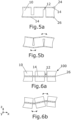
- eine Seitenansicht zweier Körperelemente gemäß der
Fig. 2a , wobei das konturierte Strukturelement in drei gebogenen Zuständen zwischen 0° und 180° dargestellt ist, - Fig. 5a:
- eine Seitenansicht des konturierten Strukturelements, wobei die Verbindungsschicht in der Grundfläche und der entgegengesetzten Oberfläche der Körperelemente angeordnet ist,
- Fig. 5b:
- eine Seitenansicht des konturierten Strukturelements gemäß der
Fig. 5a in einem zweifach gekrümmten Zustand, - Fig. 6a:
- eine Seitenansicht zweier konturierter Strukturelemente, die miteinander thermisch verschweißt sind und
- Fig. 6b:
- eine Seitenansicht zweier konturierter Strukturelemente gemäß der
Fig. 6a in einem zweifach gekrümmten Zustand, die miteinander thermisch verschweißt sind.
- Fig.1:
- a perspective view of the contoured structural element consisting of rectangular body elements with a connecting layer and a thermally compacted base surface,
- Fig. 2a:
- a side view of two body elements according to the
Fig.1 with photograph of the corresponding component, - Fig. 2b:
- a side view according to the
Fig. 2a in a curved state, - Fig. 3a:
- a side view of two body elements according to the
Fig. 2a , wherein the body elements have a trapezoidal cross-section, - Fig. 3b:
- a side view according to the
Fig. 3a in a curved state, - Fig. 4a to Fig. 4c:
- a side view of two body elements according to the
Fig. 2a , where the contoured structural element is shown in three bent states between 0° and 180°, - Fig. 5a:
- a side view of the contoured structural element, wherein the connecting layer is arranged in the base surface and the opposite surface of the body elements,
- Fig. 5b:
- a side view of the contoured structural element according to the
Fig. 5a in a double-curved state, - Fig. 6a:
- a side view of two contoured structural elements that are thermally welded together and
- Fig. 6b:
- a side view of two contoured structural elements according to the
Fig. 6a in a double-curved state, which are thermally welded together.
Gleiche Elemente beziehungsweise Elemente mit gleicher Funktion sind in den Figuren mit den gleichen Bezugsziffern versehen.Identical elements or elements with the same function are provided with the same reference numbers in the figures.
In der
Eine Oberflächenschicht 16 der Verbindungsschicht 12 und die daran angrenzende Oberflächenschicht 18 der Körperelemente 10 weisen eine thermisch verdichtete Schicht 14 auf. Die thermisch verdichtete Schicht 14 besteht aus dem gleichen Material wie die Körperelemente 10 und die Verbindungsschicht 12.A
Das konturierte Strukturelement 100 ist bevorzugt so unterteilt, dass die Oberflächenschicht 16 der Verbindungsschicht 12 und die Oberflächenschicht 18 der Körperelemente 10 die Grundfläche 26 des konturierten Strukturelements 100 ausbilden. Bevorzugt weist in diesem Fall die gesamte Grundfläche 26 des konturierten Strukturelements 100 eine vollflächig thermisch verdichtete Schicht 14 auf. Vorteilhafterweise ist diese vollflächig thermisch verdichtete Schicht 14 mittels eines Heißdrahtschneideverfahrens herstellbar, wobei in kurzer Zeit die gesamte Grundfläche 26 des konturierten Strukturelements 100 verdichtbar ist.The contoured
Vorzugsweise weist auch eine im planen Zustand des konturierten Strukturelements 100 parallel zur Grundfläche 26 ausgerichtete, den Verbindungsschicht 12 gegenüberliegende Oberfläche 24 der Körperelemente 10 eine thermisch verdichtete, bevorzugt teilversiegelte Oberflächenschicht 14 auf (siehe
Es sei angemerkt, dass die thermisch verdichtete Schicht 14 des konturierten Strukturelements 100 sich auf eine thermische Behandlung des konturierten Strukturelements 100 selbst bezieht und nicht auf eine nachträglich angebrachte/angeklebte thermisch verdichtete Schicht aus einem identischen oder anderem Material. Dies bedeutet, dass zwar ein Übergang von einem verdichteten zu einem nicht verdichteten Bereich im gleichen zusammenhängenden oder einstückigen Material gegeben ist, dass jedoch keine Verbindungsfläche oder Verbindungsflächen vorliegen, an denen unterschiedliche Materialschichten miteinander verbunden sind. Die Körperelemente 10, die Verbindungsschicht 12 und die thermisch verdichtete Schicht 14 sind also bevorzugt aus dem gleichen Material, sowie aus einem einstückigen Grundelement, zum Beispiel ein plattenförmiges Strukturelement, herstellbar.It should be noted that the thermally compacted
Alternativ ist es möglich, dass die Oberflächenschicht 16 der Verbindungsschicht 12 und die daran angrenzende Oberflächenschicht 18 der Körperelemente 10 teilweise, bevorzugt in einem Verbindungsbereich A, eine thermisch verdichtete Schicht 14 aufweisen, sodass insbesondere auch der Bereich der Kanten 28 zwischen der Verbindungsschicht 12 und den Körperelementen 10 durch die thermisch verdichtete Schicht 14 stabilisiert ist. Bei einer Biegebeanspruchung des konturierten Strukturelements 100 kann insbesondere der Bereich der Kanten 28 der Verbindungsschicht 12 aufgrund von erhöhten Kerbspannungen brechen, sodass die Oberflächenschicht 18 der Körperelemente 10 zumindest in dem Verbindungsbereich A verstärkt ist.Alternatively, it is possible for the
In einem planen Zustand des konturierten Strukturelements 100 bildet die thermisch verdichtete Schicht 14 bevorzugt eine plane und/oder gleichmäßig starke Schicht aus, sodass die Verbindungsschicht 12 gleichmäßig über die Grundfläche 26 des konturierten Strukturelements 100 verstärkt ist.In a planar state of the contoured
Weiter bevorzugt sind zumindest die für den Kontakt mit Harzmaterial vorgesehenen Oberflächen des konturierten Strukturelements 100 thermisch teilversiegelt. Zu den bevorzugten Oberflächen des konturierten Strukturelements 100 zählen insbesondere die Grundfläche 26 des konturierten Strukturelements 100 und die der Grundfläche 26 gegenüberliegende Oberfläche 24 der Körperelemente 10. Zusätzlich können auch die gemäß der
Vorzugsweise liegt die Dicke d der thermisch verdichteten Schicht 14 im planen Zustand des konturierten Strukturelements 100 senkrecht zur Grundfläche 26 zwischen 0.01mm und 1.00mm, bevorzugt zwischen 0.10mm und 0.70mm, besonders bevorzugt zwischen 0.15mm und 0.60mm, ganz besonders bevorzugt zwischen 0.25mm und 0.35mm. Bevorzugt bei dieser Dicke d der thermisch verdichteten Schicht 14 ist eine ausreichende mechanische Stabilität der Verbindungsschicht 12 und eine ausreichende Adhäsion zu einer Deckschicht eines Sandwich-Verbundelements gewährleistet. Dabei nimmt die mechanische Stabilität mit zunehmender Dicke d zu. Demgegenüber nimmt die Adhäsion zu einer Deckschicht mit zunehmender Dicke d ab, da Poren des thermoplastischen Kunststoffschaums zunehmend versiegelt werden, sodass in einem späteren Klebeprozess oder Laminierprozess oder Vakuuminjektionsprozess ein Harzmaterial sich nicht in der vergrößerten Oberfläche der Poren verankern kann.Preferably, the thickness d of the thermally compacted
Die Verbindungsschicht 12 kann so ausgeführt sein, dass sie gerade durch die thermisch verdichtete Schicht 14 selbst ausgebildet ist. Zum Beispiel kann das konturierte Strukturelement 100 bis in oder kurz vor die thermisch verdichtete Schicht 14 gesägt sein. So kann verhindert werden, dass nicht verdichtetes und deshalb sprödes Schaumstoffmaterial zwischen den Körperelementen 10 verbleibt, das unter Umständen leicht brechen kann und das Sandwich-Verbundelement verunreinigen kann oder durch lose Elemente die mechanische Stabilität des Sandwich-Verbundelements herabsetzen kann.The connecting
Alternativ sollte die thermisch nicht ausgehärtete Schicht der Verbindungsschicht 12 bevorzugt auf ein Minimum reduziert werden, da sie sonst die Krümmung des Strukturelements und die scharnierartige Wirkung der Verbindungsschicht 12 einschränken würde.Alternatively, the thermally uncured layer of the
Für die thermisch verdichtete, bevorzugt teilversiegelte Schicht 14 sollte ein Glanzwert der thermisch verdichteten Oberfläche, zum Beispiel die thermisch verdichtete Grundfläche 26, gemessen bei 60° nach DIN 67530-1982 zwischen 2 und 10 Glanzeinheiten betragen.For the thermally compacted, preferably partially sealed
Das konturierte Strukturelement 100 ist, wie in der
Wie in der
Der maximale Krümmungswinkel α zwischen zwei Körperelementen 10 liegt vorteilhafterweise zwischen 2° bis 3°, sodass die Steigungssprünge in der gekrümmte Oberfläche 26 des konturierten Strukturelements 100 klein genug sind, damit die Abweichung z.B. von einem Kreisbogen mit Harzmaterial ausgeglichen werden kann, sodass die Steigungssprünge in einer mit dem gekrümmten konturierten Strukturelement 100 verklebten Deckschicht nicht übertragen werden. Bei stark gekrümmten Sandwich-Verbundelementen muss entsprechend die Anzahl der Körperelemente 10 pro Längeneinheit erhöht werden.The maximum angle of curvature α between two
Um den Einschluss von Harzmaterial in dem Zwischenraum 32 zu verhindern, weisen die Körperelemente 10 alternativ einen trapezoidalen Querschnitt gemäß der
Vorzugsweise ist eine Breite b des Zwischenraums 32 zwischen den Körperelementen 10 und eine Höhe h des konturierten Strukturelements 100 oder eine Höhe des Zwischenraums 32 entsprechend der Krümmung des konturierten Strukturelements 100 so gewählt, dass im gekrümmten Zustand des konturierten Strukturelements 100 die sich einem Zwischenraum 32 zugewandten Oberflächen 20 der Körperelemente 10 zumindest teilweise, bevorzugt über die gesamte Oberfläche 20 kontaktieren. Mit einem geschlossenen Zwischenraum 32 kann eine Harzaufnahme verhindert werden. Dabei kann die Unterteilung des konturierten Strukturelements 100 von einem regelmäßigen schachbrettartigen Muster abweichen.Preferably, a width b of the
Weiterhin wäre es denkbar, Körperelemente 10 entlang der Kontaktfläche 30 miteinander thermisch zu verschweißen, sodass der gekrümmte Zustand des konturierten Strukturelements 100 gefestigt wird und um ein Vordringen von Harzmaterial in die Zwischenräume 32 der Körperelemente 10 dauerhaft zu verhindern. Bevorzugt sind die Kontaktflächen 30, wie in der
In der Handhabung des konturierten Strukturelements 100 oder für Sandwich-Verbundelemente mit Krümmungen in unterschiedliche Richtungen kann es vorkommen, dass das konturierte Strukturelement 100 so gebogen wird, dass der Zwischenraum 32 sich im Vergleich zu dem planen Zustand des konturierten Strukturelements 100 vergrößert. In der
Die hohe Dauerfestigkeit der thermisch verdichteten Schicht 14 ermöglicht den Ersatz eines Scrimmaterials, wobei die Stabilität nicht nur für eine geringe Krümmung in einer Form ausreichend gewährleistet ist, sondern auch für Beanspruchungen in der Handhabung des konturierten Strukturelements 100; zum Beispiel, wenn das konturierte Strukturelement 100 zugeschnitten oder in einer Form ausgerichtet werden soll.The high fatigue strength of the thermally compacted
Für ein konturiertes Strukturelement 100 mit beidseitig thermisch verdichteten Schichten 14 ist es gemäß der
Alternativ können auch zwei konturierte Strukturelemente 100 gemäß der
Vorzugsweise wird die verdichtete, bevorzugt teilversiegelte Schicht 14 durch Heißdrahtschneiden erzeugt. Mit dem Heißdrahtschneideverfahren kann das konturierte Strukturelement 100 aus einem Schaumstoffblock zugeschnitten und gleichzeitig kann die Grundfläche 26 des Strukturelements 100, sowie die der Grundfläche 26 gegenüberliegende Oberfläche 24 der Körperelemente 10 verdichtet und teilversiegelt werden.Preferably, the compacted, preferably partially sealed
Das in der
Ein Sandwich-Verbundelement kann hergestellt werden, indem auf die Grundfläche 26 des konturierten Strukturelements 100 und die der Grundfläche 26 gegenüberliegende Fläche 24 der Körperelemente 10 eine Deckschicht, insbesondere aus glasfaserverstärktem Kunststoff, vorzugsweise mittels eines Harzes festgelegt wird.A sandwich composite element can be produced by attaching a cover layer, in particular made of glass fiber reinforced plastic, preferably by means of a resin, to the
Vorzugsweise ist eine erste Deckschicht und/oder eine zweite Deckschicht im Infusionsverfahren festgelegt.Preferably, a first cover layer and/or a second cover layer is determined by the infusion process.
Das soweit beschriebene konturierte Strukturelement 100 kann in vielfältiger Art und Weise abgewandelt oder modifiziert werden, ohne vom Erfindungsgedanken abzuweichen. So ist es zum Beispiel denkbar, mit einem Heißdraht, Laser oder Heißelementstift die Zwischenräume 32 der Körperelemente 10 thermisch zu verdichten. So kann zum Beispiel das in
- 1010
- KörperelementBody element
- 1212
- VerbindungsschichtConnection layer
- 1414
- thermisch verdichtete Schichtthermally compacted layer
- 1616
- Oberfläche der VerbindungsschichtSurface of the bonding layer
- 1818
- Oberfläche des KörperelementsSurface of the body element
- 2020
- Oberfläche des Körperelements in einem ZwischenraumSurface of the body element in a gap
- 2424
- Der Grundfläche gegenüberliegende OberflächeSurface opposite the base
- 2626
- Grundfläche des konturierten StrukturelementsBase area of the contoured structural element
- 3030
- Kontaktfläche der KörperelementeContact surface of body elements
- 3232
- Zwischenraum zwischen den KörperelementenSpace between the body elements
- 100100
- Konturiertes StrukturelementContoured structural element
- x,y,zx,y,z
- Raumachsen eines kartesischen KoordinatensystemsSpatial axes of a Cartesian coordinate system
- αα
- KrümmungswinkelCurvature angle
- ββ
- Öffnungswinkel zwischen KörperelementenOpening angle between body elements
- γγ
- Öffnungswinkel zwischen trapezoidalen KörperelementenOpening angle between trapezoidal body elements
- hH
- Höhe des konturierten StrukturelementsHeight of the contoured structural element
- bb
- Breite des ZwischenraumsWidth of the gap
- dd
- Dicke der thermisch verdichteten SchichtThickness of the thermally compacted layer
Claims (13)
- A contoured structural element (100) for being used as a core layer in a bent sandwich composite element, the contoured structural element (100) being made of a thermoplastic plastic foam, in particular PET, the contoured structural element (100) being divided down to a joining layer (12) into several body elements (10) and the body elements (10) and the joining layer (12) being oriented parallel to a base (26) of the contoured structural element (100) which is in a plane state, at least a surface layer (16) of the joining layer (12) and the surface layer (18) of the body elements (10) which is adjacent thereto having at least partially a thermally compacted layer (14) and the body elements (10), the joining layer (12) and the thermally compacted layer (14) being made of the same material,
characterized in that
at least a surface layer (16) of the joining layer (12) and the surface layer (18) of the body elements (10) which is adjacent thereto realize the base (26) of the contoured structural element (100) and in that the thermally compacted layer (14), preferably a partially sealed layer, extends across the entire surface of the base (26) of the contoured structural element (100). - The contoured structural element according to claim 1,
characterized in that
a surface of the body elements (24) which is opposite the joining layer (12) and which is oriented parallel to the base (26) in the plane state of the structural elements (100) also has a thermally compacted surface layer (14), which is preferably partially sealed. - The contoured structural element according to claim 1 or 2,
characterized in that
the thermally compacted layer (14) realizes a plane and/or evenly strong layer in a plane state of the structural element (100). - The contoured structural element according to any one of claims 1 to 3,
characterized in that
at least the surfaces of the structural element (100) which are intended for contact with resin material are thermally partially sealed. - The contoured structural element according to any one of claims 1 to 4,
characterized in that
the thickness (d) of the thermally compacted layer (14) perpendicular to the base is between 0,01 mm and 1,00 mm, preferably between 0,10 mm and 0,70 mm, especially preferably between 0,15 mm and 0,60 mm, most preferably between 0,25 mm and 0,35 mm, in the plane state of the structural element (100). - The contoured structural element according to any one of claims 1 to 5,
characterized in that
the thermally compacted layer (14) realizes the joining layer (12). - The contoured structural element according to any one of claims 1 to 6,
characterized in that
a gloss value of a surface of the thermally compacted layer (14) measured at 60° according to DIN 67530-1982 is between 2 and 10 gloss units. - The contoured structural element according to any one of claims 1 to 7,
characterized in that
the structural element (100) is divided into body elements (10) according to a regular checkered and/or hexagonal pattern and/or the body elements (10) have a rectangular cross section (20) or a trapezoidal cross section (22). - The contoured structural element according to any one of claims 1 to 8,
characterized in that
the body elements (10) are thermally welded to each other, preferably their surfaces, in the bent state of the structural element (100). - The contoured structural element according to any one of claims 1 to 9,
characterized in that
the compacted layer (14), which is preferably partially sealed, is generated by hot-wire cutting. - A method for fabricating a contoured structural element according to any one of the preceding claims 1 to 10, said method comprising the steps of:- providing a preferably panel-shaped structural element made of an extrusion-foamed thermoplastic resin,- producing, in particular cutting, recesses in at least one side, in particular the side opposite the base 26 of the panel-shaped structural element, by means of sawing, laser engraving, milling or hot cutting methods such that the panel-shaped structural element is divided down to a joining layer (12) into several body elements (10),characterized by
producing a thermally compacted layer (14) in at least a surface layer (16) of the joining layer (12) and at least partially in the surface layer (18) of the body elements (10) which is adjacent thereto, and in the base (26). - A method for the fabrication of a sandwich composite element bent on one side or on several sides comprising a contoured structural element according to any one of claims 1 to 10, said method comprising the steps of:- bending the contoured structural element (100) on one side or on several sides,- bonding at least of one side of the contoured structural element (100) to a face sheet made of adhesive resin, in particular a fiber-reinforced plastic, preferably in an infusion method.
- A sandwich composite element bent on one side or on several sides, in particular for the fabrication of a wind turbine blade for wind turbines and/or for applications in the marine sector and/or in the rail transport sector and/or in mass transportation on the road and/or for structural applications in the construction sector, said sandwich composite element bent on one side or on several sides comprising a contoured structural element according to any one of claims 1 to 10 as a core layer, wherein a face sheet, which is in particular made of or comprises fiber-reinforced plastic, is fixed by means of an adhesive resin on at least one side of the contoured structural element.
Priority Applications (8)
| Application Number | Priority Date | Filing Date | Title |
|---|---|---|---|
| EP20188418.6A EP3944944B1 (en) | 2020-07-29 | 2020-07-29 | Contoured structural element and manufacture of the contoured structural element |
| PCT/EP2021/069707 WO2022023049A1 (en) | 2020-07-29 | 2021-07-15 | Contoured structural element and production of the contoured structural element |
| BR112022025607A BR112022025607A2 (en) | 2020-07-29 | 2021-07-15 | CONTOURED STRUCTURAL ELEMENT AND MANUFACTURE OF THE CONTOURED STRUCTURAL ELEMENT |
| MX2023000934A MX2023000934A (en) | 2020-07-29 | 2021-07-15 | Contoured structural element and production of the contoured structural element. |
| US18/018,313 US20230294377A1 (en) | 2020-07-29 | 2021-07-15 | Contoured structural element and production of the contoured structural element |
| CA3186553A CA3186553A1 (en) | 2020-07-29 | 2021-07-15 | Contoured structural element and production of the contoured structural element |
| CN202180064408.3A CN116209556A (en) | 2020-07-29 | 2021-07-15 | Contour structural element and production of contour structural element |
| AU2021318709A AU2021318709A1 (en) | 2020-07-29 | 2021-07-15 | Contoured structural element and production of the contoured structural element |
Applications Claiming Priority (1)
| Application Number | Priority Date | Filing Date | Title |
|---|---|---|---|
| EP20188418.6A EP3944944B1 (en) | 2020-07-29 | 2020-07-29 | Contoured structural element and manufacture of the contoured structural element |
Publications (2)
| Publication Number | Publication Date |
|---|---|
| EP3944944A1 EP3944944A1 (en) | 2022-02-02 |
| EP3944944B1 true EP3944944B1 (en) | 2024-04-24 |
Family
ID=71846304
Family Applications (1)
| Application Number | Title | Priority Date | Filing Date |
|---|---|---|---|
| EP20188418.6A Active EP3944944B1 (en) | 2020-07-29 | 2020-07-29 | Contoured structural element and manufacture of the contoured structural element |
Country Status (8)
| Country | Link |
|---|---|
| US (1) | US20230294377A1 (en) |
| EP (1) | EP3944944B1 (en) |
| CN (1) | CN116209556A (en) |
| AU (1) | AU2021318709A1 (en) |
| BR (1) | BR112022025607A2 (en) |
| CA (1) | CA3186553A1 (en) |
| MX (1) | MX2023000934A (en) |
| WO (1) | WO2022023049A1 (en) |
Families Citing this family (1)
| Publication number | Priority date | Publication date | Assignee | Title |
|---|---|---|---|---|
| CN116277316A (en) * | 2023-04-04 | 2023-06-23 | 青岛钰坤睿新材料科技有限公司 | Arc-shaped plate structure, arc-shaped composite plate and processing method of arc-shaped composite plate |
Citations (1)
| Publication number | Priority date | Publication date | Assignee | Title |
|---|---|---|---|---|
| DE10034990B4 (en) * | 2000-07-19 | 2005-02-10 | Airbus Deutschland Gmbh | Multi-layer panel for reducing the sound radiation |
Family Cites Families (9)
| Publication number | Priority date | Publication date | Assignee | Title |
|---|---|---|---|---|
| US3540967A (en) | 1968-01-12 | 1970-11-17 | Balsa Dev Corp | Machine for making contour-core structures |
| US3841958A (en) * | 1971-09-02 | 1974-10-15 | R Delorme | Reinforced structural element and method of making the same |
| NL156084B (en) * | 1972-04-18 | 1978-03-15 | Chemacryl Plastics Ltd | FLEXIBLE PLATE OF A RIGID, ELASTIC FOAM PLASTIC, INTENDED FOR CORE LAYER IN A CURVED, LAYERED STRUCTURE. |
| US4121008A (en) * | 1975-02-07 | 1978-10-17 | Unitex Limited | Foam sandwich constructions |
| EP2160287B1 (en) * | 2007-06-29 | 2012-11-28 | Lm Glasfiber A/S | A method for producing a composite structure and a composite structure |
| WO2011040970A1 (en) | 2009-10-01 | 2011-04-07 | Webcore Ip, Inc. | Composite cores and panels |
| DE102012102689A1 (en) | 2012-03-26 | 2013-09-26 | Airex Ag | Structural element and method for its production |
| DE102015203375A1 (en) * | 2015-02-25 | 2016-08-25 | Hochschule Für Angewandte Wissenschaften - Fachhochschule Kempten | Process for processing a foam workpiece |
| AT521722A1 (en) * | 2018-09-24 | 2020-04-15 | Troi Valentine | Structural element for free-form surfaces |
-
2020
- 2020-07-29 EP EP20188418.6A patent/EP3944944B1/en active Active
-
2021
- 2021-07-15 MX MX2023000934A patent/MX2023000934A/en unknown
- 2021-07-15 CN CN202180064408.3A patent/CN116209556A/en active Pending
- 2021-07-15 US US18/018,313 patent/US20230294377A1/en active Pending
- 2021-07-15 CA CA3186553A patent/CA3186553A1/en active Pending
- 2021-07-15 BR BR112022025607A patent/BR112022025607A2/en unknown
- 2021-07-15 WO PCT/EP2021/069707 patent/WO2022023049A1/en active Application Filing
- 2021-07-15 AU AU2021318709A patent/AU2021318709A1/en active Pending
Patent Citations (1)
| Publication number | Priority date | Publication date | Assignee | Title |
|---|---|---|---|---|
| DE10034990B4 (en) * | 2000-07-19 | 2005-02-10 | Airbus Deutschland Gmbh | Multi-layer panel for reducing the sound radiation |
Also Published As
| Publication number | Publication date |
|---|---|
| WO2022023049A1 (en) | 2022-02-03 |
| EP3944944A1 (en) | 2022-02-02 |
| AU2021318709A1 (en) | 2023-02-16 |
| BR112022025607A2 (en) | 2023-02-23 |
| MX2023000934A (en) | 2023-03-10 |
| US20230294377A1 (en) | 2023-09-21 |
| CN116209556A (en) | 2023-06-02 |
| CA3186553A1 (en) | 2022-02-03 |
Similar Documents
| Publication | Publication Date | Title |
|---|---|---|
| EP3237702B1 (en) | Honeycomb structure | |
| AT510694B1 (en) | MODULE FOR HOLDING AT LEAST ONE POD | |
| EP2288487B1 (en) | Method for the production of a rotor blade for a wind turbine | |
| DE602005002300T2 (en) | A method of making a structural composite beam for aircraft | |
| EP1798428B1 (en) | Braided composite part | |
| DE19956394B4 (en) | Process for producing a profile from a hybrid material | |
| EP2670591B2 (en) | Structural element and method for the production thereof | |
| EP2481569A1 (en) | Motor vehicle component and method for manufacturing same | |
| EP3496936A1 (en) | Spar cap made of prefabricated elements with laid fabric and method for producing same | |
| EP3606742B1 (en) | Method of forming a flat composite component and composite component produced in this way | |
| EP2681095B1 (en) | Component for rail vehicles | |
| DE102005030939A1 (en) | Method for producing a substantially cup-shaped component | |
| DE102008057708B4 (en) | Composite fiber preform, fiber composite workpiece, and method of making a fiber composite workpiece | |
| EP3944944B1 (en) | Contoured structural element and manufacture of the contoured structural element | |
| DE102006023865A1 (en) | Production of fiber-reinforced component, e.g. thick laminate, by partially hardening stack of impregnated fibrous layers, stacking again, compacting and combining with further stack | |
| EP0394639B1 (en) | Gripper rod made from fibre-reinforced synthetic bands | |
| DE102009010621B3 (en) | Method for stabilization of honeycomb core for sandwich composite structures made of fiber-reinforced composites, involves pre-fixing honeycomb core at open-cell side on manufacturing equipment with textured surface | |
| DE4133416A1 (en) | Procedure for production of insulation board - Involves compounding of several layers of fibre where each layer is arranged or manufactured differently for increasing weight to strength ratio of board | |
| DE202012007340U1 (en) | Core element and core layer for a sandwich composite component, sandwich composite component | |
| EP3504046B1 (en) | Fiber reinforced foam | |
| WO2019034211A1 (en) | Plastic fiber composite material/aluminum laminate, production and use thereof | |
| EP2295216B1 (en) | Method for producing a honeycomb structure from a semi-finished fibre product | |
| EP3487703A1 (en) | Surfboard and method for producing same | |
| DE102017111126B4 (en) | Sandwich plate for rail vehicles and method for their production | |
| AT517696B1 (en) | Fiber reinforced plastic body |
Legal Events
| Date | Code | Title | Description |
|---|---|---|---|
| PUAI | Public reference made under article 153(3) epc to a published international application that has entered the european phase |
Free format text: ORIGINAL CODE: 0009012 |
|
| STAA | Information on the status of an ep patent application or granted ep patent |
Free format text: STATUS: THE APPLICATION HAS BEEN PUBLISHED |
|
| AK | Designated contracting states |
Kind code of ref document: A1 Designated state(s): AL AT BE BG CH CY CZ DE DK EE ES FI FR GB GR HR HU IE IS IT LI LT LU LV MC MK MT NL NO PL PT RO RS SE SI SK SM TR |
|
| STAA | Information on the status of an ep patent application or granted ep patent |
Free format text: STATUS: REQUEST FOR EXAMINATION WAS MADE |
|
| 17P | Request for examination filed |
Effective date: 20220509 |
|
| RBV | Designated contracting states (corrected) |
Designated state(s): AL AT BE BG CH CY CZ DE DK EE ES FI FR GB GR HR HU IE IS IT LI LT LU LV MC MK MT NL NO PL PT RO RS SE SI SK SM TR |
|
| GRAP | Despatch of communication of intention to grant a patent |
Free format text: ORIGINAL CODE: EPIDOSNIGR1 |
|
| STAA | Information on the status of an ep patent application or granted ep patent |
Free format text: STATUS: GRANT OF PATENT IS INTENDED |
|
| INTG | Intention to grant announced |
Effective date: 20231130 |
|
| RIN1 | Information on inventor provided before grant (corrected) |
Inventor name: RAKUTT, DIETMAR Inventor name: GAUL, MARTIN Inventor name: GAETZI, ROMAN |
|
| GRAS | Grant fee paid |
Free format text: ORIGINAL CODE: EPIDOSNIGR3 |
|
| GRAA | (expected) grant |
Free format text: ORIGINAL CODE: 0009210 |
|
| STAA | Information on the status of an ep patent application or granted ep patent |
Free format text: STATUS: THE PATENT HAS BEEN GRANTED |
|
| AK | Designated contracting states |
Kind code of ref document: B1 Designated state(s): AL AT BE BG CH CY CZ DE DK EE ES FI FR GB GR HR HU IE IS IT LI LT LU LV MC MK MT NL NO PL PT RO RS SE SI SK SM TR |
|
| REG | Reference to a national code |
Ref country code: GB Ref legal event code: FG4D Free format text: NOT ENGLISH |
|
| REG | Reference to a national code |
Ref country code: CH Ref legal event code: EP |
|
| REG | Reference to a national code |
Ref country code: DE Ref legal event code: R096 Ref document number: 502020007736 Country of ref document: DE |