EP3944550B1 - Signaling of multiple short tti transmissions - Google Patents
Signaling of multiple short tti transmissions Download PDFInfo
- Publication number
- EP3944550B1 EP3944550B1 EP21195959.8A EP21195959A EP3944550B1 EP 3944550 B1 EP3944550 B1 EP 3944550B1 EP 21195959 A EP21195959 A EP 21195959A EP 3944550 B1 EP3944550 B1 EP 3944550B1
- Authority
- EP
- European Patent Office
- Prior art keywords
- stti
- downlink
- sttis
- scheduled
- uplink
- Prior art date
- Legal status (The legal status is an assumption and is not a legal conclusion. Google has not performed a legal analysis and makes no representation as to the accuracy of the status listed.)
- Active
Links
- 230000005540 biological transmission Effects 0.000 title claims description 105
- 230000011664 signaling Effects 0.000 title description 20
- 238000000034 method Methods 0.000 claims description 34
- 238000004891 communication Methods 0.000 claims description 10
- 238000004590 computer program Methods 0.000 claims description 5
- 238000012545 processing Methods 0.000 description 20
- 238000013468 resource allocation Methods 0.000 description 12
- 230000008569 process Effects 0.000 description 11
- 125000004122 cyclic group Chemical group 0.000 description 7
- 230000006870 function Effects 0.000 description 7
- 238000010586 diagram Methods 0.000 description 5
- 230000009467 reduction Effects 0.000 description 5
- 230000010267 cellular communication Effects 0.000 description 4
- 238000000794 confocal Raman spectroscopy Methods 0.000 description 4
- 238000011500 cytoreductive surgery Methods 0.000 description 4
- 238000005516 engineering process Methods 0.000 description 4
- 230000007774 longterm Effects 0.000 description 3
- 238000013459 approach Methods 0.000 description 2
- 230000008859 change Effects 0.000 description 2
- 238000013461 design Methods 0.000 description 2
- 208000008487 fibromuscular dysplasia Diseases 0.000 description 2
- 238000007726 management method Methods 0.000 description 2
- 238000013507 mapping Methods 0.000 description 2
- 239000011159 matrix material Substances 0.000 description 2
- 230000007246 mechanism Effects 0.000 description 2
- 238000012986 modification Methods 0.000 description 2
- 230000004048 modification Effects 0.000 description 2
- 230000003287 optical effect Effects 0.000 description 2
- 238000012546 transfer Methods 0.000 description 2
- 206010009944 Colon cancer Diseases 0.000 description 1
- 230000002776 aggregation Effects 0.000 description 1
- 238000004220 aggregation Methods 0.000 description 1
- 238000003491 array Methods 0.000 description 1
- 230000001419 dependent effect Effects 0.000 description 1
- 238000003780 insertion Methods 0.000 description 1
- 230000037431 insertion Effects 0.000 description 1
- 238000005259 measurement Methods 0.000 description 1
- 230000004043 responsiveness Effects 0.000 description 1
- 230000003595 spectral effect Effects 0.000 description 1
- 238000001228 spectrum Methods 0.000 description 1
- 238000012360 testing method Methods 0.000 description 1
- 208000037918 transfusion-transmitted disease Diseases 0.000 description 1
Images


Classifications
-
- H—ELECTRICITY
- H04—ELECTRIC COMMUNICATION TECHNIQUE
- H04W—WIRELESS COMMUNICATION NETWORKS
- H04W72/00—Local resource management
- H04W72/20—Control channels or signalling for resource management
- H04W72/23—Control channels or signalling for resource management in the downlink direction of a wireless link, i.e. towards a terminal
-
- H—ELECTRICITY
- H04—ELECTRIC COMMUNICATION TECHNIQUE
- H04L—TRANSMISSION OF DIGITAL INFORMATION, e.g. TELEGRAPHIC COMMUNICATION
- H04L5/00—Arrangements affording multiple use of the transmission path
- H04L5/003—Arrangements for allocating sub-channels of the transmission path
- H04L5/0078—Timing of allocation
- H04L5/0082—Timing of allocation at predetermined intervals
-
- H—ELECTRICITY
- H04—ELECTRIC COMMUNICATION TECHNIQUE
- H04L—TRANSMISSION OF DIGITAL INFORMATION, e.g. TELEGRAPHIC COMMUNICATION
- H04L5/00—Arrangements affording multiple use of the transmission path
- H04L5/0091—Signaling for the administration of the divided path
- H04L5/0094—Indication of how sub-channels of the path are allocated
-
- H—ELECTRICITY
- H04—ELECTRIC COMMUNICATION TECHNIQUE
- H04L—TRANSMISSION OF DIGITAL INFORMATION, e.g. TELEGRAPHIC COMMUNICATION
- H04L5/00—Arrangements affording multiple use of the transmission path
- H04L5/003—Arrangements for allocating sub-channels of the transmission path
- H04L5/0048—Allocation of pilot signals, i.e. of signals known to the receiver
- H04L5/0051—Allocation of pilot signals, i.e. of signals known to the receiver of dedicated pilots, i.e. pilots destined for a single user or terminal
-
- H—ELECTRICITY
- H04—ELECTRIC COMMUNICATION TECHNIQUE
- H04L—TRANSMISSION OF DIGITAL INFORMATION, e.g. TELEGRAPHIC COMMUNICATION
- H04L5/00—Arrangements affording multiple use of the transmission path
- H04L5/003—Arrangements for allocating sub-channels of the transmission path
- H04L5/0053—Allocation of signaling, i.e. of overhead other than pilot signals
-
- H—ELECTRICITY
- H04—ELECTRIC COMMUNICATION TECHNIQUE
- H04L—TRANSMISSION OF DIGITAL INFORMATION, e.g. TELEGRAPHIC COMMUNICATION
- H04L5/00—Arrangements affording multiple use of the transmission path
- H04L5/0001—Arrangements for dividing the transmission path
- H04L5/0003—Two-dimensional division
- H04L5/0005—Time-frequency
- H04L5/0007—Time-frequency the frequencies being orthogonal, e.g. OFDM(A), DMT
-
- H—ELECTRICITY
- H04—ELECTRIC COMMUNICATION TECHNIQUE
- H04W—WIRELESS COMMUNICATION NETWORKS
- H04W72/00—Local resource management
- H04W72/04—Wireless resource allocation
- H04W72/044—Wireless resource allocation based on the type of the allocated resource
- H04W72/0446—Resources in time domain, e.g. slots or frames
Definitions
- the present disclosure relates to scheduling short transmission time interval transmissions in a wireless communications network.
- LTE Long Term Evolution
- TTI Transmission Time Interval
- LTE uses Orthogonal Frequency Division Multiplexing (OFDM) in the downlink and Single Carrier OFDM (SC-OFDM) in the uplink.
- OFDM Orthogonal Frequency Division Multiplexing
- SC-OFDM Single Carrier OFDM
- the basic LTE downlink physical resource can thus be seen as a time-frequency grid as illustrated in Figure 2 , where each resource element corresponds to one OFDM subcarrier during one OFDM symbol interval.
- RBs Resource Blocks
- a RB corresponds to one slot (0.5 ms) in the time domain and 12 contiguous subcarriers in the frequency domain.
- RBs are numbered in the frequency domain, starting with 0 from one end of the system bandwidth.
- N RB UL is the number of RBs contained in the uplink system bandwidth
- N symb UL is the number of SC-OFDM symbols in each slot.
- N symb UL 7 for normal Cyclic Prefix (CP)
- N symb UL 6 for extended CP.
- a subcarrier and a SC-OFDM symbol form an uplink Resource Element (RE).
- RE uplink Resource Element
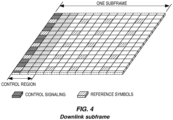
- Downlink data transmissions from an eNB to a UE are dynamically scheduled, i.e., in each subframe the base station transmits control information about to which terminals data is transmitted and upon which RBs the data is transmitted, in the current downlink subframe or the downlink part (DwPTS) of the current special subframe.
- This control signaling is typically transmitted in the first 1, 2, 3, or 4 OFDM symbols in each subframe.
- a downlink subframe with three OFDM symbols as control is illustrated in Figure 4 .
- uplink transmissions from a UE to an eNB are also dynamically scheduled through the downlink control channel.
- FDD Frequency Division Duplexing
- TDD Time Division Duplexing
- LTE Long Term Evolution
- LTE Long Term Evolution
- PDSCH is used mainly for carrying user traffic data and higher layer messages in the downlink and is transmitted in a downlink subframe outside of the control region as shown in Figure 4 .
- Both PDCCH and ePDCCH are used to carry Downlink Control Information (DCI) such as Physical RB (PRB) allocation, Modulation and Coding Scheme (MCS), precoder used at the transmitter, etc.
- DCI Downlink Control Information
- PRB Physical RB
- MCS Modulation and Coding Scheme
- PDCCH and ePDCCH are transmitted once per 1 ms subframe. Furthermore, a PDCCH is distributed over the whole carrier bandwidth, but is time multiplexed with PDSCH over the first 1-4 symbols in the subframe. An ePDCCH is distributed over the whole 1 ms subframe, but is frequency multiplexed with PDSCH and multiplexed onto one or multiple PRB pairs for localized and distributed transmission respectively.
- PDCCH has a common search space where all UEs need to detect common cell specific control information. Depending whether the UE has been configured for ePDCCH or not, it searches UE specific control information from UE search space of ePDCCH or PDCCH, respectively.
- the size of the PDCCH region can change dynamically on subframe basis. Recall that the size of the PDCCH region is signaled on the Physical Control Format Indicator Channel (PCFICH) in the beginning of the 1 ms subframe.
- PCFICH Physical Control Format Indicator Channel
- the frequency domain allocation of the ePDCCH is semi-statically configured by means of higher layer signaling.
- the PUSCH is used to carry uplink data or/and uplink control information from the UE to the eNB.
- the PUCCH is used to carry uplink control information from the UE to the eNB.
- the current control channels carry control information, referred to as DCI.
- DCI Downlink Control Channel
- the DCI format has a Cyclic Redundancy Check (CRC) which is scrambled by a UE identifier, such as a Cell Radio Network Temporary Identifier (C-RNTI), and when the CRCs match, after descrambling, a PDCCH with a certain DCI format has been detected.
- CRC Cyclic Redundancy Check
- SI-RNTI System Information Radio Network Temporary Identifier
- the DCI for a downlink scheduling assignment hence contains information on downlink data resource allocation in the frequency domain (the resource allocation), MCS, and HARQ process information.
- information related to which carrier the PDSCH is transmitted on may be included as well.
- DCI format 0 There are two main families of DCI formats for uplink grants, DCI format 0 and DCI format 4. The latter is added in Release 10 for supporting uplink spatial multiplexing.
- DCI format variants exist for both DCI format 0 and DCI format 4 for various purposes, e.g. scheduling in unlicensed spectrum.
- the DCI for an uplink scheduling grant contains:
- Packet data latency is one of the performance metrics that vendors, operators, and also end-users (via speed test applications) measure regularly. Latency measurements are done in all phases of a radio access network system lifetime, when verifying a new software release or system component, when deploying a system, and when the system is in commercial operation.
- LTE Long Term Evolution
- Packet data latency is important not only for the perceived responsiveness of the system; it is also a parameter that indirectly influences the throughput of the system.
- HTTP Hypertext Transfer Protocol
- TCP Transmission Control Protocol
- HTTP Archive http://httparchive.org/trends.php
- the typical size of HTTP based transactions over the Internet are in the range of a few tens of kilobytes up to one megabyte.
- the TCP slow start period is a significant part of the total transport period of the packet stream.
- TCP slow start the performance is latency limited. Hence, improved latency can rather easily be showed to improve the average throughput for this type of TCP based data transactions.
- Latency reductions could positively impact radio resource efficiency.
- Lower packet data latency could increase the number of transmissions possible within a certain delay bound; hence higher Block Error Rate (BLER) targets could be used for the data transmissions freeing up radio resources potentially improving the capacity of the system.
- BLER Block Error Rate
- a TTI corresponds to one subframe of length 1 ms.
- One such 1 ms TTI is constructed by using 14 OFDM or Single Carrier- Frequency Division Multiple Access (SC-FDMA) symbols in the case of normal CP and 12 OFDM or SC-FDMA symbols in the case of extended CP.
- SC-FDMA Single Carrier- Frequency Division Multiple Access
- a minimum required processing time is specified and applied for the downlink HARQ feedback timing and the uplink grant to uplink data delay.
- the latter is also called uplink scheduling timing.
- the minimum processing time will be reduced.
- the minimum required processing timing could be k-1 sTTI, resulting in a timing of n+k.
- a UE receiving a downlink assignment for a downlink sTTI received in downlink sTTI n is expected to transmit the downlink HARQ feedback in uplink sTTI n+k.
- the same can be applied for the uplink scheduling timing.
- a UE receiving an uplink grant for an uplink sTTI in downlink sTTI n is expected to transmit the uplink data in uplink sTTI n+k.
- the sTTI n+k may not be a valid uplink sTTI, in which case special rules for the timing can be defined but the minimum processing timing cannot be earlier than n+k.
- the timing n+k may not always correspond to a valid sTTI in uplink, in which case special rules can be defined, such as HARQ feedback or uplink data should be sent in the earliest uplink sTTI after n+k.
- An sTTI can be decided to have any duration in time and comprise resources on a number of OFDM or SC-FDMA symbols within a 1 ms subframe.
- the duration of the uplink sTTI is 0.5 ms, i.e. seven SC-FDMA symbols for the case with normal CP.
- the durations of the uplink sTTIs within a subframe are of 2 or 3 symbols.
- the "R” in the figures indicates the DMRS symbols
- S indicates the SRS symbols.
- DMRS overhead can be 50%, leading to a significant performance loss in terms of throughput and spectral efficiency.
- different DMRS design options have been considered to reduce the DMRS overhead:
- Example mechanisms depicted in Figure 7 and Figure 8 would work both for DMRS sharing and DMRS multiplexing.
- DMRS multiplexing consider the example of UE 1 scheduled in sTTI 0 and UE 2 in sTTI 1.
- UE 1 will transmit data in SC-FDMA symbols 0 and 1 and DMRS in symbol 2.
- UE 2 will transmit DMRS in the same symbol and data in symbols 3 and 4.
- UE 1 will transmit DMRS in symbol 0 and data in symbols 1 and 2.
- UE 2 will transmit DMRS in symbol 0, be silent in symbols 1 and 2, and send data in symbols 3 and 4.
- UE 1 In case of DMRS sharing, UE 1 is scheduled in both sTTI 0 and sTTI 1. In Figure 7 , UE 1 transmits data in symbols 0, 1, 3, and 4 and DMRS in symbol 2. In Figure 8 , UE 1 transmits data in symbols 1, 2, 3, and 4 and DMRS in symbol 0.
- Figure 9 shows examples for 2 or 3-symbol downlink sTTI configurations within a subframe.
- Downlink transmissions can be CRS based or DMRS based.
- the DMRS sharing option as explained for uplink, can also be used for downlink sTTI transmissions to reduce the DMRS overhead.
- short PDSCH sPDSCH
- short PUSCH sPUSCH
- sPDCCH downlink physical control channels
- sDCI short DCI
- the control channel carrying this sDCI can be either PDCCH or sPDCCH.
- WO 2017/018758 A1 discloses a method and an apparatus for transmitting/receiving downlink control information.
- Downlink control information about a data channel may be transmitted through one of a plurality of decoding candidates.
- the downlink control information is transmitted through one of the candidates for the first sub-frame or one of the candidates for the second sub-frame, from among the plurality of decoding candidates.
- the second sub-frame is shorter than the first sub-frame and can be set within the first sub-frame.
- Radio Node As used herein, a "radio node” is either a radio access node or a wireless device.
- Radio Access Node As used herein, a "radio access node” or “radio network node” is any node in a radio access network of a cellular communications network that operates to wirelessly transmit and/or receive signals.
- a radio access node include, but are not limited to, a base station (e.g., a New Radio (NR) base station (gNB) in a 3GPP Fifth Generation (5G) NR network or an eNB in a 3GPP LTE network), a high-power or macro base station, a low-power base station (e.g., a micro base station, a pico base station, a home eNB, or the like), and a relay node.
- NR New Radio
- a "core network node” is any type of node in a core network.
- Some examples of a core network node include, e.g., a Mobility Management Entity (MME), a Packet Data Network Gateway (P-GW), a Service Capability Exposure Function (SCEF), or the like.
- MME Mobility Management Entity
- P-GW Packet Data Network Gateway
- SCEF Service Capability Exposure Function
- a "wireless device” is any type of device that has access to (i.e., is served by) a cellular communications network by wirelessly transmitting and/or receiving signals to a radio access node(s).
- a wireless device include, but are not limited to, a UE in a 3GPP network and a Machine Type Communication (MTC) device.
- MTC Machine Type Communication
- Network Node As used herein, a "network node” is any node that is either part of the radio access network or the core network of a cellular communications network/system.
- sTTI Short Transmission Time Interval
- the nominal transmission duration is called a subframe and is composed of 14 OFDM/SC-FDMA symbols with normal cyclic prefix.
- a 2 or 3 OFDM symbol long transmission can also be referred to as subslot transmission, while a 7 OFDM symbol long transmission can also be referred to as slot transmission.
- the nominal transmission duration is called a slot and is composed of 14 OFDM/SC-FDMA symbols with normal cyclic prefix.
- PDSCH/PUSCH type B mini-slot/non-slot based transmission
- the eNB transmits corresponding control information using a new DCI format, referred to as short DCI (sDCI), in each downlink sTTI.
- the control channel carrying this sDCI can be either PDCCH or sPDCCH.
- transmitting sDCI in every single sTTI represents a high control overhead, especially for 2/3-symbol sTTI. This means that the number of available REs to be used for data transmission is reduced due to the RE utilized for the sDCI transmissions. This overhead can be seen as unnecessary when a UE is scheduled in consecutive sTTIs within a 1 ms subframe under similar channel conditions.
- a UE For DMRS sharing, a UE is scheduled with multiple consecutive sTTIs, and the DMRS is only transmitted in the first sTTI to reduce the overhead. If an sDCI is intended for scheduling only a single sTTI transmission, then multiple scheduling assignments/grants should be sent for scheduling these consecutive sTTls. This will increase the control signaling overhead.
- the UE misses the first uplink grant, so it will not transmit DMRS. Then, the eNB will not be able to decode the following sTTI transmissions due to lack of channel information.
- Embodiments of the present disclosure support the scheduling of multiple sTTI transmissions for both downlink and uplink transmissions - CRS based for downlink and DMRS based for downlink and uplink - to reduce both the DMRS overhead based on DMRS sharing and control signaling overhead from the sDCI transmissions.
- embodiments of the present disclosure provide the same reliability for DMRS sharing as for the single sTTI transmission for downlink and uplink.
- FIG. 10 illustrates one example of a wireless communication network 10 (e.g., an LTE (e.g., LTE Advanced (LTE-A), LTE-Pro, or an enhanced version of LTE) or 5G NR network) in which embodiments of the present disclosure may be implemented.
- LTE LTE Advanced
- LTE-Pro LTE-Pro
- 5G NR network 5G NR network
- a number of wireless devices 12 e.g., UEs
- wirelessly transmit signals to and receive signals from radio access nodes 14 e.g., eNBs or gNBs, which is a 5G NR base station
- the radio access nodes 14 are connected to a core network 18.
- FIG 11 illustrates the operation of the radio access node 14 and the wireless device 12 according to some embodiments of the present disclosure.
- this process is performed by the radio access node 14 (or more generally a network node) to provide scheduling of multiple sTTI transmissions in uplink and/or downlink.
- the radio access node 14 transmits a control information message to the wireless device 12 (step 100).
- the control information message is for one or more scheduled sTTI transmissions, which may be uplink transmissions or downlink transmissions.
- the control information message includes scheduling information that indicates the sTTI(s) for the scheduled sTTI transmission(s) and/or an indication of a timing for the scheduled sTTI transmission(s) and/or an indication of a DMRS configuration for the scheduled sTTI transmission(s). Further, as discussed below, in some embodiments, the control information message is for two or more scheduled sTTI transmissions, e.g., in two or more consecutive sTTIs in the time domain.
- the control information message includes scheduling information that indicates the sTTI(s) for the scheduled sTTI transmission(s), where the scheduling information is uplink scheduling information and/or downlink scheduling information.
- the scheduled sTTI transmission(s) are uplink transmission(s) or downlink transmission(s).
- the control information includes scheduling information that indicates two or more sTTIs for two or more sTTI transmissions, respectively, where the two or more sTTIs are consecutive in the time domain.
- the control information message is referred to as sDCI
- the sDCI can be transmitted from in both PDCCH and sPDCCH.
- a sPDCCH is used for scheduling both uplink and downlink sTTI transmissions.
- a sPDCCH can be transmitted in each downlink sTTI, except for the legacy control region.
- the sTTls for the scheduled sTTI transmissions (sometimes referred to herein as scheduled sTTIs) are determined by a fixed scheduling timing and a bit field of the sDCI indicating the number of scheduled sTTls.
- a DMRS configuration including both the number of DMRS symbols and the position of the DMRS symbols, is preconfigured or configured by signaling (e.g., Radio Resource Control (RRC) signaling), for each possible combination of multiple scheduled sTTls.
- RRC Radio Resource Control
- the DMRS configuration for the scheduled sTTIs including both the number of DMRS symbols and the position of the DMRS symbols, is indicated in the sDCI (e.g., indicated by a separate bit field of the sDCI).
- control information message (for two or more scheduled sTTI transmissions scheduled on two or more sTTIs respectively) is transmitted only once per subframe. Further, in some embodiments, the control information message is carried only on PDCCH.
- control information message is transmitted only once per slot. For instance, it is carried on PDCCH for the first slot in the subframe, and on the first sPDCCH of the second slot in the subframe.
- possible combinations of multiple scheduled sTTIs are predefined, and a bit field of the sDCI together with a fixed scheduling timing are used to explicitly indicate the selected combination of sTTIs for multi-sTTI transmissions.
- the scheduled sTTIs are determined by a bit field of the sDCI indicating the number of scheduled sTTIs together with a bit field of the sDCI indicating the timing of at least the first scheduled sTTI.
- the wireless device 12 Upon receiving the control information message, the wireless device 12 receives (or downlink embodiments) or transmits (for uplink embodiments) the scheduled sTTI transmissions in accordance with the control information message (step 102). In other words, the wireless device 12 performs data decoding (downlink) or data transmission (uplink) based on the received control information message.
- the control information message which is referred to as sDCI
- sDCI can be transmitted from each downlink sTTI.
- a signaling example is presented below, assuming only consecutive sTTIs can be scheduled, and the maximum number of scheduling sTTIs is three. However, since this is only an example, the present disclosure is not limited thereto.
- Figure 12 shows the earliest uplink sTTI that can be scheduled from an uplink grant sent in a downlink sTTI considering the n+6 uplink scheduling timing for 2 or 3-symbol sTTI transmissions. For instance, assuming that there are 6 sTTIs per subframe, if an uplink grant is sent in downlink sTTI 0 in subframe n, this grant can schedule uplink sTTI 0 in subframe n+1 at the earliest.
- the uplink grant is a multi-sTTI scheduling grant sent in downlink sTTI 0 in subframe n
- this grant could schedule uplink sTTI 0 and uplink sTTI 1 in subframe n+1 for instance (but not earlier than uplink sTTI 0 in subframe n+1).
- Table 1 gives the mapping of the value of the 1-bit field in the sDCI to the scheduled multiple consecutive sTTls.
- Table 1 An example of using 1 bit in the sDCI for uplink multi-sTTI scheduling with n+6 scheduling timing DL index (sDCI) on subframe (n) bit field Nrof_sTTI Number of sTTIs Scheduled UL sTTI index On subframe (n+1) On subframe (n+2) 0 0 2 0 and 1 - 0 1 3 0 and 1 and 2 - 1 0 2 1 and 2 - 1 1 3 1 and 2 and 3 - 2 0 2 2 and 3 - 2 1 3 2 and 3 and 4 - 3 0 2 3 and 4 - 3 0 2 3 and 4 - 3 1 3 3 and 4 and 5 - 4 0 2 4 and 5 - 4 1 3 4 and 5 0 5 0 2 5- 0 5 1 3 5 0 and 1
- the same approach can be applied, except that the scheduled downlink sTTI does not have the n+6 scheduling timing constraint. Instead, the downlink scheduling timing can be down to n+0, meaning that the earliest downlink sTTI that can be scheduled by a downlink assignment found in downlink sTTI n is downlink sTTI n.
- Table 1A gives the mapping of the value of the 1-bit field in the sDCI to the scheduled multiple consecutive sTTIs.
- Table 1A An example of using 1 bit in the sDCI for downlink multi-sTTI scheduling with n+0 scheduling timing DL index (sDCI) on subframe (n) bit field Nrof_sTTI Number of sTTIs Scheduled DL sTTI index On subframe (n) On subframe (n+1) 0 0 2 0 and 1 - 0 1 3 0 and 1 and 2 - 1 0 2 1 and 2 - 1 1 3 1 and 2 and 3 - 2 0 2 2 and 3 - 2 1 3 2 and 3 and 4 - 3 0 2 3 and 4 - 3 0 2 3 and 4 - 3 1 3 3 and 4 and 5 - 4 0 2 4 and 5 - 4 1 3 4 and 5 0 5 0 2 5- 0 5 1 3 5 0 and 1
- the DMRS configuration for each scheduled multi-sTTI combination can be preconfigured for both uplink transmissions and DMRS-based downlink transmissions. For example, for uplink multi-sTTI scheduling, the DMRS is always placed at the first SC-FDMA symbol of the first scheduled uplink sTTI. As another example, for downlink multi-sTTI scheduling, the DMRS is always placed at the first OFDM symbol of the first scheduled downlink sTTI. It is also possible to re-configure the DMRS position by RRC signaling to adapt the channel conditions.
- FIG. 13 illustrates an example of how to use 1 bit in the sDCI for indicating the DMRS configuration for some multi-sTTI combinations in uplink.
- a dynamic DMRS configuration can allow changing the periodicity of the DMRS insertion in the series of scheduled sTTIs starting from the first sTTI. For instance, if the field for DMRS configuration is set to 0, only the first sTTI of the series of scheduled sTTIs contains DMRS. If the field is set to 1, every second sTTI of the series contains DMRS, starting from the first sTTI.
- the DMRS configuration field can also have a different interpretation depending on the number of scheduled sTTIs in the series. For instance, if the field for DMRS configuration is set to 0 and the number of scheduled sTTI in the series is less than the number of sTTIs in a subframe, only the first sTTI of the series of scheduled sTTIs contains DMRS. If the field for DMRS configuration is set to 0 and the number of scheduled sTTI in the series equals the number of sTTIs of a subframe (i.e. 6 sTTIs for LTE 2os TTI), the first sTTI of each LTE slot contains DMRS. If the field is set to 1, every second sTTI of the series contains DMRS, starting from the first sTTI.
- sDCI for multi-sTTI scheduling can only be transmitted from PDCCH.
- the sDCI for multi-sTTI scheduling defined as multi-sTTI DCI, is only transmitted from PDCCH.
- two signaling examples are given, assuming that only consecutive sTTIs can be scheduled in the multi-sTTI DCI. However, since this is only an example, the present disclosure is not limited thereto.
- the UE e.g., the wireless device 12
- the UE monitors the multi-sTTI DCI in PDCCH only. Consequently, the UE does not expect DCI for multi-sTTI scheduling on sPDCCH. But, it does monitor both single and multi-sTTI DCls in PDCCH. Additionally, if a multi-sTTI scheduling for downlink/uplink assignment is found in PDCCH, the UE would not need to search for an sDCI in the already scheduled sTTls. For the sTTIs which are not scheduled by the multi-sTTI DCI transmitted in PDCCH, the UE should monitor sDCI.
- a single bit field is included in the control information for indicating the scheduled sTTls.
- Table 2 lists all the possible combinations of multiple consecutive sTTIs that can be scheduled by sending a multi-sTTI DCI from the PDCCH. It can be seen that 4 bits are sufficient for indicating all possible combinations for the uplink or downlink multi-sTTI scheduling. Note that in this case, the downlink sTTIs belong to the same subframe where the multi-sTTI DCI is transmitted, while uplink sTTIs are in the next subframe.
- the same method can be used for other uplink scheduling timing as well.
- the sTTI 4 and sTTI 5 are in the same subframe where the multi-sTTI DCI is transmitted, while sTTI 0, 1, 2, and 3 are in the next subframe.
- Table 2 A bit field of sDCI for uplink multi-sTTI scheduling with n+6 scheduling timing or downlink multi-sTTI with n+0 scheduling timing.
- the reserved combination (e.g., 1111) can be reused to convey signaling for a single sTTI scheduling.
- the eNB can schedule either single or multiple sTTI using same multi-sTTI DCI format in PDCCH.
- the UE may monitor only multi-sTTI (downlink and uplink) DCIs on PDCCH. For instance, if the bit field is set to 1111 in downlink multi-sTTI DCI, the scheduled downlink sTTI index is 0.
- the scheduled uplink sTTI index is 4 in same subframe or 0 in next subframe for n+4 and n+6 uplink scheduling timing, respectively.
- the methods on DMRS configuration discussed above with respect to method 1 apply for method 2 as well.
- the UE should monitor sDCI.
- two different bit fields are included in the control information and used to indicate the scheduled sTTls.
- another method for signaling the scheduled multiple sTTIs is by using two separate bit fields, one for indicating the timing, i.e., n+k+ ⁇ l , of the first scheduled sTTI, and the other field for indicating the number of the scheduling sTTIs.
- Table 4 illustrates an example of using this signaling method, assuming n+6 minimum scheduling timing. Note that in this case, the downlink sTTIs belong to the same subframe where the multi-sTTI DCI is transmitted, while uplink sTTI are in the next subframe.
- single sTTI scheduling can be supported by the multi-sTTI DCI.
- the UE may monitor only multi-sTTI (downlink/uplink) DCI in PDCCH.
- the UE should monitor sDCI.
- slot-based multi-sTTI scheduling DCI is provided.
- the third embodiment allows scheduling a minimum of one complete slot.
- the third embodiment can be seen as a subset of the first and second embodiments.
- the eNB can schedule all sTTIs in the first slot, all sTTIs in the second slot, or all sTTIs in both slots. Table 5 shows an example.
- Multi-sTTI DCI can be limited to PDCCH or additionally to the first sTTI in the second slot of the subframe.
- the third embodiment is well suited for scheduling multiple uplink sTTIs of a slot from the first downlink sTTI of a slot.
- the third embodiment can however also be applied in case that the uplink scheduling timing k in n+k does not correspond to the number of sTTIs per subframe, p (i.e., p is not equal to k). In that case, two alternatives exist.
- a rule is defined for the UEs so that a multi-sTTI uplink grant received in a downlink sTTI n indicates scheduling of sTTIs of slots starting at the earliest at or after the uplink scheduling timing n+k.
- a Timing offset, ⁇ l can be signaled in the uplink multi-sTTI DCI to adjust the timing of the sTTI scheduled to start from the next possible slot after n+k.
- Table 5 An example of using slot based scheduling sDCI for uplink and downlink multi-sTTI scheduling with respectively n+6 and n+0 scheduling timing.
- Single sTTI scheduling can be supported by the multi-sTTI DCI by reusing the reserved combination. So that the UE may monitor only multi-sTTI (downlink/uplink) DCI in PDCCH and the first sTTI of the second slot. For the sTTIs within each slot which are not scheduled by the respective multi-sTTI DCI, the UE should monitor sDCI.
- multi-sTTI DCI Downlink Control Interference
- PMI Precoding Matrix Indicator
- resource allocation Those fields are not expected to change significantly within consecutive sTTls.
- the following fields are not extended per sTTI; instead, the same value is applied for all scheduled sTTls:
- RV and NDI fields should be specified per sTTI to enable multiplexing of new data and retransmissions on different sTTIs using one DCI.
- the length of NDI field is equivalent to the configured maximum number of sTTI scheduled by DCI for multi-sTTI scheduling.
- the DCI for the multi-subframe scheduling includes the HARQ process number for the first subframe (i) in the scheduled burst.
- the HARQ process number for the remaining subframe in (i+1,... N-1) are decided based on the following equation:
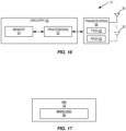
- FIG 16 is a schematic block diagram of the wireless device 12 (e.g., UE) according to some embodiments of the present disclosure.
- the wireless device 12 includes circuitry 20 comprising one or more processors 22 (e.g., Central Processing Units (CPUs), Application Specific Integrated Circuits (ASICs), Field Programmable Gate Arrays (FPGAs), Digital Signal Processors (DSPs), and/or the like) and memory 24.
- the wireless device 12 also includes one or more transceivers 26 each including one or more transmitters 28 and one or more receivers 30 coupled to one or more antennas 32.
- the functionality of the wireless device 12 may be implemented in hardware (e.g., via hardware within the circuitry 20 and/or within the processor(s) 22) or be implemented in a combination of hardware and software (e.g., fully or partially implemented in software that is, e.g., stored in the memory 24 and executed by the processor(s) 22).
- a computer program including instructions which, when executed by the at least one processor 22, causes the at least one processor 22 to carry out at least some of the functionality of the wireless device 12 (e.g., the functionality of a UE) according to any of the embodiments described herein is provided.
- a carrier containing the aforementioned computer program product is provided.
- the carrier is one of an electronic signal, an optical signal, a radio signal, or a computer readable storage medium (e.g., a non-transitory computer readable medium such as memory).
- FIG 17 is a schematic block diagram of the wireless device 12 (e.g., UE) according to some other embodiments of the present disclosure.
- the wireless device 12 includes one or more modules 34, each of which is implemented in software.
- the module(s) 34 provide the functionality of the wireless device 12 described herein.
- the modules(s) 34 may include a receiving/transmitting module operable to perform the function of step 102 of Figure 11 .
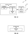
- FIG 18 is a schematic block diagram of a network node 36 (e.g., a radio access node 14 such as, for example, an eNB or gNB) or a core network node according to some embodiments of the present disclosure.
- the network node 36 includes a control system 38 that includes circuitry comprising one or more processors 40 (e.g., CPUs, ASICs, DSPs, FPGAs, and/or the like) and memory 42.
- the control system 38 also includes a network interface 44.
- the network node 36 is a radio access node 14
- the network node 36 also includes one or more radio units 46 that each include one or more transmitters 48 and one or more receivers 50 coupled to one or more antennas 52.
- the functionality of the network node 36 (specifically the functionality of the radio access node 14 or eNB) described above may be fully or partially implemented in software that is, e.g., stored in the memory 42 and executed by the processor(s) 40.
- FIG 19 is a schematic block diagram that illustrates a virtualized embodiment of the network node 36 (e.g., the radio access node 14 or a core network node) according to some embodiments of the present disclosure.
- a "virtualized" network node 36 is a network node 36 in which at least a portion of the functionality of the network node 36 is implemented as a virtual component (e.g., via a virtual machine(s) executing on a physical processing node(s) in a network(s)).
- the network node 36 optionally includes the control system 38, as described with respect to Figure 18 .
- the network node 36 is the radio access node 14
- the network node 36 also includes the one or more radio units 46, as described with respect to Figure 18 .
- the control system 38 (if present) is connected to one or more processing nodes 54 coupled to or included as part of a network(s) 56 via the network interface 44.
- the one or more radio units 46 (if present) are connected to the one or more processing nodes 54 via a network interface(s).
- all of the functionality of the network node 36 e.g., all of the functionality of the radio access node 14 or eNB) described herein may be implemented in the processing nodes 54.
- Each processing node 54 includes one or more processors 58 (e.g., CPUs, ASICs, DSPs, FPGAs, and/or the like), memory 60, and a network interface 62.
- functions 64 of the network node 36 are implemented at the one or more processing nodes 54 or distributed across the control system 38 (if present) and the one or more processing nodes 54 in any desired manner.
- some or all of the functions 64 of the network node 36 described herein are implemented as virtual components executed by one or more virtual machines implemented in a virtual environment(s) hosted by the processing node(s) 54.
- additional signaling or communication between the processing node(s) 54 and the control system 38 (if present) or alternatively the radio unit(s) 46 (if present) is used in order to carry out at least some of the desired functions.
- the control system 38 may not be included, in which case the radio unit(s) 46 (if present) communicates directly with the processing node(s) 54 via an appropriate network interface(s).
- higher layer functionality e.g., layer 3 and up and possibly some of layer 2 of the protocol stack
- the network node 36 may be implemented at the processing node(s) 54 as virtual components (i.e., implemented "in the cloud")
- lower layer functionality e.g., layer 1 and possibly some of layer 2 of the protocol stack
- radio unit(s) 46 and possibly the control system 38 may be implemented at the radio unit(s) 46 and possibly the control system 38.
- a computer program including instructions which, when executed by the at least one processor 40, 58, causes the at least one processor 40, 58 to carry out the functionality of the network node 36 or a processing node 54 according to any of the embodiments described herein is provided.
- a carrier containing the aforementioned computer program product is provided.
- the carrier is one of an electronic signal, an optical signal, a radio signal, or a computer readable storage medium (e.g., a non-transitory computer readable medium such as the memory 60).
- FIG 20 is a schematic block diagram of the network node 36 (e.g., the radio access node 14 or a core network node) according to some other embodiments of the present disclosure.
- the network node 36 includes one or more modules 66, each of which is implemented in software.
- the module(s) 66 provide the functionality of the network node 36 described herein.
- the module(s) 66 comprise, for example, a transmitting module operable to transmit the control information message as described above, e.g., with respect to step 100 of Figure 11 .
- 3GPP Third Generation Partnership Project eNB Enhanced or Evolved Node B 5G Fifth Generation ePDCCH enhanced Physical Downlink Control ASIC Application Specific Integrated Circuit Channel BLER Block Error Rate FDD Frequency Division Duplexing CP Cyclic Prefix FPGA Field Programmable Gate Array CPU Central Processing Unit gNB New Radio Base Station CRC Cyclic Redundancy Check HARQ Hybrid Automatic Repeat Request C-RNTI Cell Radio Network Temporary Identifier HTTP Hypertext Transfer Protocol CRS Cell Specific Reference Signal ID Identifier CSI Channel State Information LTE Long Term Evolution CSI-RS Channel State Information Reference LTE-A Long Term Evolution Advanced Signals MCS Modulation and Coding Scheme DCI Downlink Control Information MME Mobility Management Entity DMRS Demodulation Reference Signal ms Millisecond DSP Digital Signal Processor MTC Machine Type Communication NDI New Data Indicator SCEF Service Capability Exposure OFDM Orthogonal Frequency Division Function Multiplexing SC-FDMA Single Carrier-Frequency
Description
- The present disclosure relates to scheduling short transmission time interval transmissions in a wireless communications network.
- In Third Generation Partnership Project (3GPP) LTE systems, data transmissions in both downlink (i.e., from a network node or enhanced or evolved Node B (eNB) to a user device or User Equipment device (UE)) and uplink (from a user device or UE to a network node or eNB) are organized into radio frames of 10 milliseconds (ms), each radio frame consisting of ten equally-sized subframes of length Tsubframe = 1 ms, as shown in
Figure 1 . - LTE uses Orthogonal Frequency Division Multiplexing (OFDM) in the downlink and Single Carrier OFDM (SC-OFDM) in the uplink. The basic LTE downlink physical resource can thus be seen as a time-frequency grid as illustrated in
Figure 2 , where each resource element corresponds to one OFDM subcarrier during one OFDM symbol interval. - Furthermore, the resource allocation in LTE is typically described in terms of Resource Blocks (RBs), where a RB corresponds to one slot (0.5 ms) in the time domain and 12 contiguous subcarriers in the frequency domain. RBs are numbered in the frequency domain, starting with 0 from one end of the system bandwidth.
- Similarly, the LTE uplink resource grid is illustrated in
Figure 3 , where


- Downlink data transmissions from an eNB to a UE are dynamically scheduled, i.e., in each subframe the base station transmits control information about to which terminals data is transmitted and upon which RBs the data is transmitted, in the current downlink subframe or the downlink part (DwPTS) of the current special subframe. This control signaling is typically transmitted in the first 1, 2, 3, or 4 OFDM symbols in each subframe. A downlink subframe with three OFDM symbols as control is illustrated in
Figure 4 . - Similar to downlink, uplink transmissions from a UE to an eNB are also dynamically scheduled through the downlink control channel. When a UE receives an uplink grant in subframe n, it transmits data in the uplink at subframe n+k, where k=4 for a Frequency Division Duplexing (FDD) system and k varies for Time Division Duplexing (TDD) systems.
- In LTE, several physical channels and signals are supported for transmission of control information and data payloads. Some of the downlink physical channels and signals supported in LTE are:
- Physical Downlink Shared Channel (PDSCH)
- Physical Downlink Control Channel (PDCCH)
- Enhanced PDCCH (ePDCCH)
- Reference signals:
- ∘ Cell Specific Reference Signals (CRSs)
- ∘ Demodulation Reference Signal (DMRS) for PDSCH
- ∘ Channel State Information Reference Signals (CSI-RSs)
- PDSCH is used mainly for carrying user traffic data and higher layer messages in the downlink and is transmitted in a downlink subframe outside of the control region as shown in
Figure 4 . Both PDCCH and ePDCCH are used to carry Downlink Control Information (DCI) such as Physical RB (PRB) allocation, Modulation and Coding Scheme (MCS), precoder used at the transmitter, etc. - Existing physical layer downlink control channels, PDCCH and ePDCCH, are transmitted once per 1 ms subframe. Furthermore, a PDCCH is distributed over the whole carrier bandwidth, but is time multiplexed with PDSCH over the first 1-4 symbols in the subframe. An ePDCCH is distributed over the whole 1 ms subframe, but is frequency multiplexed with PDSCH and multiplexed onto one or multiple PRB pairs for localized and distributed transmission respectively. PDCCH has a common search space where all UEs need to detect common cell specific control information. Depending whether the UE has been configured for ePDCCH or not, it searches UE specific control information from UE search space of ePDCCH or PDCCH, respectively.
- It is also noted that the size of the PDCCH region can change dynamically on subframe basis. Recall that the size of the PDCCH region is signaled on the Physical Control Format Indicator Channel (PCFICH) in the beginning of the 1 ms subframe. The frequency domain allocation of the ePDCCH is semi-statically configured by means of higher layer signaling.
- Some of the uplink physical channels and signals supported in LTE are:
- Physical Uplink Shared Channel (PUSCH)
- Physical Uplink Control Channel (PUCCH)
- DMRS for PUSCH
- DMRS for PUCCH
- The PUSCH is used to carry uplink data or/and uplink control information from the UE to the eNB. The PUCCH is used to carry uplink control information from the UE to the eNB.
- The current control channels carry control information, referred to as DCI. There are several DCI formats which have different options depending on, e.g., configured transmission mode. The DCI format has a Cyclic Redundancy Check (CRC) which is scrambled by a UE identifier, such as a Cell Radio Network Temporary Identifier (C-RNTI), and when the CRCs match, after descrambling, a PDCCH with a certain DCI format has been detected. There are also identifiers that are shared by multiple terminals, such as the System Information Radio Network Temporary Identifier (SI-RNTI) which is used for transmission of system information.
- There are currently a number of different DCI formats, see 3GPP Technical Specification (TS) 36.212 for downlink resource
assignments including formats - Format 1: single codeword transmission
- ∘ 1 bit for indicating resource allocation type (
type 0 or type 1) - ∘

type 0 or type 1) - ∘ 3 bits for Hybrid Automatic Repeat Request (HARQ) process number (4 bits for TDD)
- ∘ 3 bits for New Data Indicator (NDI) and Redundancy Version (RV)
- ∘ 5 bits for MCS
- ∘ 1 bit for indicating resource allocation type (
- Format 1A, 1B, 1D
- ∘

- ∘ 3 bits for HARQ process number (4 bits for TDD)
- ∘ 3 bits for NDI and RV
- ∘ 5 bits for MCS
- ∘
-
Format 2, 2A, 2B, 2C, 2D: two codeword transmission- ∘

type 0 or type 1) - ∘ 3 bits for HARQ process number (4 bits for TDD)
- ∘ 2 x 3 bits for NDI and RV
- ∘ 2 x 5 bits for MCS
- ∘
- The DCI for a downlink scheduling assignment hence contains information on downlink data resource allocation in the frequency domain (the resource allocation), MCS, and HARQ process information. In case of carrier aggregation, information related to which carrier the PDSCH is transmitted on may be included as well.
- There are two main families of DCI formats for uplink grants,
DCI format 0 andDCI format 4. The latter is added inRelease 10 for supporting uplink spatial multiplexing. Several DCI format variants exist for bothDCI format 0 andDCI format 4 for various purposes, e.g. scheduling in unlicensed spectrum. - In general, the DCI for an uplink scheduling grant contains:
- Resource allocation information
- ∘ Carrier indicator
- ∘ Resource allocation type
- ∘ RB allocation
- RS and data related information
- ∘ MCS
- ∘ NDI
- ∘ Cyclic shift of the uplink DMRS
- ∘ Precoding information
- ∘ Transmit power control
- Other information
- ∘ Sounding Reference Signal (SRS) request
- ∘ Channel State Information (CSI) request
- ∘ Uplink index (for TDD)
-
∘ DCI format 0/1A indication (only inDCI format 0 and 1A) - ∘ Padding
- ∘ CRC scrambled with Radio Network Temporary Identifier (RNTI) of the terminal
- Packet data latency is one of the performance metrics that vendors, operators, and also end-users (via speed test applications) measure regularly. Latency measurements are done in all phases of a radio access network system lifetime, when verifying a new software release or system component, when deploying a system, and when the system is in commercial operation.
- Shorter latency than previous generations of 3GPP Radio Access Technologies (RATs) was one performance metric that guided the design of LTE. The end-users also now recognize LTE to be a system that provides faster access to the Internet and lower data latencies than previous generations of mobile radio technologies.
- Packet data latency is important not only for the perceived responsiveness of the system; it is also a parameter that indirectly influences the throughput of the system. Hypertext Transfer Protocol (HTTP) / Transmission Control Protocol (TCP) is the dominating application and transport layer protocol suite used on the Internet today. According to HTTP Archive (http://httparchive.org/trends.php), the typical size of HTTP based transactions over the Internet are in the range of a few tens of kilobytes up to one megabyte. In this size range, the TCP slow start period is a significant part of the total transport period of the packet stream. During TCP slow start the performance is latency limited. Hence, improved latency can rather easily be showed to improve the average throughput for this type of TCP based data transactions.
- Latency reductions could positively impact radio resource efficiency. Lower packet data latency could increase the number of transmissions possible within a certain delay bound; hence higher Block Error Rate (BLER) targets could be used for the data transmissions freeing up radio resources potentially improving the capacity of the system.
- One approach to latency reduction is the reduction of transport time of data and control signaling by addressing the length of a TTI. By reducing the length of a TTI and maintaining the bandwidth, the processing time at the transmitter and the receiver nodes is also expected to be reduced, due to less data to process within the TTI. In
LTE Release 8, a TTI corresponds to one subframe oflength 1 ms. One such 1 ms TTI is constructed by using 14 OFDM or Single Carrier- Frequency Division Multiple Access (SC-FDMA) symbols in the case of normal CP and 12 OFDM or SC-FDMA symbols in the case of extended CP. InLTE Release 14, a study item on latency reduction has been conducted, with the goal of specifying transmissions with shorter TTIs, such as a slot or a few symbols [3GPP TR 36.881]. A work item with the goal of specifying sTTI started in August 2016 [3GPP RP-162014]. - In LTE, a minimum required processing time is specified and applied for the downlink HARQ feedback timing and the uplink grant to uplink data delay. The latter is also called uplink scheduling timing. In case of sTTI, the minimum processing time will be reduced. For 2 OFDM symbol (2os) TTI, the minimum required processing timing could be k-1 sTTI, resulting in a timing of n+k. An example is k = 6 sTTI. This means that a UE receiving a downlink assignment for a downlink sTTI received in downlink sTTI n is expected to transmit the downlink HARQ feedback in uplink sTTI n+k. The same can be applied for the uplink scheduling timing. A UE receiving an uplink grant for an uplink sTTI in downlink sTTI n is expected to transmit the uplink data in uplink sTTI n+k.
- In TDD, the sTTI n+k may not be a valid uplink sTTI, in which case special rules for the timing can be defined but the minimum processing timing cannot be earlier than n+k. Similarly, in case of different downlink and uplink TTI lengths (for instance 2os TTI in downlink and slot TTI in uplink), the timing n+k may not always correspond to a valid sTTI in uplink, in which case special rules can be defined, such as HARQ feedback or uplink data should be sent in the earliest uplink sTTI after n+k.
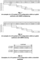
- An sTTI can be decided to have any duration in time and comprise resources on a number of OFDM or SC-FDMA symbols within a 1 ms subframe. As one example shown in
Figure 5 , the duration of the uplink sTTI is 0.5 ms, i.e. seven SC-FDMA symbols for the case with normal CP. As another example shown inFigure 6 , the durations of the uplink sTTIs within a subframe are of 2 or 3 symbols. Here, the "R" in the figures indicates the DMRS symbols, and "S" indicates the SRS symbols. - For uplink sTTI transmissions, shorter TTI lengths lead to larger DMRS overhead assuming at least one SC-FDMA symbol for transmitting DMRS within each sTTI for channel estimation. For very short TTI lengths, e.g. 2-symbol sTTI, the DMRS overhead can be 50%, leading to a significant performance loss in terms of throughput and spectral efficiency. In LTE, different DMRS design options have been considered to reduce the DMRS overhead:
- DMRS multiplexing: In case different UEs are scheduled in consecutive sTTIs, multiple UEs share the same SC-FMDA symbol for transmitting DMRS sequences, but having separate SC-FMDA symbols for the data.
- DMRS sharing: When the same UE is scheduled on consecutive sTTIs, the DMRS is not transmitted in each sTTI. Instead, the DMRS transmitted in the first sTTI will be shared by the following scheduled sTTIs for channel estimation.
- Example mechanisms depicted in
Figure 7 and Figure 8 would work both for DMRS sharing and DMRS multiplexing. For DMRS multiplexing, consider the example ofUE 1 scheduled insTTI 0 andUE 2 insTTI 1. InFigure 7 ,UE 1 will transmit data in SC-FDMA symbols symbol 2.UE 2 will transmit DMRS in the same symbol and data insymbols Figure 8 is used,UE 1 will transmit DMRS insymbol 0 and data insymbols UE 2 will transmit DMRS insymbol 0, be silent insymbols symbols - In case of DMRS sharing,
UE 1 is scheduled in bothsTTI 0 andsTTI 1. InFigure 7 ,UE 1 transmits data insymbols symbol 2. InFigure 8 ,UE 1 transmits data insymbols symbol 0. -
Figure 9 shows examples for 2 or 3-symbol downlink sTTI configurations within a subframe. Downlink transmissions can be CRS based or DMRS based. For DMRS based transmissions, the DMRS sharing option, as explained for uplink, can also be used for downlink sTTI transmissions to reduce the DMRS overhead. - Throughout this disclosure, short PDSCH (sPDSCH) and short PUSCH (sPUSCH) to denote the downlink and uplink physical shared channels with sTTIs, respectively. Similarly, short PDCCH (sPDCCH) is used to denote downlink physical control channels with sTTIs.
- To schedule an uplink or a downlink sTTI transmission, it is possible for the eNB to transmit the corresponding control information by using a new DCI format, referred to as short DCI (sDCI), in each downlink sTTI. The control channel carrying this sDCI can be either PDCCH or sPDCCH.
- Nokia et al.: "On scheduling of sPDSCH and sPUSCH", 3GPP Draft; R1-1704805, discloses details regarding Multi-sTTI scheduling. It is disclosed to allow for scheduling multiple sTTIs using a single DCI UL grant.
-
WO 2017/018758 A1 discloses a method and an apparatus for transmitting/receiving downlink control information. Downlink control information about a data channel may be transmitted through one of a plurality of decoding candidates. Depending on whether the data channel is based on a first sub-frame or a second sub-frame, the downlink control information is transmitted through one of the candidates for the first sub-frame or one of the candidates for the second sub-frame, from among the plurality of decoding candidates. The second sub-frame is shorter than the first sub-frame and can be set within the first sub-frame. - The present invention is set out in the independent claims whereas preferred embodiments and further implementations are outlined in the dependent claims, description and figures.
- The accompanying drawing figures incorporated in and forming a part of this specification illustrate several aspects of the disclosure, and together with the description serve to explain the principles of the disclosure.
-
Figure 1 illustrates an LTE time-domain structure; -
Figure 2 illustrates an LTE downlink physical resource; -
Figure 3 illustrates an LTE uplink resource grid; -
Figure 4 illustrates an LTE downlink subframe; -
Figure 5 illustrates an example of 7-symbol sTTI configuration with an uplink subframe; -
Figure 6 illustrates an example of a 2/3 symbol sTTI configuration with an uplink subframe; -
Figure 7 illustrates an example of 2/3 symbol sTTI configuration with DMRS multiplexing/sharing; -
Figure 8 illustrates an example of a 2/3 symbol sTTI configuration within an uplink subframe with DMRS multiplexing/sharing; -
Figure 9 illustrates examples of a 2/3 symbol sTTI configuration within a downlink subframe; -
Figure 10 illustrates one example of a wireless communication system in which embodiments of the present disclosure may be implemented; -
Figure 11 illustrates the operation of a radio access node and a wireless device according to some embodiments of the present disclosure; -
Figure 12 is an illustration of n+6 uplink scheduling timing for 2/3 symbol sTTI configurations in both uplink and downlink where sDCI can be transmitted in each downlink sTTI according to some embodiments of the present disclosure; -
Figure 13 illustrates an example of using 1 bit in the sDCI for indicating the DMRS configuration of the scheduled multiple sTTIs according to some embodiments of the present disclosure; -
Figure 14 illustrates an example of n+6 uplink scheduling timing for 2/3 symbol sTTI configurations in both uplink and downlink where sDCI for multi-sTTI scheduling can only be transmitted from PDCCH; -
Figure 15 illustrates an example of n+4 uplink scheduling timing for 2/3 symbol sTTI configurations in both uplink and downlink. Multi-sTTI DCI can only be transmitted from PDCCH according to some embodiments of the present disclosure; -
Figures 16 and 17 illustrate example embodiments of a wireless device; and -
Figures 18 through 20 illustrate example embodiments of a network node (e.g., a radio access node). - The invention is defined by the appended claims. The embodiments set forth below represent information to enable those skilled in the art to practice the embodiments and illustrate the best mode of practicing the embodiments. Upon reading the following description in light of the accompanying drawing figures, those skilled in the art will understand the concepts of the disclosure and will recognize applications of these concepts not particularly addressed herein. It should be understood that these concepts and applications fall within the scope of the disclosure.
- Radio Node: As used herein, a "radio node" is either a radio access node or a wireless device.
- Radio Access Node: As used herein, a "radio access node" or "radio network node" is any node in a radio access network of a cellular communications network that operates to wirelessly transmit and/or receive signals. Some examples of a radio access node include, but are not limited to, a base station (e.g., a New Radio (NR) base station (gNB) in a 3GPP Fifth Generation (5G) NR network or an eNB in a 3GPP LTE network), a high-power or macro base station, a low-power base station (e.g., a micro base station, a pico base station, a home eNB, or the like), and a relay node.
- Core Network Node: As used herein, a "core network node" is any type of node in a core network. Some examples of a core network node include, e.g., a Mobility Management Entity (MME), a Packet Data Network Gateway (P-GW), a Service Capability Exposure Function (SCEF), or the like.
- Wireless Device: As used herein, a "wireless device" is any type of device that has access to (i.e., is served by) a cellular communications network by wirelessly transmitting and/or receiving signals to a radio access node(s). Some examples of a wireless device include, but are not limited to, a UE in a 3GPP network and a Machine Type Communication (MTC) device.
- Network Node: As used herein, a "network node" is any node that is either part of the radio access network or the core network of a cellular communications network/system.
- Short Transmission Time Interval (sTTI): As used herein, a "sTTI" is a transmission duration that is shorter than a nominal transmission duration. In LTE, the nominal transmission duration is called a subframe and is composed of 14 OFDM/SC-FDMA symbols with normal cyclic prefix. In LTE, a 2 or 3 OFDM symbol long transmission can also be referred to as subslot transmission, while a 7 OFDM symbol long transmission can also be referred to as slot transmission. In NR, the nominal transmission duration is called a slot and is composed of 14 OFDM/SC-FDMA symbols with normal cyclic prefix. In NR, a transmission duration of less than 14 OFDM symbols can also be referred to as PDSCH/PUSCH type B (mini-slot/non-slot based transmission) in NR.
- Note that the description given herein focuses on a 3GPP cellular communications system and, as such, 3GPP terminology or terminology similar to 3GPP terminology is oftentimes used. However, the concepts disclosed herein are not limited to a 3GPP system.
- Note that, in the description herein, reference may be made to the term "cell;" however, particularly with respect to 5G NR concepts, beams may be used instead of cells and, as such, it is important to note that the concepts described herein are equally applicable to both cells and beams.
- Using existing technology, in order to schedule an uplink or a downlink sTTI transmission, the eNB transmits corresponding control information using a new DCI format, referred to as short DCI (sDCI), in each downlink sTTI. The control channel carrying this sDCI can be either PDCCH or sPDCCH. However, transmitting sDCI in every single sTTI represents a high control overhead, especially for 2/3-symbol sTTI. This means that the number of available REs to be used for data transmission is reduced due to the RE utilized for the sDCI transmissions. This overhead can be seen as unnecessary when a UE is scheduled in consecutive sTTIs within a 1 ms subframe under similar channel conditions.
- For DMRS sharing, a UE is scheduled with multiple consecutive sTTIs, and the DMRS is only transmitted in the first sTTI to reduce the overhead. If an sDCI is intended for scheduling only a single sTTI transmission, then multiple scheduling assignments/grants should be sent for scheduling these consecutive sTTls. This will increase the control signaling overhead.
- In addition, it can cause a reliability issue for DMRS sharing. For example, consider the uplink DMRS sharing case, where the UE misses the first uplink grant, so it will not transmit DMRS. Then, the eNB will not be able to decode the following sTTI transmissions due to lack of channel information.
- Different signaling methods for multi-sTTI scheduling for both uplink and downlink sTTI transmissions are disclosed herein. Embodiments of the present disclosure support the scheduling of multiple sTTI transmissions for both downlink and uplink transmissions - CRS based for downlink and DMRS based for downlink and uplink - to reduce both the DMRS overhead based on DMRS sharing and control signaling overhead from the sDCI transmissions. In addition, embodiments of the present disclosure provide the same reliability for DMRS sharing as for the single sTTI transmission for downlink and uplink.
-
Figure 10 illustrates one example of a wireless communication network 10 (e.g., an LTE (e.g., LTE Advanced (LTE-A), LTE-Pro, or an enhanced version of LTE) or 5G NR network) in which embodiments of the present disclosure may be implemented. As illustrated, a number of wireless devices 12 (e.g., UEs) wirelessly transmit signals to and receive signals from radio access nodes 14 (e.g., eNBs or gNBs, which is a 5G NR base station), each serving one ormore cells 16. Theradio access nodes 14 are connected to acore network 18. -
Figure 11 illustrates the operation of theradio access node 14 and thewireless device 12 according to some embodiments of the present disclosure. In general, this process is performed by the radio access node 14 (or more generally a network node) to provide scheduling of multiple sTTI transmissions in uplink and/or downlink. As illustrated, theradio access node 14 transmits a control information message to the wireless device 12 (step 100). The control information message is for one or more scheduled sTTI transmissions, which may be uplink transmissions or downlink transmissions. The control information message includes scheduling information that indicates the sTTI(s) for the scheduled sTTI transmission(s) and/or an indication of a timing for the scheduled sTTI transmission(s) and/or an indication of a DMRS configuration for the scheduled sTTI transmission(s). Further, as discussed below, in some embodiments, the control information message is for two or more scheduled sTTI transmissions, e.g., in two or more consecutive sTTIs in the time domain. - In some embodiments, the control information message includes scheduling information that indicates the sTTI(s) for the scheduled sTTI transmission(s), where the scheduling information is uplink scheduling information and/or downlink scheduling information. In other words, the scheduled sTTI transmission(s) are uplink transmission(s) or downlink transmission(s). In some embodiments, the control information includes scheduling information that indicates two or more sTTIs for two or more sTTI transmissions, respectively, where the two or more sTTIs are consecutive in the time domain.
- In some embodiments, the control information message is referred to as sDCI, and the sDCI can be transmitted from in both PDCCH and sPDCCH. Here, a sPDCCH is used for scheduling both uplink and downlink sTTI transmissions. A sPDCCH can be transmitted in each downlink sTTI, except for the legacy control region. Further, in some embodiments, the sTTls for the scheduled sTTI transmissions (sometimes referred to herein as scheduled sTTIs) are determined by a fixed scheduling timing and a bit field of the sDCI indicating the number of scheduled sTTls.
- In some embodiments, a DMRS configuration, including both the number of DMRS symbols and the position of the DMRS symbols, is preconfigured or configured by signaling (e.g., Radio Resource Control (RRC) signaling), for each possible combination of multiple scheduled sTTls. In some other embodiments, the DMRS configuration for the scheduled sTTIs, including both the number of DMRS symbols and the position of the DMRS symbols, is indicated in the sDCI (e.g., indicated by a separate bit field of the sDCI).
- In some embodiments, the control information message (for two or more scheduled sTTI transmissions scheduled on two or more sTTIs respectively) is transmitted only once per subframe. Further, in some embodiments, the control information message is carried only on PDCCH.
- In some embodiments, the control information message is transmitted only once per slot. For instance, it is carried on PDCCH for the first slot in the subframe, and on the first sPDCCH of the second slot in the subframe. Further, in some embodiments, the possible combinations of multiple scheduled sTTIs are predefined, and a bit field of the sDCI together with a fixed scheduling timing are used to explicitly indicate the selected combination of sTTIs for multi-sTTI transmissions.
- In some embodiments, the scheduled sTTIs are determined by a bit field of the sDCI indicating the number of scheduled sTTIs together with a bit field of the sDCI indicating the timing of at least the first scheduled sTTI.
- Upon receiving the control information message, the
wireless device 12 receives (or downlink embodiments) or transmits (for uplink embodiments) the scheduled sTTI transmissions in accordance with the control information message (step 102). In other words, thewireless device 12 performs data decoding (downlink) or data transmission (uplink) based on the received control information message. - In the following, some examples are provided for how to signal multiple scheduled sTTI transmissions in both uplink and downlink.
- In a first embodiment, the control information message, which is referred to as sDCI, can be transmitted from each downlink sTTI. A signaling example is presented below, assuming only consecutive sTTIs can be scheduled, and the maximum number of scheduling sTTIs is three. However, since this is only an example, the present disclosure is not limited thereto.
-
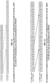
Figure 12 shows the earliest uplink sTTI that can be scheduled from an uplink grant sent in a downlink sTTI considering the n+6 uplink scheduling timing for 2 or 3-symbol sTTI transmissions. For instance, assuming that there are 6 sTTIs per subframe, if an uplink grant is sent indownlink sTTI 0 in subframe n, this grant can scheduleuplink sTTI 0 in subframe n+1 at the earliest. If the uplink grant is a multi-sTTI scheduling grant sent indownlink sTTI 0 in subframe n, this grant could scheduleuplink sTTI 0 and uplinksTTI 1 in subframe n+1 for instance (but not earlier thanuplink sTTI 0 in subframe n+1). - Considering the n+6 uplink scheduling timing for 2 or 3-symbol sTTI transmissions shown in
Figure 12 , Table 1 gives the mapping of the value of the 1-bit field in the sDCI to the scheduled multiple consecutive sTTls.Table 1 An example of using 1 bit in the sDCI for uplink multi-sTTI scheduling with n+6 scheduling timing DL index (sDCI) on subframe (n) bit field Nrof_sTTI Number of sTTIs Scheduled UL sTTI index On subframe (n+1) On subframe (n+2) 0 0 2 0 and 1 - 0 1 3 0 and 1 and 2 - 1 0 2 1 and 2 - 1 1 3 1 and 2 and 3 - 2 0 2 2 and 3 - 2 1 3 2 and 3 and 4 - 3 0 2 3 and 4 - 3 1 3 3 and 4 and 5 - 4 0 2 4 and 5 - 4 1 3 4 and 5 0 5 0 2 5- 0 5 1 3 5 0 and 1 - For downlink scheduling, the same approach can be applied, except that the scheduled downlink sTTI does not have the n+6 scheduling timing constraint. Instead, the downlink scheduling timing can be down to n+0, meaning that the earliest downlink sTTI that can be scheduled by a downlink assignment found in downlink sTTI n is downlink sTTI n. Table 1A gives the mapping of the value of the 1-bit field in the sDCI to the scheduled multiple consecutive sTTIs.
Table 1A: An example of using 1 bit in the sDCI for downlink multi-sTTI scheduling with n+0 scheduling timing DL index (sDCI) on subframe (n) bit field Nrof_sTTI Number of sTTIs Scheduled DL sTTI index On subframe (n) On subframe (n+1) 0 0 2 0 and 1 - 0 1 3 0 and 1 and 2 - 1 0 2 1 and 2 - 1 1 3 1 and 2 and 3 - 2 0 2 2 and 3 - 2 1 3 2 and 3 and 4 - 3 0 2 3 and 4 - 3 1 3 3 and 4 and 5 - 4 0 2 4 and 5 - 4 1 3 4 and 5 0 5 0 2 5- 0 5 1 3 5 0 and 1 - The DMRS configuration for each scheduled multi-sTTI combination can be preconfigured for both uplink transmissions and DMRS-based downlink transmissions. For example, for uplink multi-sTTI scheduling, the DMRS is always placed at the first SC-FDMA symbol of the first scheduled uplink sTTI. As another example, for downlink multi-sTTI scheduling, the DMRS is always placed at the first OFDM symbol of the first scheduled downlink sTTI. It is also possible to re-configure the DMRS position by RRC signaling to adapt the channel conditions.
- Another way is to use a separate bit field in the sDCI for indicating the DMRS configuration, so that the DMRS configuration can dynamically adapt to the channel conditions.
Figure 13 illustrates an example of how to use 1 bit in the sDCI for indicating the DMRS configuration for some multi-sTTI combinations in uplink. - In the downlink, there should always be DMRS symbols in the first sTTI of the series of sTTIs scheduled with multi-sTTI scheduling. This enables the UE to start decoding the first sTTI of the series before the other sTTIs, as in case of single sTTI scheduling, and send the corresponding downlink HARQ feedback after the predefined downlink HARQ feedback delay. A dynamic DMRS configuration can allow changing the periodicity of the DMRS insertion in the series of scheduled sTTIs starting from the first sTTI. For instance, if the field for DMRS configuration is set to 0, only the first sTTI of the series of scheduled sTTIs contains DMRS. If the field is set to 1, every second sTTI of the series contains DMRS, starting from the first sTTI.
- In the downlink, the DMRS configuration field can also have a different interpretation depending on the number of scheduled sTTIs in the series. For instance, if the field for DMRS configuration is set to 0 and the number of scheduled sTTI in the series is less than the number of sTTIs in a subframe, only the first sTTI of the series of scheduled sTTIs contains DMRS. If the field for DMRS configuration is set to 0 and the number of scheduled sTTI in the series equals the number of sTTIs of a subframe (i.e. 6 sTTIs for LTE 2os TTI), the first sTTI of each LTE slot contains DMRS. If the field is set to 1, every second sTTI of the series contains DMRS, starting from the first sTTI.
- In a second embodiment, sDCI for multi-sTTI scheduling can only be transmitted from PDCCH. In other words, in order to reduce the signaling overhead and the blind decoding complexity at the UE (e.g., the wireless device 12), it can be restricted that the sDCI for multi-sTTI scheduling, defined as multi-sTTI DCI, is only transmitted from PDCCH. In the following, two signaling examples are given, assuming that only consecutive sTTIs can be scheduled in the multi-sTTI DCI. However, since this is only an example, the present disclosure is not limited thereto.
- Given this method, the UE (e.g., the wireless device 12) monitors the multi-sTTI DCI in PDCCH only. Consequently, the UE does not expect DCI for multi-sTTI scheduling on sPDCCH. But, it does monitor both single and multi-sTTI DCls in PDCCH. Additionally, if a multi-sTTI scheduling for downlink/uplink assignment is found in PDCCH, the UE would not need to search for an sDCI in the already scheduled sTTls. For the sTTIs which are not scheduled by the multi-sTTI DCI transmitted in PDCCH, the UE should monitor sDCI.
- In a first variation of the second embodiment, a single bit field is included in the control information for indicating the scheduled sTTls. Considering the n+6 uplink scheduling timing for 2 or 3-symbol sTTI transmissions shown in
Figure 14 , Table 2 lists all the possible combinations of multiple consecutive sTTIs that can be scheduled by sending a multi-sTTI DCI from the PDCCH. It can be seen that 4 bits are sufficient for indicating all possible combinations for the uplink or downlink multi-sTTI scheduling. Note that in this case, the downlink sTTIs belong to the same subframe where the multi-sTTI DCI is transmitted, while uplink sTTIs are in the next subframe. - The same method can be used for other uplink scheduling timing as well. For example, as shown in
Figure 15 and Table 3, considering the n+4 scheduling timing, it is also possible to use 4 bits to indicate the scheduled multiple sTTls. Note that in this case, thesTTI 4 andsTTI 5 are in the same subframe where the multi-sTTI DCI is transmitted, whilesTTI Table 2: A bit field of sDCI for uplink multi-sTTI scheduling with n+6 scheduling timing or downlink multi-sTTI with n+0 scheduling timing. bit field Scheduled UL/DL sTTI index 0 0 0 0 0 and 1 0 0 0 1 1 and 2 0 0 1 0 2 and 3 0 0 1 1 3 and 4 0 1 0 0 4 and 5 0 1 0 1 0 and 1 and 2 0 1 1 0 1 and 2 and 3 0 1 1 1 2 and 3 and 4 1 0 0 0 3 and 4 and 5 1 0 0 1 0 and 1 and 2 and 3 1 0 1 0 1 and 2 and 3 and 4 1 0 1 1 2 and 3 and 4 and 5 1 1 0 0 0 and 1 and 2 and 3 and 4 1 1 0 1 1 and 2 and 3 and 4 and 5 1 1 1 0 0 and 1 and 2 and 3 and 4 and 5 1 1 1 1 reserved Table 3: A bit field of sDCI for uplink multi-sTTI scheduling with n+4 scheduling timing bit field Scheduled UL sTTI index 0 0 0 0 4 and 5 0 0 0 1 5 and 0 0 0 1 0 0 and 1 0 0 1 1 1 and 2 0 1 0 0 2 and 3 0 1 0 1 4 and 5 and 0 0 1 1 0 5 and 0 and 1 0 1 1 1 0 and 1 and 2 1 0 0 0 1 and 2 and 3 1 0 0 1 4 and 5 and 0 and 1 1 0 1 0 5 and 0 and 1 and 2 1 0 1 1 0 and 1 and 2 and 3 1 1 0 0 4 and 5 and 0 and 1 and 2 1 1 0 1 5 and 0 and 1 and 2 and 3 1 1 1 0 4 and 5 and 0 and 1 and 2 and 3 1 1 1 1 reserved - In practice, not all these 15 combinations shown in Table 1 and Table 2 are needed. For example, to keep good channel estimation performance, the maximum number of consecutive sTTIs that is allowed can be limited to 3. In this case, only 3 bits are needed for the signaling. It is also possible to reduce the signaling overhead by removing some combinations, e.g., the ones that all scheduled sTTIs are not within the same subframe, or not within the same slot.
- As an enhancement of the described method, the reserved combination (e.g., 1111) can be reused to convey signaling for a single sTTI scheduling. Thereby, the eNB can schedule either single or multiple sTTI using same multi-sTTI DCI format in PDCCH. Given that, the UE may monitor only multi-sTTI (downlink and uplink) DCIs on PDCCH. For instance, if the bit field is set to 1111 in downlink multi-sTTI DCI, the scheduled downlink sTTI index is 0. if the bit field is set to 1111 in uplink multi-sTTI DCI, the scheduled uplink sTTI index is 4 in same subframe or 0 in next subframe for n+4 and n+6 uplink scheduling timing, respectively. The methods on DMRS configuration discussed above with respect to
method 1 apply formethod 2 as well. For the sTTIs which are not scheduled by the multi-sTTI DCI transmitted in PDCCH, the UE should monitor sDCI. - In a second variation of the second embodiment, two different bit fields are included in the control information and used to indicate the scheduled sTTls. In other words, another method for signaling the scheduled multiple sTTIs is by using two separate bit fields, one for indicating the timing, i.e., n+k+Δl, of the first scheduled sTTI, and the other field for indicating the number of the scheduling sTTIs. Table 4 illustrates an example of using this signaling method, assuming n+6 minimum scheduling timing. Note that in this case, the downlink sTTIs belong to the same subframe where the multi-sTTI DCI is transmitted, while uplink sTTI are in the next subframe.
- Similarly, the number of required signaling bits can be reduced by removing some combinations.
Table 4 An example of using two different bit fields of the sDCI for uplink and downlink multi-sTTI scheduling with n+k+ΔI scheduling timing and k=6 Bit field for Number_of_sTTI Bit field for timing Number of sTTIs Timing offset, ΔI Scheduled UL/DL sTTI index 0 0 0 0 0 0 2 0 0 and 1 0 0 0 0 0 1 2 1 1 and 2 0 0 0 0 1 0 2 2 2 and 3 0 0 0 0 1 1 2 3 3 and 4 0 0 0 1 0 0 2 4 4 and 5 0 0 1 0 0 0 3 0 0 and 1 and 2 0 0 1 0 0 1 3 1 1 and 2 and 3 0 0 1 0 1 0 3 2 2 and 3 and 4 0 0 1 0 1 1 3 3 3 and 4 and 5 0 1 0 0 0 0 4 0 0 and 1 and 2 and 3 0 1 0 0 0 1 4 1 1 and 2 and 3 and 4 0 1 0 0 1 0 4 2 2 and 3 and 4 and 5 0 1 1 0 0 0 5 0 0 and 1 and 2 and 3 and 4 0 1 1 0 0 1 5 1 1 and 2 and 3 and 4 and 5 1 0 0 0 0 0 6 0 0 and 1 and 2 and 3 and 4 and 5 others others reserved reserved reserved - Similar to the enhancement in the first variation of the second embodiment, single sTTI scheduling can be supported by the multi-sTTI DCI. The UE may monitor only multi-sTTI (downlink/uplink) DCI in PDCCH. For the sTTIs which are not scheduled by the multi-sTTI DCI transmitted in PDCCH, the UE should monitor sDCI.
- In a third embodiment, slot-based multi-sTTI scheduling DCI is provided. The third embodiment allows scheduling a minimum of one complete slot. The third embodiment can be seen as a subset of the first and second embodiments. Using slot-based multi-sTTI DCI, the eNB can schedule all sTTIs in the first slot, all sTTIs in the second slot, or all sTTIs in both slots. Table 5 shows an example.
- Multi-sTTI DCI can be limited to PDCCH or additionally to the first sTTI in the second slot of the subframe.
- In case of six sTTIs per subframe and an uplink scheduling timing of n+6, the third embodiment is well suited for scheduling multiple uplink sTTIs of a slot from the first downlink sTTI of a slot. The third embodiment can however also be applied in case that the uplink scheduling timing k in n+k does not correspond to the number of sTTIs per subframe, p (i.e., p is not equal to k). In that case, two alternatives exist. In the first alternative, a rule is defined for the UEs so that a multi-sTTI uplink grant received in a downlink sTTI n indicates scheduling of sTTIs of slots starting at the earliest at or after the uplink scheduling timing n+k. In the second alternative, a Timing offset, Δl can be signaled in the uplink multi-sTTI DCI to adjust the timing of the sTTI scheduled to start from the next possible slot after n+k.
Table 5: An example of using slot based scheduling sDCI for uplink and downlink multi-sTTI scheduling with respectively n+6 and n+0 scheduling timing. sDCI index on subframe (n) Bit field Scheduled DL sTTI in slot index Scheduled UL sTTI in slot index on subframe (n) on subframe (n+1) on subframe (n+1) on subframe (n+2) 0 00 0 - 0 - 0 01 1 - 1 - 0 10 0 and 1 - 0 and 1 - 0 Reserved Reserved Reserved Reserved Reserved 3 00 1 - 1 - 3 01 - 0 - 0 3 10 1 0 1 0 3 Reserved Reserved Reserved Reserved Reserved - Single sTTI scheduling can be supported by the multi-sTTI DCI by reusing the reserved combination. So that the UE may monitor only multi-sTTI (downlink/uplink) DCI in PDCCH and the first sTTI of the second slot. For the sTTIs within each slot which are not scheduled by the respective multi-sTTI DCI, the UE should monitor sDCI.
- Other aspects of the present disclosure relating to multi-sTTI DCI will now be described. To limit the number of additional bits in the DCI for multi-sTTI scheduling, i.e. multi-sTTI DCI, restrictions such as same MCS, Precoding Matrix Indicator (PMI), and resource allocation are valid options. Those fields are not expected to change significantly within consecutive sTTls. The following fields are not extended per sTTI; instead, the same value is applied for all scheduled sTTls:
- Resource allocation header (
resource allocation type 0 / type 1) - Resource block assignment
- TCP command for PUCCH
- Downlink assignment index
- HARQ process number
- MCS/ TB
- Precoding information depending on TM
- On the other hand, RV and NDI fields should be specified per sTTI to enable multiplexing of new data and retransmissions on different sTTIs using one DCI. Thereby, the length of NDI field is equivalent to the configured maximum number of sTTI scheduled by DCI for multi-sTTI scheduling.
- As for the HARQ Identifier (ID) number, the DCI for the multi-subframe scheduling includes the HARQ process number for the first subframe (i) in the scheduled burst. The HARQ process number for the remaining subframe in (i+1,... N-1) are decided based on the following equation:
- mod(nHARQ_ID + i,NHARQ)
- the value of n HARQ_ID is determined by the HARQ process number field in the corresponding DCI format
- the value of NHARQ is the number of configured HARQ processes.
- the value of N is determined by the number of scheduled sTTI in the corresponding DCI format.
-
Figure 16 is a schematic block diagram of the wireless device 12 (e.g., UE) according to some embodiments of the present disclosure. As illustrated, thewireless device 12 includescircuitry 20 comprising one or more processors 22 (e.g., Central Processing Units (CPUs), Application Specific Integrated Circuits (ASICs), Field Programmable Gate Arrays (FPGAs), Digital Signal Processors (DSPs), and/or the like) andmemory 24. Thewireless device 12 also includes one ormore transceivers 26 each including one ormore transmitters 28 and one ormore receivers 30 coupled to one ormore antennas 32. In some embodiments, the functionality of the wireless device 12 (e.g., the functionality of a UE) described herein may be implemented in hardware (e.g., via hardware within thecircuitry 20 and/or within the processor(s) 22) or be implemented in a combination of hardware and software (e.g., fully or partially implemented in software that is, e.g., stored in thememory 24 and executed by the processor(s) 22). - In some embodiments, a computer program including instructions which, when executed by the at least one
processor 22, causes the at least oneprocessor 22 to carry out at least some of the functionality of the wireless device 12 (e.g., the functionality of a UE) according to any of the embodiments described herein is provided. In some embodiments, a carrier containing the aforementioned computer program product is provided. The carrier is one of an electronic signal, an optical signal, a radio signal, or a computer readable storage medium (e.g., a non-transitory computer readable medium such as memory). -
Figure 17 is a schematic block diagram of the wireless device 12 (e.g., UE) according to some other embodiments of the present disclosure. Thewireless device 12 includes one ormore modules 34, each of which is implemented in software. The module(s) 34 provide the functionality of thewireless device 12 described herein. For example, the modules(s) 34 may include a receiving/transmitting module operable to perform the function ofstep 102 ofFigure 11 . -
Figure 18 is a schematic block diagram of a network node 36 (e.g., aradio access node 14 such as, for example, an eNB or gNB) or a core network node according to some embodiments of the present disclosure. As illustrated, thenetwork node 36 includes acontrol system 38 that includes circuitry comprising one or more processors 40 (e.g., CPUs, ASICs, DSPs, FPGAs, and/or the like) andmemory 42. Thecontrol system 38 also includes anetwork interface 44. In embodiments in which thenetwork node 36 is aradio access node 14, thenetwork node 36 also includes one ormore radio units 46 that each include one ormore transmitters 48 and one ormore receivers 50 coupled to one ormore antennas 52. In some embodiments, the functionality of the network node 36 (specifically the functionality of theradio access node 14 or eNB) described above may be fully or partially implemented in software that is, e.g., stored in thememory 42 and executed by the processor(s) 40. -
Figure 19 is a schematic block diagram that illustrates a virtualized embodiment of the network node 36 (e.g., theradio access node 14 or a core network node) according to some embodiments of the present disclosure. As used herein, a "virtualized"network node 36 is anetwork node 36 in which at least a portion of the functionality of thenetwork node 36 is implemented as a virtual component (e.g., via a virtual machine(s) executing on a physical processing node(s) in a network(s)). As illustrated, thenetwork node 36 optionally includes thecontrol system 38, as described with respect toFigure 18 . In addition, if thenetwork node 36 is theradio access node 14, thenetwork node 36 also includes the one ormore radio units 46, as described with respect toFigure 18 . The control system 38 (if present) is connected to one ormore processing nodes 54 coupled to or included as part of a network(s) 56 via thenetwork interface 44. Alternatively, if thecontrol system 38 is not present, the one or more radio units 46 (if present) are connected to the one ormore processing nodes 54 via a network interface(s). Alternatively, all of the functionality of the network node 36 (e.g., all of the functionality of theradio access node 14 or eNB) described herein may be implemented in theprocessing nodes 54. Eachprocessing node 54 includes one or more processors 58 (e.g., CPUs, ASICs, DSPs, FPGAs, and/or the like),memory 60, and anetwork interface 62. - In this example, functions 64 of the network node 36 (e.g., the functions of the
radio access node 14 or eNB) described herein are implemented at the one ormore processing nodes 54 or distributed across the control system 38 (if present) and the one ormore processing nodes 54 in any desired manner. In some particular embodiments, some or all of thefunctions 64 of thenetwork node 36 described herein are implemented as virtual components executed by one or more virtual machines implemented in a virtual environment(s) hosted by the processing node(s) 54. As will be appreciated by one of ordinary skill in the art, additional signaling or communication between the processing node(s) 54 and the control system 38 (if present) or alternatively the radio unit(s) 46 (if present) is used in order to carry out at least some of the desired functions. Notably, in some embodiments, thecontrol system 38 may not be included, in which case the radio unit(s) 46 (if present) communicates directly with the processing node(s) 54 via an appropriate network interface(s). - In some particular embodiments, higher layer functionality (e.g.,
layer 3 and up and possibly some oflayer 2 of the protocol stack) of thenetwork node 36 may be implemented at the processing node(s) 54 as virtual components (i.e., implemented "in the cloud") whereas lower layer functionality (e.g.,layer 1 and possibly some oflayer 2 of the protocol stack) may be implemented in the radio unit(s) 46 and possibly thecontrol system 38. - In some embodiments, a computer program including instructions which, when executed by the at least one
processor processor network node 36 or aprocessing node 54 according to any of the embodiments described herein is provided. In some embodiments, a carrier containing the aforementioned computer program product is provided. The carrier is one of an electronic signal, an optical signal, a radio signal, or a computer readable storage medium (e.g., a non-transitory computer readable medium such as the memory 60). -
Figure 20 is a schematic block diagram of the network node 36 (e.g., theradio access node 14 or a core network node) according to some other embodiments of the present disclosure. Thenetwork node 36 includes one ormore modules 66, each of which is implemented in software. The module(s) 66 provide the functionality of thenetwork node 36 described herein. In some embodiments, the module(s) 66 comprise, for example, a transmitting module operable to transmit the control information message as described above, e.g., with respect to step 100 ofFigure 11 . - The following acronyms are used throughout this disclosure.
3GPP Third Generation Partnership Project eNB Enhanced or Evolved Node B 5G Fifth Generation ePDCCH enhanced Physical Downlink Control ASIC Application Specific Integrated Circuit Channel BLER Block Error Rate FDD Frequency Division Duplexing CP Cyclic Prefix FPGA Field Programmable Gate Array CPU Central Processing Unit gNB New Radio Base Station CRC Cyclic Redundancy Check HARQ Hybrid Automatic Repeat Request C-RNTI Cell Radio Network Temporary Identifier HTTP Hypertext Transfer Protocol CRS Cell Specific Reference Signal ID Identifier CSI Channel State Information LTE Long Term Evolution CSI-RS Channel State Information Reference LTE-A Long Term Evolution Advanced Signals MCS Modulation and Coding Scheme DCI Downlink Control Information MME Mobility Management Entity DMRS Demodulation Reference Signal ms Millisecond DSP Digital Signal Processor MTC Machine Type Communication NDI New Data Indicator SCEF Service Capability Exposure OFDM Orthogonal Frequency Division Function Multiplexing SC-FDMA Single Carrier-Frequency Division PCFICH Physical Control Format Indicator Multiple Access Channel SC-OFDM Single Carrier-Orthogonal Frequency PDCCH Physical Downlink Control Channel Division Multiplexing PDSCH Physical Downlink Shared Channel SI-RNTI System Information Radio Network P-GW Packet Data Network Gateway Temporary Identifier PMI Preceding Matrix Indicator sPDCCH Short Physical Downlink Control PRB Physical Resource Block Channel PUCCH Physical Uplink Control Channel sPDSCH Short Physical Downlink Shared Channel PUSCH Physical Uplink Shared Channel sPUSCH Short Physical Uplink Shared Channel RAT Radio Access Technology SRS Sounding Reference Signal RB Resource Block sTTI Short Transmission Time Interval RE Resource Element TCP Transmission Control Protocol RNTI Radio Network Temporary Identifier TDD Time Division Duplexing RRC Radio Resource Control TS Technical Specification RV Redundancy Version TTI Transmission Time Interval sDCI Short Downlink Control Information UE User Equipment - Those skilled in the art will recognize improvements and modifications to the embodiments of the present disclosure. All such improvements and modifications are considered within the scope of the concepts disclosed herein.
Claims (14)
- A method of operation of a network node (14) of a wireless communication network (10) for scheduling multiple short Transmission Time Interval, sTTI, transmissions, comprising:transmitting (100) a control information message to a wireless device (12) for two or more sTTI transmissions;wherein the control information message comprises:downlink scheduling information indicating two or more scheduled downlink sTTIs for the two or more sTTI transmissions, the downlink scheduling information including an indication of a timing for the two or more scheduled downlink sTTIs for the two or more sTTI transmissions and an indication of a number of the scheduled downlink sTTIs; and optionallyuplink scheduling information indicating two or more scheduled uplink sTTIs for the two or more sTTI transmissions, the uplink scheduling information including an indication of a timing for the two or more scheduled uplink sTTIs for the two or more sTTI transmissions and/or an indication of a Demodulation Reference Signal, DMRS, configuration for the two or more scheduled uplink sTTIs for the two or more sTTI transmissions.
- The method of claim 1 wherein the two or more scheduled downlink sTTIs are consecutive in the time domain, and optionally wherein the two or more scheduled uplink sTTIs are consecutive in the time domain.
- The method of claim 1 or 2 wherein the control information message is transmitted on either a physical downlink control channel or a short physical downlink control channel.
- The method of claim 3 wherein a short physical downlink control channel is transmitted in each downlink sTTI transmission, except for a legacy control region.
- The method of any one of claims 1 to 4 wherein the control information message comprises a bit field that indicates the number of scheduled downlink sTTIs.
- The method of claim 5 wherein the two or more scheduled downlink sTTIs are determined by a fixed scheduling timing and the bit field of the control information message that indicates the number of scheduled downlink sTTIs.
- The method of claim 5 wherein:a plurality of possible combinations of two or more downlink sTTIs are predefined; andthe bit field comprised in the control information message together with an index of a downlink sTTI transmission containing the control information message explicitly indicates one of the plurality of possible combinations of two or more downlink sTTIs as a selected combination of downlink sTTIs for the two or more sTTI transmissions.
- The method of claim 5 wherein:a plurality of possible combinations of two or more downlink sTTIs are predefined; andthe bit field comprised in the control information message explicitly indicates one of the plurality of possible combinations of two or more downlink sTTIs as a selected combination of downlink sTTIs for the two or more sTTI transmissions and, optionally,wherein the control information message is comprised in a physical downlink control channel for a Transmission Time Interval, TTI, that comprises a plurality of sTTIs.
- The method of claim 7 or 8 wherein a Demodulation Reference Signal, DMRS, configuration for each of the plurality of possible combinations of two or more sTTI transmissions is preconfigured orwherein the control information message comprises a second bit field that indicates a Demodulation Reference Signal, DMRS, configuration for the two or more sTTI transmissions orwherein the control information message comprises a second bit field that, together with the number of scheduled sTTIs, indicates a DMRS configuration for the two or more sTTI transmissions.
- The method of claim 9 wherein the DRMS configuration comprises a number of DMRS symbols and/or DMRS symbol positions for the two or more scheduled sTTIs.
- A network node (14) for a wireless communication network (10) for scheduling multiple short Transmission Time Interval, sTTI, transmissions, comprising:at least one processor (40, 58); andmemory (42, 60) storing instructions executable by the at least one processor (40, 58) whereby the network node (14) is operable to perform the method of any one of claims 1 to 10.
- A method of operation of a wireless device (12) in a wireless communication network (10), comprising:
receiving (100), from a network node (14), a control information message for two or more short Transmission Time Interval, sTTI, transmissions, wherein the control information message comprises:downlink scheduling information indicating two or more scheduled downlink sTTIs for the two or more sTTI transmissions, the downlink scheduling information including an indication of a timing for the two or more scheduled downlink sTTIs for the two or more sTTI transmissions and an indication of a number of the scheduled downlink sTTIs; and optionallyuplink scheduling information indicating two or more scheduled uplink sTTIs for the two or more sTTI transmissions, the uplink scheduling information including an indication of a timing for the two or more scheduled uplink sTTIs for the two or more sTTI transmissions and/or an indication of a Demodulation Reference Signal, DMRS, configuration for the two or more scheduled uplink sTTIs for the two or more sTTI transmissions; andtransmitting and/or receiving (102) the two or more sTTI transmissions in accordance with the control information message. - A wireless device (12) for a wireless communication network (10), comprising:at least one transceiver (26); andcircuitry (20) associated with the at least one transceiver (26), the circuitry (20) operable to:
receive, from a network node (14) via the at least one transceiver (26), a control information message for one or more short Transmission Time Interval, sTTI, transmissions, wherein the control information message comprises:downlink scheduling information indicating one or more scheduled downlink sTTI for the one or more sTTI transmissions, the downlink scheduling information including an indication of a timing for the two or more scheduled downlink sTTIs for the two or more sTTI transmissions and an indication of a number of scheduled downlink sTTIs; and optionallyuplink scheduling information indicating two or more scheduled uplink sTTIs for the two or more sTTI transmissions, the uplink scheduling information including an indication of a timing for the two or more scheduled uplink sTTIs for the two or more sTTI transmissions and/or an indication of a Demodulation Reference Signal, DMRS, configuration for the two or more scheduled uplink sTTIs for the two or more sTTI transmissions; andtransmit and/or receive, via the at least one transceiver (26), the one or more sTTI transmissions in accordance with the control information message. - A non-transitory computer readable medium storing computer program instructions which, when executed on at least one processor, cause the at least one processor to carry out the method according to any one of claims 1 to 10 and 12.
Applications Claiming Priority (3)
| Application Number | Priority Date | Filing Date | Title |
|---|---|---|---|
| US201762502089P | 2017-05-05 | 2017-05-05 | |
| PCT/SE2018/050318 WO2018203788A1 (en) | 2017-05-05 | 2018-03-26 | Signaling of multiple short tti transmissions |
| EP18716686.3A EP3619865B1 (en) | 2017-05-05 | 2018-03-26 | Signaling of multiple short tti transmissions |
Related Parent Applications (1)
| Application Number | Title | Priority Date | Filing Date |
|---|---|---|---|
| EP18716686.3A Division EP3619865B1 (en) | 2017-05-05 | 2018-03-26 | Signaling of multiple short tti transmissions |
Publications (3)
| Publication Number | Publication Date |
|---|---|
| EP3944550A1 EP3944550A1 (en) | 2022-01-26 |
| EP3944550B1 true EP3944550B1 (en) | 2023-10-04 |
| EP3944550C0 EP3944550C0 (en) | 2023-10-04 |
Family
ID=61913510
Family Applications (2)
| Application Number | Title | Priority Date | Filing Date |
|---|---|---|---|
| EP18716686.3A Active EP3619865B1 (en) | 2017-05-05 | 2018-03-26 | Signaling of multiple short tti transmissions |
| EP21195959.8A Active EP3944550B1 (en) | 2017-05-05 | 2018-03-26 | Signaling of multiple short tti transmissions |
Family Applications Before (1)
| Application Number | Title | Priority Date | Filing Date |
|---|---|---|---|
| EP18716686.3A Active EP3619865B1 (en) | 2017-05-05 | 2018-03-26 | Signaling of multiple short tti transmissions |
Country Status (7)
| Country | Link |
|---|---|
| US (2) | US11412539B2 (en) |
| EP (2) | EP3619865B1 (en) |
| JP (2) | JP6934953B2 (en) |
| KR (2) | KR102470069B1 (en) |
| CN (1) | CN110582972B (en) |
| ES (1) | ES2899307T3 (en) |
| WO (1) | WO2018203788A1 (en) |
Families Citing this family (4)
| Publication number | Priority date | Publication date | Assignee | Title |
|---|---|---|---|---|
| CN110622609B (en) * | 2017-05-15 | 2023-03-24 | Lg电子株式会社 | Method and apparatus for receiving downlink signal in wireless communication system |
| US10813116B2 (en) * | 2018-05-11 | 2020-10-20 | Apple Inc. | Support of advanced user equipment (UE) minimum processing times in new radio (NR) systems |
| WO2020132983A1 (en) * | 2018-12-26 | 2020-07-02 | Oppo广东移动通信有限公司 | Dmrs configuration method, terminal device and network device |
| WO2021062815A1 (en) * | 2019-09-30 | 2021-04-08 | 华为技术有限公司 | Method for acquiring configuration information of modulation and demodulation reference signals, configuration method, and apparatus |
Family Cites Families (16)
| Publication number | Priority date | Publication date | Assignee | Title |
|---|---|---|---|---|
| US10749652B2 (en) * | 2013-04-12 | 2020-08-18 | Qualcomm Incorporated | Methods and apparatus for employing multiple subframe configurations for HARQ operations |
| AR103887A1 (en) * | 2015-03-09 | 2017-06-14 | ERICSSON TELEFON AB L M (publ) | BRIEF PUCCH CHANNEL IN SPUCCH CHANNEL OF ASCENDING LINK |
| EP3327975B1 (en) * | 2015-07-24 | 2021-03-03 | LG Electronics Inc. | Downlink control information receiving method and user equipment, and downlink control information transmission method and base station |
| CN106535352B (en) * | 2015-09-15 | 2021-12-24 | 中兴通讯股份有限公司 | Method and device for sending and receiving short transmission time interval communication information |
| EP3372034B1 (en) * | 2015-11-03 | 2020-12-02 | Telefonaktiebolaget LM Ericsson (publ) | Methods and apparatus for scheduling in uplink |
| US10313168B2 (en) * | 2015-12-11 | 2019-06-04 | Lg Electronics Inc. | Method and user equipment for receiving downlink channel, and method and base station for transmitting downlink channel |
| KR20210080588A (en) * | 2016-02-02 | 2021-06-30 | 닛본 덴끼 가부시끼가이샤 | Method and apparatus for communication based on short transmission time intervals in wireless communication system |
| KR102249701B1 (en) * | 2016-03-29 | 2021-05-10 | 한국전자통신연구원 | Scheduling method and appratus |
| JP6321068B2 (en) * | 2016-03-31 | 2018-05-09 | 株式会社Nttドコモ | User terminal and wireless communication method |
| US10542503B2 (en) * | 2016-04-01 | 2020-01-21 | Motorola Mobility Llc | Method and apparatus for scheduling uplink transmissions with reduced latency |
| KR20190003991A (en) * | 2016-06-17 | 2019-01-10 | 엘지전자 주식회사 | A downlink signal reception method and a user equipment, a downlink signal transmission method, and a base station |
| EP3491768A1 (en) | 2016-07-26 | 2019-06-05 | Intel IP Corporation | Data communication over shortened tti (transmission time interval) |
| US10448372B2 (en) * | 2016-08-12 | 2019-10-15 | Motorola Mobility Llc | Method of control channel monitoring for reduced latency operation |
| WO2018027992A1 (en) * | 2016-08-12 | 2018-02-15 | 北京小米移动软件有限公司 | Resource scheduling method, scheduler, base station, terminal, and system |
| US20180131490A1 (en) * | 2016-11-04 | 2018-05-10 | Qualcomm Incorporated | Dynamic reference signal configuration for shortened transmission time interval wireless communications |
| US10405305B2 (en) * | 2017-03-24 | 2019-09-03 | Qualcomm Incorporated | Single slot short PUCCH with support for intra slot frequency hopping |
-
2018
- 2018-03-26 JP JP2019554786A patent/JP6934953B2/en active Active
- 2018-03-26 KR KR1020217028226A patent/KR102470069B1/en active IP Right Grant
- 2018-03-26 US US16/495,723 patent/US11412539B2/en active Active
- 2018-03-26 WO PCT/SE2018/050318 patent/WO2018203788A1/en active Application Filing
- 2018-03-26 EP EP18716686.3A patent/EP3619865B1/en active Active
- 2018-03-26 EP EP21195959.8A patent/EP3944550B1/en active Active
- 2018-03-26 ES ES18716686T patent/ES2899307T3/en active Active
- 2018-03-26 KR KR1020197035876A patent/KR102300056B1/en active IP Right Grant
- 2018-03-26 CN CN201880028739.XA patent/CN110582972B/en active Active
-
2021
- 2021-08-24 JP JP2021136631A patent/JP7349479B2/en active Active
-
2022
- 2022-06-29 US US17/853,182 patent/US20220330322A1/en not_active Abandoned
Also Published As
| Publication number | Publication date |
|---|---|
| CN110582972B (en) | 2022-05-17 |
| KR102470069B1 (en) | 2022-11-25 |
| US20220330322A1 (en) | 2022-10-13 |
| EP3944550A1 (en) | 2022-01-26 |
| CN110582972A (en) | 2019-12-17 |
| EP3944550C0 (en) | 2023-10-04 |
| JP6934953B2 (en) | 2021-09-15 |
| EP3619865A1 (en) | 2020-03-11 |
| WO2018203788A1 (en) | 2018-11-08 |
| US11412539B2 (en) | 2022-08-09 |
| KR102300056B1 (en) | 2021-09-09 |
| KR20210113423A (en) | 2021-09-15 |
| JP2021193802A (en) | 2021-12-23 |
| EP3619865B1 (en) | 2021-09-15 |
| JP7349479B2 (en) | 2023-09-22 |
| KR20200003885A (en) | 2020-01-10 |
| JP2020519057A (en) | 2020-06-25 |
| US20200100278A1 (en) | 2020-03-26 |
| ES2899307T3 (en) | 2022-03-10 |
Similar Documents
| Publication | Publication Date | Title |
|---|---|---|
| EP3629503B1 (en) | Method for transmitting or receiving signal in wireless communication system and apparatus therefor | |
| CN110352582B (en) | Uplink signal transmitting or receiving method in wireless communication system and apparatus thereof | |
| CN107852313B (en) | Downlink control information receiving method, user equipment, downlink control information sending method and base station | |
| JP6511464B2 (en) | Method of transmitting and receiving signals for low delay in wireless communication system and apparatus therefor | |
| EP3474579B1 (en) | Method and apparatus for enhancing coverage of machine type communication (mtc) devices | |
| US20210037561A1 (en) | Method and apparatus for semi-persistent scheduling and configured grant configurations | |
| EP3455991B1 (en) | Configuration of downlink transmissions | |
| KR102129635B1 (en) | method and apparatus for hybrid automatic repeat request signaling for carrier aggregation | |
| US20220330322A1 (en) | Signaling of multiple short tti transmissions | |
| US20130155868A1 (en) | Method and apparatus for monitoring control channel in wireless communication system | |
| KR102057865B1 (en) | Method for configuring resource block for search region of downlink control channel in wireless communication system, and apparatus therefor | |
| US10368343B2 (en) | Systems and methods for downlink scheduling that mitigate PDCCH congestion | |
| US20130272259A1 (en) | Method and apparatus for allocating a component carrier in a carrier junction system | |
| WO2014179958A1 (en) | Method, apparatus and computer program for wireless communications | |
| US20230299891A1 (en) | Transmission of dropped harq-ack codebooks due to prioritization with a type-2 codebook | |
| WO2021176418A1 (en) | Systems and methods related to sub-slot physical uplink control channel (pucch) repetitions | |
| US20170214497A1 (en) | Method supporting d2d communication and apparatus therefor in wireless communication system | |
| JP2022526707A (en) | Related methods for scheduling UEs by network nodes, user equipment (UEs), and network nodes | |
| EP3914016B1 (en) | Method and apparatus for transport block generation with ul spatial multiplexing in a wireless communication system | |
| EP4236138A1 (en) | Method, user equipment, processing device, storage medium, and computer program for receiving downlink channel, and method and base station for transmitting downlink channel | |
| JP2020537848A (en) | Methods for determining slot formats in wireless communication systems and devices for them | |
| EP4195844A1 (en) | Method, user equipment, processing device, storage medium, and computer program for transmitting uplink channel, and method and base station for receiving uplink channel | |
| CN111316756B (en) | Method and apparatus for hybrid automatic repeat request acknowledgement/negative acknowledgement bundling | |
| EP4280493A1 (en) | Method, user equipment, processing device, storage medium, and computer program for transmitting csi report, and method and base station for receiving csi report |
Legal Events
| Date | Code | Title | Description |
|---|---|---|---|
| PUAI | Public reference made under article 153(3) epc to a published international application that has entered the european phase |
Free format text: ORIGINAL CODE: 0009012 |
|
| STAA | Information on the status of an ep patent application or granted ep patent |
Free format text: STATUS: THE APPLICATION HAS BEEN PUBLISHED |
|
| AC | Divisional application: reference to earlier application |
Ref document number: 3619865 Country of ref document: EP Kind code of ref document: P |
|
| AK | Designated contracting states |
Kind code of ref document: A1 Designated state(s): AL AT BE BG CH CY CZ DE DK EE ES FI FR GB GR HR HU IE IS IT LI LT LU LV MC MK MT NL NO PL PT RO RS SE SI SK SM TR |
|
| STAA | Information on the status of an ep patent application or granted ep patent |
Free format text: STATUS: REQUEST FOR EXAMINATION WAS MADE |
|
| 17P | Request for examination filed |
Effective date: 20220413 |
|
| RBV | Designated contracting states (corrected) |
Designated state(s): AL AT BE BG CH CY CZ DE DK EE ES FI FR GB GR HR HU IE IS IT LI LT LU LV MC MK MT NL NO PL PT RO RS SE SI SK SM TR |
|
| GRAP | Despatch of communication of intention to grant a patent |
Free format text: ORIGINAL CODE: EPIDOSNIGR1 |
|
| STAA | Information on the status of an ep patent application or granted ep patent |
Free format text: STATUS: GRANT OF PATENT IS INTENDED |
|
| INTG | Intention to grant announced |
Effective date: 20230620 |
|
| GRAS | Grant fee paid |
Free format text: ORIGINAL CODE: EPIDOSNIGR3 |
|
| GRAA | (expected) grant |
Free format text: ORIGINAL CODE: 0009210 |
|
| STAA | Information on the status of an ep patent application or granted ep patent |
Free format text: STATUS: THE PATENT HAS BEEN GRANTED |
|
| RIN1 | Information on inventor provided before grant (corrected) |
Inventor name: KARAKI, REEM Inventor name: SOLANO ARENAS, JOHN CAMILO Inventor name: SAHLIN, HENRIK Inventor name: FALCONETTI, LAETITIA Inventor name: LI, JINGYA |
|
| AC | Divisional application: reference to earlier application |
Ref document number: 3619865 Country of ref document: EP Kind code of ref document: P |
|
| AK | Designated contracting states |
Kind code of ref document: B1 Designated state(s): AL AT BE BG CH CY CZ DE DK EE ES FI FR GB GR HR HU IE IS IT LI LT LU LV MC MK MT NL NO PL PT RO RS SE SI SK SM TR |
|
| REG | Reference to a national code |
Ref country code: GB Ref legal event code: FG4D |
|
| REG | Reference to a national code |
Ref country code: CH Ref legal event code: EP |
|
| REG | Reference to a national code |
Ref country code: DE Ref legal event code: R096 Ref document number: 602018059026 Country of ref document: DE |
|
| REG | Reference to a national code |
Ref country code: IE Ref legal event code: FG4D |
|
| U01 | Request for unitary effect filed |
Effective date: 20231004 |
|
| U07 | Unitary effect registered |
Designated state(s): AT BE BG DE DK EE FI FR IT LT LU LV MT NL PT SE SI Effective date: 20231013 |
|
| PG25 | Lapsed in a contracting state [announced via postgrant information from national office to epo] |
Ref country code: GR Free format text: LAPSE BECAUSE OF FAILURE TO SUBMIT A TRANSLATION OF THE DESCRIPTION OR TO PAY THE FEE WITHIN THE PRESCRIBED TIME-LIMIT Effective date: 20240105 |
|
| PG25 | Lapsed in a contracting state [announced via postgrant information from national office to epo] |
Ref country code: IS Free format text: LAPSE BECAUSE OF FAILURE TO SUBMIT A TRANSLATION OF THE DESCRIPTION OR TO PAY THE FEE WITHIN THE PRESCRIBED TIME-LIMIT Effective date: 20240204 |