EP3944472A1 - Intelligent power generation module - Google Patents
Intelligent power generation module Download PDFInfo
- Publication number
- EP3944472A1 EP3944472A1 EP19920611.1A EP19920611A EP3944472A1 EP 3944472 A1 EP3944472 A1 EP 3944472A1 EP 19920611 A EP19920611 A EP 19920611A EP 3944472 A1 EP3944472 A1 EP 3944472A1
- Authority
- EP
- European Patent Office
- Prior art keywords
- oil
- motor housing
- flow path
- housing
- cooling water
- Prior art date
- Legal status (The legal status is an assumption and is not a legal conclusion. Google has not performed a legal analysis and makes no representation as to the accuracy of the status listed.)
- Pending
Links
Images


Classifications
-
- H—ELECTRICITY
- H02—GENERATION; CONVERSION OR DISTRIBUTION OF ELECTRIC POWER
- H02K—DYNAMO-ELECTRIC MACHINES
- H02K11/00—Structural association of dynamo-electric machines with electric components or with devices for shielding, monitoring or protection
- H02K11/30—Structural association with control circuits or drive circuits
- H02K11/33—Drive circuits, e.g. power electronics
-
- B—PERFORMING OPERATIONS; TRANSPORTING
- B60—VEHICLES IN GENERAL
- B60K—ARRANGEMENT OR MOUNTING OF PROPULSION UNITS OR OF TRANSMISSIONS IN VEHICLES; ARRANGEMENT OR MOUNTING OF PLURAL DIVERSE PRIME-MOVERS IN VEHICLES; AUXILIARY DRIVES FOR VEHICLES; INSTRUMENTATION OR DASHBOARDS FOR VEHICLES; ARRANGEMENTS IN CONNECTION WITH COOLING, AIR INTAKE, GAS EXHAUST OR FUEL SUPPLY OF PROPULSION UNITS IN VEHICLES
- B60K1/00—Arrangement or mounting of electrical propulsion units
-
- H—ELECTRICITY
- H02—GENERATION; CONVERSION OR DISTRIBUTION OF ELECTRIC POWER
- H02K—DYNAMO-ELECTRIC MACHINES
- H02K3/00—Details of windings
- H02K3/46—Fastening of windings on the stator or rotor structure
- H02K3/50—Fastening of winding heads, equalising connectors, or connections thereto
-
- H—ELECTRICITY
- H02—GENERATION; CONVERSION OR DISTRIBUTION OF ELECTRIC POWER
- H02K—DYNAMO-ELECTRIC MACHINES
- H02K5/00—Casings; Enclosures; Supports
- H02K5/04—Casings or enclosures characterised by the shape, form or construction thereof
- H02K5/20—Casings or enclosures characterised by the shape, form or construction thereof with channels or ducts for flow of cooling medium
- H02K5/203—Casings or enclosures characterised by the shape, form or construction thereof with channels or ducts for flow of cooling medium specially adapted for liquids, e.g. cooling jackets
-
- H—ELECTRICITY
- H02—GENERATION; CONVERSION OR DISTRIBUTION OF ELECTRIC POWER
- H02K—DYNAMO-ELECTRIC MACHINES
- H02K7/00—Arrangements for handling mechanical energy structurally associated with dynamo-electric machines, e.g. structural association with mechanical driving motors or auxiliary dynamo-electric machines
- H02K7/10—Structural association with clutches, brakes, gears, pulleys or mechanical starters
- H02K7/116—Structural association with clutches, brakes, gears, pulleys or mechanical starters with gears
-
- H—ELECTRICITY
- H02—GENERATION; CONVERSION OR DISTRIBUTION OF ELECTRIC POWER
- H02K—DYNAMO-ELECTRIC MACHINES
- H02K9/00—Arrangements for cooling or ventilating
- H02K9/19—Arrangements for cooling or ventilating for machines with closed casing and closed-circuit cooling using a liquid cooling medium, e.g. oil
- H02K9/193—Arrangements for cooling or ventilating for machines with closed casing and closed-circuit cooling using a liquid cooling medium, e.g. oil with provision for replenishing the cooling medium; with means for preventing leakage of the cooling medium
-
- H—ELECTRICITY
- H02—GENERATION; CONVERSION OR DISTRIBUTION OF ELECTRIC POWER
- H02K—DYNAMO-ELECTRIC MACHINES
- H02K9/00—Arrangements for cooling or ventilating
- H02K9/22—Arrangements for cooling or ventilating by solid heat conducting material embedded in, or arranged in contact with, the stator or rotor, e.g. heat bridges
- H02K9/223—Heat bridges
-
- H—ELECTRICITY
- H05—ELECTRIC TECHNIQUES NOT OTHERWISE PROVIDED FOR
- H05K—PRINTED CIRCUITS; CASINGS OR CONSTRUCTIONAL DETAILS OF ELECTRIC APPARATUS; MANUFACTURE OF ASSEMBLAGES OF ELECTRICAL COMPONENTS
- H05K7/00—Constructional details common to different types of electric apparatus
- H05K7/20—Modifications to facilitate cooling, ventilating, or heating
-
- B—PERFORMING OPERATIONS; TRANSPORTING
- B60—VEHICLES IN GENERAL
- B60K—ARRANGEMENT OR MOUNTING OF PROPULSION UNITS OR OF TRANSMISSIONS IN VEHICLES; ARRANGEMENT OR MOUNTING OF PLURAL DIVERSE PRIME-MOVERS IN VEHICLES; AUXILIARY DRIVES FOR VEHICLES; INSTRUMENTATION OR DASHBOARDS FOR VEHICLES; ARRANGEMENTS IN CONNECTION WITH COOLING, AIR INTAKE, GAS EXHAUST OR FUEL SUPPLY OF PROPULSION UNITS IN VEHICLES
- B60K11/00—Arrangement in connection with cooling of propulsion units
- B60K11/02—Arrangement in connection with cooling of propulsion units with liquid cooling
-
- B—PERFORMING OPERATIONS; TRANSPORTING
- B60—VEHICLES IN GENERAL
- B60K—ARRANGEMENT OR MOUNTING OF PROPULSION UNITS OR OF TRANSMISSIONS IN VEHICLES; ARRANGEMENT OR MOUNTING OF PLURAL DIVERSE PRIME-MOVERS IN VEHICLES; AUXILIARY DRIVES FOR VEHICLES; INSTRUMENTATION OR DASHBOARDS FOR VEHICLES; ARRANGEMENTS IN CONNECTION WITH COOLING, AIR INTAKE, GAS EXHAUST OR FUEL SUPPLY OF PROPULSION UNITS IN VEHICLES
- B60K1/00—Arrangement or mounting of electrical propulsion units
- B60K2001/003—Arrangement or mounting of electrical propulsion units with means for cooling the electrical propulsion units
- B60K2001/006—Arrangement or mounting of electrical propulsion units with means for cooling the electrical propulsion units the electric motors
-
- B—PERFORMING OPERATIONS; TRANSPORTING
- B60—VEHICLES IN GENERAL
- B60Y—INDEXING SCHEME RELATING TO ASPECTS CROSS-CUTTING VEHICLE TECHNOLOGY
- B60Y2400/00—Special features of vehicle units
- B60Y2400/61—Arrangements of controllers for electric machines, e.g. inverters
-
- H—ELECTRICITY
- H02—GENERATION; CONVERSION OR DISTRIBUTION OF ELECTRIC POWER
- H02K—DYNAMO-ELECTRIC MACHINES
- H02K2203/00—Specific aspects not provided for in the other groups of this subclass relating to the windings
- H02K2203/09—Machines characterised by wiring elements other than wires, e.g. bus rings, for connecting the winding terminations
Definitions
- the motor housing and the inverter housing may be integrally formed with each other, and the inverter housing may extend from an upper end of an outer circumferential portion of the motor housing in a tangential direction.
- the capacitor, the IGBT, and the bus bars may be mounted while being suspended upside down from a lower surface of the cooling plate.
- a power connector for applying three-phase power to the electric motor may be mounted on an upper portion of the stator coil.
- the bus bars may be disposed close to the power connector in the tangential direction.
- the capacitor may be disposed away from the power connector in the tangential direction, and the IGBT may be disposed between the capacitor and the bus bars.
- a capacitor, an IGBT, and bus bars of the inverter can be suspended compactly upside down from a lower surface of a cooling plate, so as to be cooled simultaneously by cooling water, thereby improving cooling performance of the inverter.
- Those electric components such as the capacitor of the inverter can be mounted upside down so as to reduce length of the bus bars for connection with a three-phase AC power source of the electric motor, which may result in reducing an amount of heat generated in the bus bars and increasing cooling efficiency accordingly.
- a housing 19 for oil injection (hereinafter, referred to as an oil injection housing 19) and a shield cover 20 may be coupled to one open end portion of the motor housing 10.
- the motor housing 10 and the inverter housing 210 may be integrally formed with each other, so that the electric motor 1 and the inverter 21 can be integrated.
- the inverter 21 and the electric motor are configured as a single housing, a manufacturing cost can be reduced and strength can be improved.
- the capacitor 215, the IGBT 216, and the plurality of bus bars 217 may be accommodated inside the inverter housing 210 while being suspended upside down from a lower surface of the cooling plate 214.
- Each of the plurality of ear parts 241 may have a bolt coupling hole therein.
- a plurality of bolts extending in the longitudinal direction of the stator core 240 may be inserted through the bolt coupling holes of the respective ear parts 241, such that the stator core 240 can be coupled to the motor housing 10.
- a gearbox housing 220 may cover the rear end portion of the motor housing 10.
- a plurality of coupling portions that are spaced apart from one another in the circumferential direction may be formed on each of the front end portion of the gearbox housing 220 and the rear end portion of the motor housing 10.
- Coupling members such as bolts may be inserted through the coupling portions such that the gearbox housing 220 and the motor housing 10 can be coupled to each other.
- the motor housing 10 may include a plurality of ear part accommodating portions 140.
- the plurality of ear part accommodating portions 140 may extend along the longitudinal direction of the motor housing 10 and protrude outward in the radial direction of the motor housing 10.
- the ear part accommodating portions 140 may surround the ear parts 241, respectively.
- the eighth heat-exchange cell 118 may be spaced apart from the seventh heat-exchange cell 117 in the counterclockwise direction with interposing the fourth ear part accommodating portion 144 located at the right upper portion therebetween.
- the communication holes 130 may be formed at the rear of the coupling grooves 145 of the first to fourth ear part accommodating portions 141 to 144, respectively.
- the communication hole 130 formed at the rear of the first ear part accommodating portion 141 may allow the first heat-exchange cell 111 and the second heat-exchange cell 112 to communicate with each other in the circumferential direction.
- the second oil flow path forming part 182 may extend concavely in an inner surface of the gearbox housing 220 along the circumferential direction.
- the second oil flow path forming part 182 may be configured as a double wall.
- the double wall of the second oil flow path forming part 182 may be disposed to face the double wall of the first oil flow path forming part 181 in the longitudinal direction to define a single oil flow path 180.
- the single oil flow path 180 may be defined along the circumferential direction.
- the two oil flows made in the opposite directions may join at the opposite one point. Therefore, the oil can be sprayed in the radial direction into the inner space of the motor housing 10 at all sections of 360 degrees through the plurality of second injection nozzles 196.
Abstract
Description
- The present disclosure relates to an intelligent power generation module having a motor cooling structure of an oil-water combined cooling type.
- Recently, electric vehicles (including hybrid vehicles) each having an electric motor as a driving source for driving the vehicle have excellent fuel efficiency and thus are being released as future vehicles.
- In general, an Intelligent Power Generation Module (IPGM) is a device including an electric motor, an inverter, and a gearbox.
- The electric motor (or motor) includes a rotor and a stator, and the rotor may be rotatably provided inside the stator.
- The stator includes a stator coil wound around a stator core. When current flows through the stator coil to rotate the rotor, heat is generated in the stator coil. Technologies for cooling the heat generated in the electric motor are being developed.
- As for an electric motor used in an electric vehicle, cooling of heat generated in the electric motor plays an important role in achieving a smaller, and more efficient electric motor.
- Electric motor cooling methods employed in the related art include an indirect cooling method for indirectly cooling down a motor by circulating cooling water in a housing, and a direct cooling method for directly cooling down a motor by spraying oil onto a stator or a rotor.
- The related art IPGM cooling structures include a
type 1 using oil to cool the motor and water to cool the inverter, and a type 2 using cooling water to cool both the motor and inverter. - However, both the
types 1 and 2 selectively use one of cooling fluids, namely, the oil and the cooling water for cooling the motor, but there is no motor cooling structure employing both of the two types. - On the other hand, the direct cooling method using the oil has high cooling efficiency and cooling performance, compared to the indirect cooling method using the cooling water. Thus, research and development on the direct cooling method have been actively carried out recently.
- Patent Literature 1 (
US 8,629,586 B2 ) discloses a rotary electric machine having a cooling mechanism in which two outlets are formed in a cooling water supply pipe located at an upper portion of a stator such that oil can be supplied to right and left sides of an end coil. - However, in the structure of dropping oil from the upper portion of the stator as in the related art, a structure capable of spraying oil to a whole section in a circumferential direction of a stator coil for improving cooling performance of the motor even when the motor is inclined to one side due to turning, climbing, acceleration and deceleration of a vehicle, and a design of a new manifold structure for spraying the oil to the whole section are required.
- Also, a section in which an end turn of the stator coil is not wetted by the oil may be generated depending on a spray position or angle of the oil outlets.
- The present disclosure was invented to solve the problems of the related art, and one aspect of the present disclosure is to provide an intelligent power generation module having a simultaneous cooling structure for an electric motor using oil and cooling water.
- Another aspect of the present disclosure is to provide an intelligent power generation module capable of removing a section, in which a stator coil is not wetted by oil, by spraying the oil to the stator coil from a whole 360-degree section of a stator in a circumferential direction of the stator.
- In order to achieve these and other advantages and in accordance with the purpose of this specification, as embodied and broadly described herein, there is provided an intelligent power generation module including an electric motor including a motor housing in which a stator and a rotor are accommodated, an inverter including an inverter housing in which a capacitor, an IGBT, and bus bars are accommodated, a cooling water flow path defined in the motor housing such that the cooling water flows therein, a first oil flow path extending in one end portion of the motor housing in a longitudinal direction of the motor housing along a circumferential direction such that oil flows, a plurality of first injection nozzles disposed to be spaced apart from one another in the circumferential direction of the first oil flow path to spray the oil into an inner space of the motor housing, an oil injection housing mounted on another end portion of the motor housing in the longitudinal direction of the motor housing, a second oil flow path defined in the oil injection housing along the circumferential direction such that oil flows, and a plurality of second injection nozzles disposed to be spaced apart from one another in the circumferential direction of the second oil flow path to spray the oil into the inner space of the motor housing.
- According to one implementation, the motor housing may have a dual-wall structure having an outer wall and an inner wall spaced apart in a radial direction, and may include a first oil flow path forming part defining the first oil flow path between the outer wall and the inner wall. The plurality of first injection nozzles may extend in all sections of 360 degrees in the radial direction.
- According to one implementation, the module may further include a gearbox having a gearbox housing for accommodating gears therein, and configured to decelerate speed of the electric motor.
- According to one implementation, the gearbox housing may include a second oil flow path forming part disposed to face the first oil flow path forming part to define the first oil flow path along with the first oil flow path forming part.
- According to one implementation, the oil injection housing may include an oil manifold having a dual-wall structure having an outer wall and an inner wall spaced apart in a radial direction, and defining the second oil flow path between the outer wall and the inner wall, a power connector cover portion protruding upward from an upper portion of the oil manifold to surround a power connector for applying power to the stator coil, and an oil sump cover portion protruding downward from a lower portion of the oil manifold to cover an oil sump disposed in a lower portion of the motor housing to temporarily store oil.
- According to one implementation, the module may further include an oil pump mounted to a front side of the motor housing to transfer oil temporarily stored in a lower portion of the motor housing to the plurality of first injection nozzles and the plurality of second injection nozzles.
- According to one implementation, the module may further include a heat exchanger installed on one side surface of the motor housing to exchange heat between the cooling water and the oil.
- According to one implementation, the module may further include an oil distribution flow path extending from an outer circumferential surface of the motor housing in the longitudinal direction to cross the heat exchanger in the longitudinal direction to distribute oil to the first oil flow path and the second oil flow path, respectively, and an oil discharge port disposed in the heat exchanger to communicate with the oil distribution flow path to discharge oil cooled by the heat exchanger to the oil distribution flow path.
- According to one implementation, the motor housing and the inverter housing may be integrally formed with each other, and the inverter housing may extend from an upper end of an outer circumferential portion of the motor housing in a tangential direction.
- According to one implementation, the inverter housing may be open upward, and the inverter may include a cooling plate mounted to cover an open upper portion of the inverter housing and provided with a cooling water flow path forming groove on an upper surface thereof such that the cooling water flows to cool down the capacitor, the IGBT, and the bus bars, and an inverter cover mounted to cover an upper surface of the cooling plate.
- According to one implementation, the capacitor, the IGBT, and the bus bars may be mounted while being suspended upside down from a lower surface of the cooling plate. A power connector for applying three-phase power to the electric motor may be mounted on an upper portion of the stator coil. The bus bars may be disposed close to the power connector in the tangential direction. The capacitor may be disposed away from the power connector in the tangential direction, and the IGBT may be disposed between the capacitor and the bus bars.
- According to one implementation, the cooling water flow path may include a plurality of heat-exchange cells extending in the longitudinal direction of the motor housing and spaced apart from one another in the circumferential direction of the motor housing, a plurality of partition walls each disposed between adjacent heat-exchange cells of the plurality of heat-exchange cells to partition the plurality of heat-exchange cells, and a plurality of communication holes formed through the plurality of partition walls such that the plurality of heat-exchange cells communicate with one another in the circumferential direction.
- According to one implementation, the stator may include a plurality of ear parts protruding radially outward from an outer circumferential surface of a stator core to couple the stator and the motor housing to each other by a plurality of bolts, the plurality of ear parts accommodating the plurality of bolts therein. The motor housing may include a plurality of ear part accommodating portions protruding radially outward from an outer circumferential surface of the motor housing to accommodate the plurality of ear parts, respectively. The plurality of partition walls and the plurality of ear part accommodating portions may be alternately disposed along the circumferential direction of the motor housing.
- According to one implementation, the plurality of communication holes may be disposed at front end portions of the partition walls or rear end portions of the ear part accommodating portions, respectively.
- According to one implementation, a cooling water inlet port may be formed through an inverter cover mounted to cover the inverter housing, such that the cooling water flows into the inverter housing through the cooling water inlet port, and cooling water outlet port may be formed through the heat exchanger, such that the cooling water heat-exchanged with the oil is discharged from the heat exchanger to outside through the cooling water outlet port.
- Hereinafter, effects of an intelligent power generation module according to the present disclosure will be described.
- First, a cooling water flow path that extends in an axial direction for the flow of cooling water and an oil flow path extending in a circumferential direction for the flow of oil may be defined in a motor housing, such that an electric motor can be cooled simultaneously by the cooling water and the oil. This may result in improving cooling performance and output of the electric motor.
- Second, a plurality of first injection nozzles may be disposed in a spaced manner along a circumferential direction in all sections of 360 degrees at a first oil flow path forming part, which is formed in the circumferential direction at an inner side of a rear end portion of the motor housing in a longitudinal direction, and a plurality of second injection nozzles may be disposed in a spaced manner along the circumferential direction at a second oil flow path, which is formed in the circumferential direction inside an oil injection housing mounted to a front end portion of the motor housing in the longitudinal direction. Accordingly, oil can be sprayed directly onto an end turn of a stator coil in all the sections of 360 degrees through the plurality of first injection nozzles and second injection nozzles, thereby enhancing heat dissipation performance of the stator coil.
- As oil is sprayed in all the sections of 360 degrees, the cooling performance of the oil can be uniformly maintained in the circumferential direction of the stator coil even when an electronic vehicle turns, travels uphill or downhill, or is accelerated/decelerated, and an occurrence of a dead zone of oil cooling in which the stator coil is not wetted by the oil can be prevented.
- Third, the cooling flow path of the motor housing may be configured as an axial flow path extending in the axial direction so as to be manufactured by die casting, and the motor housing may not have to be formed by gravity casting that is employed to form a spiral flow path in the related art, thereby improving productivity.
- Fourth, the electric motor can employ a structure for cooling only using cooling water without an oil cooling structure, if necessary. For example, a low-cost product can be configured to have a cooling structure only using cooling water without an oil pump and a heat exchanger.
- Fifth, a high output electric motor can employ a cooling structure simultaneously using both oil and cooling water so as to continuously maintain a high output compared to a maximum output (60% of the maximum output).
- Sixth, an inverter and an electric motor can be configured by a single integrated housing, thereby reducing a manufacturing cost and improving strength.
- Seventh, the cooling water flow path can extend in the axial direction and have a zigzag shape along the circumferential direction. Therefore, the structure of the cooling water flow path along which the cooling water can circulate while avoiding positions of bolting holes can be configured even when the stator is not press-fitted into the motor housing but is coupled to the motor housing by bolts in a type in which ear parts are formed at four places of the stator core.
- Eighth, a capacitor, an IGBT, and bus bars of the inverter can be suspended compactly upside down from a lower surface of a cooling plate, so as to be cooled simultaneously by cooling water, thereby improving cooling performance of the inverter. Those electric components such as the capacitor of the inverter can be mounted upside down so as to reduce length of the bus bars for connection with a three-phase AC power source of the electric motor, which may result in reducing an amount of heat generated in the bus bars and increasing cooling efficiency accordingly.
- Ninth, cooling water can indirectly cool down the inverter and the electric motor while moving along inner flow paths of an inverter housing and a motor housing and then absorb heat through heat exchange with oil in the heat exchanger, thereby enhancing heat dissipation performance.
- Tenth, oil can be sprayed through a plurality of injection nozzles formed in the motor housing at all sections of 360 degrees in the circumferential direction, a guide ring for oil dropping may not additionally be needed to thereby reduce the number of components and assembly processes, resulting in reducing a manufacturing cost.
-
-
FIG. 1 is a perspective view of an intelligent power generation module (IPGM) in accordance with the present disclosure. -
FIG. 2 is an exploded view ofFIG. 1 . -
FIG. 3 is a perspective view illustrating a state in which an IGBT, a capacitor, and bus bars are mounted inside an inverter after an inverter cover and a cooling plate are removed inFIG. 1 . -
FIG. 4 is a perspective view illustrating a direction in which an assembly of a stator and a rotor is mounted to a motor housing and a direction in which internal parts of an inverter are mounted to an inverter housing inFIG. 2 . -
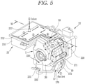
FIG. 5 is a conceptual view illustrating a movement path of cooling water inFIG. 1 . -
FIG. 6 is a conceptual view illustrating inflow and outflow paths of cooling water in the inverter housing ofFIG. 5 . -
FIG. 7 is a cross-sectional view illustrating a path through which cooling water moves from the inverter housing to the motor housing inFIG. 5 . -
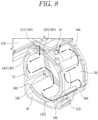
FIG. 8 is a conceptual view illustrating a path in which the cooling water moves in a zigzag form along a cooling water flow path inside the motor housing inFIG. 5 . -
FIG. 9 is an exploded view illustrating a cooling water flow path ofFIG. 8 deployed on a plane, which illustrates a movement path of the cooling water. -
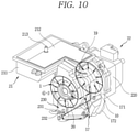
FIG. 10 is a conceptual view illustrating a movement path of oil inFIG. 1 . -
FIG. 11 is a conceptual view illustrating a state in which oil is sprayed through injection holes in all sections along a circumferential direction of the motor housing inFIG. 9 and an oil flow path forming part formed in a gearbox housing. -
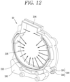
FIG. 12 is a conceptual view illustrating a path through which oil is sprayed in all sections along a circumferential direction of a housing for oil injection ofFIG. 2 . -
FIG. 13 is an enlarged conceptual view of a part "XIII" inFIG. 4 , which illustrates a path through which oil is diverged from a heat exchanger into the motor housing. - Description will now be given in detail according to exemplary implementations disclosed herein, with reference to the accompanying drawings. For the sake of brief description with reference to the drawings, the same or equivalent components may be provided with the same or similar reference numbers, and description thereof will not be repeated. In general, a suffix such as "module" and "unit" may be used to refer to elements or components. Use of such a suffix herein is merely intended to facilitate description of the specification, and the suffix itself is not intended to give any special meaning or function. In describing the present disclosure, if a detailed explanation for a related known function or construction is considered to unnecessarily divert the gist of the present disclosure, such explanation has been omitted but would be understood by those skilled in the art. The accompanying drawings are used to help easily understand the technical idea of the present disclosure and it should be understood that the idea of the present disclosure is not limited by the accompanying drawings. The idea of the present disclosure should be construed to extend to any alterations, equivalents and substitutes besides the accompanying drawings.
- It will be understood that although the terms first, second, etc. may be used herein to describe various elements, these elements should not be limited by these terms. These terms are generally only used to distinguish one element from another.
- It will be understood that when an element is referred to as being "connected with" another element, the element can be connected with the another element or intervening elements may also be present. In contrast, when an element is referred to as being "directly connected with" another element, there are no intervening elements present.
- A singular representation may include a plural representation unless it represents a definitely different meaning from the context.
- Terms such as "include" or "has" are used herein and should be understood that they are intended to indicate an existence of several components, functions or steps, disclosed in the specification, and it is also understood that greater or fewer components, functions, or steps may likewise be utilized.
-
FIG. 1 is a perspective view of an intelligent power generation module (IPGM) in accordance with the present disclosure,FIG. 2 is an exploded view ofFIG. 1 ,FIG. 3 is a perspective view illustrating a state in which anIGBT 216, acapacitor 215, andbus bars 217 are mounted inside aninverter 21 after aninverter cover 212 and acooling plate 214 are removed inFIG. 1 , andFIG. 4 is a perspective view illustrating a direction in which an assembly of astator 24 and arotor 25 is mounted to amotor housing 10 and a direction in which internal parts of theinverter 21 are mounted to aninverter housing 210 inFIG. 2 . -
FIG. 5 is a conceptual view illustrating a movement path of cooling water inFIG. 1 ,FIG. 6 is a conceptual view illustrating inflow and outflow paths of cooling water in theinverter housing 210 ofFIG. 5 ,FIG. 7 is a cross-sectional view illustrating a path through which cooling water moves from theinverter housing 210 to themotor housing 10 inFIG. 5 ,FIG. 8 is a conceptual view illustrating a path in which the cooling water moves in a zigzag form along a coolingwater flow path 11 inside themotor housing 10 inFIG. 5 , andFIG. 9 is an exploded view illustrating a coolingwater flow path 11 ofFIG. 8 deployed on a plane, which illustrates a movement path of the cooling water. - An intelligent power generation module (IPGM) according to the present disclosure may include an
electric motor 1, aninverter 21, and agearbox 22. - The
electric motor 1 may generate power by including astator 24 and arotor 25. - The
stator 24 and therotor 25 may be received inside amotor housing 10. Themotor housing 10 may be formed in a cylindrical shape. An accommodation space for accommodating thestator 24 and therotor 25 may be defined in themotor housing 10. Anoil sump 16 may be defined at a lower surface of themotor housing 10. Theoil sump 16 may communicate with the accommodation space of themotor housing 10 and may temporarily store oil. - The
stator 24 may include astator core 240 and astator coil 242. Thestator coil 242 may be wound around slots that are spaced apart from one another in a circumferential direction of thestator core 240. Parts of thestator coil 242 may protrude axially to both ends of thestator core 240 oriented in a lengthwise (longitudinal) direction of thestator core 240. The parts of thestator coil 242 protruding to the both ends of thestator core 240 may be referred to as end turns. - The
stator coil 242 may be configured as a three-phase (U, W, and V-phase) coil and may be connected to a three-phase AC power source. A connection ring that includes abusbar 217 for connecting a power connecting portion for applying power to the three-phase coils of thestator coil 242 to neutral lines disposed on ends of the three-phase coils may be mounted to thestator coil 242. - The power connecting portion may include three-phase terminals. The power connecting portion may be integrally formed with the connection ring.
- The
rotor 25 may be rotatably disposed in thestator core 240 with an air gap therebetween. Therotor 25 may include a rotor core and permanent magnets (not shown). A rotatingshaft 26 may be coupled into the rotor core to be rotatable together with the rotor core. - Both end portions of the
rotating shaft 26 may be rotatably supported by bearings. - A resolver may be disposed on one side of the
rotating shaft 26 in a longitudinal direction of therotating shaft 26. - Another side of the
rotating shaft 26 may be connected to a driving shaft of thegearbox 22. - The
gearbox 22 may include agearbox housing 220 and gears provided inside thegearbox housing 220. The gears may be configured to reduce the number of turns occurred in therotating shaft 26 of theelectric motor 1 and increase a torque. The gears may be configured as a planetary gear set. The planetary gear set may include a ring gear, a sun gear, a planetary gear, a carrier, and the like. - The
motor housing 10 may be formed in a cylindrical shape, and both sides of themotor housing 10 in the longitudinal direction may be open. - A
housing 19 for oil injection (hereinafter, referred to as an oil injection housing 19) and ashield cover 20 may be coupled to one open end portion of themotor housing 10. - Another end portion of the
motor housing 10 may be covered by thegearbox housing 220. A plurality of coupling portions may be formed on the one end portion of themotor housing 10 to be coupled to thegearbox housing 220. - The
inverter 21 may include acapacitor 215 and anIGBT 216 to operate theelectric motor 1. - An
inverter housing 210 may be formed in a rectangular shape extending along the longitudinal direction of themotor housing 10. A connectingportion 211 may extend from one side surface of theinverter housing 210 to cover a top portion of themotor housing 10. - The connecting
portion 211 may be integrally formed on a circumferential surface of themotor housing 10. Theinverter housing 210 may extend in a tangential direction with respect to the circumferential surface of themotor housing 10. - The
motor housing 10 and theinverter housing 210 may be integrally formed with each other, so that theelectric motor 1 and theinverter 21 can be integrated. When theinverter 21 and the electric motor are configured as a single housing, a manufacturing cost can be reduced and strength can be improved. - An upper portion of the
inverter housing 210 may be open, and aninverter cover 212 may be detachably coupled to the upper opening of theinverter housing 210. - A
cooling plate 214 may be mounted on an upper portion of theinverter housing 210. Thecooling plate 214 may have a shape corresponding to the shape of theinverter housing 210. Theinverter cover 212 may be mounted on an upper portion of thecooling plate 214 to cover a part or all of thecooling plate 214. - An inverter assembly such as the
capacitor 215 and theIGBT 216 may be accommodated inside theinverter housing 210. - The
capacitor 215, theIGBT 216, and the plurality ofbus bars 217 may be accommodated inside theinverter housing 210 while being suspended upside down from a lower surface of thecooling plate 214. - With this configuration, heat generated from each of the
capacitor 215, theIGBT 216, and the plurality ofbus bars 217 can be efficiently cooled by thecooling plate 214 due to a temperature difference between an upper end portion of each of thecapacitor 215, theIGBT 216, and the plurality ofbus bars 217 and thecooling plate 214. - The
capacitor 215, theIGBT 216, and the plurality ofbus bars 217 may be disposed in the order of being farthest apart from the uppermost end of themotor housing 10 in the tangential direction. The three-phase terminal of the power connecting portion of theelectric motor 1 may be disposed at the uppermost end of themotor housing 10. - The
shield cover 20 may cover the three-phase terminal of the power connecting portion. - A cooling water flow path may be defined at an inner side of the
cooling plate 214. A cooling water flowpath forming groove 2141 may be formed in an inner side of thecooling plate 214. The cooling water flowpath forming groove 2141 may be formed over an entire area of thecooling plate 214 and may have a shallow depth. - The cooling water flow
path forming groove 2141 having this structure can allow even a small amount of cooling water to come in contact with thecapacitor 215 and theIGBT 216 in an area as wide as possible, thereby improving cooling performance of the cooling water. - A heat absorbing surface may be formed on one side surface of the
IGBT 216. The heat absorbing surface may come in contact with thecooling plate 214 or directly with the cooling water. In the implementation, anopening 2142 may be formed through a lower surface of thecooling plate 214 such that theIGBT 216 can come in direct contact with cooling water. Accordingly, the cooling water and the heat absorbing surface can come in contact with each other through theopening 2142. Theopening 2142 and the heat absorbing surface may have the same shape and size. In this case, a sealing member may be disposed between the coolingplate 214 and the heat absorbing surface to prevent leakage of the cooling water from thecooling plate 214 to the inner space of theinverter housing 210. - With this configuration, the cooling water can directly absorb heat from the
IGBT 216 through the heat absorbing surface so as to improve cooling performance. - The plurality of
bus bars 217 may be disposed close to the three-phase terminal of the power connector of theelectric motor 1. One side of each of the plurality ofbus bars 217 may be connected to thecapacitor 215 and theIGBT 216, and another side of each of the plurality ofbus bars 217 may be connected to the three-phase terminal of the power connector. Accordingly, theinverter 21 can operate theelectric motor 1. - With this configuration, a connection length of the bus bars 217 can be reduced and thus heat dissipation of the bus bars 217 can be reduced. Therefore, more heat can be cooled by the same amount of cooling water, result in improving cooling performance.
- A cooling
water inlet port 213 may be disposed on one side of theinverter cover 212. - One side of the cooling
water inlet port 213 may be connected to communicate with the cooling water flow path of thecooling plate 214 and another side of the coolingwater inlet port 213 may be connected to a radiator disposed in the front of the vehicle, so that the cooling water cooled down by the radiator can be introduced into the cooling water flow path inside theinverter housing 210 through the coolingwater inlet port 213. - A cooling
water communication port 2143 may be formed through a lower surface of one side of thecooling plate 214. - One side of the cooling
water communication port 2143 may be connected to communicate with the cooling water flow path and another side of the coolingwater communication port 2143 may be connected to communicate with the cooling water flow path inside themotor housing 10. - The cooling
water inlet port 213 may be disposed adjacent to thecapacitor 215 and the coolingwater communication port 2143 may be disposed adjacent to the plurality of bus bars 217. - The cooling water introduced through the cooling
water inlet port 213 may sequentially cool down thecapacitor 215, theIGBT 216, and the plurality ofbus bars 217, and then flow into themotor housing 10 through the coolingwater communication port 2143. - The
motor housing 10 may be formed in a cylindrical shape with both sides open along the longitudinal direction. - The
stator 24, therotor 25, and the like may be accommodated in themotor housing 10 through one opening of themotor housing 10. - The
stator core 240 may be formed in a cylindrical shape, and a plurality ofear parts 241 may protrude radially from an outer circumferential surface of thestator core 240. The plurality ofear parts 241 may extend along the longitudinal direction of thestator core 240. The plurality ofear parts 241 may be spaced apart from one another in a circumferential direction of thestator core 240. - Each of the plurality of
ear parts 241 may have a bolt coupling hole therein. A plurality of bolts extending in the longitudinal direction of thestator core 240 may be inserted through the bolt coupling holes of therespective ear parts 241, such that thestator core 240 can be coupled to themotor housing 10. - A
gearbox housing 220 may cover the rear end portion of themotor housing 10. A plurality of coupling portions that are spaced apart from one another in the circumferential direction may be formed on each of the front end portion of thegearbox housing 220 and the rear end portion of themotor housing 10. Coupling members such as bolts may be inserted through the coupling portions such that thegearbox housing 220 and themotor housing 10 can be coupled to each other. - The
motor housing 10 may include a plurality of earpart accommodating portions 140. The plurality of earpart accommodating portions 140 may extend along the longitudinal direction of themotor housing 10 and protrude outward in the radial direction of themotor housing 10. The earpart accommodating portions 140 may surround theear parts 241, respectively. - The plurality of
ear parts 241 and the plurality of earpart accommodating portions 140 may be disposed on a left upper portion, a left lower portion, a right upper portion, and a right lower portion of themotor housing 10, respectively, at about intervals of 90 degrees when themotor housing 10 is viewed from the front in a direction in which thestator core 240 is inserted. - The
ear part 241 may be formed in a semicircular shape, and upper two earpart accommodating portions 140 among the plurality of earpart accommodating portions 140 may be formed in a semicircular shape with a diameter larger than that of theear part 241. Lower two earpart accommodating portions 140 among the plurality of earpart accommodating portions 140 may communicate with an upper portion of theoil sump 16. - The ear
part accommodating portions 140 may be open toward the front in the longitudinal direction of themotor housing 10, such that theear parts 241 can be inserted into the front openings of the earpart accommodating portions 140. - The stator and rotor assembly may be mounted by being inserted in the longitudinal direction of the
motor housing 10. In this case, theear parts 241 may be slidably coupled along the earpart accommodating portions 140. As theear parts 241 and the earpart accommodating portions 140 are coupled to each other, the stator and rotor assembly may be allowed to be slidable in the longitudinal direction of themotor housing 10 but prevented from moving in the circumferential direction. - Coupling
grooves 145 may be formed in rear end portions of the earpart accommodating portions 140 and bolts passing through theear parts 241 may be coupled to thecoupling grooves 145, so that thestator core 240 can be coupled to themotor housing 10. - The ear
part accommodating portions 140 may be formed to have a cross-sectional area that increases from the rear to the front in the longitudinal direction, which may facilitate a mold to be smoothly released during molding by die casting. - The
motor housing 10 may have a double wall. A coolingwater flow path 11 may be defined between an outer wall and an inner wall in a radial direction of the double wall. The coolingwater flow path 11 may include a plurality of heat-exchange cells 110, a plurality ofpartition walls 120, and a plurality of communication holes 130. The plurality ofcommunication holes 110 may be disposed in themotor housing 10 to be spaced apart from one another in the circumferential direction. - Each of the plurality of heat-
exchange cells 110 may extend in the longitudinal direction of themotor housing 10. Two heat-exchange cells 110 may be disposed between the two earpart accommodating portions 140 adjacent to each other in the circumferential direction. - The plurality of heat-
exchange cells 110 may be defined by the plurality ofpartition walls 120 in the circumferential direction. Each of the plurality ofpartition walls 120 may extend in the longitudinal direction of themotor housing 10. The plurality ofpartition walls 120 may be spaced apart from one another in the circumferential direction. - Each of the plurality of
partition walls 120 may protrude in the radial direction, such that an outer end is connected to the outer wall of themotor housing 10 and an inner end is connected to the inner wall of themotor housing 10. - The plurality of
communication holes 130 may be alternately formed at front end portions of the plurality ofpartition walls 120 in the circumferential direction, such that two heat-exchange cells 110 adjacent to each other in the circumferential direction can communicate with each other. - The plurality of heat-
exchange cells 110 may include a first heat-exchange cell 111 to an Nth heat-exchange cell 110. In this implementation, eight heat-exchange cells 110 may be provided. - Among the plurality of heat-
exchange cells 110, the heat-exchange cell 110 communicating with the coolingwater communication port 2143 may be referred to as a first heat-exchange cell 111. - Among the plurality of heat-
exchange cells 110, the heat-exchange cell 110 communicating with a coolingwater outlet port 15 may be referred to as an eighth heat-exchange cell 118. - The first heat-
exchange cell 111 and the eighth heat-exchange cell 118 may be disposed adjacent to each other in the circumferential direction. A partition wall disposed at the uppermost end of themotor housing 10 among the plurality ofpartition walls 120 may be referred to as afirst partition wall 121. - The
first partition wall 121 may be disposed between the first heat-exchange cell 111 and the eighth heat-exchange cell 118 to partition the first heat-exchange cell 111 and the eighth heat-exchange cell 118 from each other. Thecommunication hole 130 may not be formed at the front or rear end portion of thefirst partition wall 121. If thecommunication hole 130 is provided at thefirst partition wall 121, cooling water may move from the first heat-exchange cell 111 directly to the eighth heat-exchange cell 118 through thecommunication hole 130, to thereby being discharged through the coolingwater outlet port 15 almost without heat exchange. - The second heat-
exchange cell 112 may be spaced apart from the first heat-exchange cell 111 in a counterclockwise direction when viewed from the front of themotor housing 10. The first earpart accommodating portion 141 located at the left upper portion may be disposed between the first heat-exchange cell 111 and the second heat-exchange cell 112. - The third heat-
exchange cell 113 may be spaced apart from the second heat-exchange cell 112 in the counterclockwise direction, and thecommunication hole 130 may be formed at the front end portion of thesecond partition wall 122 by which the second heat-exchange cell 112 and the third heat-exchange cell 113 are partitioned from each other. - The fourth heat-
exchange cell 114 may be spaced apart from the third heat-exchange cell 113 in the counterclockwise direction with interposing the second earpart accommodating portion 142 located at the left lower portion therebetween. - The fifth heat-
exchange cell 115 may be spaced apart from the fourth heat-exchange cell 114 in the counterclockwise direction, and thecommunication hole 130 may be formed at the front end portion of thethird partition wall 123 by which the fourth heat-exchange cell 114 and the fifth heat-exchange cell 115 are partitioned from each other. - The
oil sump 16 may be disposed in a lower portion of themotor housing 10. Theoil sump 16 may be formed in a rectangular or trapezoidal shape. - The
oil sump 16 may communicate with a circular inner space of themotor housing 10. Accordingly, oil sprayed into the inner space of themotor housing 10 may be temporarily stored in a lower portion of theoil sump 16. Theoil sump 16 and the circular inner space may be partitioned by the fourth and fifth heat-exchange cells exchange cells 110. - A
support rib 1151 may extend on a lower surface of the fourth heat-exchange cell 114 or the fifth heat-exchange cell 115 in the longitudinal direction of themotor housing 10, to support the fourth heat-exchange cell 114 and the fifth heat-exchange cell 115. An upper end portion of thesupport rib 1151 may be connected to the lower surface of the fourth heat-exchange cell 114 or the fifth heat-exchange cell 115, and a lower end portion of thesupport rib 1151 may be connected to a bottom surface of theoil sump 16. - The sixth heat-
exchange cell 116 may be spaced apart from the fifth heat-exchange cell 115 in the counterclockwise direction with interposing the third earpart accommodating portion 143 therebetween. The sixth heat-exchange cell 116 may be formed in a right surface of themotor housing 10 to face the third heat-exchange cell 113. - The seventh heat-
exchange cell 117 may be spaced apart from the sixth heat-exchange cell 116 in the counterclockwise direction. Thefourth partition wall 124 may partition the sixth heat-exchange cell 116 and the seventh heat-exchange cell 117 from each other, and thecommunication hole 130 may be formed at the front end portion of thefourth partition wall 124. - The eighth heat-
exchange cell 118 may be spaced apart from the seventh heat-exchange cell 117 in the counterclockwise direction with interposing the fourth earpart accommodating portion 144 located at the right upper portion therebetween. - The communication holes 130 may be formed at the rear of the
coupling grooves 145 of the first to fourth earpart accommodating portions 141 to 144, respectively. Thecommunication hole 130 formed at the rear of the first earpart accommodating portion 141 may allow the first heat-exchange cell 111 and the second heat-exchange cell 112 to communicate with each other in the circumferential direction. - The
communication hole 130 formed at the rear of the second earpart accommodating portion 142 may allow the third heat-exchange cell 113 and the fourth heat-exchange cell 114 to communicate with each other in the circumferential direction. - The
communication hole 130 formed at the rear of the third earpart accommodating portion 143 may allow the fifth heat-exchange cell 115 and the sixth heat-exchange cell 116 to communicate with each other in the circumferential direction. - The
communication hole 130 formed at the rear of the fourth earpart accommodating portion 144 may allow the seventh heat-exchange cell 117 and the eighth heat-exchange cell 118 to communicate with each other in the circumferential direction. - The cooling
water outlet port 15 may be formed at the upper portion of themotor housing 10. A lower end portion of the coolingwater outlet port 15 may communicate with the eighth heat-exchange cell 118, and an upper end portion of the coolingwater outlet port 15 may communicate with the outside. - A
heat exchanger 17 may be installed on one side of an outer surface of themotor housing 10. Theheat exchanger 17 may be provided to allow heat exchange between oil and cooling water. A part of theheat exchanger 17 may overlap an outer surface of the sixth heat-exchange cell 116 in the radial direction and another part of theheat exchanger 17 may overlap one side surface of theoil sump 16 in a thickness direction. - The
heat exchanger 17 may be provided with a coolingwater suction port 170. The coolingwater outlet port 15 of themotor housing 10 may be connected to the coolingwater suction port 170 of theheat exchanger 17. One side of a coolingwater connection pipe 171 may be connected to the coolingwater outlet port 15 and another side of the coolingwater connection pipe 171 may be connected to the coolingwater suction port 170 of theheat exchanger 17. - The cooling
water flow path 11 may be defined in theheat exchanger 17. The coolingwater suction port 170 may be connected to the coolingwater flow path 11, and a coolingwater discharge port 172 may be provided at theheat exchanger 17 to communicate with the coolingwater flow path 11. - The cooling
water discharge port 172 may be connected to a radiator disposed in the front of the vehicle by a cooling water circulation line. - With this configuration, the cooling water may first be cooled in the radiator and then flow into the cooling
water inlet port 213 formed through theinverter cover 212. The cooling water can sequentially cool down thecapacitor 215, theIGBT 216, and the bus bars 217 accommodated in theinverter housing 210 while moving along the coolingwater flow path 11 defined in thecooling plate 214. - Subsequently, the cooling water may move from the
inverter housing 210 into themotor housing 10 through the coolingwater communication port 2143. The coolingwater communication port 2143 may communicate with the first heat-exchange cell 111 of themotor housing 10, such that the cooling water can move into the first heat-exchange cell 111. - The cooling water may then sequentially flow along the first to eighth heat-
exchange cells 111 to 118 in the circumferential direction (counterclockwise), thereby cooling down theelectric motor 1. - Afterwards, the cooling water flowing out through the cooling
water outlet port 15 of the eighth heat-exchange cell 118 may move into theheat exchanger 17 through the coolingwater connection pipe 171 so as to exchange heat with oil, thereby cooling down the oil. - The heat-exchanged cooling water may move to the radiator through the cooling
water discharge port 172 of theheat exchanger 17 and emit heat to air in the radiator, and then circulate back to the coolingwater inlet port 213 of theinverter cover 212, thereby cooling down theinverter 21. A water pump of the vehicle may supply circulating power to the cooling water so as to transfer the cooling water discharged through the coolingwater discharge port 172 to the radiator and circulate the cooling water from the radiator back to the coolingwater inlet port 213. -
FIG. 10 is a conceptual view illustrating a movement path of oil inFIG. 1 ,FIG. 11 is a conceptual view illustrating a state in which oil is sprayed through injection holes in all sections along a circumferential direction of themotor housing 10 inFIG. 9 and a second oil flow path forming part formed in thegearbox housing 220,FIG. 12 is a conceptual view illustrating a path through which oil is sprayed in all sections along a circumferential direction of anoil injection housing 19 ofFIG. 2 , andFIG. 13 is an enlarged conceptual view of a part "XIII" inFIG. 4 , which illustrates a path through which oil is diverged from theheat exchanger 17 into themotor housing 10. - An
oil flow path 180 along which oil flows may be defined inside each of themotor housing 10 and thegearbox housing 220. Theoil flow path 180 may include a first oil flowpath forming part 181 and a second oil flowpath forming part 182 provided in themotor housing 10 to face each other in the longitudinal direction. - The first oil flow
path forming part 181 may extend from the rear end portion of themotor housing 10 in the circumferential direction, and may be open to the rear of themotor housing 10. - The first oil flow
path forming part 181 may extend in the longitudinal direction of themotor housing 10. The first oil flowpath forming part 181 may be defined at an inner side of themotor housing 10. - The first oil flow
path forming part 181 may be configured as a double wall. The first oil flowpath forming part 181 may share the rear end portion of the inner wall of themotor housing 10 as its outer wall. An inner wall of the first oil flowpath forming part 181 may be spaced apart radially inward from the rear end portion of the inner wall of themotor housing 10. - The second oil flow
path forming part 182 may extend concavely in an inner surface of thegearbox housing 220 along the circumferential direction. The second oil flowpath forming part 182 may be configured as a double wall. The double wall of the second oil flowpath forming part 182 may be disposed to face the double wall of the first oil flowpath forming part 181 in the longitudinal direction to define a singleoil flow path 180. The singleoil flow path 180 may be defined along the circumferential direction. - A plurality of
first injection nozzles 183 may be radially formed through the inner wall of the first oil flowpath forming part 181. The plurality offirst injection nozzles 183 may be spaced apart from one another in the circumferential direction of the first oil flowpath forming part 181. - An
oil suction part 221 may be formed on one side of thegearbox housing 220. Theoil suction part 221 may include a firstoil suction portion 2211 extending from the rear of themotor housing 10 toward thegearbox housing 220 in the axial direction, and a secondoil suction portion 2212 extending from the firstoil suction portion 2211 in the radial direction. - Oil introduced into the
oil flow path 180 through theoil suction part 221 may be diverged in half (1/2) into opposite directions at one point of theoil flow path 180, so as to be distributed into the plurality offirst injection nozzles 183 while rotating from the one point to an opposite point spaced apart by 180 degrees, thereby being sprayed into the inner space of themotor housing 10 in the radial direction. - The oil may be directly sprayed onto the end turn of the
stator coil 242 protruding axially from the rear end portion in the longitudinal direction of thestator core 240, to absorb heat generated in thestator coil 242. - The oil diverged to rotate in the opposite directions may join at the opposite point.
- An
oil pump 230 may be mounted on a lower portion of a front surface of ahousing 19 for oil injection (i.e., oil injection housing 19). Apump inlet 231 may be disposed at one side of theoil pump 230. Theoil inlet 231 may communicate with a bottom surface of theoil sump 16 through an oil suction pipe. - The
oil pump 230 may pump up oil from theoil sump 16. - A
pump outlet 232 may be disposed at another side of theoil pump 230. Thepump outlet 232 may communicate with an oil suction port disposed at one side of theheat exchanger 17 through an oil discharge pipe. The pumped oil may flow into theheat exchanger 17. - An oil
distribution flow path 184 may extend along the longitudinal direction of themotor housing 10. A front end portion of the oildistribution flow path 184 in the longitudinal direction may communicate with theoil suction part 221 of theoil injection housing 19 and a rear end portion of the oildistribution flow path 184 in the longitudinal direction may communicate with theoil suction part 221 of thegearbox housing 220. - An
oil discharge port 173 may be disposed in theheat exchanger 17. Theoil discharge port 173 may communicate with a middle portion of the oildistribution flow path 184. - The
heat exchanger 17 may include theoil flow path 180 and the coolingwater flow path 11 to allow the heat exchange between oil and cooling water. - Oil may be sucked into the
heat exchanger 17, cooled by heat exchange with cooling water, and then divergently flow from the oildistribution flow path 184 toward the front end portion and the rear end portion in the longitudinal direction through theoil discharge port 173. - The oil may be introduced from the rear end portion of the oil
distribution flow path 184 into the second oil flowpath forming part 182 through theoil suction part 221 of thegearbox housing 220. The oil may then be diverged in half from the suction point of the second oil flowpath forming part 182 toward opposite directions so as to be distributed into the plurality offirst injection nozzles 183 while rotating along the circumferential direction. The oil may thus be sprayed onto thestator coil 242 through the plurality offirst injection nozzles 183. Accordingly, theelectric motor 1 can be cooled simultaneously by oil and cooling water. - The
oil injection housing 19 may be coupled to the front end portion of themotor housing 10. Theoil injection housing 19 may include anoil manifold 193, a powerconnector cover portion 194, and an oilsump cover portion 195. - The
oil manifold 193 may protrude with a small diameter from one side surface of theoil injection housing 19 in the longitudinal direction of themotor housing 10 and extend in the circumferential direction. Theoil manifold 193 may have a double-wall structure. - An outer wall and an inner wall of the
oil manifold 193 may be radially spaced apart from each other to define theoil flow path 180 such that oil can flow between the outer wall and the inner wall. A plurality ofsecond injection nozzles 196 may be radially formed through the inner wall of theoil manifold 193. - The plurality of
second injection nozzles 196 may be spaced apart from one another in the circumferential direction, to spray oil in all sections of 360 degrees in the circumferential direction. - The
oil injection housing 19 may cover the coolingwater flow path 11 of themotor housing 10. - The power
connector cover portion 194 may protrude upward from an upper portion of theoil injection housing 19 to surround the power connector. - The oil
sump cover portion 195 may protrude downward from a lower portion of theoil injection housing 19, to cover a front opening of theoil sump 16. - The
shield cover 20 may be coupled to cover the powerconnector cover portion 194 and theoil manifold 183 of theoil injection housing 19. - An
oil suction part 190 may extend radially from one side of theoil injection housing 19. One side of theoil suction part 190 may communicate with theoil manifold 193 and another side of theoil suction part 190 may be connected to theoil pump 230. - The
oil suction part 190 may include a firstoil suction portion 191 extending in the axial direction and a secondoil suction portion 192 extending in a radial direction. The secondoil suction portion 192 may be connected to themanifold 193. - Oil introduced into the
oil manifold 193 through theoil suction part 190 may be diverged in half into opposite directions at one point of theoil manifold 193 in the circumferential direction. The diverged oil can thus move from the one point to another point opposite to the one point by 180 degrees along the opposite directions. - The two oil flows made in the opposite directions may join at the opposite one point. Therefore, the oil can be sprayed in the radial direction into the inner space of the
motor housing 10 at all sections of 360 degrees through the plurality ofsecond injection nozzles 196. - The oil may be directly sprayed onto the end turn of the
stator coil 242 protruding axially from the front end portion in the longitudinal direction of thestator core 240, to absorb heat generated in thestator coil 242. - The oil may be introduced from the front end portion of the oil
distribution flow path 184 into theoil manifold 193 through theoil suction part 190 of theoil injection housing 19. The oil may then be diverged in half at the suction point of the manifold 193 toward opposite directions so as to be distributed into the plurality offirst injection nozzles 196 while rotating along the circumferential direction. The oil may thus be sprayed onto thestator coil 242 through the plurality ofsecond injection nozzles 196. Accordingly, theelectric motor 1 can be cooled simultaneously by oil and cooling water. - A first gasket may be disposed between the
shield cover 20 and theoil injection housing 19 to seal a gap between theshield cover 20 and theoil injection housing 19. A second gasket may be disposed between theoil injection housing 19 and themotor housing 10 to seal a gap between theoil injection housing 19 and themotor housing 10. Also, a third gasket may be disposed between themotor housing 10 and thegearbox housing 220 to seal a gap between themotor housing 10 and thegearbox housing 220. - Therefore, according to the present disclosure, an electric motor can be cooled down simultaneously by cooling water flowing along the cooling
water flow path 11 extending in the axial direction and oil flowing along theoil flow path 180 extending in the circumferential direction inside themotor housing 10, thereby improving cooling performance and motor output of the electric motor. - In addition, the plurality of
first injection nozzles 183 may be disposed in a spaced manner along the circumferential direction in all sections of 360 degrees at the first oil flowpath forming part 181, which is formed in the circumferential direction at the inner side of the rear end portion of themotor housing 10 in the longitudinal direction, and the plurality ofsecond injection nozzles 196 may be disposed in a spaced manner along the circumferential direction at theoil manifold 193, which is formed in the circumferential direction inside theoil injection housing 19 mounted to the front end portion of themotor housing 10 in the longitudinal direction. Accordingly, oil can be sprayed directly onto the end turn of thestator coil 242 in all the sections of 360 degrees through the plurality offirst injection nozzles 183 andsecond injection nozzles 196, thereby enhancing heat dissipation performance of thestator coil 242. - As oil is sprayed in all the sections of 360 degrees, the cooling performance of the oil can be uniformly maintained in the circumferential direction of the
stator coil 242 even when an electronic vehicle turns, travels uphill or downhill, or is accelerated/decelerated, and an occurrence of a dead zone of oil cooling in which thestator coil 242 is not wetted by the oil can be prevented. - Further, the
cooling flow path 11 of themotor housing 10 may be configured as an axial flow path extending in the axial direction so as to be manufactured by die casting, and themotor housing 10 may not have to be formed by gravity casting that is employed to form a spiral flow path in the related art, thereby improving productivity. - Moreover, the
electric motor 1 can employ a structure for cooling only using cooling water without an oil cooling structure, if necessary. For example, a low-cost product can be configured to have a cooling structure only using cooling water without theoil pump 230 and theheat exchanger 17. - In addition, a high output
electric motor 1 can employ a cooling structure simultaneously using both oil and cooling water so as to continuously maintain a high output compared to a maximum output (60% of the maximum output). - In addition, the
inverter 21 and the electric motor can be configured by a single integrated housing, thereby reducing a manufacturing cost and improving strength. - The cooling
water flow path 11 can extend in the axial direction and have a zigzag shape along the circumferential direction. Therefore, the structure of the coolingwater flow path 11 along which the cooling water can circulate while avoiding positions of bolting holes can be achieved even when thestator 24 is not press-fitted into themotor housing 10 but is coupled to themotor housing 10 by bolts in a type in whichear parts 241 are formed at four places of thestator core 240. - The
capacitor 215, theIGBT 216, and the bus bars 217 of theinverter 21 can be suspended compactly upside down from the lower surface of thecooling plate 214, so as to be cooled simultaneously by cooling water, thereby improving cooling performance of theinverter 21. Those electric components such as thecapacitor 215 of theinverter 21 can be mounted upside down so as to reduce the length of the bus bars 217 for connection with the three-phase AC power source of theelectric motor 1, which may result in reducing an amount of heat generated in the bus bars 217 and increasing cooling efficiency accordingly. - Cooling water can indirectly cool down the
inverter 21 and the electric motor while moving along inner flow paths of theinverter housing 210 and themotor housing 10 and then absorb heat through heat exchange with oil in theheat exchanger 17, thereby enhancing heat dissipation performance. - Oil can be sprayed through the plurality of injection nozzles formed in the
motor housing 10 at all sections of 360 degrees in the circumferential direction, a guide ring for oil dropping may not additionally be needed to thereby reduce the number of components and assembly processes, resulting in reducing a manufacturing cost.
Claims (15)
- An intelligent power generation module comprising:an electric motor including a motor housing in which a stator and a rotor are accommodated;an inverter including an inverter housing in which a capacitor, an IGBT, and bus bars are accommodated;a cooling water flow path defined in the motor housing such that the cooling water flows therein;a first oil flow path extending in one end portion of the motor housing in a longitudinal direction of the motor housing along a circumferential direction such that oil flows;a plurality of first injection nozzles disposed to be spaced apart from one another in the circumferential direction of the first oil flow path to spray the oil into an inner space of the motor housing;an oil injection housing mounted on another end portion of the motor housing in the longitudinal direction of the motor housing;a second oil flow path defined in the oil injection housing along the circumferential direction such that oil flows; anda plurality of second injection nozzles disposed to be spaced apart from one another in the circumferential direction of the second oil flow path to spray the oil into the inner space of the motor housing.
- The intelligent power generation module of claim 1, wherein the motor housing has a dual-wall structure having an outer wall and an inner wall spaced apart in a radial direction, and comprises a first oil flow path forming part defining the first oil flow path between the outer wall and the inner wall, and
wherein the plurality of first injection nozzles extend in all sections of 360 degrees in the radial direction. - The intelligent power generation module of claim 2, further comprising a gearbox having a gearbox housing for accommodating gears therein, and configured to decelerate speed of the electric motor.
- The intelligent power generation module of claim 3, wherein the gearbox housing comprises a second oil flow path forming part disposed to face the first oil flow path forming part to define the first oil flow path along with the first oil flow path forming part.
- The intelligent power generation module of claim 1, wherein the oil injection housing comprises:an oil manifold having a dual-wall structure having an outer wall and an inner wall spaced apart in a radial direction, and defining the second oil flow path between the outer wall and the inner wall;a power connector cover portion protruding upward from an upper portion of the oil manifold to surround a power connector for applying power to the stator coil; andan oil sump cover portion protruding downward from a lower portion of the oil manifold to cover an oil sump disposed in a lower portion of the motor housing to temporarily store oil.
- The intelligent power generation module of claim 1, further comprising an oil pump mounted to a front side of the motor housing to transfer oil temporarily stored in a lower portion of the motor housing to the plurality of first injection nozzles and the plurality of second injection nozzles.
- The intelligent power generation module of claim 1, further comprising a heat exchanger installed on one side surface of the motor housing to exchange heat between the cooling water and the oil.
- The intelligent power generation module of claim 7, further comprising:an oil distribution flow path extending from an outer circumferential surface of the motor housing in the longitudinal direction to cross the heat exchanger in the longitudinal direction to distribute oil to the first oil flow path and the second oil flow path, respectively; andan oil discharge port disposed in the heat exchanger to communicate with the oil distribution flow path to discharge oil cooled by the heat exchanger to the oil distribution flow path.
- The intelligent power generation module of claim 1, wherein the motor housing and the inverter housing are integrally formed with each other, and the inverter housing extends from an upper end of an outer circumferential portion of the motor housing in a tangential direction.
- The intelligent power generation module of claim 9, wherein the inverter housing is open upward, and
wherein the inverter comprises:a cooling plate mounted to cover an open upper portion of the inverter housing and provided with a cooling water flow path forming groove on an upper surface thereof such that the cooling water flows to cool down the capacitor, the IGBT, and the bus bars; andan inverter cover mounted to cover an upper surface of the cooling plate. - The intelligent power generation module of claim 10, wherein the capacitor, the IGBT, and the bus bars are mounted while being suspended upside down from a lower surface of the cooling plate,wherein a power connector for applying three-phase power to the electric motor is mounted on an upper portion of the stator coil,wherein the bus bars are disposed close to the power connector in the tangential direction, andwherein the capacitor is disposed away from the power connector in the tangential direction, and the IGBT is disposed between the capacitor and the bus bars.
- The intelligent power generation module of claim 1, wherein the cooling water flow path comprises:a plurality of heat-exchange cells extending in the longitudinal direction of the motor housing and spaced apart from one another in the circumferential direction of the motor housing;a plurality of partition walls each disposed between adjacent heat-exchange cells of the plurality of heat-exchange cells to partition the plurality of heat-exchange cells; anda plurality of communication holes formed through the plurality of partition walls such that the plurality of heat-exchange cells communicate with one another in the circumferential direction.
- The intelligent power generation module of claim 12, wherein the stator comprises a plurality of ear parts protruding radially outward from an outer circumferential surface of a stator core to couple the stator and the motor housing to each other by a plurality of bolts, the plurality of ear parts accommodating the plurality of bolts therein,wherein the motor housing comprises a plurality of ear part accommodating portions protruding radially outward from an outer circumferential surface of the motor housing to accommodate the plurality of ear parts, respectively, andwherein the plurality of partition walls and the plurality of ear part accommodating portions are alternately disposed along the circumferential direction of the motor housing.
- The intelligent power generation module of claim 13, wherein the plurality of communication holes are disposed at front end portions of the partition walls or rear end portions of the ear part accommodating portions, respectively.
- The intelligent power generation module of claim 7, wherein a cooling water inlet port is formed through an inverter cover mounted to cover the inverter housing, such that the cooling water flows into the inverter housing through the cooling water inlet port, and
wherein a cooling water outlet port is formed through the heat exchanger, such that the cooling water heat-exchanged with the oil is discharged from the heat exchanger to outside through the cooling water outlet port.
Applications Claiming Priority (1)
| Application Number | Priority Date | Filing Date | Title |
|---|---|---|---|
| PCT/KR2019/003260 WO2020189826A1 (en) | 2019-03-20 | 2019-03-20 | Intelligent power generation module |
Publications (2)
| Publication Number | Publication Date |
|---|---|
| EP3944472A1 true EP3944472A1 (en) | 2022-01-26 |
| EP3944472A4 EP3944472A4 (en) | 2022-11-09 |
Family
ID=72520959
Family Applications (1)
| Application Number | Title | Priority Date | Filing Date |
|---|---|---|---|
| EP19920611.1A Pending EP3944472A4 (en) | 2019-03-20 | 2019-03-20 | Intelligent power generation module |
Country Status (4)
| Country | Link |
|---|---|
| US (1) | US11942833B2 (en) |
| EP (1) | EP3944472A4 (en) |
| CN (1) | CN113812070B (en) |
| WO (1) | WO2020189826A1 (en) |
Families Citing this family (8)
| Publication number | Priority date | Publication date | Assignee | Title |
|---|---|---|---|---|
| DE102021210319A1 (en) * | 2021-09-17 | 2023-03-23 | Robert Bosch Gesellschaft mit beschränkter Haftung | Seal arrangement in the cooling circuit of an e-axis module |
| US11950398B2 (en) | 2022-01-20 | 2024-04-02 | Borgwarner Luxembourg Automotive Systems Sa | Systems and methods for cooling electronic components of a vehicle |
| US11943903B2 (en) | 2022-01-20 | 2024-03-26 | Borgwarner Luxembourg Automotive Systems Sa | Systems and methods for cooling electronic components of a vehicle |
| US11785737B2 (en) * | 2022-01-20 | 2023-10-10 | Borg Warner Luxembourg Automotive Systems SA | Systems and methods for cooling electronic components of a vehicle |
| DE102022110820A1 (en) * | 2022-05-03 | 2023-11-09 | Bayerische Motoren Werke Aktiengesellschaft | Electric traction machine for a motor vehicle |
| CN114899979B (en) * | 2022-05-09 | 2023-07-25 | 浙江奥思伟尔电动科技有限公司 | Device for improving heat dissipation performance of motor winding |
| WO2024061450A1 (en) | 2022-09-20 | 2024-03-28 | Gkn Automotive Limited | Housing assembly and electric drive with such a housing assembly |
| FR3140493A1 (en) * | 2022-09-29 | 2024-04-05 | Nidec Psa Emotors | Set of rotating electric machine comprising an inverter |
Family Cites Families (23)
| Publication number | Priority date | Publication date | Assignee | Title |
|---|---|---|---|---|
| JP4167886B2 (en) * | 2002-11-25 | 2008-10-22 | 株式会社日本自動車部品総合研究所 | Rotating electric machine |
| JP2006166554A (en) * | 2004-12-06 | 2006-06-22 | Toyota Motor Corp | Rotating electric machine and manufacturing method of rotating electric machine |
| JP2007116807A (en) * | 2005-10-19 | 2007-05-10 | Komatsu Ltd | Vertical motor generator |
| WO2008085152A1 (en) * | 2006-12-29 | 2008-07-17 | Carrier Corporation | Oil cooled generator for trailer refrigeration unit |
| JP5099431B2 (en) * | 2008-02-15 | 2012-12-19 | アイシン・エィ・ダブリュ株式会社 | Inverter unit |
| JP5498773B2 (en) | 2009-12-24 | 2014-05-21 | 株式会社日本自動車部品総合研究所 | Rotating electric machine |
| DE102010008584A1 (en) * | 2010-02-19 | 2011-08-25 | Magna Powertrain Ag & Co Kg | Electric drive unit |
| JP2012105487A (en) * | 2010-11-11 | 2012-05-31 | Komatsu Ltd | Cooling device for electric motor |
| JP5706793B2 (en) * | 2011-09-20 | 2015-04-22 | 日立建機株式会社 | Generator motor and electric vehicle using the same |
| JP2013115903A (en) * | 2011-11-28 | 2013-06-10 | Hitachi Automotive Systems Ltd | Mechano-electric integration type electrically driven driving device |
| KR102068178B1 (en) * | 2012-12-03 | 2020-01-20 | 엘지전자 주식회사 | Electric Vehicle |
| CN105099084B (en) * | 2014-05-15 | 2017-10-17 | 中山大洋电机股份有限公司 | By the integrated dynamic system that traction electric machine and inverter are integrated |
| JP6442922B2 (en) * | 2014-08-22 | 2018-12-26 | 日本電産株式会社 | motor |
| JP6458436B2 (en) * | 2014-10-08 | 2019-01-30 | 三菱自動車工業株式会社 | Vehicle motor device |
| JP6543907B2 (en) * | 2014-10-08 | 2019-07-17 | 三菱自動車工業株式会社 | Motor device for vehicle |
| CN105932810B (en) * | 2015-02-27 | 2019-10-22 | 博泽沃尔兹堡汽车零部件有限公司 | Electric machine structure component |
| JP6552851B2 (en) * | 2015-03-19 | 2019-07-31 | 三菱重工サーマルシステムズ株式会社 | Compressor driving motor and cooling method thereof |
| US10411562B2 (en) * | 2016-01-14 | 2019-09-10 | Honeywell International Inc. | Compact high speed generator having passageways for air and cooling oil |
| KR102359705B1 (en) * | 2016-07-20 | 2022-02-08 | 엘지마그나 이파워트레인 주식회사 | Case for electric motor |
| JP6495215B2 (en) * | 2016-09-27 | 2019-04-03 | 本田技研工業株式会社 | Generator cooling structure for internal combustion engine |
| WO2018182117A1 (en) * | 2017-03-28 | 2018-10-04 | 엘지전자 주식회사 | Motor |
| US11011955B2 (en) * | 2017-03-28 | 2021-05-18 | Lg Electronics Inc. | Motor |
| DE102017211135A1 (en) * | 2017-06-30 | 2019-01-03 | Audi Ag | Electric machine and motor vehicle |
-
2019
- 2019-03-20 EP EP19920611.1A patent/EP3944472A4/en active Pending
- 2019-03-20 WO PCT/KR2019/003260 patent/WO2020189826A1/en unknown
- 2019-03-20 CN CN201980094401.9A patent/CN113812070B/en active Active
-
2021
- 2021-09-20 US US17/479,642 patent/US11942833B2/en active Active
Also Published As
| Publication number | Publication date |
|---|---|
| EP3944472A4 (en) | 2022-11-09 |
| WO2020189826A1 (en) | 2020-09-24 |
| CN113812070B (en) | 2024-01-05 |
| US20220006350A1 (en) | 2022-01-06 |
| CN113812070A (en) | 2021-12-17 |
| US11942833B2 (en) | 2024-03-26 |
Similar Documents
| Publication | Publication Date | Title |
|---|---|---|
| EP3944472A1 (en) | Intelligent power generation module | |
| EP1049234B1 (en) | Drive unit | |
| JP5261052B2 (en) | Rotating electric machine and rotating electric machine cooling system | |
| CN103931087B (en) | Electric rotating machine | |
| CN103918164B (en) | Electric rotating machine | |
| US9197115B2 (en) | Electric machine cooling | |
| CN103918166B (en) | Electric rotating machine | |
| JP6042000B2 (en) | Drive module | |
| US20210257878A1 (en) | Electric motor | |
| KR102010301B1 (en) | Electric motor for electri vehicle | |
| KR102018231B1 (en) | Electric motor | |
| CN112243562A (en) | Stator cooling structure | |
| US20220006349A1 (en) | Intelligent power generation module | |
| US20210336506A1 (en) | Motor | |
| WO2021164944A1 (en) | Electric motor with integrated cooling system | |
| KR102018230B1 (en) | Electric motor | |
| KR20190142184A (en) | Electric motor | |
| US20230082277A1 (en) | Electric motor with integrated cooling system | |
| JP2020014332A (en) | Stator cooling structure | |
| US20220416613A1 (en) | Electric motor with integrated cooling system | |
| CN115276273A (en) | Stator structure, axial flux motor, power assembly and vehicle | |
| KR102122238B1 (en) | Electric motor | |
| WO2021164946A1 (en) | Electric motor with integrated cooling system | |
| KR102076755B1 (en) | Electric motor | |
| CN216981687U (en) | Motor for forklift integrated power assembly and integrated power assembly |
Legal Events
| Date | Code | Title | Description |
|---|---|---|---|
| STAA | Information on the status of an ep patent application or granted ep patent |
Free format text: STATUS: THE INTERNATIONAL PUBLICATION HAS BEEN MADE |
|
| PUAI | Public reference made under article 153(3) epc to a published international application that has entered the european phase |
Free format text: ORIGINAL CODE: 0009012 |
|
| STAA | Information on the status of an ep patent application or granted ep patent |
Free format text: STATUS: REQUEST FOR EXAMINATION WAS MADE |
|
| 17P | Request for examination filed |
Effective date: 20211019 |
|
| AK | Designated contracting states |
Kind code of ref document: A1 Designated state(s): AL AT BE BG CH CY CZ DE DK EE ES FI FR GB GR HR HU IE IS IT LI LT LU LV MC MK MT NL NO PL PT RO RS SE SI SK SM TR |
|
| DAV | Request for validation of the european patent (deleted) | ||
| DAX | Request for extension of the european patent (deleted) | ||
| A4 | Supplementary search report drawn up and despatched |
Effective date: 20221011 |
|
| RIC1 | Information provided on ipc code assigned before grant |
Ipc: H05K 7/20 20060101ALI20221005BHEP Ipc: H02K 11/33 20160101ALI20221005BHEP Ipc: H02K 7/116 20060101ALI20221005BHEP Ipc: H02K 9/19 20060101ALI20221005BHEP Ipc: H02K 5/20 20060101AFI20221005BHEP |