EP3944401A1 - Cooled battery module - Google Patents
Cooled battery module Download PDFInfo
- Publication number
- EP3944401A1 EP3944401A1 EP20185528.5A EP20185528A EP3944401A1 EP 3944401 A1 EP3944401 A1 EP 3944401A1 EP 20185528 A EP20185528 A EP 20185528A EP 3944401 A1 EP3944401 A1 EP 3944401A1
- Authority
- EP
- European Patent Office
- Prior art keywords
- frame element
- battery module
- battery cells
- shaped body
- battery
- Prior art date
- Legal status (The legal status is an assumption and is not a legal conclusion. Google has not performed a legal analysis and makes no representation as to the accuracy of the status listed.)
- Pending
Links
- 238000001816 cooling Methods 0.000 claims abstract description 97
- 239000012809 cooling fluid Substances 0.000 claims abstract description 13
- 230000006835 compression Effects 0.000 claims description 43
- 238000007906 compression Methods 0.000 claims description 43
- 238000001746 injection moulding Methods 0.000 claims description 6
- 238000000034 method Methods 0.000 claims description 5
- 239000007789 gas Substances 0.000 claims description 4
- 239000002184 metal Substances 0.000 description 12
- 238000005452 bending Methods 0.000 description 10
- 239000000463 material Substances 0.000 description 10
- 239000004033 plastic Substances 0.000 description 7
- 229920003023 plastic Polymers 0.000 description 7
- 239000003792 electrolyte Substances 0.000 description 3
- 210000001331 nose Anatomy 0.000 description 3
- 229920000642 polymer Polymers 0.000 description 3
- 230000001419 dependent effect Effects 0.000 description 2
- 238000004146 energy storage Methods 0.000 description 2
- 238000010438 heat treatment Methods 0.000 description 2
- 238000002347 injection Methods 0.000 description 2
- 239000007924 injection Substances 0.000 description 2
- 238000004519 manufacturing process Methods 0.000 description 2
- 239000011248 coating agent Substances 0.000 description 1
- 238000000576 coating method Methods 0.000 description 1
- 230000000295 complement effect Effects 0.000 description 1
- 239000002131 composite material Substances 0.000 description 1
- 150000001875 compounds Chemical class 0.000 description 1
- 239000004020 conductor Substances 0.000 description 1
- 230000000694 effects Effects 0.000 description 1
- 238000001704 evaporation Methods 0.000 description 1
- 230000008020 evaporation Effects 0.000 description 1
- 239000000945 filler Substances 0.000 description 1
- 239000007788 liquid Substances 0.000 description 1
- 238000010422 painting Methods 0.000 description 1
- 238000003825 pressing Methods 0.000 description 1
- 238000003466 welding Methods 0.000 description 1
Images






Classifications
-
- H—ELECTRICITY
- H01—ELECTRIC ELEMENTS
- H01M—PROCESSES OR MEANS, e.g. BATTERIES, FOR THE DIRECT CONVERSION OF CHEMICAL ENERGY INTO ELECTRICAL ENERGY
- H01M10/00—Secondary cells; Manufacture thereof
- H01M10/60—Heating or cooling; Temperature control
- H01M10/61—Types of temperature control
- H01M10/613—Cooling or keeping cold
-
- H—ELECTRICITY
- H01—ELECTRIC ELEMENTS
- H01M—PROCESSES OR MEANS, e.g. BATTERIES, FOR THE DIRECT CONVERSION OF CHEMICAL ENERGY INTO ELECTRICAL ENERGY
- H01M10/00—Secondary cells; Manufacture thereof
- H01M10/04—Construction or manufacture in general
- H01M10/0481—Compression means other than compression means for stacks of electrodes and separators
-
- H—ELECTRICITY
- H01—ELECTRIC ELEMENTS
- H01M—PROCESSES OR MEANS, e.g. BATTERIES, FOR THE DIRECT CONVERSION OF CHEMICAL ENERGY INTO ELECTRICAL ENERGY
- H01M10/00—Secondary cells; Manufacture thereof
- H01M10/60—Heating or cooling; Temperature control
- H01M10/62—Heating or cooling; Temperature control specially adapted for specific applications
- H01M10/625—Vehicles
-
- H—ELECTRICITY
- H01—ELECTRIC ELEMENTS
- H01M—PROCESSES OR MEANS, e.g. BATTERIES, FOR THE DIRECT CONVERSION OF CHEMICAL ENERGY INTO ELECTRICAL ENERGY
- H01M10/00—Secondary cells; Manufacture thereof
- H01M10/60—Heating or cooling; Temperature control
- H01M10/62—Heating or cooling; Temperature control specially adapted for specific applications
- H01M10/627—Stationary installations, e.g. power plant buffering or backup power supplies
-
- H—ELECTRICITY
- H01—ELECTRIC ELEMENTS
- H01M—PROCESSES OR MEANS, e.g. BATTERIES, FOR THE DIRECT CONVERSION OF CHEMICAL ENERGY INTO ELECTRICAL ENERGY
- H01M10/00—Secondary cells; Manufacture thereof
- H01M10/60—Heating or cooling; Temperature control
- H01M10/64—Heating or cooling; Temperature control characterised by the shape of the cells
- H01M10/647—Prismatic or flat cells, e.g. pouch cells
-
- H—ELECTRICITY
- H01—ELECTRIC ELEMENTS
- H01M—PROCESSES OR MEANS, e.g. BATTERIES, FOR THE DIRECT CONVERSION OF CHEMICAL ENERGY INTO ELECTRICAL ENERGY
- H01M10/00—Secondary cells; Manufacture thereof
- H01M10/60—Heating or cooling; Temperature control
- H01M10/65—Means for temperature control structurally associated with the cells
- H01M10/655—Solid structures for heat exchange or heat conduction
- H01M10/6556—Solid parts with flow channel passages or pipes for heat exchange
-
- H—ELECTRICITY
- H01—ELECTRIC ELEMENTS
- H01M—PROCESSES OR MEANS, e.g. BATTERIES, FOR THE DIRECT CONVERSION OF CHEMICAL ENERGY INTO ELECTRICAL ENERGY
- H01M10/00—Secondary cells; Manufacture thereof
- H01M10/60—Heating or cooling; Temperature control
- H01M10/65—Means for temperature control structurally associated with the cells
- H01M10/655—Solid structures for heat exchange or heat conduction
- H01M10/6556—Solid parts with flow channel passages or pipes for heat exchange
- H01M10/6557—Solid parts with flow channel passages or pipes for heat exchange arranged between the cells
-
- H—ELECTRICITY
- H01—ELECTRIC ELEMENTS
- H01M—PROCESSES OR MEANS, e.g. BATTERIES, FOR THE DIRECT CONVERSION OF CHEMICAL ENERGY INTO ELECTRICAL ENERGY
- H01M50/00—Constructional details or processes of manufacture of the non-active parts of electrochemical cells other than fuel cells, e.g. hybrid cells
- H01M50/20—Mountings; Secondary casings or frames; Racks, modules or packs; Suspension devices; Shock absorbers; Transport or carrying devices; Holders
-
- H—ELECTRICITY
- H01—ELECTRIC ELEMENTS
- H01M—PROCESSES OR MEANS, e.g. BATTERIES, FOR THE DIRECT CONVERSION OF CHEMICAL ENERGY INTO ELECTRICAL ENERGY
- H01M50/00—Constructional details or processes of manufacture of the non-active parts of electrochemical cells other than fuel cells, e.g. hybrid cells
- H01M50/30—Arrangements for facilitating escape of gases
-
- H—ELECTRICITY
- H01—ELECTRIC ELEMENTS
- H01M—PROCESSES OR MEANS, e.g. BATTERIES, FOR THE DIRECT CONVERSION OF CHEMICAL ENERGY INTO ELECTRICAL ENERGY
- H01M2220/00—Batteries for particular applications
- H01M2220/10—Batteries in stationary systems, e.g. emergency power source in plant
-
- H—ELECTRICITY
- H01—ELECTRIC ELEMENTS
- H01M—PROCESSES OR MEANS, e.g. BATTERIES, FOR THE DIRECT CONVERSION OF CHEMICAL ENERGY INTO ELECTRICAL ENERGY
- H01M2220/00—Batteries for particular applications
- H01M2220/20—Batteries in motive systems, e.g. vehicle, ship, plane
-
- Y—GENERAL TAGGING OF NEW TECHNOLOGICAL DEVELOPMENTS; GENERAL TAGGING OF CROSS-SECTIONAL TECHNOLOGIES SPANNING OVER SEVERAL SECTIONS OF THE IPC; TECHNICAL SUBJECTS COVERED BY FORMER USPC CROSS-REFERENCE ART COLLECTIONS [XRACs] AND DIGESTS
- Y02—TECHNOLOGIES OR APPLICATIONS FOR MITIGATION OR ADAPTATION AGAINST CLIMATE CHANGE
- Y02E—REDUCTION OF GREENHOUSE GAS [GHG] EMISSIONS, RELATED TO ENERGY GENERATION, TRANSMISSION OR DISTRIBUTION
- Y02E60/00—Enabling technologies; Technologies with a potential or indirect contribution to GHG emissions mitigation
- Y02E60/10—Energy storage using batteries
-
- Y—GENERAL TAGGING OF NEW TECHNOLOGICAL DEVELOPMENTS; GENERAL TAGGING OF CROSS-SECTIONAL TECHNOLOGIES SPANNING OVER SEVERAL SECTIONS OF THE IPC; TECHNICAL SUBJECTS COVERED BY FORMER USPC CROSS-REFERENCE ART COLLECTIONS [XRACs] AND DIGESTS
- Y02—TECHNOLOGIES OR APPLICATIONS FOR MITIGATION OR ADAPTATION AGAINST CLIMATE CHANGE
- Y02P—CLIMATE CHANGE MITIGATION TECHNOLOGIES IN THE PRODUCTION OR PROCESSING OF GOODS
- Y02P70/00—Climate change mitigation technologies in the production process for final industrial or consumer products
- Y02P70/50—Manufacturing or production processes characterised by the final manufactured product
Definitions
- the invention relates to the field of cooling of battery cells.
- the invention relates to a battery module.
- cooling means may be integrated in the battery module.
- Such cooling means may, for example, comprise cooling plates with integrated cooling channels for conducting a cooling fluid.
- the battery cells may be arranged within a frame-like structure, which mechanically supports each of the battery cells.
- the manufacturing of the battery module may be quite time-consuming.
- JP 2015-041558 A shows a battery module with a plurality of cooling plates and a plurality of batteries. Each of the batteries is stacked together with one of the cooling plates such that one side of the battery is in thermal contact with the respective cooling plate.
- the cooling plates each comprise a cooling channel for conducting a cooling fluid.
- DE 10 2017 215 083 A1 shows a battery housing for accommodating a battery module.
- the battery housing comprises a bottom wall with an integrated cooling channel for conducting a cooling fluid through the bottom wall.
- the battery module may be used as an electric energy storage device for any kind of electric vehicle and/or as a stationary electric energy storage. However, the battery module may also be used in other applications.
- the battery module comprises a plurality of battery cells.
- the battery cells may be pouch cells or prismatic cells.
- a prismatic cell may have a substantially prismatic housing, which, for example, may be of metal sheets.
- a battery cell may be an electrochemical cell with two electrodes and an electrolyte.
- the battery cell furthermore may comprise a container in which these components are accommodated, such as a pouch or a housing.
- Each electrode of the battery cell may be electrically connected to a terminal of the battery cell.
- the two terminals of the battery cell may for example protrude from the container.
- the battery cells may be electrically connected in series and/or in parallel with each other.
- the battery cells may be mechanically interconnected and/or stacked.
- the battery cells may be arranged one after another.
- the battery module may comprise one or more such stacks.
- the stacks may by arranged side by side and/or one after another. Different stacks may be electrically connected in series and/or in parallel with each other.
- the battery module comprises a housing in which the battery cells are accommodated.
- the housing may be leak-proof.
- the housing may comprise a support structure for mechanically supporting the battery cells.
- Such a support structure may for example be a frame in which the battery cells are arranged and which supports them mechanically.
- the frame may comprise one or more frame elements.
- the battery module comprises a frame element with a U-shaped body, the U-shaped body mechanically supporting the battery cells.
- a frame element may be a part made of one or more metal sheets, which may be bent and/or bonded, e.g. welded.
- the frame element may have the form of an elongated beam with a specific profile. Part of the profile may have a U-shaped cross-section, which may represent the body of the frame element.
- the structural shape of the frame element may for example be achieved by bending a flat metal sheet in a suitable manner.
- the frame element may longitudinally extend in a stacking direction of the battery cells.
- the U-shaped body may comprise two side portions, corresponding to the two vertical lines of the letter "U", and a central portion interconnecting the two side portions, corresponding to the curved line of the letter "U". Said portions of the U-shaped body may be essentially flat and/or curved.
- Each of the battery cells may at least partially be arranged between the two side portions of the U-shaped body.
- the U-shaped body may at least partially extend along a circumferential border of each of the battery cells such that each of the battery cells is at least partially enclosed by the U-shaped body.
- the U-shaped body may for example extend along three different sides of each of the battery cells.
- the frame element may comprise further parts, which, for example, may be bent parts formed of one of the portions of the U-shaped body or separate parts mechanically connected to the U-shaped body, such as a cover or an end plate.
- a central portion and two side portions of the U-shaped body are different portions of a cooling plate with an integrated cooling channel for conducting a cooling fluid through the cooling plate.
- a cooling plate may be a compound of two metal sheets that are at least partially bonded together and enclose a cavity in an un-bonded region.
- the cavity may have the form of a cooling channel, or cooling channel structure, with an inlet and an outlet for the cooling fluid.
- the cooling channel may run through each of the portions of the U-shaped body that are in thermal contact with the battery cells.
- the cooling channel is integrated in only some of the portions of the U-shaped body.
- the cooling channel may also run through one or both bent portions of the cooling plate.
- the cooling plate may be manufactured in a roll-bond process.
- the central portion of the U-shaped body is connected to each of its side portions via a bent portion of the cooling plate.
- the cooling plate may be bent in at least two different regions.
- a bent portion may be a corner of the U-shaped body, at which the central portion meets with one of the side portions.
- each of the battery cells is in thermal contact with the central portion and at least one of the two side portions of the U-shaped body.
- each of the battery cells may contact the central portion and at least one of the two side portions in such a way that heat is conducted from the battery cell, e.g. from a container or pouch of the battery cell, to the respective portion of the U-shaped body.
- each of the battery cells is in thermal contact with up to four different portions of the U-shaped body, i.e. the central portion, the two side portions and a top portion, which may be formed from one or both of the side portions.
- Each of these portions may be in thermal contact with another portion of the battery cells, such as a cell side, cell front, cell back, cell top or cell bottom. It may be that gaps between each of the battery cells and the U-shaped body are filled with a thermally conductive material, which may also be electrically isolating.
- the material may be a sticking or non-sticking material or a combination of sticking and non-sticking materials, which facilitates assembly and/or disassembly of the battery module and may be used to enhance the stiffness of the mechanical assembly of the battery module.
- the U-shaped body may be in thermal contact with at least three of the cell top, the cell bottom and the two cell sides of each of the battery cells.
- the cooling plate is bent in at least one of the bent portions in such a way that at least one rib protrudes from the U-shaped body.
- the rib may extend in a longitudinal direction of the frame element.
- the rib may for example be formed by folding the cooling plate, i.e. by bending it with a bending angle of 180°.
- the U-shaped body may have such a rib at each of its corners. With such ribs, the stiffness of the frame element can be increased.
- the cooling plate has a flat surface on at least one of its sides, wherein each of the battery cells is in thermal contact with the flat surface of the cooling plate. It is possible that the cooling plate is formed with a flat side and a non-flat side which faces the flat side.
- the cooling plate may be bent in such a way that the flat side of the cooling plate represents the inner surface of the U-shaped body and, thus, faces the battery cells. This maximizes the thermal contact area between the U-shaped body and the battery cells and hence improves the cooling of the battery cells.
- the flat surface may as well be provided by an external surface of the cooling channel. It is also possible that the cooling plate is bent in such a way that the non-flat side of the cooling plate represents the inner surface of the U-shaped body and, thus, faces the battery cells.
- the rib has a U-shaped or circular cross-section. Such cross-sections are known to increase the rigidity of a beam.
- the rib may have an open cross-section.
- the rib may have a closed cross-section. It is also possible that the rib has a rectangular cross-section.
- the cooling channel runs through the central portion and at least one of the two side portions of the U-shaped body. It is possible that the cooling channel also runs through one or both bent portions of the U-shaped body. In this way, the central portion and the one or two side portions of the U-shaped body can be cooled by using a single cooling circuit (instead of using a separate cooling circuit for each of the portions).
- the cooling plate has been formed in a roll-bond process.
- two or more sheets of metal may be passed through a pair of rollers under sufficient pressure to bond the sheets. Bonding of the sheets can be controlled by painting a pattern on one of the sheets. This has the effect that only the bare metal surfaces bond. Un-bonded portions can be inflated by heating the sheets such that the coating vaporizes.
- the U-shaped body may be formed by bending the bonded sheets after or prior to heating them.
- the battery module further comprises a vent channel for conducting gases leaking from the battery cells, the vent channel formed of a bent part of at least one of the side portions of the U-shaped body.
- Each of the battery cells may have a vent for releasing gases from the interior of the battery cell, e.g. due to evaporation of the electrolyte.
- the vent channel may be entirely formed of one or more bent parts of the U-shaped body. However, it is also possible that only a portion of the vent channel is formed by one or bent parts of the U-shaped body. For example, it is possible that one or more vent channel holders for holding a (separate) vent channel body are formed of the bent part(s) of the U-shaped body.
- the battery module further may comprise a cover for covering an open side of the frame element, the cover formed of a bent part of at least one of the side portions of the U-shaped body.
- the cover may be formed by bending edges of the two side portions towards each other. The two side portions may partially overlap after being bent.
- the cover may be provided as a separate part. In this case, the bending edges of the frame element may be used as guides for positioning the cover relatively to the frame element and/or as fixation elements for mounting the cover to the frame element.
- the vent channel may be part of the cover of the battery module.
- the vent channel may be formed of a bent part of the cover.
- the battery module further comprises a cell holder for positioning the battery cells side by side such that two adjacent battery cells are spaced apart from each other, wherein the cell holder has been formed in an injection molding process.
- the cell holder may be made of plastics or other materials, e.g. a composite material.
- the cell holder may be adapted for holding each of the battery cells at opposite sides, e.g. at the cell top and the cell bottom and/or at the two cell sides, and/or at corners of the battery cells.
- the battery cells may each be positioned in or clipped into the cell holder individually.
- the cell holder may further be adapted for electrically isolating two adjacent battery cells from each other.
- the cell holder may comprise a plurality of ribs or noses which are arranged between each pair of adjacent battery cells such that direct contact between the adjacent battery cells, e.g. (metal) cans of the battery cells, is avoided.
- the cell holder may comprise mechanical and/or electrical interconnection elements for mechanically and/or electrically interconnecting the battery cells. It is possible that the interconnection elements are embedded into plastic parts of the cell holder during the injection molding process.
- the cell holder may comprise several cell holder parts, each of which holding the battery cells at a different side.
- the cell holder may comprise a single part that is designed for holding all of the battery cells at once such that a stack of battery cells is formed.
- the cell holder comprises a plurality of cell holder elements for holding the battery cells, wherein each of the cell holder elements is mechanically connected to at least one adjacent cell holder element.
- the cell holder elements may each hold one or more battery cells, e.g. two adjacent battery cells.
- the cell holder elements may be bonded or clipped onto the battery cells.
- the cell holder elements may be stacked.
- the cell holder elements may have mutually complementary male and female snap means, such as hooks or noses and corresponding recesses, for mechanically interconnecting the cell holder elements.
- the cell holder elements may be manufactured in an injection molding process. It is also possible that the cell holder elements each comprise mechanical and/or electrical interconnection elements for mechanically and/or electrically interconnecting the battery cells. These interconnection elements may be embedded into plastic parts of the cell holder element during the injection molding process.
- the battery module further comprises two end plates arranged at opposite sides of the frame element. At least one of the two end plates comprises hydraulic connectors hydraulically connected to the cooling channel. Additionally or alternatively to the hydraulic connectors, at least one of the two end plates comprises electric connectors electrically connected to terminals of each of the battery cells.
- the end plates may comprise support structures for supporting the hydraulic and/or electric connectors.
- the end plates may be made of plastics and/or metal, e.g. sheet metal.
- the end plates may be used to reinforce and/or seal the frame element.
- the end plates may comprise fixation elements, e.g. for mounting the battery module to a rack or pack or for mounting a battery management system to the battery module.
- the frame element and the end plates may form a housing for the battery cells.
- the housing may be sealed.
- the end plates may each be positioned at a narrow side of the frame element.
- the hydraulic connectors may be used to connect the cooling channel to a cooling fluid source.
- the electric connectors may be used to connect the terminals of the battery cells to a load and/or to a battery management system.
- End plate design and main cooling frame can be arranged in a way that cooling of battery management systems parts can be provided by isolated and thermal conducting path to the main cooling frame.
- the battery module such as a battery management system
- a battery management system is mounted to the frame element and are in thermal contact with the frame element, e.g. with one of the cooled portions of the U-shaped body.
- the hydraulic connectors and the electric connectors are arranged on one side of the frame element.
- the hydraulic connectors and the electric connectors may be integrated in a single end plate.
- the hydraulic connectors and the electric connectors may be arranged on a narrow side of the frame element.
- the hydraulic connectors may be positioned at two different sides of the frame element.
- the battery module further comprises at least one compression element, such as a compression strap or compression bar, adapted for compressing the frame element at a circumferential border of the frame element.
- the battery module may comprise two or more compression straps, each of which tensioned around another portion of the frame element.
- a compression strap may be a metal strap or a belt made from natural and/or synthetic yarns.
- the compression element is a compression strap tensioned around the frame element and at least one strap support is arranged between the compression strap and the frame element, the strap support having a flat side and a convex side.
- a strap support may be a strip-shaped part.
- the strap support may be made of plastics or metal.
- the flat side may be in contact with the frame element, whereas the convex side may be in contact with the compression strap, or vice versa.
- the pressure caused by a compression strap can be distributed evenly over a defined area of the frame element.
- the compression strap may be tensioned around a vent channel of the battery module, e.g. across a central portion of the vent channel.
- the battery module comprises two end plates arranged at opposite sides of the frame element and one or more compression straps run across the two end plates, at least one of the two end plates comprising a tensioning device adapted for adjusting a tension of each of the compression straps.
- the end plates each have a convex side which is in contact with the compression strap(s) and/or include structures adapted for guiding, aligning and/or positioning the compression strap(s).
- the tensioning device may comprise a movable stop for adjusting the tension. The stop may for example be moved by means of a spring or a screw.
- the tensioning device may be adapted for adjusting the tension for each of the compression straps individually. Alternatively, the tensioning may be done once during assembly without any option to compensate or retighten the tension of the compression strap(s).
- the battery module further comprises a further frame element with a U-shaped body, the U-shaped body of the further frame element mechanically supporting the battery cells, wherein each of the battery cells is arranged between the frame element and the further frame element.
- the frame element and the further frame element may be arranged at opposite sides of the battery cells.
- the frame element and the further frame may form a shell in which the battery cells are accommodated.
- a central portion and two side portions of the U-shaped body of the further frame element are different portions of a further cooling plate with an integrated cooling channel for conducting a cooling fluid through the further cooling plate, the central portion connected to each of the side portions via a bent portion of the further cooling plate.
- Each of the battery cells is in thermal contact with the central portion and at least one of the two side portions of the U-shaped body of the further frame element.
- the further cooling plate is bent in at least one of the bent portions in such a way that at least one rib protrudes from the U-shaped body of the further frame element.
- Fig. 1 schematically shows a battery module 100 from the front.
- the battery module 100 comprises a plurality of battery cells 102, which may be stacked ( fig. 1 shows the cell front of only one of the plurality of battery cells 102).
- the battery cells 102 may each be prismatic cells with a rectangular shape.
- the battery module 100 may comprise pouch cells or a combination of pouch cells and prismatic cells.
- the battery cells 102 are arranged in a U-shaped body 104 of a frame element 106.
- the U-shaped body 104 comprises two side portions 108 and a central portion 110 interconnecting the two side portions 108.
- the battery cells 102 are arranged between the two side portions 108 and may be mechanically supported by the U-shaped body 104 at their respective cell bottom and their respective side walls.
- the frame element 106 may be open at a front side and a top side, the top side facing the central portion 110.
- the frame element 106 may also be open at a rear side (not shown).
- Each of the battery cells 102 may have two terminals 112 at their respective cell top, which each are electrically connected to an electrode inside the battery cell 102.
- the battery cell 102 may further contain an electrolyte.
- the terminals 112 may protrude from the open top side of the U-shaped body 104.
- the frame element 106 is formed of a cooling plate 114 with an integrated cooling channel 116 for conducting a cooling fluid through the cooling plate 114.
- the cooling plate 114 may be fabricated in a roll-bond process and bent in shape afterwards.
- the cooling plate 114 may be bent in two different bending regions such that each of the side portions 112 is connected to the central portion 110 via a bent portion 118 of the cooling plate 114.
- the cooling plate 114 may be bent in such a way that a rib 120 protrudes from the U-shaped body 104 at each of its two corners.
- the two ribs 120 may protrude in the same direction.
- the ribs 120 may have a U-shaped cross-section, which, for example, may be formed by bending the cooling plate 114 with a bending angle of 180°.
- the ribs 120 may have a circular cross-section (not shown).
- the ribs 120 may be designed to increase the rigidity of the frame element 106.
- the ribs 120 may each extend in a longitudinal direction of the frame element 106.
- the ribs 120 may also protrude in opposite directions, as shown in fig. 5 .
- the ribs 120 may also be used as supports for positioning the battery cells 102 at a certain height above a ground 122.
- the battery cells 102 may be in thermal contact with the central portion 110 as well as with each of the side portions 108.
- the cooling channel 116 may run through each of the three portions 108 and 110 such that heat generated by the battery cells 102 is effectively removed from the battery cells 102.
- the cooling channel 116 runs from each of the side portions 108 via the bent portions 118 to the central portion 110. This has the advantage that only one cooling circuit is required to transport the cooling fluid through all three portions 108 and 110 of the U-shaped body 104.
- the cooling plate 114 may have a flat surface on one of its side and may be bent in such a way that the flat surface faces the battery cells 102, i.e. their respective side walls and their respective cell bottom, as shown in fig. 1 .
- the battery cells 102 may be at least partially embedded in a thermally conductive and electrically isolating material 124.
- the material 124 may for example be a liquid gap filler or a gap pad interconnecting the flat surface of the cooling plate 114 with each of the side walls and the cell bottoms of the battery cells 102.
- the U-shaped body 104 encloses the battery cells 102 at their cell bottom and at each of their two side walls, as shown in fig. 1 .
- the U-shaped body 104 may enclose the battery cells 102 at their cell bottom, at one of their side walls and at their cell top, as shown in fig. 2 , or at their cell top and at each of their two side walls, as shown in fig. 3 .
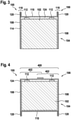
- Fig. 4 schematically shows the battery module 100 with a cover 400 that covers the cell top of the battery cells 102.
- the cover 400 may be formed of bent parts 402 of the side portions 108 of the U-shaped body 104.
- the cover 400 may be formed by bending edges of each of the side portions 108 towards each other.
- the bent parts 402 of the side portions 108 may partially overlap and/or may be clicked or bonded to each other, e.g. by welding.
- a gap between the cell top of the battery cells 102 and the cover 400 may be partially or completely filled with the thermally conductive and electrically isolating material 124.
- the cooling channel 116 may run also through the cover 400 to effectively cool the battery cells 102 at their cell top.
- Fig. 5 schematically shows the battery module 100 with the frame element 106 and a further frame element 106'.
- the further frame element 106' which may be identical to the frame element 106, has a U-shaped body 104' composed of two side portions 108' and a central portion 110', as already described with respect to the frame element 106 of fig. 1 .
- the two side portions 108' and the central portion 110' are different portions of a further cooling plate 114' with an integrated cooling channel 116' for conducting a cooling fluid through the further cooling plate 114'.
- the further cooling plate 114' may have bent portions 118' in the form of ribs 120' protruding from the U-shaped body 104' at each of its corners.
- the frame elements 106, 106' are arranged at opposite sides of the battery cells 102.
- the central portion 110 of the frame element 106 may be in thermal contact with the left side wall of each battery cell 102, whereas one of the side portions 108 of the frame element 106 may be in thermal contact with a left portion of the cell top of each battery cell 102 and another of the side portions 108 of the frame element 106 may be in thermal contact with a left portion of the cell bottom of each battery cell 102.
- the central portion 110' of the further frame element 106' may be in thermal contact with the right side wall of each battery cell 102, whereas one of the side portions 108' of the further frame element 106' may be in thermal contact with a right portion of the cell top of each battery cell 102 and another of the side portions 108' of the further frame element 106' may be in thermal contact with a right portion of the cell bottom of each battery cell 102.
- the battery cells 102 may be stacked by means of a cell holder 500, which will be described in more detail below.
- the cell holder 500 may be at least partially enclosed by the frame elements 106 and 106'.
- Fig. 6 schematically shows an embodiment of the battery module 100 similar to the one depicted in fig. 5 .
- the frame element 106 has only one rib 120 and the further frame element 106' has only one rib 120'.
- the ribs 120, 120' may protrude from one side of the battery module 100, e.g. from its bottom side, and/or may substantially protrude in the same direction.
- Fig. 7 schematically shows an embodiment of the battery module 100 similar to the one depicted in fig. 6 .
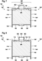
- the battery module 100 has a vent channel 700 for removing gases leaking from the battery cells 102.
- the vent channel 700 is fluidly connected to vents (not shown) of each of the battery cells 102.
- the vents may be positioned at the cell top of the battery cells 102 and may be part of a (prismatic) container of the battery cells 102. Accordingly, the vent channel 700 may extend at the top of the battery module 100 and/or in a longitudinal direction of the battery module 100.
- the vent channel 700 is formed of a bent part 402' of the side portion 108' of the U-shaped body 104' of the further frame element 106'.
- the vent channel 700 may be formed of a bent part of the side portion 108 of the U-shaped body 104 of the frame element 106 or, as shown in fig. 8 , of bent parts of both side portions 108 and 108'.
- vent channel 700 is part of the cover 400.
- the vent channel 700 may be formed of a bent part in which the cooling channel 116, 116' (not shown in fig. 7 ) is integrated.
- the vent channel 700 is formed of a separate channel body 800 and two channel holders 802 that hold the channel body 800 at the top of the battery module 100.
- One of the channel holders 802 may be formed of a bent part of the side portion 108 of the frame element 106 and another of the channel holders 802 may be formed of a bent part of the side portion 108' of the further frame element 106'.
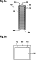
- Fig. 9a schematically shows the battery module 100 from the top.
- the battery module 100 comprises two end plates 900 arranged at opposite sides of the frame element 106.
- the end frame element 106 and the end plates 900 may be components of a leak-proof housing for the battery cells 102.
- Each of the end plates 900 may be arranged on a narrow side of the battery module 100.
- One of the end plates 900 may comprise hydraulic connectors 902 which are respectively coupled to an inlet and an outlet of the cooling channel 116 (not shown) integrated in the frame element 106.
- the end plate 900 may comprise at least one electric connector 904 which is electrically connected to the terminals 112 of the battery cells 102.
- the battery cells 102 may be series-connected and/or parallel-connected to the electric connectors 904.
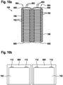
- the battery module 100 may comprise two or more stacks of battery cells 102, each of the stacks arranged in and mechanically supported by a frame element 106, as shown in fig. 10a to 13b .
- the two or more frame elements 106 may be arranged side by side.
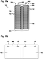
- the hydraulic connectors 902 and electric connectors 904 may be arranged on one side of the battery module 100, e.g. on one of its narrow sides, as shown in fig. 10a , 11a and 12 . Furthermore, all of the connectors 902 and 904 may be integrated in a single end plate 900, as shown in fig. 11a and 12 . The connectors 902, 904 may also be integrated separately in one or both end plates 900.
- the battery cells 102 of different stacks may be series-connected and/or parallel-connected.
- each of the frame elements 106 has its own pair of hydraulic connectors 902, as shown in fig. 10a and 11a .
- the cooling channels 116 of different frame elements 106 may each be coupled to the same pair of hydraulic connectors 902, as shown in fig. 12 and 13a .
- Fig. 14 schematically shows the battery module 100 with a strap tensioning system comprising compression straps 1400 which are tensioned around different portions of the frame element 106 in order to compress the frame element 106, i.e. to press the walls of the frame element 106 against the battery cells 102.
- a strap tensioning system comprising compression straps 1400 which are tensioned around different portions of the frame element 106 in order to compress the frame element 106, i.e. to press the walls of the frame element 106 against the battery cells 102.
- three compression straps 1400 are each tensioned around the narrow side and the wide side of the frame element 106.
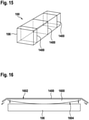
- the compression straps 1400 may be tensioned solely around the wide side of the frame element 106, as shown in fig. 15 .
- the compression straps 1400 may be reinforced or non-reinforced polymeric or metal parts.
- one compression strap 1400 is tensioned around two or more frame elements 106, such as the frame elements 106 shown in fig. 10a to 13b .
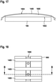
- the compression straps 1400 may each be supported by one or more strap supports 1600, as shown on fig. 16 and 17 .
- the strap supports 1600 are arranged between the compression straps 1400 and an outer surface of the frame element 106.
- Each of the strap supports 1600 may have a flat side 1602 and a convex side 1604 to evenly distribute the pressure caused by the tensioned compression straps 1400 over the surface of the frame element 106.
- the convex side 1604 may face the frame element 106 and the flat side 1602 may face the compression strap 1400 such that the strap support 1600 is bent at its ends towards the frame element 106 when the compression strap 1400 is tensioned (indicated by arrows in fig. 16 ).
- the convex side 1604 faces the compression strap 1400, whereas the flat side 1602 faces the frame element 106 (see fig. 17 ).
- Each of the compression straps 1400 may run across one or both end plates 900.
- a tensioning device 1800 for adjusting the tension of the compression straps 1400 may be integrated, as shown in fig. 18 .
- the tensioning device 1800 may comprise a movable stop 1802 and means for pressing the stop 1802 against the compression straps 1400, such as a screw 1900 with nuts 1902 (see fig. 19 ), a spring 2000 (see fig. 20 ) or a polymer filling 2100 (see fig. 21 ) filled into a cavity of the end plate 900 via an injection hole 2102.
- a screw 1900 with nuts 1902 see fig. 19
- a spring 2000 see fig. 20
- a polymer filling 2100 see fig. 21
- a beam made of a higher-strength material and with an appropriate shape having a relatively high area moment of inertia, such as a U-shape, may be used to apply uniform compression force over the entire length of the frame element 106.
- a beam may for example be mounted directly on the end plates 900 by screws or other means of tensioning and fixation.
- Fig. 22 schematically shows a front view of a battery cell arrangement, where each battery cell 102 is clipped into the cell holder 500 (see also fig. 5 ).
- the cell holder 500 may be a plastic part manufactured in an injection molding process. It is possible that interconnection elements 2200, e.g. for electrically interconnecting the terminals 112 of different battery cells 102 and/or for connecting the terminals 112 to a battery management system, are integrated in the cell holder 500, e.g. mounted to the cell holder 500 and/or embedded into a (molded) plastic material of the cell holder 500.
- Fig. 23 shows the cell holder 500 of fig. 22 viewed from the top.
- the battery cells 102 may be arranged one after another in the cell holder 500.
- the cell holder 500 may hold the battery cells 102 in such a way that adjacent battery cells 102 are separated from each other by an air gap.
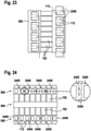
- the cell holder 500 may be composed of a plurality of single cell holder elements 2400, each of which holding one or more battery cells 102.
- the cell holder elements 2400 may be mechanically interconnected to form a stack, e.g. by using snap means 2402 such as noses and corresponding recesses, which may be integral parts of the cell holder elements 2400.
Landscapes
- Chemical & Material Sciences (AREA)
- Chemical Kinetics & Catalysis (AREA)
- Electrochemistry (AREA)
- General Chemical & Material Sciences (AREA)
- Engineering & Computer Science (AREA)
- Manufacturing & Machinery (AREA)
- Secondary Cells (AREA)
- Battery Mounting, Suspending (AREA)
Abstract
Description
- The invention relates to the field of cooling of battery cells. In particular, the invention relates to a battery module.
- Battery cells of a battery module, such as used in electric vehicles, may generate a considerable amount of heat when being charged or discharged at high currents. To remove the heat from the battery cells, cooling means may be integrated in the battery module. Such cooling means may, for example, comprise cooling plates with integrated cooling channels for conducting a cooling fluid.
- To increase the mechanical stability of the battery module, the battery cells may be arranged within a frame-like structure, which mechanically supports each of the battery cells. Depending on the complexity of such a structure, the manufacturing of the battery module may be quite time-consuming.
-
JP 2015-041558 A -
DE 10 2017 215 083 A1 shows a battery housing for accommodating a battery module. The battery housing comprises a bottom wall with an integrated cooling channel for conducting a cooling fluid through the bottom wall. - It is an objective of the invention to provide a battery module with battery cells which are cooled from multiple sides and with a mechanical structure which is relatively easy to manufacture.
- This objective is achieved by the subject-matter of the independent claims. Further exemplary embodiments are evident from the dependent claims and the following description.
- An aspect of the invention relates to a battery module. The battery module may be used as an electric energy storage device for any kind of electric vehicle and/or as a stationary electric energy storage. However, the battery module may also be used in other applications.
- According to an embodiment of the invention, the battery module comprises a plurality of battery cells. The battery cells may be pouch cells or prismatic cells. A prismatic cell may have a substantially prismatic housing, which, for example, may be of metal sheets. In general, a battery cell may be an electrochemical cell with two electrodes and an electrolyte. The battery cell furthermore may comprise a container in which these components are accommodated, such as a pouch or a housing. Each electrode of the battery cell may be electrically connected to a terminal of the battery cell. The two terminals of the battery cell may for example protrude from the container. The battery cells may be electrically connected in series and/or in parallel with each other. Furthermore, the battery cells may be mechanically interconnected and/or stacked. In such a stack, the battery cells may be arranged one after another. The battery module may comprise one or more such stacks. The stacks may by arranged side by side and/or one after another. Different stacks may be electrically connected in series and/or in parallel with each other. It is also possible that the battery module comprises a housing in which the battery cells are accommodated. The housing may be leak-proof. The housing may comprise a support structure for mechanically supporting the battery cells. Such a support structure may for example be a frame in which the battery cells are arranged and which supports them mechanically. The frame may comprise one or more frame elements.
- According to an embodiment of the invention, the battery module comprises a frame element with a U-shaped body, the U-shaped body mechanically supporting the battery cells. A frame element may be a part made of one or more metal sheets, which may be bent and/or bonded, e.g. welded. For example, the frame element may have the form of an elongated beam with a specific profile. Part of the profile may have a U-shaped cross-section, which may represent the body of the frame element. The structural shape of the frame element may for example be achieved by bending a flat metal sheet in a suitable manner. In the case where the battery cells are stacked, the frame element may longitudinally extend in a stacking direction of the battery cells. The U-shaped body may comprise two side portions, corresponding to the two vertical lines of the letter "U", and a central portion interconnecting the two side portions, corresponding to the curved line of the letter "U". Said portions of the U-shaped body may be essentially flat and/or curved. Each of the battery cells may at least partially be arranged between the two side portions of the U-shaped body. In other words, the U-shaped body may at least partially extend along a circumferential border of each of the battery cells such that each of the battery cells is at least partially enclosed by the U-shaped body. In the case of prismatic battery cells, the U-shaped body may for example extend along three different sides of each of the battery cells. Additionally to the U-shaped body, the frame element may comprise further parts, which, for example, may be bent parts formed of one of the portions of the U-shaped body or separate parts mechanically connected to the U-shaped body, such as a cover or an end plate.
- According to an embodiment of the invention, a central portion and two side portions of the U-shaped body are different portions of a cooling plate with an integrated cooling channel for conducting a cooling fluid through the cooling plate. A cooling plate may be a compound of two metal sheets that are at least partially bonded together and enclose a cavity in an un-bonded region. The cavity may have the form of a cooling channel, or cooling channel structure, with an inlet and an outlet for the cooling fluid. The cooling channel may run through each of the portions of the U-shaped body that are in thermal contact with the battery cells. However, it is also possible that the cooling channel is integrated in only some of the portions of the U-shaped body. The cooling channel may also run through one or both bent portions of the cooling plate. For example, the cooling plate may be manufactured in a roll-bond process.
- According to an embodiment of the invention, the central portion of the U-shaped body is connected to each of its side portions via a bent portion of the cooling plate. In other words, the cooling plate may be bent in at least two different regions. A bent portion may be a corner of the U-shaped body, at which the central portion meets with one of the side portions.
- According to an embodiment of the invention, each of the battery cells is in thermal contact with the central portion and at least one of the two side portions of the U-shaped body. In other words, each of the battery cells may contact the central portion and at least one of the two side portions in such a way that heat is conducted from the battery cell, e.g. from a container or pouch of the battery cell, to the respective portion of the U-shaped body. It is possible that each of the battery cells is in thermal contact with up to four different portions of the U-shaped body, i.e. the central portion, the two side portions and a top portion, which may be formed from one or both of the side portions. Each of these portions may be in thermal contact with another portion of the battery cells, such as a cell side, cell front, cell back, cell top or cell bottom. It may be that gaps between each of the battery cells and the U-shaped body are filled with a thermally conductive material, which may also be electrically isolating. The material may be a sticking or non-sticking material or a combination of sticking and non-sticking materials, which facilitates assembly and/or disassembly of the battery module and may be used to enhance the stiffness of the mechanical assembly of the battery module. In the case where the battery cells are prismatic cells having a cell top with cell terminals, a cell bottom and two cell sides facing each other, the U-shaped body may be in thermal contact with at least three of the cell top, the cell bottom and the two cell sides of each of the battery cells.
- According to an embodiment of the invention, the cooling plate is bent in at least one of the bent portions in such a way that at least one rib protrudes from the U-shaped body. The rib may extend in a longitudinal direction of the frame element. The rib may for example be formed by folding the cooling plate, i.e. by bending it with a bending angle of 180°. For example, the U-shaped body may have such a rib at each of its corners. With such ribs, the stiffness of the frame element can be increased.
- According to an embodiment of the invention, the cooling plate has a flat surface on at least one of its sides, wherein each of the battery cells is in thermal contact with the flat surface of the cooling plate. It is possible that the cooling plate is formed with a flat side and a non-flat side which faces the flat side. The cooling plate may be bent in such a way that the flat side of the cooling plate represents the inner surface of the U-shaped body and, thus, faces the battery cells. This maximizes the thermal contact area between the U-shaped body and the battery cells and hence improves the cooling of the battery cells. The flat surface may as well be provided by an external surface of the cooling channel. It is also possible that the cooling plate is bent in such a way that the non-flat side of the cooling plate represents the inner surface of the U-shaped body and, thus, faces the battery cells.
- According to an embodiment of the invention, the rib has a U-shaped or circular cross-section. Such cross-sections are known to increase the rigidity of a beam. The rib may have an open cross-section. Alternatively, the rib may have a closed cross-section. It is also possible that the rib has a rectangular cross-section.
- According to an embodiment of the invention, the cooling channel runs through the central portion and at least one of the two side portions of the U-shaped body. It is possible that the cooling channel also runs through one or both bent portions of the U-shaped body. In this way, the central portion and the one or two side portions of the U-shaped body can be cooled by using a single cooling circuit (instead of using a separate cooling circuit for each of the portions).
- According to an embodiment of the invention, the cooling plate has been formed in a roll-bond process. In such a roll-bond process, two or more sheets of metal may be passed through a pair of rollers under sufficient pressure to bond the sheets. Bonding of the sheets can be controlled by painting a pattern on one of the sheets. This has the effect that only the bare metal surfaces bond. Un-bonded portions can be inflated by heating the sheets such that the coating vaporizes. For example, the U-shaped body may be formed by bending the bonded sheets after or prior to heating them.
- According to an embodiment of the invention, the battery module further comprises a vent channel for conducting gases leaking from the battery cells, the vent channel formed of a bent part of at least one of the side portions of the U-shaped body. Each of the battery cells may have a vent for releasing gases from the interior of the battery cell, e.g. due to evaporation of the electrolyte. The vent channel may be entirely formed of one or more bent parts of the U-shaped body. However, it is also possible that only a portion of the vent channel is formed by one or bent parts of the U-shaped body. For example, it is possible that one or more vent channel holders for holding a (separate) vent channel body are formed of the bent part(s) of the U-shaped body.
- Additionally or alternatively to the vent channel, the battery module further may comprise a cover for covering an open side of the frame element, the cover formed of a bent part of at least one of the side portions of the U-shaped body. The cover may be formed by bending edges of the two side portions towards each other. The two side portions may partially overlap after being bent. Alternatively, the cover may be provided as a separate part. In this case, the bending edges of the frame element may be used as guides for positioning the cover relatively to the frame element and/or as fixation elements for mounting the cover to the frame element.
- The vent channel may be part of the cover of the battery module. For example, the vent channel may be formed of a bent part of the cover.
- According to an embodiment of the invention, the battery module further comprises a cell holder for positioning the battery cells side by side such that two adjacent battery cells are spaced apart from each other, wherein the cell holder has been formed in an injection molding process. The cell holder may be made of plastics or other materials, e.g. a composite material. The cell holder may be adapted for holding each of the battery cells at opposite sides, e.g. at the cell top and the cell bottom and/or at the two cell sides, and/or at corners of the battery cells. For example, the battery cells may each be positioned in or clipped into the cell holder individually. The cell holder may further be adapted for electrically isolating two adjacent battery cells from each other. For example, the cell holder may comprise a plurality of ribs or noses which are arranged between each pair of adjacent battery cells such that direct contact between the adjacent battery cells, e.g. (metal) cans of the battery cells, is avoided. Additionally, the cell holder may comprise mechanical and/or electrical interconnection elements for mechanically and/or electrically interconnecting the battery cells. It is possible that the interconnection elements are embedded into plastic parts of the cell holder during the injection molding process. The cell holder may comprise several cell holder parts, each of which holding the battery cells at a different side. For example, the cell holder may comprise a single part that is designed for holding all of the battery cells at once such that a stack of battery cells is formed.
- According to an embodiment of the invention, the cell holder comprises a plurality of cell holder elements for holding the battery cells, wherein each of the cell holder elements is mechanically connected to at least one adjacent cell holder element. The cell holder elements may each hold one or more battery cells, e.g. two adjacent battery cells. For example, the cell holder elements may be bonded or clipped onto the battery cells. Furthermore, the cell holder elements may be stacked. For example, the cell holder elements may have mutually complementary male and female snap means, such as hooks or noses and corresponding recesses, for mechanically interconnecting the cell holder elements. The cell holder elements may be manufactured in an injection molding process. It is also possible that the cell holder elements each comprise mechanical and/or electrical interconnection elements for mechanically and/or electrically interconnecting the battery cells. These interconnection elements may be embedded into plastic parts of the cell holder element during the injection molding process.
- According to an embodiment of the invention, the battery module further comprises two end plates arranged at opposite sides of the frame element. At least one of the two end plates comprises hydraulic connectors hydraulically connected to the cooling channel. Additionally or alternatively to the hydraulic connectors, at least one of the two end plates comprises electric connectors electrically connected to terminals of each of the battery cells. Alternatively, the end plates may comprise support structures for supporting the hydraulic and/or electric connectors. The end plates may be made of plastics and/or metal, e.g. sheet metal. The end plates may be used to reinforce and/or seal the frame element. The end plates may comprise fixation elements, e.g. for mounting the battery module to a rack or pack or for mounting a battery management system to the battery module. In other words, the frame element and the end plates may form a housing for the battery cells. The housing may be sealed. For example, the end plates may each be positioned at a narrow side of the frame element. The hydraulic connectors may be used to connect the cooling channel to a cooling fluid source. The electric connectors may be used to connect the terminals of the battery cells to a load and/or to a battery management system.
- End plate design and main cooling frame can be arranged in a way that cooling of battery management systems parts can be provided by isolated and thermal conducting path to the main cooling frame.
- It may be that further parts of the battery module, such as a battery management system, are mounted to the frame element and are in thermal contact with the frame element, e.g. with one of the cooled portions of the U-shaped body.
- According to an embodiment of the invention, the hydraulic connectors and the electric connectors are arranged on one side of the frame element. The hydraulic connectors and the electric connectors may be integrated in a single end plate. The hydraulic connectors and the electric connectors may be arranged on a narrow side of the frame element. Alternatively, depending on the battery pack arrangement, the hydraulic connectors may be positioned at two different sides of the frame element.
- According to an embodiment of the invention, the battery module further comprises at least one compression element, such as a compression strap or compression bar, adapted for compressing the frame element at a circumferential border of the frame element. For example, the battery module may comprise two or more compression straps, each of which tensioned around another portion of the frame element. A compression strap may be a metal strap or a belt made from natural and/or synthetic yarns. By compressing the frame element in such a way, (air) gaps between the battery cells and the frame element, i.e. the cooling plate, can be avoided. This improves the heat transfer between the battery cells and the cooling plate. Furthermore, the compression straps may be used for screwless fixation of the battery cells.
- According to an embodiment of the invention, the compression element is a compression strap tensioned around the frame element and at least one strap support is arranged between the compression strap and the frame element, the strap support having a flat side and a convex side. A strap support may be a strip-shaped part. The strap support may be made of plastics or metal. The flat side may be in contact with the frame element, whereas the convex side may be in contact with the compression strap, or vice versa. By using such a strap support, the pressure caused by a compression strap can be distributed evenly over a defined area of the frame element. Alternatively or additionally to the strap support, the compression strap may be tensioned around a vent channel of the battery module, e.g. across a central portion of the vent channel.
- According to an embodiment of the invention, the battery module comprises two end plates arranged at opposite sides of the frame element and one or more compression straps run across the two end plates, at least one of the two end plates comprising a tensioning device adapted for adjusting a tension of each of the compression straps. It is possible that the end plates each have a convex side which is in contact with the compression strap(s) and/or include structures adapted for guiding, aligning and/or positioning the compression strap(s). The tensioning device may comprise a movable stop for adjusting the tension. The stop may for example be moved by means of a spring or a screw. The tensioning device may be adapted for adjusting the tension for each of the compression straps individually. Alternatively, the tensioning may be done once during assembly without any option to compensate or retighten the tension of the compression strap(s).
- According to an embodiment of the invention, the battery module further comprises a further frame element with a U-shaped body, the U-shaped body of the further frame element mechanically supporting the battery cells, wherein each of the battery cells is arranged between the frame element and the further frame element. The frame element and the further frame element may be arranged at opposite sides of the battery cells. The frame element and the further frame may form a shell in which the battery cells are accommodated.
- According to an embodiment of the invention, a central portion and two side portions of the U-shaped body of the further frame element are different portions of a further cooling plate with an integrated cooling channel for conducting a cooling fluid through the further cooling plate, the central portion connected to each of the side portions via a bent portion of the further cooling plate. Each of the battery cells is in thermal contact with the central portion and at least one of the two side portions of the U-shaped body of the further frame element. Furthermore, the further cooling plate is bent in at least one of the bent portions in such a way that at least one rib protrudes from the U-shaped body of the further frame element.
- These and other aspects of the invention will be apparent from and elucidated with reference to the embodiments described hereinafter.
- The subject-matter of the invention will be explained in more detail in the following text with reference to exemplary embodiments which are illustrated in the attached drawings.
-
Fig. 1 schematically shows a front view of a battery module according to an embodiment of the invention. -
Fig. 2 schematically shows a front view of a battery module according to a further embodiment of the invention. -
Fig. 3 schematically shows a front view of a battery module according to a further embodiment of the invention. -
Fig. 4 schematically shows a front view of a battery module with a closed frame element according to an embodiment of the invention. -
Fig. 5 schematically shows a front view of a battery module with two frame elements according to an embodiment of the invention. -
Fig. 6 schematically shows a front view of a battery module with two frame elements according to a further embodiment of the invention. -
Fig. 7 schematically shows a front view of a battery module with a vent channel formed of a frame element according to an embodiment of the invention. -
Fig. 8 schematically shows a front view of a battery module with a vent channel formed of two frame elements according to an embodiment of the invention. -
Fig. 9a schematically shows a top view of a battery module with a stack of battery cells according to an embodiment of the invention. -
Fig. 9b schematically shows a side view of the battery module offig. 9a . -
Fig. 10a schematically shows a top view of a battery module with two stacks of battery cells according to an embodiment of the invention. -
Fig. 10b schematically shows a side view of the battery module offig. 10a . -
Fig. 11a schematically shows a top view of a battery module with two stacks of battery cells according to a further embodiment of the invention. -
Fig. 11b schematically shows a side view of the battery module offig. 11a . -
Fig. 12 schematically shows a top view of a battery module with two stacks of battery cells according to a further embodiment of the invention. -
Fig. 13a schematically shows a top view of a battery module with two stacks of battery cells according to a further embodiment of the invention. -
Fig. 13b schematically shows a side view of the battery module offig. 13a . -
Fig. 14 schematically shows a perspective view of a battery module with a plurality of compression straps according to an embodiment of the invention. -
Fig. 15 schematically shows a perspective view of a battery module with a plurality of compression straps according to a further embodiment of the invention. -
Fig. 16 schematically shows a side view of a strap support for a battery module according to an embodiment of the invention. -
Fig. 17 schematically shows a side view of a strap support for a battery module according to a further embodiment of the invention. -
Fig. 18 schematically shows a front view of the battery module offig. 14 together with a tensioning device. -
Fig. 19 schematically shows a section view of the battery module offig. 18 along line B-B. -
Fig. 20 schematically shows a section view of the battery module offig. 18 along line B-B with a spring. -
Fig. 21 schematically shows a section view of the battery module offig. 18 along line B-B with a polymer filling. -
Fig. 22 schematically shows a front view of a battery cell arrangement for a battery module according to an embodiment of the invention. -
Fig. 23 schematically shows a top view of the battery cell arrangement offig. 22 . -
Fig. 24 schematically shows a top view of a battery cell arrangement for a battery module according to a further embodiment of the invention. - The reference symbols used in the drawings, and their meanings, are listed in summary form in the list of reference symbols. In principle, identical parts are provided with the same reference symbols in the figures.
-
Fig. 1 schematically shows abattery module 100 from the front. Thebattery module 100 comprises a plurality ofbattery cells 102, which may be stacked (fig. 1 shows the cell front of only one of the plurality of battery cells 102). Thebattery cells 102 may each be prismatic cells with a rectangular shape. Alternatively, thebattery module 100 may comprise pouch cells or a combination of pouch cells and prismatic cells. Thebattery cells 102 are arranged in aU-shaped body 104 of aframe element 106. TheU-shaped body 104 comprises twoside portions 108 and acentral portion 110 interconnecting the twoside portions 108. Thebattery cells 102 are arranged between the twoside portions 108 and may be mechanically supported by theU-shaped body 104 at their respective cell bottom and their respective side walls. Theframe element 106 may be open at a front side and a top side, the top side facing thecentral portion 110. Theframe element 106 may also be open at a rear side (not shown). - Each of the
battery cells 102 may have twoterminals 112 at their respective cell top, which each are electrically connected to an electrode inside thebattery cell 102. Thebattery cell 102 may further contain an electrolyte. Theterminals 112 may protrude from the open top side of theU-shaped body 104. - The
frame element 106 is formed of acooling plate 114 with anintegrated cooling channel 116 for conducting a cooling fluid through thecooling plate 114. For example, thecooling plate 114 may be fabricated in a roll-bond process and bent in shape afterwards. Thecooling plate 114 may be bent in two different bending regions such that each of theside portions 112 is connected to thecentral portion 110 via abent portion 118 of thecooling plate 114. - The
cooling plate 114 may be bent in such a way that arib 120 protrudes from theU-shaped body 104 at each of its two corners. The tworibs 120 may protrude in the same direction. Theribs 120 may have a U-shaped cross-section, which, for example, may be formed by bending thecooling plate 114 with a bending angle of 180°. Alternatively, theribs 120 may have a circular cross-section (not shown). In general, theribs 120 may be designed to increase the rigidity of theframe element 106. Theribs 120 may each extend in a longitudinal direction of theframe element 106. Theribs 120 may also protrude in opposite directions, as shown infig. 5 . - The
ribs 120 may also be used as supports for positioning thebattery cells 102 at a certain height above aground 122. - As shown in
fig. 1 , thebattery cells 102 may be in thermal contact with thecentral portion 110 as well as with each of theside portions 108. The coolingchannel 116 may run through each of the threeportions battery cells 102 is effectively removed from thebattery cells 102. - It is possible that the cooling
channel 116 runs from each of theside portions 108 via thebent portions 118 to thecentral portion 110. This has the advantage that only one cooling circuit is required to transport the cooling fluid through all threeportions U-shaped body 104. - The
cooling plate 114 may have a flat surface on one of its side and may be bent in such a way that the flat surface faces thebattery cells 102, i.e. their respective side walls and their respective cell bottom, as shown infig. 1 . - Additionally, the
battery cells 102 may be at least partially embedded in a thermally conductive and electrically isolatingmaterial 124. Thematerial 124 may for example be a liquid gap filler or a gap pad interconnecting the flat surface of thecooling plate 114 with each of the side walls and the cell bottoms of thebattery cells 102. - It may be that the
U-shaped body 104 encloses thebattery cells 102 at their cell bottom and at each of their two side walls, as shown infig. 1 . Alternatively, theU-shaped body 104 may enclose thebattery cells 102 at their cell bottom, at one of their side walls and at their cell top, as shown infig. 2 , or at their cell top and at each of their two side walls, as shown infig. 3 . -
Fig. 4 schematically shows thebattery module 100 with acover 400 that covers the cell top of thebattery cells 102. Thecover 400 may be formed ofbent parts 402 of theside portions 108 of theU-shaped body 104. For example, thecover 400 may be formed by bending edges of each of theside portions 108 towards each other. Thebent parts 402 of theside portions 108 may partially overlap and/or may be clicked or bonded to each other, e.g. by welding. A gap between the cell top of thebattery cells 102 and thecover 400 may be partially or completely filled with the thermally conductive and electrically isolatingmaterial 124. - The cooling
channel 116 may run also through thecover 400 to effectively cool thebattery cells 102 at their cell top. -
Fig. 5 schematically shows thebattery module 100 with theframe element 106 and a further frame element 106'. The further frame element 106', which may be identical to theframe element 106, has a U-shaped body 104' composed of two side portions 108' and a central portion 110', as already described with respect to theframe element 106 offig. 1 . The two side portions 108' and the central portion 110' are different portions of a further cooling plate 114' with an integrated cooling channel 116' for conducting a cooling fluid through the further cooling plate 114'. Similar to theframe element 106, the further cooling plate 114' may have bent portions 118' in the form of ribs 120' protruding from the U-shaped body 104' at each of its corners. - The
frame elements 106, 106' are arranged at opposite sides of thebattery cells 102. - For example, the
central portion 110 of theframe element 106 may be in thermal contact with the left side wall of eachbattery cell 102, whereas one of theside portions 108 of theframe element 106 may be in thermal contact with a left portion of the cell top of eachbattery cell 102 and another of theside portions 108 of theframe element 106 may be in thermal contact with a left portion of the cell bottom of eachbattery cell 102. - Accordingly, the central portion 110' of the further frame element 106' may be in thermal contact with the right side wall of each
battery cell 102, whereas one of the side portions 108' of the further frame element 106' may be in thermal contact with a right portion of the cell top of eachbattery cell 102 and another of the side portions 108' of the further frame element 106' may be in thermal contact with a right portion of the cell bottom of eachbattery cell 102. - The
battery cells 102 may be stacked by means of acell holder 500, which will be described in more detail below. Thecell holder 500 may be at least partially enclosed by theframe elements 106 and 106'. -
Fig. 6 schematically shows an embodiment of thebattery module 100 similar to the one depicted infig. 5 . Infig. 6 , theframe element 106 has only onerib 120 and the further frame element 106' has only one rib 120'. Theribs 120, 120' may protrude from one side of thebattery module 100, e.g. from its bottom side, and/or may substantially protrude in the same direction. -
Fig. 7 schematically shows an embodiment of thebattery module 100 similar to the one depicted infig. 6 . Infig. 7 , thebattery module 100 has avent channel 700 for removing gases leaking from thebattery cells 102. Thevent channel 700 is fluidly connected to vents (not shown) of each of thebattery cells 102. The vents may be positioned at the cell top of thebattery cells 102 and may be part of a (prismatic) container of thebattery cells 102. Accordingly, thevent channel 700 may extend at the top of thebattery module 100 and/or in a longitudinal direction of thebattery module 100. - Exemplarily, the
vent channel 700 is formed of a bent part 402' of the side portion 108' of the U-shaped body 104' of the further frame element 106'. Alternatively, thevent channel 700 may be formed of a bent part of theside portion 108 of theU-shaped body 104 of theframe element 106 or, as shown infig. 8 , of bent parts of bothside portions 108 and 108'. - It is possible that the
vent channel 700 is part of thecover 400. - The
vent channel 700 may be formed of a bent part in which thecooling channel 116, 116' (not shown infig. 7 ) is integrated. - In
fig. 8 , thevent channel 700 is formed of aseparate channel body 800 and twochannel holders 802 that hold thechannel body 800 at the top of thebattery module 100. One of thechannel holders 802 may be formed of a bent part of theside portion 108 of theframe element 106 and another of thechannel holders 802 may be formed of a bent part of the side portion 108' of the further frame element 106'. -
Fig. 9a schematically shows thebattery module 100 from the top. Thebattery module 100 comprises twoend plates 900 arranged at opposite sides of theframe element 106. Theend frame element 106 and theend plates 900 may be components of a leak-proof housing for thebattery cells 102. Each of theend plates 900 may be arranged on a narrow side of thebattery module 100. One of theend plates 900 may comprisehydraulic connectors 902 which are respectively coupled to an inlet and an outlet of the cooling channel 116 (not shown) integrated in theframe element 106. Additionally to thehydraulic connectors 902, theend plate 900 may comprise at least oneelectric connector 904 which is electrically connected to theterminals 112 of thebattery cells 102. Thebattery cells 102 may be series-connected and/or parallel-connected to theelectric connectors 904. - The
battery module 100 may comprise two or more stacks ofbattery cells 102, each of the stacks arranged in and mechanically supported by aframe element 106, as shown infig. 10a to 13b . The two ormore frame elements 106 may be arranged side by side. - The
hydraulic connectors 902 andelectric connectors 904 may be arranged on one side of thebattery module 100, e.g. on one of its narrow sides, as shown infig. 10a ,11a and12 . Furthermore, all of theconnectors single end plate 900, as shown infig. 11a and12 . Theconnectors end plates 900. - The
battery cells 102 of different stacks may be series-connected and/or parallel-connected. - It is possible that each of the
frame elements 106 has its own pair ofhydraulic connectors 902, as shown infig. 10a and11a . Alternatively, the coolingchannels 116 ofdifferent frame elements 106 may each be coupled to the same pair ofhydraulic connectors 902, as shown infig. 12 and 13a . -
Fig. 14 schematically shows thebattery module 100 with a strap tensioning system comprisingcompression straps 1400 which are tensioned around different portions of theframe element 106 in order to compress theframe element 106, i.e. to press the walls of theframe element 106 against thebattery cells 102. Infig. 14 , threecompression straps 1400 are each tensioned around the narrow side and the wide side of theframe element 106. Alternatively, thecompression straps 1400 may be tensioned solely around the wide side of theframe element 106, as shown infig. 15 . The compression straps 1400 may be reinforced or non-reinforced polymeric or metal parts. - It may be that one
compression strap 1400 is tensioned around two ormore frame elements 106, such as theframe elements 106 shown infig. 10a to 13b . - The compression straps 1400 may each be supported by one or more strap supports 1600, as shown on
fig. 16 and17 . The strap supports 1600 are arranged between thecompression straps 1400 and an outer surface of theframe element 106. Each of the strap supports 1600 may have aflat side 1602 and aconvex side 1604 to evenly distribute the pressure caused by the tensionedcompression straps 1400 over the surface of theframe element 106. - For example, the
convex side 1604 may face theframe element 106 and theflat side 1602 may face thecompression strap 1400 such that thestrap support 1600 is bent at its ends towards theframe element 106 when thecompression strap 1400 is tensioned (indicated by arrows infig. 16 ). - However, it is also possible that the
convex side 1604 faces thecompression strap 1400, whereas theflat side 1602 faces the frame element 106 (seefig. 17 ). - Each of the
compression straps 1400 may run across one or bothend plates 900. In at least one of theend plates 900, atensioning device 1800 for adjusting the tension of thecompression straps 1400 may be integrated, as shown infig. 18 . - The
tensioning device 1800 may comprise amovable stop 1802 and means for pressing thestop 1802 against thecompression straps 1400, such as ascrew 1900 with nuts 1902 (seefig. 19 ), a spring 2000 (seefig. 20 ) or a polymer filling 2100 (seefig. 21 ) filled into a cavity of theend plate 900 via aninjection hole 2102. - Alternatively or additionally to the
compression straps 1400, a beam made of a higher-strength material and with an appropriate shape having a relatively high area moment of inertia, such as a U-shape, may be used to apply uniform compression force over the entire length of theframe element 106. Such a beam may for example be mounted directly on theend plates 900 by screws or other means of tensioning and fixation. -
Fig. 22 schematically shows a front view of a battery cell arrangement, where eachbattery cell 102 is clipped into the cell holder 500 (see alsofig. 5 ). Thecell holder 500 may be a plastic part manufactured in an injection molding process. It is possible thatinterconnection elements 2200, e.g. for electrically interconnecting theterminals 112 ofdifferent battery cells 102 and/or for connecting theterminals 112 to a battery management system, are integrated in thecell holder 500, e.g. mounted to thecell holder 500 and/or embedded into a (molded) plastic material of thecell holder 500. -
Fig. 23 shows thecell holder 500 offig. 22 viewed from the top. Thebattery cells 102 may be arranged one after another in thecell holder 500. Thecell holder 500 may hold thebattery cells 102 in such a way thatadjacent battery cells 102 are separated from each other by an air gap. - As shown in
fig. 24 , thecell holder 500 may be composed of a plurality of singlecell holder elements 2400, each of which holding one ormore battery cells 102. Thecell holder elements 2400 may be mechanically interconnected to form a stack, e.g. by using snap means 2402 such as noses and corresponding recesses, which may be integral parts of thecell holder elements 2400. - While the invention has been illustrated and described in detail in the drawings and foregoing description, such illustration and description are to be considered illustrative or exemplary and not restrictive; the invention is not limited to the disclosed embodiments. Other variations to the disclosed embodiments can be understood and effected by those skilled in the art and practicing the claimed invention, from a study of the drawings, the disclosure, and the appended claims. In the claims, the word "comprising" does not exclude other elements or steps, and the indefinite article "a" or "an" does not exclude a plurality. A single processor or superordinate controller or other unit may fulfil the functions of several items recited in the claims. The mere fact that certain measures are recited in mutually different dependent claims does not indicate that a combination of these measures cannot be used to advantage. Any reference signs in the claims should not be construed as limiting the scope.
-
- 100
- battery module
- 102
- battery cell
- 104
- U-shaped body
- 104'
- U-shaped body of further frame element
- 106
- frame element
- 106'
- further frame element
- 108
- side portion
- 108'
- side portion of further frame element
- 110
- central portion
- 110'
- central portion of further frame element
- 112
- terminal
- 114
- cooling plate
- 114'
- further cooling plate
- 116
- cooling channel
- 116'
- cooling channel of further frame element
- 118
- bent portion
- 118'
- bent portion of further frame element
- 120
- rib
- 120'
- rib of further frame element
- 122
- ground
- 124
- thermally conductive and electrically isolating material
- 400
- cover
- 402
- bent part of side portion
- 402'
- bent part of side portion of further frame element
- 500
- cell holder
- 700
- vent channel
- 800
- channel body
- 802
- channel holder
- 900
- end plate
- 902
- hydraulic connector
- 904
- electric connector
- 1400
- compression strap
- 1600
- strap support
- 1602
- flat side
- 1604
- convex side
- 1800
- tensioning device
- 1802
- movable stop
- 1900
- screw
- 1902
- nut
- 2000
- spring
- 2100
- polymer filling
- 2102
- injection hole
- 2200
- interconnection element
- 2400
- cell holder element
- 2402
- snap means
Claims (15)
- A battery module (100), comprising:a plurality of battery cells (102);a frame element (106) with a U-shaped body (104), the U-shaped body (104) mechanically supporting the battery cells (102);wherein a central portion (110) and two side portions (108) of the U-shaped body (104) are different portions of a cooling plate (114) with an integrated cooling channel (116) for conducting a cooling fluid through the cooling plate (114), the central portion (110) connected to each of the side portions (108) via a bent portion (118) of the cooling plate (114);wherein each of the battery cells (102) is in thermal contact with the central portion (110) and at least one of the two side portions (108) of the U-shaped body (104);wherein the cooling plate (114) is bent in at least one of the bent portions (118) in such a way that at least one rib (120) protrudes from the U-shaped body (104).
- The battery module (100) of claim 1,
wherein the cooling plate (114) has a flat surface on at least one of its sides;
wherein each of the battery cells (102) is in thermal contact with the flat surface of the cooling plate (114). - The battery module (100) of claim 1 or 2,
wherein the rib (120) has a U-shaped or circular cross-section. - The battery module (100) of one of the previous claims,
wherein the cooling channel (116) runs through the central portion (110) and at least one of the two side portions (108) of the U-shaped body (104). - The battery module (100) of one of the previous claims,
wherein the cooling plate (114) has been formed in a roll-bond process. - The battery module (100) of one of the previous claims, further comprising:a vent channel (700) for conducting gases leaking from the battery cells (102), the vent channel (700) formed of a bent part (402) of at least one of the side portions (108) of the U-shaped body (104); and/ora cover (400) for covering an open side of the frame element (106), the cover (400) formed of a bent part (402) of at least one of the side portions (108) of the U-shaped body (104).
- The battery module (100) of one of the previous claims, further comprising:a cell holder (500) for positioning the battery cells (102) side by side such that two adjacent battery cells (102) are spaced apart from each other;wherein the cell holder (500) has been formed in an injection molding process.
- The battery module (100) of claim 7,
wherein the cell holder (500) comprises a plurality of cell holder elements (2400) for holding the battery cells (102);
wherein each of the cell holder elements (2400) is mechanically connected to at least one adjacent cell holder element (2400). - The battery module (100) of one of the previous claims, further comprising:two end plates (900) arranged at opposite sides of the frame element (106);wherein at least one of the two end plates (900) comprises hydraulic connectors (902) hydraulically connected to the cooling channel (116, 116') and/or electric connectors (904) electrically connected to terminals (112) of each of the battery cells (102).
- The battery module (100) of claim 9,
wherein the hydraulic connectors (902) and the electric connectors (904) are arranged on one side of the frame element (106). - The battery module (100) of one of the previous claims, further comprising:at least one compression element (1400) adapted for compressing the frame element (106) at a circumferential border of the frame element (106).
- The battery module (100) of claim 11,
wherein the compression element (1400) is a compression strap (1400) tensioned around the frame element (106);
wherein at least one strap support (1600) is arranged between the compression strap (1400) and the frame element (106), the strap support (1600) having a flat side (1602) and a convex side (1604). - The battery module (100) of claim 12, further comprising:two end plates (900) arranged at opposite sides of the frame element (106);wherein the compression strap (1400) runs across the two end plates (900);wherein at least one of the two end plates (900) comprises a tensioning device (1800) adapted for adjusting a tension of the compression strap (1400).
- The battery module (100) of one of the previous claims, further comprising:a further frame element (106') with a U-shaped body (104'), the U-shaped body (104') of the further frame element (106') mechanically supporting the battery cells (102);wherein each of the battery cells (102) is arranged between the frame element (106) and the further frame element (106').
- The battery module (100) of claim 14,
wherein a central portion (110') and two side portions (108') of the U-shaped body (104') of the further frame element (106') are different portions of a further cooling plate (114') with an integrated cooling channel (116') for conducting a cooling fluid through the further cooling plate (114'), the central portion (110') connected to each of the side portions (108') via a bent portion (118') of the further cooling plate (114');
wherein each of the battery cells (102) is in thermal contact with the central portion (110') and at least one of the two side portions (108') of the U-shaped body (104') of the further frame element (106');
wherein the further cooling plate (114') is bent in at least one of the bent portions (118') in such a way that at least one rib (120') protrudes from the U-shaped body (104') of the further frame element (106').
Priority Applications (1)
| Application Number | Priority Date | Filing Date | Title |
|---|---|---|---|
| EP20185528.5A EP3944401A1 (en) | 2020-07-13 | 2020-07-13 | Cooled battery module |
Applications Claiming Priority (1)
| Application Number | Priority Date | Filing Date | Title |
|---|---|---|---|
| EP20185528.5A EP3944401A1 (en) | 2020-07-13 | 2020-07-13 | Cooled battery module |
Publications (1)
| Publication Number | Publication Date |
|---|---|
| EP3944401A1 true EP3944401A1 (en) | 2022-01-26 |
Family
ID=71607805
Family Applications (1)
| Application Number | Title | Priority Date | Filing Date |
|---|---|---|---|
| EP20185528.5A Pending EP3944401A1 (en) | 2020-07-13 | 2020-07-13 | Cooled battery module |
Country Status (1)
| Country | Link |
|---|---|
| EP (1) | EP3944401A1 (en) |
Cited By (3)
| Publication number | Priority date | Publication date | Assignee | Title |
|---|---|---|---|---|
| EP4636906A1 (en) * | 2024-04-18 | 2025-10-22 | Samsung SDI Co., Ltd. | Battery module and method of manufacturing the same |
| EP4636909A1 (en) * | 2024-04-18 | 2025-10-22 | Samsung SDI Co., Ltd. | Battery module and method of manufacturing the same |
| EP4636874A1 (en) * | 2024-04-18 | 2025-10-22 | Samsung SDI Co., Ltd. | Battery unit and method of manufacturing the same |
Citations (6)
| Publication number | Priority date | Publication date | Assignee | Title |
|---|---|---|---|---|
| US20110212355A1 (en) * | 2010-02-26 | 2011-09-01 | Gm Global Technology Operations, Inc. | U-formed cooling plate with solid fins for lithium pouch cells |
| EP2575193A1 (en) * | 2011-09-29 | 2013-04-03 | Lithium Energy Japan | Battery pack |
| US20130316210A1 (en) * | 2011-02-14 | 2013-11-28 | Masahiro Morita | Secondary battery and assembled battery |
| JP2015041558A (en) | 2013-08-23 | 2015-03-02 | 昭和電工株式会社 | Cooling and heating structure of battery pack |
| US20160301051A1 (en) * | 2013-11-22 | 2016-10-13 | Hitachi Automotive Systems, Ltd. | Assembled battery |
| DE102017215083A1 (en) | 2017-08-29 | 2019-02-28 | Volkswagen Aktiengesellschaft | Battery case and method of manufacturing a battery case |
-
2020
- 2020-07-13 EP EP20185528.5A patent/EP3944401A1/en active Pending
Patent Citations (6)
| Publication number | Priority date | Publication date | Assignee | Title |
|---|---|---|---|---|
| US20110212355A1 (en) * | 2010-02-26 | 2011-09-01 | Gm Global Technology Operations, Inc. | U-formed cooling plate with solid fins for lithium pouch cells |
| US20130316210A1 (en) * | 2011-02-14 | 2013-11-28 | Masahiro Morita | Secondary battery and assembled battery |
| EP2575193A1 (en) * | 2011-09-29 | 2013-04-03 | Lithium Energy Japan | Battery pack |
| JP2015041558A (en) | 2013-08-23 | 2015-03-02 | 昭和電工株式会社 | Cooling and heating structure of battery pack |
| US20160301051A1 (en) * | 2013-11-22 | 2016-10-13 | Hitachi Automotive Systems, Ltd. | Assembled battery |
| DE102017215083A1 (en) | 2017-08-29 | 2019-02-28 | Volkswagen Aktiengesellschaft | Battery case and method of manufacturing a battery case |
Cited By (3)
| Publication number | Priority date | Publication date | Assignee | Title |
|---|---|---|---|---|
| EP4636906A1 (en) * | 2024-04-18 | 2025-10-22 | Samsung SDI Co., Ltd. | Battery module and method of manufacturing the same |
| EP4636909A1 (en) * | 2024-04-18 | 2025-10-22 | Samsung SDI Co., Ltd. | Battery module and method of manufacturing the same |
| EP4636874A1 (en) * | 2024-04-18 | 2025-10-22 | Samsung SDI Co., Ltd. | Battery unit and method of manufacturing the same |
Similar Documents
| Publication | Publication Date | Title |
|---|---|---|
| CN114207924B (en) | Battery module, battery pack including the battery module, and vehicle | |
| US11784360B2 (en) | Battery module | |
| US10038226B2 (en) | Cooling plate for lithium-ion battery pack | |
| KR102640329B1 (en) | Battery module | |
| KR100896131B1 (en) | Medium and large battery module | |
| EP3944401A1 (en) | Cooled battery module | |
| US11588193B2 (en) | Battery module | |
| KR101326182B1 (en) | Battery Module Based upon Unit Module Having External Covering Member and Cartridge | |
| KR101393436B1 (en) | Battery module and cell-cartridge | |
| GB2535546A (en) | Battery modules and methods for their manufacture | |
| CN110783659A (en) | Accumulator device | |
| KR20140109982A (en) | Battery module having a battery module housing and battery cells | |
| KR101465491B1 (en) | Battery module and cell-cartridge | |
| CN215008506U (en) | Battery module for battery pack | |
| KR102922440B1 (en) | Battery Pack With Improved Battery Cell Lifetime And Device Including It | |
| KR102848191B1 (en) | Battery Cell, Battery Module Having The Same, and Battery Pack | |
| EP3641011A1 (en) | Battery module | |
| KR102699572B1 (en) | Bettery module | |
| KR102717207B1 (en) | Battery module | |
| KR102802529B1 (en) | Battery module and battery pack including the same | |
| CN210535716U (en) | Lower shell of battery pack and battery pack | |
| JP7350419B2 (en) | Battery modules, battery packs containing them, and methods of transporting battery modules | |
| CN115911639A (en) | power storage device | |
| EP4462569A1 (en) | Battery pack | |
| EP3762993B1 (en) | Battery cell arrangement |
Legal Events
| Date | Code | Title | Description |
|---|---|---|---|
| PUAI | Public reference made under article 153(3) epc to a published international application that has entered the european phase |
Free format text: ORIGINAL CODE: 0009012 |
|
| STAA | Information on the status of an ep patent application or granted ep patent |
Free format text: STATUS: THE APPLICATION HAS BEEN PUBLISHED |
|
| AK | Designated contracting states |
Kind code of ref document: A1 Designated state(s): AL AT BE BG CH CY CZ DE DK EE ES FI FR GB GR HR HU IE IS IT LI LT LU LV MC MK MT NL NO PL PT RO RS SE SI SK SM TR |
|
| STAA | Information on the status of an ep patent application or granted ep patent |
Free format text: STATUS: REQUEST FOR EXAMINATION WAS MADE |
|
| 17P | Request for examination filed |
Effective date: 20220628 |
|
| RBV | Designated contracting states (corrected) |
Designated state(s): AL AT BE BG CH CY CZ DE DK EE ES FI FR GB GR HR HU IE IS IT LI LT LU LV MC MK MT NL NO PL PT RO RS SE SI SK SM TR |