EP3944387B1 - Rechargeable battery - Google Patents
Rechargeable battery Download PDFInfo
- Publication number
- EP3944387B1 EP3944387B1 EP21179265.0A EP21179265A EP3944387B1 EP 3944387 B1 EP3944387 B1 EP 3944387B1 EP 21179265 A EP21179265 A EP 21179265A EP 3944387 B1 EP3944387 B1 EP 3944387B1
- Authority
- EP
- European Patent Office
- Prior art keywords
- electrode
- terminal
- cap plate
- electrode assembly
- angle
- Prior art date
- Legal status (The legal status is an assumption and is not a legal conclusion. Google has not performed a legal analysis and makes no representation as to the accuracy of the status listed.)
- Active
Links
Images


Classifications
-
- H—ELECTRICITY
- H01—ELECTRIC ELEMENTS
- H01M—PROCESSES OR MEANS, e.g. BATTERIES, FOR THE DIRECT CONVERSION OF CHEMICAL ENERGY INTO ELECTRICAL ENERGY
- H01M10/00—Secondary cells; Manufacture thereof
- H01M10/04—Construction or manufacture in general
- H01M10/0422—Cells or battery with cylindrical casing
- H01M10/0427—Button cells
-
- H—ELECTRICITY
- H01—ELECTRIC ELEMENTS
- H01M—PROCESSES OR MEANS, e.g. BATTERIES, FOR THE DIRECT CONVERSION OF CHEMICAL ENERGY INTO ELECTRICAL ENERGY
- H01M50/00—Constructional details or processes of manufacture of the non-active parts of electrochemical cells other than fuel cells, e.g. hybrid cells
- H01M50/50—Current conducting connections for cells or batteries
- H01M50/528—Fixed electrical connections, i.e. not intended for disconnection
-
- H—ELECTRICITY
- H01—ELECTRIC ELEMENTS
- H01M—PROCESSES OR MEANS, e.g. BATTERIES, FOR THE DIRECT CONVERSION OF CHEMICAL ENERGY INTO ELECTRICAL ENERGY
- H01M50/00—Constructional details or processes of manufacture of the non-active parts of electrochemical cells other than fuel cells, e.g. hybrid cells
- H01M50/10—Primary casings; Jackets or wrappings
- H01M50/172—Arrangements of electric connectors penetrating the casing
- H01M50/174—Arrangements of electric connectors penetrating the casing adapted for the shape of the cells
- H01M50/181—Arrangements of electric connectors penetrating the casing adapted for the shape of the cells for button or coin cells
-
- H—ELECTRICITY
- H01—ELECTRIC ELEMENTS
- H01M—PROCESSES OR MEANS, e.g. BATTERIES, FOR THE DIRECT CONVERSION OF CHEMICAL ENERGY INTO ELECTRICAL ENERGY
- H01M10/00—Secondary cells; Manufacture thereof
- H01M10/05—Accumulators with non-aqueous electrolyte
- H01M10/052—Li-accumulators
- H01M10/0525—Rocking-chair batteries, i.e. batteries with lithium insertion or intercalation in both electrodes; Lithium-ion batteries
-
- H—ELECTRICITY
- H01—ELECTRIC ELEMENTS
- H01M—PROCESSES OR MEANS, e.g. BATTERIES, FOR THE DIRECT CONVERSION OF CHEMICAL ENERGY INTO ELECTRICAL ENERGY
- H01M50/00—Constructional details or processes of manufacture of the non-active parts of electrochemical cells other than fuel cells, e.g. hybrid cells
- H01M50/10—Primary casings; Jackets or wrappings
- H01M50/102—Primary casings; Jackets or wrappings characterised by their shape or physical structure
- H01M50/109—Primary casings; Jackets or wrappings characterised by their shape or physical structure of button or coin shape
-
- H—ELECTRICITY
- H01—ELECTRIC ELEMENTS
- H01M—PROCESSES OR MEANS, e.g. BATTERIES, FOR THE DIRECT CONVERSION OF CHEMICAL ENERGY INTO ELECTRICAL ENERGY
- H01M50/00—Constructional details or processes of manufacture of the non-active parts of electrochemical cells other than fuel cells, e.g. hybrid cells
- H01M50/10—Primary casings; Jackets or wrappings
- H01M50/116—Primary casings; Jackets or wrappings characterised by the material
- H01M50/117—Inorganic material
- H01M50/119—Metals
-
- H—ELECTRICITY
- H01—ELECTRIC ELEMENTS
- H01M—PROCESSES OR MEANS, e.g. BATTERIES, FOR THE DIRECT CONVERSION OF CHEMICAL ENERGY INTO ELECTRICAL ENERGY
- H01M50/00—Constructional details or processes of manufacture of the non-active parts of electrochemical cells other than fuel cells, e.g. hybrid cells
- H01M50/10—Primary casings; Jackets or wrappings
- H01M50/14—Primary casings; Jackets or wrappings for protecting against damage caused by external factors
- H01M50/143—Fireproof; Explosion-proof
-
- H—ELECTRICITY
- H01—ELECTRIC ELEMENTS
- H01M—PROCESSES OR MEANS, e.g. BATTERIES, FOR THE DIRECT CONVERSION OF CHEMICAL ENERGY INTO ELECTRICAL ENERGY
- H01M50/00—Constructional details or processes of manufacture of the non-active parts of electrochemical cells other than fuel cells, e.g. hybrid cells
- H01M50/10—Primary casings; Jackets or wrappings
- H01M50/147—Lids or covers
- H01M50/148—Lids or covers characterised by their shape
- H01M50/153—Lids or covers characterised by their shape for button or coin cells
-
- H—ELECTRICITY
- H01—ELECTRIC ELEMENTS
- H01M—PROCESSES OR MEANS, e.g. BATTERIES, FOR THE DIRECT CONVERSION OF CHEMICAL ENERGY INTO ELECTRICAL ENERGY
- H01M50/00—Constructional details or processes of manufacture of the non-active parts of electrochemical cells other than fuel cells, e.g. hybrid cells
- H01M50/10—Primary casings; Jackets or wrappings
- H01M50/147—Lids or covers
- H01M50/148—Lids or covers characterised by their shape
- H01M50/154—Lid or cover comprising an axial bore for receiving a central current collector
-
- H—ELECTRICITY
- H01—ELECTRIC ELEMENTS
- H01M—PROCESSES OR MEANS, e.g. BATTERIES, FOR THE DIRECT CONVERSION OF CHEMICAL ENERGY INTO ELECTRICAL ENERGY
- H01M50/00—Constructional details or processes of manufacture of the non-active parts of electrochemical cells other than fuel cells, e.g. hybrid cells
- H01M50/10—Primary casings; Jackets or wrappings
- H01M50/147—Lids or covers
- H01M50/155—Lids or covers characterised by the material
- H01M50/157—Inorganic material
- H01M50/159—Metals
-
- H—ELECTRICITY
- H01—ELECTRIC ELEMENTS
- H01M—PROCESSES OR MEANS, e.g. BATTERIES, FOR THE DIRECT CONVERSION OF CHEMICAL ENERGY INTO ELECTRICAL ENERGY
- H01M50/00—Constructional details or processes of manufacture of the non-active parts of electrochemical cells other than fuel cells, e.g. hybrid cells
- H01M50/10—Primary casings; Jackets or wrappings
- H01M50/183—Sealing members
- H01M50/186—Sealing members characterised by the disposition of the sealing members
- H01M50/188—Sealing members characterised by the disposition of the sealing members the sealing members being arranged between the lid and terminal
-
- H—ELECTRICITY
- H01—ELECTRIC ELEMENTS
- H01M—PROCESSES OR MEANS, e.g. BATTERIES, FOR THE DIRECT CONVERSION OF CHEMICAL ENERGY INTO ELECTRICAL ENERGY
- H01M50/00—Constructional details or processes of manufacture of the non-active parts of electrochemical cells other than fuel cells, e.g. hybrid cells
- H01M50/30—Arrangements for facilitating escape of gases
- H01M50/342—Non-re-sealable arrangements
-
- H—ELECTRICITY
- H01—ELECTRIC ELEMENTS
- H01M—PROCESSES OR MEANS, e.g. BATTERIES, FOR THE DIRECT CONVERSION OF CHEMICAL ENERGY INTO ELECTRICAL ENERGY
- H01M50/00—Constructional details or processes of manufacture of the non-active parts of electrochemical cells other than fuel cells, e.g. hybrid cells
- H01M50/50—Current conducting connections for cells or batteries
- H01M50/531—Electrode connections inside a battery casing
- H01M50/533—Electrode connections inside a battery casing characterised by the shape of the leads or tabs
-
- H—ELECTRICITY
- H01—ELECTRIC ELEMENTS
- H01M—PROCESSES OR MEANS, e.g. BATTERIES, FOR THE DIRECT CONVERSION OF CHEMICAL ENERGY INTO ELECTRICAL ENERGY
- H01M50/00—Constructional details or processes of manufacture of the non-active parts of electrochemical cells other than fuel cells, e.g. hybrid cells
- H01M50/50—Current conducting connections for cells or batteries
- H01M50/543—Terminals
- H01M50/545—Terminals formed by the casing of the cells
-
- H—ELECTRICITY
- H01—ELECTRIC ELEMENTS
- H01M—PROCESSES OR MEANS, e.g. BATTERIES, FOR THE DIRECT CONVERSION OF CHEMICAL ENERGY INTO ELECTRICAL ENERGY
- H01M50/00—Constructional details or processes of manufacture of the non-active parts of electrochemical cells other than fuel cells, e.g. hybrid cells
- H01M50/50—Current conducting connections for cells or batteries
- H01M50/543—Terminals
- H01M50/547—Terminals characterised by the disposition of the terminals on the cells
- H01M50/548—Terminals characterised by the disposition of the terminals on the cells on opposite sides of the cell
-
- H—ELECTRICITY
- H01—ELECTRIC ELEMENTS
- H01M—PROCESSES OR MEANS, e.g. BATTERIES, FOR THE DIRECT CONVERSION OF CHEMICAL ENERGY INTO ELECTRICAL ENERGY
- H01M50/00—Constructional details or processes of manufacture of the non-active parts of electrochemical cells other than fuel cells, e.g. hybrid cells
- H01M50/50—Current conducting connections for cells or batteries
- H01M50/543—Terminals
- H01M50/552—Terminals characterised by their shape
- H01M50/559—Terminals adapted for cells having curved cross-section, e.g. round, elliptic or button cells
-
- H—ELECTRICITY
- H01—ELECTRIC ELEMENTS
- H01M—PROCESSES OR MEANS, e.g. BATTERIES, FOR THE DIRECT CONVERSION OF CHEMICAL ENERGY INTO ELECTRICAL ENERGY
- H01M50/00—Constructional details or processes of manufacture of the non-active parts of electrochemical cells other than fuel cells, e.g. hybrid cells
- H01M50/50—Current conducting connections for cells or batteries
- H01M50/572—Means for preventing undesired use or discharge
- H01M50/574—Devices or arrangements for the interruption of current
- H01M50/581—Devices or arrangements for the interruption of current in response to temperature
-
- H—ELECTRICITY
- H01—ELECTRIC ELEMENTS
- H01M—PROCESSES OR MEANS, e.g. BATTERIES, FOR THE DIRECT CONVERSION OF CHEMICAL ENERGY INTO ELECTRICAL ENERGY
- H01M2200/00—Safety devices for primary or secondary batteries
- H01M2200/10—Temperature sensitive devices
-
- Y—GENERAL TAGGING OF NEW TECHNOLOGICAL DEVELOPMENTS; GENERAL TAGGING OF CROSS-SECTIONAL TECHNOLOGIES SPANNING OVER SEVERAL SECTIONS OF THE IPC; TECHNICAL SUBJECTS COVERED BY FORMER USPC CROSS-REFERENCE ART COLLECTIONS [XRACs] AND DIGESTS
- Y02—TECHNOLOGIES OR APPLICATIONS FOR MITIGATION OR ADAPTATION AGAINST CLIMATE CHANGE
- Y02E—REDUCTION OF GREENHOUSE GAS [GHG] EMISSIONS, RELATED TO ENERGY GENERATION, TRANSMISSION OR DISTRIBUTION
- Y02E60/00—Enabling technologies; Technologies with a potential or indirect contribution to GHG emissions mitigation
- Y02E60/10—Energy storage using batteries
-
- Y—GENERAL TAGGING OF NEW TECHNOLOGICAL DEVELOPMENTS; GENERAL TAGGING OF CROSS-SECTIONAL TECHNOLOGIES SPANNING OVER SEVERAL SECTIONS OF THE IPC; TECHNICAL SUBJECTS COVERED BY FORMER USPC CROSS-REFERENCE ART COLLECTIONS [XRACs] AND DIGESTS
- Y02—TECHNOLOGIES OR APPLICATIONS FOR MITIGATION OR ADAPTATION AGAINST CLIMATE CHANGE
- Y02P—CLIMATE CHANGE MITIGATION TECHNOLOGIES IN THE PRODUCTION OR PROCESSING OF GOODS
- Y02P70/00—Climate change mitigation technologies in the production process for final industrial or consumer products
- Y02P70/50—Manufacturing or production processes characterised by the final manufactured product
Definitions
- the present invention relates to a rechargeable battery.
- a rechargeable battery differs from a primary battery in that it can be repeatedly charged and discharged, while the latter is incapable of being recharged.
- a low-capacity rechargeable battery is used in a portable electronic device, such as a mobile phone, a notebook computer, and a camcorder, and a large-capacity rechargeable battery is widely used as a power source for driving a motor of a hybrid vehicle and the like.
- the Li-ion rechargeable battery As typical rechargeable batteries, there are a nickel-cadmium (Ni-Cd) battery, a nickel-hydrogen (Ni-MH) battery, a lithium (Li) battery, a lithium ion (Li-ion) rechargeable battery, etc.
- the Li-ion rechargeable battery has an operating voltage that is three times as high as those of the Ni-Cd battery and the Ni-MH battery that are widely used as a power supply of portable electronic devices.
- the Li-ion rechargeable battery has been widely used because an energy density per unit weight thereof is high.
- the ultra-small rechargeable battery may include a coin cell or a button cell. Since an entire height of the coin cell or button cell is low, a difference in battery capacity may occur depending on an inner structure thereof.
- an electrolyte solution may not be easily supplied into an electrode assembly.
- CN 204596910 U discloses a rechargeable battery comprising electrode tabs having an inclined portion.
- an ultra-small rechargeable battery in which an electrolyte solution may easily flow into an electrode assembly is provided.
- a rechargeable battery is provided as defined in claim 1.
- the first angle may be 10 degrees or less, preferably 5 degrees or less.
- the at least one electrode tab may include a first electrode tab connecting the first electrode and the bottom surface of the case; and a second electrode tab connecting the second electrode and the electrode terminal, and the first electrode may be a negative electrode and the second electrode may be a positive electrode.
- the inclined portion of the first electrode tab may be connected to the bottom surface of the case at a second angle
- the inclined portion of the second electrode tab may be connected to a lower surface of the electrode terminal at a third angle
- the second angle and the third angle may be the same as the first angle
- a length of the at least one electrode tab may be larger than half of a diameter of the electrode assembly, and may be smaller than the diameter of the electrode assembly.
- the electrode terminal may include a flange portion covering the terminal hole and overlapping the cap plate, and a protrusion integrally formed with the flange portion and protruding from the flange portion toward the terminal hole.
- An outer surface of the protrusion may have a curved surface and an inclined surface, and a distance from the curved surface to an end portion of the cap plate exposed by the terminal hole may be shorter than a distance from the inclined surface to the end portion of the cap plate exposed by the terminal hole, and the distance to the end portion of the cap plate exposed by the terminal hole may become longer moving closer to an end portion of the inclined portion.
- the rechargeable battery may further include a thermal-fusion layer between the cap plate and the flange portion and insulation-bonding the cap plate and the flange portion.
- the thermal-fusion layer may melt at a predetermined temperature.
- an electrode tab is obliquely connected to an electrode assembly, such that the electrode tab does not prevent the electrolyte solution from moving into the electrode assembly and electrolyte solution may be easily supplied into the electrode assembly due to the electrode tab.
- first electrode 12 second electrode 13: separator 30: step portion 41: flange portion 42: protrusion 100: electrode assembly 200: case 300: cap plate 400: electrode terminal 500: thermal-fusion layer
- a rechargeable battery according to the present invention is an ultra-small rechargeable battery, and may include a coin cell or a button cell, but the present invention is not limited thereto, and may include a cylindrical or pin-type cell.
- the coin cell or the button cell is a thin coin-type or button-type cell, and may mean a battery having a ratio (height/diameter) of a height to a diameter of 1 or less, but is not limited thereto.
- the coin cell or the button cell is cylindrical, and a horizontal cross-section is circular, but the present invention is not limited thereto, and a horizontal cross-section may be oval or polygonal.
- the diameter may mean a maximum distance of the cell based on a horizontal direction of the cell
- the height may mean a maximum distance (distance from a flat bottom surface thereof to a flat uppermost surface) of the cell based on a vertical direction of the cell.
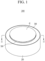
- FIG. 1 is a perspective view of a rechargeable battery according to an embodiment of the present invention
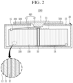
- FIG. 2 is a cross-sectional view taken along the line II-II of FIG. 1
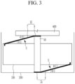
- FIG. 3 is a schematic view illustrating an electrode tab according to an embodiment of the present invention.
- a rechargeable battery 1000 includes an electrode assembly 100, a case 200 having an inner space accommodating the electrode assembly 100, a cap plate 300 coupled to the case 200 to seal the inner space, and an electrode terminal 400 penetrating through the cap plate to be electrically connected to the electrode assembly 100.
- a lower surface of the electrode assembly 100 faces an inner bottom surface of the case 200, and an upper surface of the electrode assembly 100 faces a lower surface of the cap plate 300 covering an opening 21 of the case 200.
- the electrode assembly 100 includes a first electrode 11, a second electrode 12, and a separator 13, and the first electrode 11 and the second electrode 12 are positioned on both sides of the separator 13, which is an electrically insulating material.
- the first electrode 11 includes an electrode active region, which is an area in which an active material is applied to a thin plate formed of a long strip-shaped metal foil, and an electrode uncoated region, which is an area to which no active material is applied; and a first electrode tab 14 may be connected to the electrode uncoated region.
- the electrode uncoated region may be respectively formed at opposite end portions of the electrode active region, that is, at respective end portions of the first electrode 11 in a length direction thereof, but is not limited thereto, and, in an embodiment, may be formed only at one end portion.
- the first electrode 11 may be a negative electrode, and in the electrode active region, an active material, such as graphite or carbon, may be coated on a metal foil, such as copper or nickel.
- the first electrode tab 14 is electrically connected to the electrode uncoated region of the first electrode 11 of the electrode assembly 100, and protrudes to the outside of the electrode assembly 100 to be welded to a bottom surface of the case 200 to electrically connect the first electrode 11 to the case 200. Accordingly, the case 200 connected to the first electrode 11 with the first electrode tab 14 has the same polarity as the first electrode 11.
- a length of the first electrode tab 14 may be longer than half of a diameter, or longer than a radius, of the electrode assembly 100, and may be shorter than the diameter such that the first electrode tab 14 may facilitate a welding process and may not be wrinkled.
- the first electrode tab 14 may have an inclined portion 4 obliquely connected to the electrode assembly 100 at an angle of 10 degrees or less. That is, a surface of the inclined portion 4 facing the electrode assembly 100 may have a first angle ⁇ 1 of 10 degrees or less with respect to a lower surface of the electrode assembly 100.
- the lower surface of the electrode assembly 100 is a virtual horizontal surface on which an end portion of a protruding membrane is positioned and that is parallel to an inner surface of the case 200.
- the first electrode tab 14 may have a flat portion 5 that extends from the inclined portion 4 and is attached to the bottom surface of the case 200.
- a surface of the flat portion 5 is parallel to and attached to the bottom surface of the case 200
- the inclined portion 4 may be connected to the bottom surface of the case 200 at a second angle ⁇ 2.
- the second angle ⁇ 2 may be the same as the first angle ⁇ 1.
- the flat portion 5 may be connected to the inclined portion 4 at an obtuse angle, and, in an embodiment, the flat portion 5 may be pressed by a center pin 50.
- the electrode assembly 100 is spaced apart from the inclined portion by a space S, such that an electrolyte solution may not be obstructed by the first electrode tab 14 to easily flow into the electrode assembly 100.
- the second electrode 12 includes an electrode active region, which is an area in which an active material is applied to a thin plate formed of a long strip-shaped metal foil, and an electrode uncoated region, which is an area to which no active material is applied; and a second electrode tab 15 may be connected to the electrode uncoated region.
- the electrode uncoated region may be respectively formed at opposite end portions of the electrode active region, that is, at respective end portions of the second electrode 12 in a length direction thereof, but is not limited thereto, and, in an embodiment, may be formed only at one end portion.
- the second electrode tab 15 may be connected to the electrode uncoated region of the second electrode 12, and the second electrode tab 15 may protrude from the second electrode 12 to be electrically connected to the electrode terminal 400.
- the second electrode tab 15 may be made of an electrically conductive material, such as nickel or copper, and may be connected to the electrode uncoated region by welding. In an embodiment, the welding may be laser welding.
- the second electrode 12 may be a positive electrode, and in the electrode active region, an active material, such as a transition metal oxide, may be coated on a metal foil, such as aluminum.
- the second electrode tab 15 is electrically connected to the electrode uncoated region of the second electrode 12 of the electrode assembly 100, and protrudes to the outside of the electrode assembly 100 to be welded to a lower surface of the electrode terminal 400 to electrically connect the second electrode 12 to the electrode terminal 400.
- the electrode terminal 400 has the same polarity as that of the second electrode 12.
- a length of the second electrode tab 15 may be longer than half of a diameter, or longer than a radius, of the electrode assembly 100, and may be shorter than the diameter such that the second electrode tab 15 may facilitate a welding process and may not be wrinkled.
- the second electrode tab 15 may have an inclined portion 7 obliquely connected to the electrode assembly 100 at an angle of 10 degrees or less. That is, a surface of the inclined portion 7 facing the electrode assembly 100 may have a first angle ⁇ 1 of 10 degrees or less with respect to an upper surface of the electrode assembly 100.
- the upper surface of the electrode assembly 100 is a virtual horizontal surface on which an end portion of a protruding membrane is positioned and that is parallel to an inner surface of the cap plate 300.
- the second electrode tab 15 may have a flat portion 8 that extends from the inclined portion 7 and is attached to a lower surface of a protrusion of the terminal electrode 400.
- a surface of the flat portion 8 is attached to a lower surface of the terminal electrode 400 in parallel, and the inclined portion 8 may be connected to the lower surface of the terminal electrode 400 at a third angle ⁇ 3.
- the third angle ⁇ 3 may be the same as the first angle ⁇ 1.
- the flat portion 8 may be pressed by the center pin 50.
- the flat portion 8 may be connected to the inclined portion 7 at an obtuse angle.
- the electrode assembly 100 is spaced apart from the inclined portion by a space S, such that an electrolyte solution may not be obstructed by the second electrode tab 15 to easily flow into the electrode assembly 100.
- the separator 13 is positioned between the first electrode 11 and the second electrode 12 to prevent or substantially prevent a short circuit therebetween, and allows lithium ions to move.
- the separator 13 may be made of, for example, any of polyethylene, polypropylene, and a composite film of polyethylene and polypropylene.
- a width of the separator 13 may be equal to or larger than that of the first electrode 11 or the second electrode 12, and the width of first electrode 11 may be larger than that of the second electrode 12.
- the width is a length in a direction in which the electrode assembly 100 is inserted into the case.
- the electrode assembly 100 may have a jelly roll shape in which the first electrode 11, the separator 13, and the second electrode 12 overlap to be wound around a rotation axis, but is not limited thereto, and may have a structure (not shown) in which a sheet-type first electrode, a separator, and a second electrode are repeatedly stacked.
- the electrode assembly 100 may be covered with an insulating tape (not shown) along a diameter-direction external circumferential surface.
- the insulating tape electrically insulates the external circumferential surface of the electrode assembly 100 from the inner surface of the case 200, while protecting the outside of the electrode assembly 100.
- the electrode assembly 100 may be housed in the case 200 with an electrolyte solution in a direction parallel to the rotation axis of the electrode assembly 100.
- the electrolyte solution may be composed of an organic solvent, such as any of EC, PC, DEC, and EMC, and a Li salt, such as LiPF 6 and LiBF 4 .
- the electrolyte solution may be in a liquid, solid, or gel state.
- the center pin 50 penetrating through a center of the electrode assembly 100 in a vertical direction may be positioned at the center of the electrode assembly 100, and the center pin 50 may support the first electrode tab 14 and the second electrode tab 15.
- a diameter of the center pin 50 may be approximately 1.2 mm.
- the case 200 has a space in which the electrode assembly 100 and an electrolyte solution are accommodated, and an opening 21 of which one side is open.
- the electrode assembly 100 may be inserted through the opening 21 to be accommodated in the inner space of the case 200.
- the case 200 may have a cylindrical shape having a low height, but is not limited thereto, and may have any of various known shapes.
- the case 200 may accommodate any of various known electrolyte solutions along with the electrode assembly 100, and, in an embodiment, may be made of stainless steel.
- the inner bottom surface of the case 200 is connected to the first electrode 11 of the electrode assembly 100 by the first electrode tab 14, such that the case 200 has the same polarity as that of the first electrode 11.
- An outer surface of the case 200 may be a first electrode terminal of the rechargeable battery 1000, and an outer surface of the electrode terminal 400 may be a second electrode terminal of the rechargeable battery 1000.
- the cap plate 300 closes and seals the inner space of the case 200, the electrode terminal 400 may be coupled to the opening 21 of the case 200, and the cap plate 300 may be coupled to the opening 21 by welding.
- the cap plate 300 may be formed to have a shape corresponding to the opening 21, and a step portion 30 may be formed in the opening 21 such that the cap plate 300 may be easily mounted.
- the cap plate 300 is coupled to the case 200 and has the same polarity as that of the first electrode 11, and an outer surface of the cap plate 300 may be the first electrode terminal of the rechargeable battery 1000.
- the cap plate 300 includes stainless steel, but is not limited thereto, and may include a metal such as aluminum, nickel, or copper.
- the electrode terminal 400 is insulated from and bonded to the cap plate 300 having a different polarity from that of the electrode terminal 400, and may be electrically connected to the second electrode 12 of the electrode assembly 100 through the terminal hole 31 of the cap plate 300. Therefore, the electrode terminal 400 may be the second electrode terminal of the rechargeable battery 1000.
- the electrode terminal 400 may include stainless steel, but is not limited thereto, and may include a metal such as aluminum, nickel, or copper.
- case 200 and the cap plate 300 may be made of a same material.
- the electrode terminal 400 may include a flange portion 41 and a protrusion 42, the flange portion 41 may have a wider area (or diameter) than the protrusion 42, and the flange portion 41 has a thinner thickness than the protrusion 42.
- the protrusion 42 and the flange portion 41 may be integrally formed.
- the protrusion 42 of the electrode terminal 400 is inserted into the terminal hole 31, and covers the terminal hole 31 of the cap plate 300 together with the flange portion 41 to seal the inside of the case 200.
- the protrusion 42 of the electrode terminal 400 is electrically connected to the second electrode tab 15 of the electrode assembly 100, such that the electrode terminal 400 has the same polarity as the second electrode 12.
- the outer surface of the flange part 41 may be the second electrode terminal of the rechargeable battery 1000.
- FIG. 4 is an enlarged view of a region "A" of FIG. 2 .
- an outer surface of the protrusion 42 includes a curved surface CS and an inclined surface IS.
- the protrusion 42 includes the curved surface CS extending from a lower surface of the flange portion 41, and the inclined surface IS extending from the curved surface CS to pass through the terminal hole 31.
- the curved surface CS may have a curvature radius (e.g., a predetermined curvature radius), and the inclined surface IS may have a slope (e.g., a predetermined slope). Accordingly, as the surface of the protrusion 42 proceeds from the curved surface CS to an end portion of the inclined surface IS, it is farther away from the end portion of the cap plate 300 exposed by the terminal hole 31. The end portion of the inclined surface IS is positioned at the farthest from the curved surface (CS).
- a curvature radius e.g., a predetermined curvature radius
- the inclined surface IS may have a slope (e.g., a predetermined slope). Accordingly, as the surface of the protrusion 42 proceeds from the curved surface CS to an end portion of the inclined surface IS, it is farther away from the end portion of the cap plate 300 exposed by the terminal hole 31. The end portion of the inclined surface IS is positioned at the farthest from the curved surface (CS).
- a lower surface of the flange part 41 of the electrode terminal 400 may be attached to a surface of the cap plate 300 through a thermal-fusion layer 500. Since the cap plate 300 and the electrode terminal 400 are bonded by the thermal-fusion layer 500, the opening 21 of the case 200 in which the electrode assembly 100 is accommodated is completely sealed by the cap plate 300, the electrode terminal 400, and the thermal-fusion layer 500.
- the thermal-fusion layer 500 is thermally fusion-bonded between the cap plate 300 and the flange portion 41 of the electrode terminal 400 by heat or a laser beam.
- the thermal-fusion layer 500 is made of an insulating material to insulate the electrode terminal 400 from the cap plate 300.
- the thermal-fusion layer 500 may include any of various known materials that insulation-bond the cap plate 300 and the electrode terminal 400.
- the thermal-fusion layer 500 is cured by heat, but may be melted at a predetermined temperature.
- the predetermined temperature at which the thermal-fusion layer 500 melts may be a temperature exceeding a temperature of heat for curing the thermal-fusion layer 500, but is not limited thereto.
- the thermal-fusion layer 500 may include a thermosetting resin and a thermoplastic resin.
- the thermosetting resin and the thermoplastic resin of the thermal-fusion layer 500 may be stacked in a plurality of layers, but are not limited thereto.
- the thermosetting resin of the thermal-fusion layer 500 is in a state of being cured by heat, and may include any of various known thermosetting resins such as a phenol resin, a urea resin, a melamine resin, an epoxy resin, and a polyester resin.
- the thermoplastic resin of the thermal-fusion layer 500 includes a polypropylene resin that melts at a predetermined temperature, but is not limited thereto, and may include any of various known thermoplastic resins such as polystyrene, polyethylene, and polyvinyl chloride resins.
- the thermal-fusion layer 500 melts at a predetermined temperature, and a portion from which the thermal-fusion layer 500 is removed becomes a ventilation channel through which gas is discharged.
- FIG. 5 is a cross-sectional view of a rechargeable battery according to another embodiment of the present invention.
- FIG. 6 is an enlarged view of a region "B" of FIG. 5 .
- a rechargeable battery 1002 according to an embodiment of the present invention shown in FIG. 5 and FIG. 6 is generally the same as the rechargeable battery shown in FIG. 1 to FIG. 3 , and different parts will now be described.
- the rechargeable battery 1002 includes the electrode assembly 100, the case 200, the cap plate 300, the terminal plate 400, and the thermal-fusion layer 500.
- the electrode assembly 100 includes the first electrode 11, the second electrode 12, and the separator 13, and the first electrode 11 may be electrically connected to the bottom surface of the case 200 through the first electrode tab 14.
- the first electrode tab 14 may have the inclined portion 4 and the flat portion 5, and the inclined portion 4 may be obliquely connected to a virtual lower horizontal surface of the electrode assembly 100 at an angle of 10 degrees or less, and the flat portion 5 may be connected to the bottom surface of the case 200.
- the flat portion 5 may be pressed by the center pin 50.
- a length of the first electrode tab 14 may be longer than half of a diameter, or longer than a radius, of the electrode assembly 100, and may be shorter than the diameter such that the first electrode tab 14 may facilitate a welding process and may not be wrinkled.
- the electrode terminal 400 is electrically connected to the second electrode 12, and is insulated and bonded to the cap plate 300 through the thermal-fusion layer 500.
- the electrode terminal 400 covers the terminal hole 31 of the cap plate 300.
- the electrode terminal 400 is positioned between the cap plate 300 and the electrode assembly 100.
- the electrode terminal 400 covers the central area of the opening 21 of the case 200 exposed by the terminal hole 31 of the cap plate 300.
- the electrode terminal 400 covers the central area of the opening 21, and the cap plate 300 covers the outer area of the opening 21, and, thus, the opening 21 of the case 200 is completely sealed by the electrode terminal 400 and the cap plate 300.
- the electrode terminal 400 is coupled to the second electrode tab 15 of the electrode assembly 100 to be electrically connected to the second electrode 12 of the electrode assembly 100.
- the second electrode tab 15 may have the inclined portion 7 and the flat portion 8, and the inclined portion 7 may be obliquely connected to a virtual upper horizontal surface of the electrode assembly 100 at an angle of 10 degrees or less, and the flat portion 8 may be connected to the electrode terminal 400.
- the flat portion 8 may be pressed by the center pin 50.
- a length of the second electrode tab 15 may be longer than half of a diameter, or longer than a radius, of the electrode assembly 100, and may be shorter than the diameter such that the second electrode tab 15 may facilitate a welding process and may not be wrinkled.
- the electrode terminal 400 includes the flange portion 41 and the protrusion 42.
- the flange portion 41 is positioned between the cap plate 300 and the electrode assembly 100 in the case 200, and overlaps the cap plate 300 to cover the terminal hole 31.
- An upper surface of the flange portion 41 is in contact with the thermal-fusion layer 500, and the flange portion 41 is insulation-bonded to the cap plate 300 by the thermal-fusion layer 500.
- a lower surface of the flange portion 41 is electrically connected to the second electrode tab 15. As the flange portion 41 is connected to the second electrode tab 15, the protrusion 42 and the flange portion 41 of the electrode terminal 400 have the same polarity as that of the second electrode 12.
- the outer surface of the protrusion 42 may be positioned on a same plane or on a different plane from the outer surface of the cap plate 300.
- a height of the outer surface of the protrusion 42 may be the same as that of the outer surface of the cap plate 300, but is not limited thereto, and the height of the outer surface of the protrusion 42 may be higher or lower than that of the outer surface of the cap plate 300.
- the outer surface of the protrusion 42 includes the curved surface CS and the inclined surface IS.
- the protrusion 42 includes the curved surface CS extending from a lower surface of the flange portion 41, and the inclined surface IS extending from the curved surface CS to pass through the terminal hole 31.
- the curved surface CS may have a curvature radius (e.g., a predetermined curvature radius), and the inclined surface IS may have a slope (e.g., a predetermined slope). Accordingly, as the surface of the protrusion 42 proceeds from the curved surface CS to an end portion of the inclined surface IS, the surface of the protrusion 42 is farther away from the cap plate 300, which is an edge of the terminal hole 31. As described above, when the inclined surface IS is formed, a distance of the protrusion 42 positioned in the horizontal direction between the cap plate 300 and the electrode terminal 400 is increased, such that even if an alignment error occurs, a short circuit between the cap plate 300 and the protrusion 42, which have different polarities, may be avoided.
- a curvature radius e.g., a predetermined curvature radius
- the inclined surface IS may have a slope (e.g., a predetermined slope). Accordingly, as the surface of the protrusion 42 proceeds from the curved surface CS to an end portion
- the flange portion 41 when the flange portion 41 is connected through the thermal-fusion portion 500 within the case 200, and when a temperature inside the case 200 increases due to occurrence of an event and the thermal-fusion portion 500 melts, the flange portion 41 is separated from the cap plate 300 to move in the direction of gravity, such that the terminal hole 31 may be opened. Therefore, it is possible to prevent or substantially prevent explosion by more quickly discharging the inner gas to the outside compared with the embodiment of FIG. 1 .
Landscapes
- Chemical & Material Sciences (AREA)
- Chemical Kinetics & Catalysis (AREA)
- Electrochemistry (AREA)
- General Chemical & Material Sciences (AREA)
- Engineering & Computer Science (AREA)
- Manufacturing & Machinery (AREA)
- Inorganic Chemistry (AREA)
- Materials Engineering (AREA)
- Connection Of Batteries Or Terminals (AREA)
- Secondary Cells (AREA)
- Sealing Battery Cases Or Jackets (AREA)
Applications Claiming Priority (1)
| Application Number | Priority Date | Filing Date | Title |
|---|---|---|---|
| KR1020200081158A KR20220003395A (ko) | 2020-07-01 | 2020-07-01 | 이차 전지 |
Publications (2)
| Publication Number | Publication Date |
|---|---|
| EP3944387A1 EP3944387A1 (en) | 2022-01-26 |
| EP3944387B1 true EP3944387B1 (en) | 2023-12-13 |
Family
ID=76444332
Family Applications (1)
| Application Number | Title | Priority Date | Filing Date |
|---|---|---|---|
| EP21179265.0A Active EP3944387B1 (en) | 2020-07-01 | 2021-06-14 | Rechargeable battery |
Country Status (6)
| Country | Link |
|---|---|
| US (2) | US11695180B2 (pl) |
| EP (1) | EP3944387B1 (pl) |
| KR (1) | KR20220003395A (pl) |
| CN (1) | CN113889716B (pl) |
| HU (1) | HUE065182T2 (pl) |
| PL (1) | PL3944387T3 (pl) |
Families Citing this family (5)
| Publication number | Priority date | Publication date | Assignee | Title |
|---|---|---|---|---|
| USD1096608S1 (en) * | 2020-06-29 | 2025-10-07 | Zhuhai Cosmx Battery Co., Ltd. | Button cell |
| KR20220003395A (ko) * | 2020-07-01 | 2022-01-10 | 삼성에스디아이 주식회사 | 이차 전지 |
| USD1093278S1 (en) * | 2021-01-25 | 2025-09-16 | Zhuhai Cosmx Battery Co., Ltd. | Battery |
| USD1104945S1 (en) * | 2021-02-23 | 2025-12-09 | Zhuhai Cosmx Battery Co., Ltd. | Battery |
| KR102797992B1 (ko) * | 2022-01-25 | 2025-04-22 | 주식회사 엘지에너지솔루션 | 집전판 및 이를 포함하는 원통형 이차전지 |
Family Cites Families (19)
| Publication number | Priority date | Publication date | Assignee | Title |
|---|---|---|---|---|
| JP4812173B2 (ja) | 2001-02-02 | 2011-11-09 | パナソニック株式会社 | 電池の封口構造および電池並びにその製造方法 |
| US6586134B2 (en) * | 2001-03-29 | 2003-07-01 | Wilson Greatbatch Ltd. | Electrode lead to case and header, laser/electron beam welding |
| JP2006134770A (ja) * | 2004-11-08 | 2006-05-25 | Sony Corp | 正極および電池 |
| US9614247B2 (en) * | 2012-11-09 | 2017-04-04 | Varta Microbattery Gmbh | Button cell with winding electrode |
| CN204596910U (zh) | 2015-04-27 | 2015-08-26 | 深圳金山电池有限公司 | 一种纽扣型锂离子二次电池 |
| US10366844B2 (en) * | 2016-01-15 | 2019-07-30 | Seiko Instruments Inc. | Electrochemical cell |
| WO2018061381A1 (ja) * | 2016-09-30 | 2018-04-05 | パナソニックIpマネジメント株式会社 | 非水電解質二次電池 |
| CN112771710B (zh) * | 2018-08-16 | 2024-06-18 | 株式会社Lg新能源 | 二次电池 |
| CN109192889B (zh) * | 2018-08-22 | 2024-01-26 | 珠海微矩实业有限公司 | 一种微型电池 |
| CN113169398B (zh) * | 2018-12-28 | 2023-04-25 | 三洋电机株式会社 | 密封电池 |
| CN110224172B (zh) * | 2019-05-28 | 2025-03-25 | 东莞超霸电池有限公司深圳创新中心 | 纽扣型锂离子电池及其制备方法 |
| CN110364676A (zh) * | 2019-07-12 | 2019-10-22 | 昆山兴能能源科技有限公司 | 一种扣式锂二次电池 |
| KR102909245B1 (ko) * | 2019-12-13 | 2026-01-06 | 삼성에스디아이 주식회사 | 이차 전지 |
| KR102490178B1 (ko) * | 2020-02-07 | 2023-01-18 | 닝더 엠프렉스 테크놀로지 리미티드 | 배터리 및 상기 배터리를 구비하는 전기 장치 |
| CN212303778U (zh) * | 2020-05-06 | 2021-01-05 | 广东微电新能源有限公司 | 纽扣电池或柱状电池 |
| JP7381569B2 (ja) * | 2020-05-18 | 2023-11-15 | 寧徳新能源科技有限公司 | 電池、及び前記電池を備えた電気装置 |
| CN111682129A (zh) * | 2020-06-05 | 2020-09-18 | 重庆市紫建电子股份有限公司 | 一种金属壳扣式锂离子电池 |
| KR102927441B1 (ko) * | 2020-06-23 | 2026-02-12 | 삼성에스디아이 주식회사 | 이차 전지 |
| KR20220003395A (ko) * | 2020-07-01 | 2022-01-10 | 삼성에스디아이 주식회사 | 이차 전지 |
-
2020
- 2020-07-01 KR KR1020200081158A patent/KR20220003395A/ko not_active Ceased
-
2021
- 2021-04-07 US US17/224,419 patent/US11695180B2/en active Active
- 2021-06-07 CN CN202110630943.2A patent/CN113889716B/zh active Active
- 2021-06-14 HU HUE21179265A patent/HUE065182T2/hu unknown
- 2021-06-14 PL PL21179265.0T patent/PL3944387T3/pl unknown
- 2021-06-14 EP EP21179265.0A patent/EP3944387B1/en active Active
-
2023
- 2023-05-08 US US18/313,633 patent/US20230275293A1/en active Pending
Also Published As
| Publication number | Publication date |
|---|---|
| KR20220003395A (ko) | 2022-01-10 |
| CN113889716A (zh) | 2022-01-04 |
| US11695180B2 (en) | 2023-07-04 |
| EP3944387A1 (en) | 2022-01-26 |
| HUE065182T2 (hu) | 2024-05-28 |
| CN113889716B (zh) | 2025-07-11 |
| US20220006147A1 (en) | 2022-01-06 |
| PL3944387T3 (pl) | 2024-04-08 |
| US20230275293A1 (en) | 2023-08-31 |
Similar Documents
| Publication | Publication Date | Title |
|---|---|---|
| EP3944387B1 (en) | Rechargeable battery | |
| US8709649B2 (en) | Electrode tab for secondary battery and secondary battery using the same | |
| US8986871B2 (en) | Electrode assembly and secondary battery having the same | |
| CN113224366B (zh) | 可再充电电池 | |
| KR102885284B1 (ko) | 이차 전지 | |
| EP3930064A1 (en) | Rechargeable battery | |
| US11289782B2 (en) | Secondary battery | |
| US8945758B2 (en) | Secondary battery having cap plate assembly with short circuit safety member | |
| KR102593582B1 (ko) | 이차 전지 | |
| CN101546820B (zh) | 保护电路板和使用该保护电路板的电池组 | |
| US11387528B2 (en) | Secondary battery | |
| US20250030096A1 (en) | Rechargeable battery | |
| CN113903967B (zh) | 可再充电电池 | |
| US12573696B2 (en) | Secondary battery | |
| EP3836269A1 (en) | Rechargeable battery | |
| CN101459229B (zh) | 用于二次电池的绝缘壳和使用其的二次电池 | |
| KR20210158163A (ko) | 이차 전지 | |
| US12362396B2 (en) | Secondary battery | |
| US20250183419A1 (en) | Battery cell and battery module including the same | |
| EP4290673A1 (en) | Secondary battery |
Legal Events
| Date | Code | Title | Description |
|---|---|---|---|
| PUAI | Public reference made under article 153(3) epc to a published international application that has entered the european phase |
Free format text: ORIGINAL CODE: 0009012 |
|
| STAA | Information on the status of an ep patent application or granted ep patent |
Free format text: STATUS: REQUEST FOR EXAMINATION WAS MADE |
|
| 17P | Request for examination filed |
Effective date: 20210614 |
|
| AK | Designated contracting states |
Kind code of ref document: A1 Designated state(s): AL AT BE BG CH CY CZ DE DK EE ES FI FR GB GR HR HU IE IS IT LI LT LU LV MC MK MT NL NO PL PT RO RS SE SI SK SM TR |
|
| GRAP | Despatch of communication of intention to grant a patent |
Free format text: ORIGINAL CODE: EPIDOSNIGR1 |
|
| STAA | Information on the status of an ep patent application or granted ep patent |
Free format text: STATUS: GRANT OF PATENT IS INTENDED |
|
| INTG | Intention to grant announced |
Effective date: 20230711 |
|
| GRAS | Grant fee paid |
Free format text: ORIGINAL CODE: EPIDOSNIGR3 |
|
| GRAA | (expected) grant |
Free format text: ORIGINAL CODE: 0009210 |
|
| STAA | Information on the status of an ep patent application or granted ep patent |
Free format text: STATUS: THE PATENT HAS BEEN GRANTED |
|
| AK | Designated contracting states |
Kind code of ref document: B1 Designated state(s): AL AT BE BG CH CY CZ DE DK EE ES FI FR GB GR HR HU IE IS IT LI LT LU LV MC MK MT NL NO PL PT RO RS SE SI SK SM TR |
|
| REG | Reference to a national code |
Ref country code: GB Ref legal event code: FG4D |
|
| REG | Reference to a national code |
Ref country code: CH Ref legal event code: EP |
|
| REG | Reference to a national code |
Ref country code: DE Ref legal event code: R096 Ref document number: 602021007608 Country of ref document: DE |
|
| REG | Reference to a national code |
Ref country code: IE Ref legal event code: FG4D |
|
| REG | Reference to a national code |
Ref country code: SE Ref legal event code: TRGR |
|
| PG25 | Lapsed in a contracting state [announced via postgrant information from national office to epo] |
Ref country code: GR Free format text: LAPSE BECAUSE OF FAILURE TO SUBMIT A TRANSLATION OF THE DESCRIPTION OR TO PAY THE FEE WITHIN THE PRESCRIBED TIME-LIMIT Effective date: 20240314 |
|
| REG | Reference to a national code |
Ref country code: LT Ref legal event code: MG9D |
|
| PG25 | Lapsed in a contracting state [announced via postgrant information from national office to epo] |
Ref country code: LT Free format text: LAPSE BECAUSE OF FAILURE TO SUBMIT A TRANSLATION OF THE DESCRIPTION OR TO PAY THE FEE WITHIN THE PRESCRIBED TIME-LIMIT Effective date: 20231213 |
|
| REG | Reference to a national code |
Ref country code: NL Ref legal event code: MP Effective date: 20231213 |
|
| PG25 | Lapsed in a contracting state [announced via postgrant information from national office to epo] |
Ref country code: ES Free format text: LAPSE BECAUSE OF FAILURE TO SUBMIT A TRANSLATION OF THE DESCRIPTION OR TO PAY THE FEE WITHIN THE PRESCRIBED TIME-LIMIT Effective date: 20231213 |
|
| PG25 | Lapsed in a contracting state [announced via postgrant information from national office to epo] |
Ref country code: LT Free format text: LAPSE BECAUSE OF FAILURE TO SUBMIT A TRANSLATION OF THE DESCRIPTION OR TO PAY THE FEE WITHIN THE PRESCRIBED TIME-LIMIT Effective date: 20231213 Ref country code: GR Free format text: LAPSE BECAUSE OF FAILURE TO SUBMIT A TRANSLATION OF THE DESCRIPTION OR TO PAY THE FEE WITHIN THE PRESCRIBED TIME-LIMIT Effective date: 20240314 Ref country code: ES Free format text: LAPSE BECAUSE OF FAILURE TO SUBMIT A TRANSLATION OF THE DESCRIPTION OR TO PAY THE FEE WITHIN THE PRESCRIBED TIME-LIMIT Effective date: 20231213 Ref country code: BG Free format text: LAPSE BECAUSE OF FAILURE TO SUBMIT A TRANSLATION OF THE DESCRIPTION OR TO PAY THE FEE WITHIN THE PRESCRIBED TIME-LIMIT Effective date: 20240313 |
|
| REG | Reference to a national code |
Ref country code: AT Ref legal event code: MK05 Ref document number: 1641248 Country of ref document: AT Kind code of ref document: T Effective date: 20231213 |
|
| PG25 | Lapsed in a contracting state [announced via postgrant information from national office to epo] |
Ref country code: NL Free format text: LAPSE BECAUSE OF FAILURE TO SUBMIT A TRANSLATION OF THE DESCRIPTION OR TO PAY THE FEE WITHIN THE PRESCRIBED TIME-LIMIT Effective date: 20231213 |
|
| REG | Reference to a national code |
Ref country code: HU Ref legal event code: AG4A Ref document number: E065182 Country of ref document: HU |
|
| PG25 | Lapsed in a contracting state [announced via postgrant information from national office to epo] |
Ref country code: RS Free format text: LAPSE BECAUSE OF FAILURE TO SUBMIT A TRANSLATION OF THE DESCRIPTION OR TO PAY THE FEE WITHIN THE PRESCRIBED TIME-LIMIT Effective date: 20231213 Ref country code: NO Free format text: LAPSE BECAUSE OF FAILURE TO SUBMIT A TRANSLATION OF THE DESCRIPTION OR TO PAY THE FEE WITHIN THE PRESCRIBED TIME-LIMIT Effective date: 20240313 Ref country code: NL Free format text: LAPSE BECAUSE OF FAILURE TO SUBMIT A TRANSLATION OF THE DESCRIPTION OR TO PAY THE FEE WITHIN THE PRESCRIBED TIME-LIMIT Effective date: 20231213 Ref country code: LV Free format text: LAPSE BECAUSE OF FAILURE TO SUBMIT A TRANSLATION OF THE DESCRIPTION OR TO PAY THE FEE WITHIN THE PRESCRIBED TIME-LIMIT Effective date: 20231213 Ref country code: HR Free format text: LAPSE BECAUSE OF FAILURE TO SUBMIT A TRANSLATION OF THE DESCRIPTION OR TO PAY THE FEE WITHIN THE PRESCRIBED TIME-LIMIT Effective date: 20231213 |
|
| PG25 | Lapsed in a contracting state [announced via postgrant information from national office to epo] |
Ref country code: IS Free format text: LAPSE BECAUSE OF FAILURE TO SUBMIT A TRANSLATION OF THE DESCRIPTION OR TO PAY THE FEE WITHIN THE PRESCRIBED TIME-LIMIT Effective date: 20240413 |
|
| PG25 | Lapsed in a contracting state [announced via postgrant information from national office to epo] |
Ref country code: CZ Free format text: LAPSE BECAUSE OF FAILURE TO SUBMIT A TRANSLATION OF THE DESCRIPTION OR TO PAY THE FEE WITHIN THE PRESCRIBED TIME-LIMIT Effective date: 20231213 Ref country code: AT Free format text: LAPSE BECAUSE OF FAILURE TO SUBMIT A TRANSLATION OF THE DESCRIPTION OR TO PAY THE FEE WITHIN THE PRESCRIBED TIME-LIMIT Effective date: 20231213 |
|
| PG25 | Lapsed in a contracting state [announced via postgrant information from national office to epo] |
Ref country code: SK Free format text: LAPSE BECAUSE OF FAILURE TO SUBMIT A TRANSLATION OF THE DESCRIPTION OR TO PAY THE FEE WITHIN THE PRESCRIBED TIME-LIMIT Effective date: 20231213 |
|
| PG25 | Lapsed in a contracting state [announced via postgrant information from national office to epo] |
Ref country code: SM Free format text: LAPSE BECAUSE OF FAILURE TO SUBMIT A TRANSLATION OF THE DESCRIPTION OR TO PAY THE FEE WITHIN THE PRESCRIBED TIME-LIMIT Effective date: 20231213 Ref country code: SK Free format text: LAPSE BECAUSE OF FAILURE TO SUBMIT A TRANSLATION OF THE DESCRIPTION OR TO PAY THE FEE WITHIN THE PRESCRIBED TIME-LIMIT Effective date: 20231213 Ref country code: RO Free format text: LAPSE BECAUSE OF FAILURE TO SUBMIT A TRANSLATION OF THE DESCRIPTION OR TO PAY THE FEE WITHIN THE PRESCRIBED TIME-LIMIT Effective date: 20231213 Ref country code: IT Free format text: LAPSE BECAUSE OF FAILURE TO SUBMIT A TRANSLATION OF THE DESCRIPTION OR TO PAY THE FEE WITHIN THE PRESCRIBED TIME-LIMIT Effective date: 20231213 Ref country code: IS Free format text: LAPSE BECAUSE OF FAILURE TO SUBMIT A TRANSLATION OF THE DESCRIPTION OR TO PAY THE FEE WITHIN THE PRESCRIBED TIME-LIMIT Effective date: 20240413 Ref country code: EE Free format text: LAPSE BECAUSE OF FAILURE TO SUBMIT A TRANSLATION OF THE DESCRIPTION OR TO PAY THE FEE WITHIN THE PRESCRIBED TIME-LIMIT Effective date: 20231213 Ref country code: CZ Free format text: LAPSE BECAUSE OF FAILURE TO SUBMIT A TRANSLATION OF THE DESCRIPTION OR TO PAY THE FEE WITHIN THE PRESCRIBED TIME-LIMIT Effective date: 20231213 Ref country code: AT Free format text: LAPSE BECAUSE OF FAILURE TO SUBMIT A TRANSLATION OF THE DESCRIPTION OR TO PAY THE FEE WITHIN THE PRESCRIBED TIME-LIMIT Effective date: 20231213 |
|
| PG25 | Lapsed in a contracting state [announced via postgrant information from national office to epo] |
Ref country code: PT Free format text: LAPSE BECAUSE OF FAILURE TO SUBMIT A TRANSLATION OF THE DESCRIPTION OR TO PAY THE FEE WITHIN THE PRESCRIBED TIME-LIMIT Effective date: 20240415 |
|
| PG25 | Lapsed in a contracting state [announced via postgrant information from national office to epo] |
Ref country code: PT Free format text: LAPSE BECAUSE OF FAILURE TO SUBMIT A TRANSLATION OF THE DESCRIPTION OR TO PAY THE FEE WITHIN THE PRESCRIBED TIME-LIMIT Effective date: 20240415 |
|
| REG | Reference to a national code |
Ref country code: DE Ref legal event code: R097 Ref document number: 602021007608 Country of ref document: DE |
|
| PG25 | Lapsed in a contracting state [announced via postgrant information from national office to epo] |
Ref country code: DK Free format text: LAPSE BECAUSE OF FAILURE TO SUBMIT A TRANSLATION OF THE DESCRIPTION OR TO PAY THE FEE WITHIN THE PRESCRIBED TIME-LIMIT Effective date: 20231213 |
|
| PLBE | No opposition filed within time limit |
Free format text: ORIGINAL CODE: 0009261 |
|
| STAA | Information on the status of an ep patent application or granted ep patent |
Free format text: STATUS: NO OPPOSITION FILED WITHIN TIME LIMIT |
|
| PG25 | Lapsed in a contracting state [announced via postgrant information from national office to epo] |
Ref country code: SI Free format text: LAPSE BECAUSE OF FAILURE TO SUBMIT A TRANSLATION OF THE DESCRIPTION OR TO PAY THE FEE WITHIN THE PRESCRIBED TIME-LIMIT Effective date: 20231213 |
|
| PG25 | Lapsed in a contracting state [announced via postgrant information from national office to epo] |
Ref country code: SI Free format text: LAPSE BECAUSE OF FAILURE TO SUBMIT A TRANSLATION OF THE DESCRIPTION OR TO PAY THE FEE WITHIN THE PRESCRIBED TIME-LIMIT Effective date: 20231213 Ref country code: DK Free format text: LAPSE BECAUSE OF FAILURE TO SUBMIT A TRANSLATION OF THE DESCRIPTION OR TO PAY THE FEE WITHIN THE PRESCRIBED TIME-LIMIT Effective date: 20231213 |
|
| 26N | No opposition filed |
Effective date: 20240916 |
|
| PG25 | Lapsed in a contracting state [announced via postgrant information from national office to epo] |
Ref country code: MC Free format text: LAPSE BECAUSE OF FAILURE TO SUBMIT A TRANSLATION OF THE DESCRIPTION OR TO PAY THE FEE WITHIN THE PRESCRIBED TIME-LIMIT Effective date: 20231213 |
|
| REG | Reference to a national code |
Ref country code: CH Ref legal event code: PL |
|
| PG25 | Lapsed in a contracting state [announced via postgrant information from national office to epo] |
Ref country code: LU Free format text: LAPSE BECAUSE OF NON-PAYMENT OF DUE FEES Effective date: 20240614 |
|
| PG25 | Lapsed in a contracting state [announced via postgrant information from national office to epo] |
Ref country code: IE Free format text: LAPSE BECAUSE OF NON-PAYMENT OF DUE FEES Effective date: 20240614 |
|
| PG25 | Lapsed in a contracting state [announced via postgrant information from national office to epo] |
Ref country code: CH Free format text: LAPSE BECAUSE OF NON-PAYMENT OF DUE FEES Effective date: 20240630 Ref country code: BE Free format text: LAPSE BECAUSE OF NON-PAYMENT OF DUE FEES Effective date: 20240630 |
|
| REG | Reference to a national code |
Ref country code: BE Ref legal event code: MM Effective date: 20240630 |
|
| PGFP | Annual fee paid to national office [announced via postgrant information from national office to epo] |
Ref country code: PL Payment date: 20250602 Year of fee payment: 5 Ref country code: DE Payment date: 20250604 Year of fee payment: 5 |
|
| PGFP | Annual fee paid to national office [announced via postgrant information from national office to epo] |
Ref country code: GB Payment date: 20250529 Year of fee payment: 5 |
|
| PGFP | Annual fee paid to national office [announced via postgrant information from national office to epo] |
Ref country code: HU Payment date: 20250630 Year of fee payment: 5 Ref country code: FR Payment date: 20250610 Year of fee payment: 5 |
|
| PGFP | Annual fee paid to national office [announced via postgrant information from national office to epo] |
Ref country code: SE Payment date: 20250610 Year of fee payment: 5 |
|
| PG25 | Lapsed in a contracting state [announced via postgrant information from national office to epo] |
Ref country code: FI Free format text: LAPSE BECAUSE OF FAILURE TO SUBMIT A TRANSLATION OF THE DESCRIPTION OR TO PAY THE FEE WITHIN THE PRESCRIBED TIME-LIMIT Effective date: 20231213 |
|
| PG25 | Lapsed in a contracting state [announced via postgrant information from national office to epo] |
Ref country code: CY Free format text: LAPSE BECAUSE OF FAILURE TO SUBMIT A TRANSLATION OF THE DESCRIPTION OR TO PAY THE FEE WITHIN THE PRESCRIBED TIME-LIMIT; INVALID AB INITIO Effective date: 20210614 |