EP3944347A1 - Electronic substrate and electronic device - Google Patents
Electronic substrate and electronic device Download PDFInfo
- Publication number
- EP3944347A1 EP3944347A1 EP21185075.5A EP21185075A EP3944347A1 EP 3944347 A1 EP3944347 A1 EP 3944347A1 EP 21185075 A EP21185075 A EP 21185075A EP 3944347 A1 EP3944347 A1 EP 3944347A1
- Authority
- EP
- European Patent Office
- Prior art keywords
- layer
- electronic
- bonding pad
- disposed
- conductive layer
- Prior art date
- Legal status (The legal status is an assumption and is not a legal conclusion. Google has not performed a legal analysis and makes no representation as to the accuracy of the status listed.)
- Pending
Links
Images

Classifications
-
- H—ELECTRICITY
- H10—SEMICONDUCTOR DEVICES; ELECTRIC SOLID-STATE DEVICES NOT OTHERWISE PROVIDED FOR
- H10H—INORGANIC LIGHT-EMITTING SEMICONDUCTOR DEVICES HAVING POTENTIAL BARRIERS
- H10H20/00—Individual inorganic light-emitting semiconductor devices having potential barriers, e.g. light-emitting diodes [LED]
- H10H20/80—Constructional details
- H10H20/85—Packages
- H10H20/8506—Containers
-
- H—ELECTRICITY
- H05—ELECTRIC TECHNIQUES NOT OTHERWISE PROVIDED FOR
- H05K—PRINTED CIRCUITS; CASINGS OR CONSTRUCTIONAL DETAILS OF ELECTRIC APPARATUS; MANUFACTURE OF ASSEMBLAGES OF ELECTRICAL COMPONENTS
- H05K1/00—Printed circuits
- H05K1/02—Details
- H05K1/11—Printed elements for providing electric connections to or between printed circuits
- H05K1/111—Pads for surface mounting, e.g. lay-out
-
- H—ELECTRICITY
- H05—ELECTRIC TECHNIQUES NOT OTHERWISE PROVIDED FOR
- H05K—PRINTED CIRCUITS; CASINGS OR CONSTRUCTIONAL DETAILS OF ELECTRIC APPARATUS; MANUFACTURE OF ASSEMBLAGES OF ELECTRICAL COMPONENTS
- H05K1/00—Printed circuits
- H05K1/02—Details
- H05K1/0271—Arrangements for reducing stress or warp in rigid printed circuit boards, e.g. caused by loads, vibrations or differences in thermal expansion
-
- H—ELECTRICITY
- H05—ELECTRIC TECHNIQUES NOT OTHERWISE PROVIDED FOR
- H05K—PRINTED CIRCUITS; CASINGS OR CONSTRUCTIONAL DETAILS OF ELECTRIC APPARATUS; MANUFACTURE OF ASSEMBLAGES OF ELECTRICAL COMPONENTS
- H05K1/00—Printed circuits
- H05K1/18—Printed circuits structurally associated with non-printed electric components
- H05K1/181—Printed circuits structurally associated with non-printed electric components associated with surface mounted components
-
- H—ELECTRICITY
- H10—SEMICONDUCTOR DEVICES; ELECTRIC SOLID-STATE DEVICES NOT OTHERWISE PROVIDED FOR
- H10D—INORGANIC ELECTRIC SEMICONDUCTOR DEVICES
- H10D86/00—Integrated devices formed in or on insulating or conducting substrates, e.g. formed in silicon-on-insulator [SOI] substrates or on stainless steel or glass substrates
- H10D86/40—Integrated devices formed in or on insulating or conducting substrates, e.g. formed in silicon-on-insulator [SOI] substrates or on stainless steel or glass substrates characterised by multiple TFTs
- H10D86/441—Interconnections, e.g. scanning lines
-
- H—ELECTRICITY
- H10—SEMICONDUCTOR DEVICES; ELECTRIC SOLID-STATE DEVICES NOT OTHERWISE PROVIDED FOR
- H10D—INORGANIC ELECTRIC SEMICONDUCTOR DEVICES
- H10D86/00—Integrated devices formed in or on insulating or conducting substrates, e.g. formed in silicon-on-insulator [SOI] substrates or on stainless steel or glass substrates
- H10D86/40—Integrated devices formed in or on insulating or conducting substrates, e.g. formed in silicon-on-insulator [SOI] substrates or on stainless steel or glass substrates characterised by multiple TFTs
- H10D86/60—Integrated devices formed in or on insulating or conducting substrates, e.g. formed in silicon-on-insulator [SOI] substrates or on stainless steel or glass substrates characterised by multiple TFTs wherein the TFTs are in active matrices
-
- H—ELECTRICITY
- H10—SEMICONDUCTOR DEVICES; ELECTRIC SOLID-STATE DEVICES NOT OTHERWISE PROVIDED FOR
- H10H—INORGANIC LIGHT-EMITTING SEMICONDUCTOR DEVICES HAVING POTENTIAL BARRIERS
- H10H20/00—Individual inorganic light-emitting semiconductor devices having potential barriers, e.g. light-emitting diodes [LED]
- H10H20/80—Constructional details
- H10H20/85—Packages
- H10H20/857—Interconnections, e.g. lead-frames, bond wires or solder balls
-
- H—ELECTRICITY
- H10—SEMICONDUCTOR DEVICES; ELECTRIC SOLID-STATE DEVICES NOT OTHERWISE PROVIDED FOR
- H10H—INORGANIC LIGHT-EMITTING SEMICONDUCTOR DEVICES HAVING POTENTIAL BARRIERS
- H10H20/00—Individual inorganic light-emitting semiconductor devices having potential barriers, e.g. light-emitting diodes [LED]
- H10H20/80—Constructional details
- H10H20/85—Packages
- H10H20/858—Means for heat extraction or cooling
- H10H20/8582—Means for heat extraction or cooling characterised by their shape
-
- H—ELECTRICITY
- H10—SEMICONDUCTOR DEVICES; ELECTRIC SOLID-STATE DEVICES NOT OTHERWISE PROVIDED FOR
- H10K—ORGANIC ELECTRIC SOLID-STATE DEVICES
- H10K59/00—Integrated devices, or assemblies of multiple devices, comprising at least one organic light-emitting element covered by group H10K50/00
- H10K59/90—Assemblies of multiple devices comprising at least one organic light-emitting element
-
- H—ELECTRICITY
- H10—SEMICONDUCTOR DEVICES; ELECTRIC SOLID-STATE DEVICES NOT OTHERWISE PROVIDED FOR
- H10W—GENERIC PACKAGES, INTERCONNECTIONS, CONNECTORS OR OTHER CONSTRUCTIONAL DETAILS OF DEVICES COVERED BY CLASS H10
- H10W74/00—Encapsulations, e.g. protective coatings
- H10W74/10—Encapsulations, e.g. protective coatings characterised by their shape or disposition
- H10W74/131—Encapsulations, e.g. protective coatings characterised by their shape or disposition the semiconductor body being only partially enclosed
- H10W74/147—Encapsulations, e.g. protective coatings characterised by their shape or disposition the semiconductor body being only partially enclosed the encapsulations being multilayered
-
- H—ELECTRICITY
- H10—SEMICONDUCTOR DEVICES; ELECTRIC SOLID-STATE DEVICES NOT OTHERWISE PROVIDED FOR
- H10W—GENERIC PACKAGES, INTERCONNECTIONS, CONNECTORS OR OTHER CONSTRUCTIONAL DETAILS OF DEVICES COVERED BY CLASS H10
- H10W90/00—Package configurations
-
- H—ELECTRICITY
- H05—ELECTRIC TECHNIQUES NOT OTHERWISE PROVIDED FOR
- H05K—PRINTED CIRCUITS; CASINGS OR CONSTRUCTIONAL DETAILS OF ELECTRIC APPARATUS; MANUFACTURE OF ASSEMBLAGES OF ELECTRICAL COMPONENTS
- H05K2201/00—Indexing scheme relating to printed circuits covered by H05K1/00
- H05K2201/01—Dielectrics
- H05K2201/0137—Materials
- H05K2201/0145—Polyester, e.g. polyethylene terephthalate [PET], polyethylene naphthalate [PEN]
-
- H—ELECTRICITY
- H05—ELECTRIC TECHNIQUES NOT OTHERWISE PROVIDED FOR
- H05K—PRINTED CIRCUITS; CASINGS OR CONSTRUCTIONAL DETAILS OF ELECTRIC APPARATUS; MANUFACTURE OF ASSEMBLAGES OF ELECTRICAL COMPONENTS
- H05K2201/00—Indexing scheme relating to printed circuits covered by H05K1/00
- H05K2201/01—Dielectrics
- H05K2201/0137—Materials
- H05K2201/0154—Polyimide
-
- H—ELECTRICITY
- H05—ELECTRIC TECHNIQUES NOT OTHERWISE PROVIDED FOR
- H05K—PRINTED CIRCUITS; CASINGS OR CONSTRUCTIONAL DETAILS OF ELECTRIC APPARATUS; MANUFACTURE OF ASSEMBLAGES OF ELECTRICAL COMPONENTS
- H05K2201/00—Indexing scheme relating to printed circuits covered by H05K1/00
- H05K2201/06—Thermal details
- H05K2201/068—Thermal details wherein the coefficient of thermal expansion is important
-
- H—ELECTRICITY
- H05—ELECTRIC TECHNIQUES NOT OTHERWISE PROVIDED FOR
- H05K—PRINTED CIRCUITS; CASINGS OR CONSTRUCTIONAL DETAILS OF ELECTRIC APPARATUS; MANUFACTURE OF ASSEMBLAGES OF ELECTRICAL COMPONENTS
- H05K2201/00—Indexing scheme relating to printed circuits covered by H05K1/00
- H05K2201/09—Shape and layout
- H05K2201/09818—Shape or layout details not covered by a single group of H05K2201/09009 - H05K2201/09809
- H05K2201/0989—Coating free areas, e.g. areas other than pads or lands free of solder resist
-
- H—ELECTRICITY
- H05—ELECTRIC TECHNIQUES NOT OTHERWISE PROVIDED FOR
- H05K—PRINTED CIRCUITS; CASINGS OR CONSTRUCTIONAL DETAILS OF ELECTRIC APPARATUS; MANUFACTURE OF ASSEMBLAGES OF ELECTRICAL COMPONENTS
- H05K2201/00—Indexing scheme relating to printed circuits covered by H05K1/00
- H05K2201/10—Details of components or other objects attached to or integrated in a printed circuit board
- H05K2201/10007—Types of components
- H05K2201/10106—Light emitting diode [LED]
-
- H—ELECTRICITY
- H05—ELECTRIC TECHNIQUES NOT OTHERWISE PROVIDED FOR
- H05K—PRINTED CIRCUITS; CASINGS OR CONSTRUCTIONAL DETAILS OF ELECTRIC APPARATUS; MANUFACTURE OF ASSEMBLAGES OF ELECTRICAL COMPONENTS
- H05K2201/00—Indexing scheme relating to printed circuits covered by H05K1/00
- H05K2201/10—Details of components or other objects attached to or integrated in a printed circuit board
- H05K2201/10431—Details of mounted components
- H05K2201/10507—Involving several components
- H05K2201/10522—Adjacent components
-
- H—ELECTRICITY
- H10—SEMICONDUCTOR DEVICES; ELECTRIC SOLID-STATE DEVICES NOT OTHERWISE PROVIDED FOR
- H10W—GENERIC PACKAGES, INTERCONNECTIONS, CONNECTORS OR OTHER CONSTRUCTIONAL DETAILS OF DEVICES COVERED BY CLASS H10
- H10W72/00—Interconnections or connectors in packages
- H10W72/071—Connecting or disconnecting
- H10W72/072—Connecting or disconnecting of bump connectors
-
- H—ELECTRICITY
- H10—SEMICONDUCTOR DEVICES; ELECTRIC SOLID-STATE DEVICES NOT OTHERWISE PROVIDED FOR
- H10W—GENERIC PACKAGES, INTERCONNECTIONS, CONNECTORS OR OTHER CONSTRUCTIONAL DETAILS OF DEVICES COVERED BY CLASS H10
- H10W72/00—Interconnections or connectors in packages
- H10W72/071—Connecting or disconnecting
- H10W72/072—Connecting or disconnecting of bump connectors
- H10W72/07202—Connecting or disconnecting of bump connectors using auxiliary members
-
- H—ELECTRICITY
- H10—SEMICONDUCTOR DEVICES; ELECTRIC SOLID-STATE DEVICES NOT OTHERWISE PROVIDED FOR
- H10W—GENERIC PACKAGES, INTERCONNECTIONS, CONNECTORS OR OTHER CONSTRUCTIONAL DETAILS OF DEVICES COVERED BY CLASS H10
- H10W72/00—Interconnections or connectors in packages
- H10W72/071—Connecting or disconnecting
- H10W72/072—Connecting or disconnecting of bump connectors
- H10W72/07231—Techniques
- H10W72/07236—Soldering or alloying
-
- H—ELECTRICITY
- H10—SEMICONDUCTOR DEVICES; ELECTRIC SOLID-STATE DEVICES NOT OTHERWISE PROVIDED FOR
- H10W—GENERIC PACKAGES, INTERCONNECTIONS, CONNECTORS OR OTHER CONSTRUCTIONAL DETAILS OF DEVICES COVERED BY CLASS H10
- H10W72/00—Interconnections or connectors in packages
- H10W72/071—Connecting or disconnecting
- H10W72/073—Connecting or disconnecting of die-attach connectors
- H10W72/07351—Connecting or disconnecting of die-attach connectors characterised by changes in properties of the die-attach connectors during connecting
- H10W72/07352—Connecting or disconnecting of die-attach connectors characterised by changes in properties of the die-attach connectors during connecting changes in structures or sizes
-
- H—ELECTRICITY
- H10—SEMICONDUCTOR DEVICES; ELECTRIC SOLID-STATE DEVICES NOT OTHERWISE PROVIDED FOR
- H10W—GENERIC PACKAGES, INTERCONNECTIONS, CONNECTORS OR OTHER CONSTRUCTIONAL DETAILS OF DEVICES COVERED BY CLASS H10
- H10W72/00—Interconnections or connectors in packages
- H10W72/20—Bump connectors, e.g. solder bumps or copper pillars; Dummy bumps; Thermal bumps
- H10W72/251—Materials
- H10W72/252—Materials comprising solid metals or solid metalloids, e.g. PbSn, Ag or Cu
-
- H—ELECTRICITY
- H10—SEMICONDUCTOR DEVICES; ELECTRIC SOLID-STATE DEVICES NOT OTHERWISE PROVIDED FOR
- H10W—GENERIC PACKAGES, INTERCONNECTIONS, CONNECTORS OR OTHER CONSTRUCTIONAL DETAILS OF DEVICES COVERED BY CLASS H10
- H10W72/00—Interconnections or connectors in packages
- H10W72/20—Bump connectors, e.g. solder bumps or copper pillars; Dummy bumps; Thermal bumps
- H10W72/29—Bond pads specially adapted therefor
-
- H—ELECTRICITY
- H10—SEMICONDUCTOR DEVICES; ELECTRIC SOLID-STATE DEVICES NOT OTHERWISE PROVIDED FOR
- H10W—GENERIC PACKAGES, INTERCONNECTIONS, CONNECTORS OR OTHER CONSTRUCTIONAL DETAILS OF DEVICES COVERED BY CLASS H10
- H10W72/00—Interconnections or connectors in packages
- H10W72/30—Die-attach connectors
- H10W72/321—Structures or relative sizes of die-attach connectors
- H10W72/327—Multiple die-attach connectors having different sizes
-
- H—ELECTRICITY
- H10—SEMICONDUCTOR DEVICES; ELECTRIC SOLID-STATE DEVICES NOT OTHERWISE PROVIDED FOR
- H10W—GENERIC PACKAGES, INTERCONNECTIONS, CONNECTORS OR OTHER CONSTRUCTIONAL DETAILS OF DEVICES COVERED BY CLASS H10
- H10W72/00—Interconnections or connectors in packages
- H10W72/30—Die-attach connectors
- H10W72/351—Materials of die-attach connectors
- H10W72/352—Materials of die-attach connectors comprising metals or metalloids, e.g. solders
-
- H—ELECTRICITY
- H10—SEMICONDUCTOR DEVICES; ELECTRIC SOLID-STATE DEVICES NOT OTHERWISE PROVIDED FOR
- H10W—GENERIC PACKAGES, INTERCONNECTIONS, CONNECTORS OR OTHER CONSTRUCTIONAL DETAILS OF DEVICES COVERED BY CLASS H10
- H10W72/00—Interconnections or connectors in packages
- H10W72/50—Bond wires
- H10W72/59—Bond pads specially adapted therefor
-
- H—ELECTRICITY
- H10—SEMICONDUCTOR DEVICES; ELECTRIC SOLID-STATE DEVICES NOT OTHERWISE PROVIDED FOR
- H10W—GENERIC PACKAGES, INTERCONNECTIONS, CONNECTORS OR OTHER CONSTRUCTIONAL DETAILS OF DEVICES COVERED BY CLASS H10
- H10W72/00—Interconnections or connectors in packages
- H10W72/90—Bond pads, in general
-
- H—ELECTRICITY
- H10—SEMICONDUCTOR DEVICES; ELECTRIC SOLID-STATE DEVICES NOT OTHERWISE PROVIDED FOR
- H10W—GENERIC PACKAGES, INTERCONNECTIONS, CONNECTORS OR OTHER CONSTRUCTIONAL DETAILS OF DEVICES COVERED BY CLASS H10
- H10W72/00—Interconnections or connectors in packages
- H10W72/90—Bond pads, in general
- H10W72/921—Structures or relative sizes of bond pads
- H10W72/923—Bond pads having multiple stacked layers
-
- H—ELECTRICITY
- H10—SEMICONDUCTOR DEVICES; ELECTRIC SOLID-STATE DEVICES NOT OTHERWISE PROVIDED FOR
- H10W—GENERIC PACKAGES, INTERCONNECTIONS, CONNECTORS OR OTHER CONSTRUCTIONAL DETAILS OF DEVICES COVERED BY CLASS H10
- H10W72/00—Interconnections or connectors in packages
- H10W72/90—Bond pads, in general
- H10W72/921—Structures or relative sizes of bond pads
- H10W72/926—Multiple bond pads having different sizes
-
- H—ELECTRICITY
- H10—SEMICONDUCTOR DEVICES; ELECTRIC SOLID-STATE DEVICES NOT OTHERWISE PROVIDED FOR
- H10W—GENERIC PACKAGES, INTERCONNECTIONS, CONNECTORS OR OTHER CONSTRUCTIONAL DETAILS OF DEVICES COVERED BY CLASS H10
- H10W72/00—Interconnections or connectors in packages
- H10W72/90—Bond pads, in general
- H10W72/931—Shapes of bond pads
- H10W72/932—Plan-view shape, i.e. in top view
-
- H—ELECTRICITY
- H10—SEMICONDUCTOR DEVICES; ELECTRIC SOLID-STATE DEVICES NOT OTHERWISE PROVIDED FOR
- H10W—GENERIC PACKAGES, INTERCONNECTIONS, CONNECTORS OR OTHER CONSTRUCTIONAL DETAILS OF DEVICES COVERED BY CLASS H10
- H10W72/00—Interconnections or connectors in packages
- H10W72/90—Bond pads, in general
- H10W72/941—Dispositions of bond pads
-
- H—ELECTRICITY
- H10—SEMICONDUCTOR DEVICES; ELECTRIC SOLID-STATE DEVICES NOT OTHERWISE PROVIDED FOR
- H10W—GENERIC PACKAGES, INTERCONNECTIONS, CONNECTORS OR OTHER CONSTRUCTIONAL DETAILS OF DEVICES COVERED BY CLASS H10
- H10W72/00—Interconnections or connectors in packages
- H10W72/90—Bond pads, in general
- H10W72/941—Dispositions of bond pads
- H10W72/942—Dispositions of bond pads relative to underlying supporting features, e.g. bond pads, RDLs or vias
-
- H—ELECTRICITY
- H10—SEMICONDUCTOR DEVICES; ELECTRIC SOLID-STATE DEVICES NOT OTHERWISE PROVIDED FOR
- H10W—GENERIC PACKAGES, INTERCONNECTIONS, CONNECTORS OR OTHER CONSTRUCTIONAL DETAILS OF DEVICES COVERED BY CLASS H10
- H10W72/00—Interconnections or connectors in packages
- H10W72/90—Bond pads, in general
- H10W72/941—Dispositions of bond pads
- H10W72/944—Dispositions of multiple bond pads
- H10W72/9445—Top-view layouts, e.g. mirror arrays
-
- H—ELECTRICITY
- H10—SEMICONDUCTOR DEVICES; ELECTRIC SOLID-STATE DEVICES NOT OTHERWISE PROVIDED FOR
- H10W—GENERIC PACKAGES, INTERCONNECTIONS, CONNECTORS OR OTHER CONSTRUCTIONAL DETAILS OF DEVICES COVERED BY CLASS H10
- H10W72/00—Interconnections or connectors in packages
- H10W72/90—Bond pads, in general
- H10W72/951—Materials of bond pads
-
- H—ELECTRICITY
- H10—SEMICONDUCTOR DEVICES; ELECTRIC SOLID-STATE DEVICES NOT OTHERWISE PROVIDED FOR
- H10W—GENERIC PACKAGES, INTERCONNECTIONS, CONNECTORS OR OTHER CONSTRUCTIONAL DETAILS OF DEVICES COVERED BY CLASS H10
- H10W72/00—Interconnections or connectors in packages
- H10W72/90—Bond pads, in general
- H10W72/951—Materials of bond pads
- H10W72/952—Materials of bond pads comprising metals or metalloids, e.g. PbSn, Ag or Cu
-
- H—ELECTRICITY
- H10—SEMICONDUCTOR DEVICES; ELECTRIC SOLID-STATE DEVICES NOT OTHERWISE PROVIDED FOR
- H10W—GENERIC PACKAGES, INTERCONNECTIONS, CONNECTORS OR OTHER CONSTRUCTIONAL DETAILS OF DEVICES COVERED BY CLASS H10
- H10W72/00—Interconnections or connectors in packages
- H10W72/90—Bond pads, in general
- H10W72/981—Auxiliary members, e.g. spacers
- H10W72/983—Reinforcing structures, e.g. collars
-
- H—ELECTRICITY
- H10—SEMICONDUCTOR DEVICES; ELECTRIC SOLID-STATE DEVICES NOT OTHERWISE PROVIDED FOR
- H10W—GENERIC PACKAGES, INTERCONNECTIONS, CONNECTORS OR OTHER CONSTRUCTIONAL DETAILS OF DEVICES COVERED BY CLASS H10
- H10W90/00—Package configurations
- H10W90/701—Package configurations characterised by the relative positions of pads or connectors relative to package parts
- H10W90/721—Package configurations characterised by the relative positions of pads or connectors relative to package parts of bump connectors
- H10W90/724—Package configurations characterised by the relative positions of pads or connectors relative to package parts of bump connectors between a chip and a stacked insulating package substrate, interposer or RDL
-
- H—ELECTRICITY
- H10—SEMICONDUCTOR DEVICES; ELECTRIC SOLID-STATE DEVICES NOT OTHERWISE PROVIDED FOR
- H10W—GENERIC PACKAGES, INTERCONNECTIONS, CONNECTORS OR OTHER CONSTRUCTIONAL DETAILS OF DEVICES COVERED BY CLASS H10
- H10W90/00—Package configurations
- H10W90/701—Package configurations characterised by the relative positions of pads or connectors relative to package parts
- H10W90/731—Package configurations characterised by the relative positions of pads or connectors relative to package parts of die-attach connectors
- H10W90/732—Package configurations characterised by the relative positions of pads or connectors relative to package parts of die-attach connectors between stacked chips
-
- H—ELECTRICITY
- H10—SEMICONDUCTOR DEVICES; ELECTRIC SOLID-STATE DEVICES NOT OTHERWISE PROVIDED FOR
- H10W—GENERIC PACKAGES, INTERCONNECTIONS, CONNECTORS OR OTHER CONSTRUCTIONAL DETAILS OF DEVICES COVERED BY CLASS H10
- H10W90/00—Package configurations
- H10W90/701—Package configurations characterised by the relative positions of pads or connectors relative to package parts
- H10W90/731—Package configurations characterised by the relative positions of pads or connectors relative to package parts of die-attach connectors
- H10W90/734—Package configurations characterised by the relative positions of pads or connectors relative to package parts of die-attach connectors between a chip and a stacked insulating package substrate, interposer or RDL
-
- Y—GENERAL TAGGING OF NEW TECHNOLOGICAL DEVELOPMENTS; GENERAL TAGGING OF CROSS-SECTIONAL TECHNOLOGIES SPANNING OVER SEVERAL SECTIONS OF THE IPC; TECHNICAL SUBJECTS COVERED BY FORMER USPC CROSS-REFERENCE ART COLLECTIONS [XRACs] AND DIGESTS
- Y02—TECHNOLOGIES OR APPLICATIONS FOR MITIGATION OR ADAPTATION AGAINST CLIMATE CHANGE
- Y02P—CLIMATE CHANGE MITIGATION TECHNOLOGIES IN THE PRODUCTION OR PROCESSING OF GOODS
- Y02P70/00—Climate change mitigation technologies in the production process for final industrial or consumer products
- Y02P70/50—Manufacturing or production processes characterised by the final manufactured product
Definitions
- the disclosure relates to an electronic substrate and an electronic device including the electronic substrate.
- the disclosure provides an electronic substrate and an electronic device that help to improve reliability.
- an electronic substrate includes a base, a protruding portion, and a bonding pad.
- the protruding portion and the bonding pad are disposed on the base.
- the bonding pad is not overlapped with a boundary of the protruding portion.
- an electronic device includes an electronic substrate and an electronic element.
- the electronic element is electrically connected to a bonding pad.
- the terms “about”, “equal to”, “equal”, “same”, “substantially”, or “essentially” mentioned in the present specification usually represent falling within 10% of a given value or range, or means falling within 5%, 3%, 2%, 1%, or 0.5% of a given value or range.
- the phrases “the given range is from a first value to a second value” and “the given range falls within the range of a first value to a second value” mean the given range includes the first value, the second value, and other values in between.
- connection may mean that two structures are in direct contact, or that two structures are not in direct contact, wherein there are other structures located between these two structures.
- Terms related to bonding and connection may also include the case in which both structures are movable or both structures are fixed.
- electrically connected and “coupled” include any direct and indirect electrical connection means.
- An electronic device of the disclosure may include, but is not limited to, a display device, an antenna device, a sensing device, a light-emitting device, or a tiling device.
- the electronic device may include a bendable or flexible electronic device.
- the electronic device may, for example, include a liquid crystal layer or a light-emitting diode.
- the light-emitting diode may include, for example, an organic light-emitting diode (OLED), a mini LED, a micro LED, or a quantum dot LED (may include QLED or QDLED), fluorescence, phosphor, or other suitable materials, or a combination of the above, but the disclosure is not limited thereto.
- OLED organic light-emitting diode
- mini LED mini LED
- a micro LED or a quantum dot LED
- fluorescence phosphor, or other suitable materials, or a combination of the above, but the disclosure is not limited thereto.
- a display device is used as the electronic
- the display device of the disclosure may be any type of display device, such as a self-light-emitting display device or a non-self-light-emitting display device.
- the self-light-emitting display device may include an LED, a light conversion layer, or other suitable materials, or a combination of the above, but the disclosure is not limited thereto.
- the LED may include, for example, an organic light-emitting diode (OLED), a mini LED, a micro LED, or a quantum dot LED (may include QLED or QDLED), but the disclosure is not limited thereto.
- the light conversion layer may include a wavelength conversion material and/or a light filter material, and the light conversion layer may include, for example, fluorescence, phosphor, quantum dot (QD), other suitable materials, or a combination of the above, but the disclosure is not limited thereto.
- the non-self-light-emitting display device may include a liquid crystal display device, but the disclosure is not limited thereto.
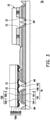
- FIG. 1 is a schematic partial cross-sectional view of an electronic device according to the first embodiment of the disclosure.
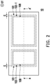
- FIG. 2 is a schematic partial top view of the electronic substrate in FIG. 1 .
- FIG. 2 uses a two-point chain line, a dashed line, and a one-point chain line to respectively mark the edges of the protruding portion, the first conductive layer, and the contact pad defining layer in FIG. 1 , and other elements and film layers are omitted.
- FIG. 1 for the cross-section of section line A-A' in FIG. 2 .
- an electronic device 1 may include a substrate 10 and an electronic element 12.
- the substrate 10 may be an electronic substrate.
- the electronic substrate (the substrate 10) may include a base 100, a protruding portion 101, and a bonding pad 102, but the disclosure is not limited thereto.
- the base 100 may be used to carry the protruding portion 101 and the bonding pad 102.
- the material of the base 100 may include glass, but the disclosure is not limited thereto.
- the base 100 may be a rigid base or a flexible base.
- the material of the base 100 may include glass, plastic, polycarbonate (PC), polyimide (PI), polyethylene terephthalate (PET), quartz, sapphire, ceramic, or a combination of the above. That is, the base 100 may be a single-layer board or a composite board, but the disclosure is not limited thereto.
- the protruding portion 101 is disposed on the base 100.
- the protruding portion 101 may be formed by a flat layer.
- the flat layer may be an organic insulating layer, but the disclosure is not limited thereto.
- the protruding portion 101 may be formed by a single-layer organic insulating layer.
- the protruding portion 101 may be formed by stacking a plurality of organic insulating layers.
- the protruding portion 101 may be an organic insulating layer, an inorganic insulating layer, or a combination thereof.
- the bonding pad 102 is disposed on the base 100 and may be used for bonding with the electronic element 12, but the disclosure is not limited thereto.
- the electronic element 12 may be an LED.
- the LED may include, for example, a mini LED, a micro LED, or a quantum dot LED (may include QLED or QDLED), but the disclosure is not limited thereto.
- the electronic element 12 may include a contact pad 120.
- the electronic device 1 may further include a conductive adhesive layer (such as a tin layer).
- the contact pad 120 may be soldered to the bonding pad 102 via a conductive adhesive layer 13 so that the electronic element 12 and the bonding pad 102 are electrically connected, but the disclosure is not limited thereto.
- the bonding pad 102 may include a two-layer stack structure.
- the bonding pad 102 may include a first conductive layer 102-1 and a second conductive layer 102-2 sequentially stacked on the base 100.
- the first conductive layer 102-1 and the second conductive layer 102-2 may be metal layers or metal alloy layers.
- the first conductive layer 102-1 may include a copper layer
- the second conductive layer 102-2 may include a nickel layer, but the disclosure is not limited thereto.
- the second conductive layer 102-2 may have a higher adhesive force with the conductive adhesive layer 13, so as to improve the adhesive force of the electronic element 12 to the bonding pad 102, but the disclosure is not limited thereto.
- the first conductive layer 102-1 and the second conductive layer 102-2 may have the same or different thicknesses.
- the bonding pad 102 may also be formed by a single conductive layer under suitable material selection.
- the bonding pad 102 is disposed on the base 100 after the protruding portion 101, for example.
- the electronic substrate 10 may further include an insulating layer (such as a fourth insulating layer 107).
- An insulating layer (such as the fourth insulating layer 107) is disposed on the protruding portion 101, and the bonding pad 102 may be disposed on the insulating layer (such as the fourth insulating layer 107).
- the position at which maximum stress occurs between the electronic element 12 and the base 100 may occur at a boundary B of the protruding portion 101 (that is, the boundary at which the protruding portion 101 starts to climb). That is, the base 100 is readily broken at the boundary B of the protruding portion 101, wherein the crack starts at the boundary B of the protruding portion 101 and ends in the base 100.
- the bonding pad 102 is not overlapped with the boundary B of the protruding portion 101, the bonding pad 102 is not overlapped with the position at which maximum stress may be generated (i.e., the boundary B of the protruding portion 101), in order to reduce the stress generated between the electronic element 12 and the base 100 or improve the flatness of a solder joint (for example, the flatness of the surface of the bonding pad 102 or the flatness of the surface of the copper layer), thus reducing the probability of the base 100 cracking or the electronic element 12 peeling off.
- the bonding pad 102 and the boundary B are not overlapped in a thickness direction DT of the electronic device 1.
- the gap G between the bonding pad 102 and the boundary B may fall within the range of 5 ⁇ m to 100 ⁇ m, that is, 5 ⁇ m ⁇ G ⁇ 100 ⁇ m, but the disclosure is not limited thereto.
- the gap G between the bonding pad 102 and the boundary B may be 0. That is, the bonding pad 102 and the boundary B may be aligned or substantially aligned.
- the gap G may fall in the range of 0 ⁇ m to 300 ⁇ m.
- the gap G may fall in the range of 0 ⁇ m to 200 ⁇ m. According to some embodiments, the gap G may be greater than zero. According to some embodiments, the gap G may fall in the range of 5 ⁇ m to 200 ⁇ m. According to some embodiments, the gap G may fall in the range of 5 ⁇ m to 100 ⁇ m. According to some embodiments, the gap G may fall in the range of 5 ⁇ m to 50 ⁇ m. According to some embodiments, the gap G may fall in the range of 5 ⁇ m to 10 ⁇ m. According to some embodiments, the gap G may be a gap between the first conductive layer 102-1 of the bonding pad 102 and the protruding portion 101. According to some embodiments, the gap G may be a gap between the second conductive layer 102-2 and the protruding portion 101.
- the bonding pad 102 when the bonding pad 102 is overlapped with the boundary B of the protruding portion 101 (not shown in the figures), specifically, a portion of the bonding pad 102 is overlapped with a portion of the protruding portion 101 in the thickness direction DT.
- the protruding portion 101 may have a slope at the edge.
- the bonding pad 102 is disposed on the boundary B of the protruding portion 101 and is formed along the slope of the protruding portion 101.
- the bonding pad 102 is formed along the slope of the protruding portion 101, the overlapping portion of the bonding pad 102 has an uneven surface, so that greater stress is readily generated between the electronic element 12 and the base 100, causing the base 100 to crack or the electronic element 12 to peel off.
- Base cracking rate refers to the ratio of the number of electronic elements peeled off or unable to operate normally due to base cracking to the total number of electronic elements on the same base. Whether an electronic element is peeled off or whether the electronic element may work normally (that is, whether the electronic element may be lit) may be observed by an optical microscope (OM). Taking glass as the base as an example, it may be seen according to the experimental results that, compared to a design in which the bonding pad and the boundary of the protruding portion are overlapped, in some embodiments, the design in which the bonding pad is not overlapped with the boundary of the protruding portion may reduce the base cracking rate from 11.5% to 2%.
- the design in which the bonding pad is not overlapped with the boundary of the protruding portion may reduce the maximum stress from 2905 MPa to 752 MPa. Therefore, in some embodiments, the design in which the bonding pad 102 is not overlapped with the boundary B of the protruding portion 101 helps to improve the reliability of the electronic device 1.
- the electronic substrate 10 may also include other elements or film layers.
- the electronic substrate 10 may further include a driving element 103, a first insulating layer 104, a second insulating layer 105, a third insulating layer 106, a fourth insulating layer 107, and a contact pad defining layer 108.
- the driving element 103 may be disposed on the base 100 and includes, for example, a gate (not shown), a channel layer CH, a source (not shown), and a drain DE.
- the driving element 103 may be, for example, a thin-film transistor, a top-gate thin-film transistor, or a bottom-gate thin-film transistor, but the disclosure is not limited thereto.
- the gate is disposed on the base 100.
- the material of the gate may include metal, alloy, or a combination thereof, but the disclosure is not limited thereto.
- the first insulating layer 104 is disposed on the gate and the base 100.
- the first insulating layer 104 may include an inorganic insulating layer, such as silicon oxide (SiOx) or silicon nitride (SiNx), but the disclosure is not limited thereto.
- the channel layer CH is disposed on the first insulating layer 104 and located above the gate.
- the material of the channel layer CH may include amorphous silicon, polysilicon, or metal oxide, but the disclosure is not limited thereto.
- the second insulating layer 105 is disposed on the channel layer CH and the first insulating layer 104.
- the second insulating layer 105 may include an inorganic insulating layer, such as silicon oxide (SiOx) or silicon nitride (SiNx), but the disclosure is not limited thereto.
- the second insulating layer 105 has an opening A1.
- the opening A1 exposes a portion of the channel layer CH.
- the source and the drain DE are disposed on the second insulating layer 105 and in contact with the channel layer CH via different openings A1.
- the material of the source and the drain DE may include metal, alloy, or a combination thereof, but the disclosure is not limited thereto.
- the third insulating layer 106 is disposed on the second insulating layer 105 and the source and the drain DE.
- the third insulating layer 106 may include an inorganic insulating layer, such as silicon oxide (SiOx) or silicon nitride (SiNx), but the disclosure is not limited thereto.
- the third insulating layer 106 has an opening A2.
- the opening A2 exposes a portion of the drain DE.
- the protruding portion 101 is disposed on the third insulating layer 106.
- the fourth insulating layer 107 is disposed on the protruding portion 101 and the third insulating layer 106.
- the fourth insulating layer 107 may include an inorganic insulating layer, such as silicon oxide (SiOx) or silicon nitride (SiNx), but the disclosure is not limited thereto.
- the fourth insulating layer 107 has an opening A3.
- the opening A3 and the opening A2 may be connected and expose a portion of the drain DE.
- the bonding pad 102 may include the first conductive layer 102-1 and the second conductive layer 102-2.
- the first conductive layer 102-1 may be disposed on the fourth insulating layer 107, wherein the first conductive layer 102-1 of at least one bonding pad 102 may be in contact with the drain DE via the opening A2 and the opening A3.
- the contact pad defining layer 108 is disposed on the fourth insulating layer 107 and covers a portion E102-1 of the first conductive layer 102-1 of each of the bonding pads 102.
- the second conductive layer 102-2 may be disposed on the first conductive layer 102-1 and may cover a portion E108 of the pad defining layer 108. According to some embodiments, as shown in FIG.
- an edge E1 of the first conductive layer 102-1 may be closer to the boundary B of the protruding portion 101 than an edge E2 of the second conductive layer 102-2.
- a portion of the pad defining layer 108 may cover a portion of the first conductive layer 102-1, such as the portion E102-1.
- the edge E1 of the first conductive layer 102-1 may be farther from the boundary B of the protruding portion 101 than the edge E2 of the second conductive layer 102-2.
- FIG. 1 shows one electronic element 12, any number of the electronic element 12 may be disposed on the electronic substrate 10 as needed.
- the type of the electronic element 12 may be changed as needed, and is not limited to an LED.
- the electronic device 1 may be, for example, a light-emitting device, a display device (such as a non-self-light-emitting display device), or a tiled display device, but the disclosure is not limited thereto.
- FIG. 3 is a schematic partial cross-sectional view of an electronic device according to the second embodiment of the disclosure. Please refer to FIG. 3 , the main differences between an electronic device 1A and the electronic device 1 in FIG. 1 are described as follows.
- the electronic device 1A includes an electronic substrate 10A, the electronic element 12, the conductive adhesive layer 13, and a circuit board 14.
- the electronic substrate 10A may be, for example, a chip integrated with an active element (such as a thin-film transistor) and a passive element (such as a capacitor or a resistor).
- the electronic substrate 10A may include a driving circuit, but the disclosure is not limited thereto.
- FIG. 3 schematically shows that the electronic substrate 10A has a similar structure to the electronic substrate 10 in FIG.
- FIG. 3 omits drawing some of the film layers and elements of the electronic substrate 10A. Please refer to FIG. 1 for the omitted film layers and elements.
- the electronic substrate 10A and the electronic element 12 are bonded onto the same side of the circuit board 14, and the electronic substrate 10A and the electronic element 12 are electrically connected via the circuit board 14.
- the circuit board 14 may include a circuit substrate 140, a bonding pad 141, and a protective layer 142.
- the circuit substrate 140 may include a plurality of metal layers (not shown) and a plurality of insulating layers (not shown) stacked alternately.
- the bonding pad 141 is disposed on the circuit substrate 140 and may be used for bonding with the electronic element 12 and the electronic substrate 10A, but the disclosure is not limited thereto.
- the contact pad 120 of the electronic element 12 and the bonding pad 102 of the electronic substrate 10A may be soldered to the bonding pad 141 via the conductive adhesive layer 13 (such as a tin layer), so that the electronic element 12 and the bonding pad 102 are electrically connected, but the disclosure is not limited thereto.
- the bonding pad 141 may include a two-layer stack structure.
- the bonding pad 141 may include a first conductive layer 141-1 (for example, a copper layer) and a second conductive layer 141-2 (for example, a nickel layer) sequentially stacked on the circuit substrate 140, wherein compared with the first conductive layer 141-1, the second conductive layer 141-2 may have a higher adhesive force with the conductive adhesive layer 13, so as to improve the adhesive force of the electronic element 12 and the electronic substrate 10A to the bonding pad 141, but the disclosure is not limited thereto.
- the bonding pad 141 may also be formed by a single conductive layer under suitable material selection.
- the protective layer 142 is disposed on the circuit substrate 140 and a portion of the first conductive layer 141-1.
- the protective layer 142 has a plurality of openings A4.
- the plurality of openings A4 respectively expose the area of the first conductive layer 141-1 at which the second conductive layer 141-2 is to be disposed, so that the second conductive layer 141-2 is disposed on the first conductive layer 141-1.
- the material of the protective layer 142 may include a solder resist or a photoresist, but the disclosure is not limited thereto.
- the reliability of the electronic device 1A may also be improved via a design in which the bonding pad 102 is not overlapped with the boundary of the protruding portion 101. Please refer to the above for specific description, which is not repeated herein.
- FIG. 3 only shows one electronic element 12 and one electronic substrate 10A
- any number of the electronic element 12 and any number of the electronic substrate 10A may be disposed on the circuit board 14 as needed.
- the type of the electronic element 12 may be changed as needed, and is not limited to an LED.
- the specific structure of the electronic substrate 10A may also be changed as needed, and is not limited to that shown in FIG. 3 .
- the electronic device 1A may be, for example, a display device (such as a non-self-light-emitting display device), or a tiled display device, but the disclosure is not limited thereto.
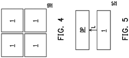
- FIG. 4 is a schematic partial top view of an electronic device according to the third embodiment of the disclosure.
- an electronic device 1B is, for example, a tiled display device.
- the electronic device 1B may be formed by tiling four of the electronic device 1 as shown in FIG. 1 , but the number of the electronic device 1 in the electronic device 1B may be changed as needed.
- each of the electronic devices 1 includes, for example, one electronic substrate 10 (refer to FIG. 1 ), the four electronic devices 1 include four electronic substrates 10, and the four electronic substrates 10 are tiled together to form a tiled display device.
- the electronic device 1B may also be formed by tiling a plurality of the electronic device 1A shown in FIG. 3 .
- FIG. 5 is a schematic partial cross-sectional view of an electronic device according to the fourth embodiment of the disclosure.
- an electronic device 1C is, for example, a non-self-light-emitting display device.
- the electronic device 1C may include the electronic device 1 shown in FIG. 1 and a display panel DP.
- the electronic device 1 is used as a backlight module, for example.
- the electronic element 12 in the electronic device 1 is, for example, an LED, and the display panel DP is disposed on the transmission path of a light beam L from the LED.
- the electronic device 1 in the electronic device 1C may also be replaced with the electronic device 1A in FIG. 3 .
- the stress generated between the electronic element and the base may be reduced or the flatness of the solder joint may be improved. Therefore, the probability of base cracking or electronic element peeling is reduced, thereby helping to improve the reliability of the electronic device.
Landscapes
- Engineering & Computer Science (AREA)
- Microelectronics & Electronic Packaging (AREA)
- Electroluminescent Light Sources (AREA)
- Devices For Indicating Variable Information By Combining Individual Elements (AREA)
Abstract
Description
- The disclosure relates to an electronic substrate and an electronic device including the electronic substrate.
- Electronic substrates and/or electronic devices need to pass a series of reliability tests before leaving the factory. In particular, when a base welded with a light-emitting diode (LED) is subjected to a thermal shock test, coefficient of thermal expansion (CTE) mismatch readily occurs between the LED and the base (such as glass), thus leading to cracks in the base or peeling of the LED and resulting in the generation of dark spots.
- The disclosure provides an electronic substrate and an electronic device that help to improve reliability.
- According to an embodiment of the disclosure, an electronic substrate includes a base, a protruding portion, and a bonding pad. The protruding portion and the bonding pad are disposed on the base. The bonding pad is not overlapped with a boundary of the protruding portion.
- According to another embodiment of the disclosure, an electronic device includes an electronic substrate and an electronic element. The electronic element is electrically connected to a bonding pad.
- In order to make the above features and advantages of the disclosure better understood, embodiments are specifically provided below with reference to figures for detailed description as follows.
- The accompanying drawings are included to provide a further understanding of the invention, and are incorporated in and constitute a part of this specification. The drawings illustrate embodiments of the invention and, together with the description, serve to explain the principles of the invention.
-
FIG. 1 is a schematic partial cross-sectional view of an electronic device according to the first embodiment of the disclosure. -
FIG. 2 is a schematic partial top view of the electronic substrate inFIG. 1 . -
FIG. 3 is a schematic partial cross-sectional view of an electronic device according to the second embodiment of the disclosure. -
FIG. 4 is a schematic partial top view of an electronic device according to the third embodiment of the disclosure. -
FIG. 5 is a schematic partial cross-sectional view of an electronic device according to the fourth embodiment of the disclosure. - The disclosure may be understood by referring to the following detailed description in conjunction with the accompanying figures. It should be noted that, in order to facilitate the reader's understanding and the simplicity of the figures, the multiple figures in the disclosure show a portion of the electronic device/display device, and the specific elements in the figures are not drawn according to actual scale. In addition, the number and size of each element in the figures are for illustration, and are not used to limit the scope of the disclosure. For example, the relative size, thickness, and location of film layers, regions, or structures may be reduced or enlarged for clarity.
- Throughout the disclosure, certain words are used to refer to specific elements in the specification and the claims. Those skilled in the art should understand that electronic equipment manufacturers may refer to the same elements by different names. The present specification does not intend to distinguish between elements that have the same function but different names. In the following description and claims, the words "have" and "include" and the like are open-ended words, and therefore should be interpreted as "including but not limited to..."
- In the present specification, wordings used to indicate direction, such as "up," "down," "front," "back," "left," and "right", merely refer to directions in the figures. Therefore, the directional terms are used to illustrate and are not intended to limit the disclosure. It should be understood that, when an element or film layer is said to be disposed "on" or "connected" to another element or film layer, the element or film layer may be directly on the other element or film layer or directly connected to the other element or film layer, or there may be an intervening element or film layer between the two (indirect case). Conversely, when an element or film layer is said to be "directly" on or "directly connected" to another element or film layer, there is no intervening element or film layer between the two.
- The terms "about", "equal to", "equal", "same", "substantially", or "essentially" mentioned in the present specification usually represent falling within 10% of a given value or range, or means falling within 5%, 3%, 2%, 1%, or 0.5% of a given value or range. In addition, the phrases "the given range is from a first value to a second value" and "the given range falls within the range of a first value to a second value" mean the given range includes the first value, the second value, and other values in between.
- In some embodiments of the disclosure, terms such as "connection", "interconnection", etc. regarding bonding and connection, unless specifically defined, may mean that two structures are in direct contact, or that two structures are not in direct contact, wherein there are other structures located between these two structures. Terms related to bonding and connection may also include the case in which both structures are movable or both structures are fixed. In addition, the terms "electrically connected" and "coupled" include any direct and indirect electrical connection means.
- In the following embodiments, the same or similar elements are designated by the same or similar reference numerals, and description thereof is omitted. Moreover, the features in different embodiments may be mixed and matched arbitrarily as long as they do not violate the spirit of the invention or conflict with each other. In addition, simple equivalent changes and modifications made in accordance with the present specification or claims are still within the scope of the disclosure. Moreover, terms such as "first" and "second" as used in this specification or the claims are used to identify different elements or to distinguish different embodiments or ranges, and are not intended to limit the upper limit or the lower limit of the number of elements and are also not intended to limit the order of manufacture of the elements or the order in which the elements are arranged.
- An electronic device of the disclosure may include, but is not limited to, a display device, an antenna device, a sensing device, a light-emitting device, or a tiling device. The electronic device may include a bendable or flexible electronic device. The electronic device may, for example, include a liquid crystal layer or a light-emitting diode. The light-emitting diode may include, for example, an organic light-emitting diode (OLED), a mini LED, a micro LED, or a quantum dot LED (may include QLED or QDLED), fluorescence, phosphor, or other suitable materials, or a combination of the above, but the disclosure is not limited thereto. Hereinafter, a display device is used as the electronic device to explain the disclosure, but the disclosure is not limited thereto.
- The display device of the disclosure may be any type of display device, such as a self-light-emitting display device or a non-self-light-emitting display device. The self-light-emitting display device may include an LED, a light conversion layer, or other suitable materials, or a combination of the above, but the disclosure is not limited thereto. The LED may include, for example, an organic light-emitting diode (OLED), a mini LED, a micro LED, or a quantum dot LED (may include QLED or QDLED), but the disclosure is not limited thereto. The light conversion layer may include a wavelength conversion material and/or a light filter material, and the light conversion layer may include, for example, fluorescence, phosphor, quantum dot (QD), other suitable materials, or a combination of the above, but the disclosure is not limited thereto. The non-self-light-emitting display device may include a liquid crystal display device, but the disclosure is not limited thereto.
-
FIG. 1 is a schematic partial cross-sectional view of an electronic device according to the first embodiment of the disclosure.FIG. 2 is a schematic partial top view of the electronic substrate inFIG. 1 . To simplify the illustration,FIG. 2 uses a two-point chain line, a dashed line, and a one-point chain line to respectively mark the edges of the protruding portion, the first conductive layer, and the contact pad defining layer inFIG. 1 , and other elements and film layers are omitted. Refer toFIG. 1 for the cross-section of section line A-A' inFIG. 2 . - Referring to
FIG. 1 andFIG. 2 , anelectronic device 1 may include asubstrate 10 and anelectronic element 12. For example, thesubstrate 10 may be an electronic substrate. The electronic substrate (the substrate 10) may include abase 100, aprotruding portion 101, and abonding pad 102, but the disclosure is not limited thereto. - The
base 100 may be used to carry theprotruding portion 101 and thebonding pad 102. For example, the material of thebase 100 may include glass, but the disclosure is not limited thereto. In some embodiments, thebase 100 may be a rigid base or a flexible base. In some embodiments, the material of thebase 100 may include glass, plastic, polycarbonate (PC), polyimide (PI), polyethylene terephthalate (PET), quartz, sapphire, ceramic, or a combination of the above. That is, thebase 100 may be a single-layer board or a composite board, but the disclosure is not limited thereto. - The protruding
portion 101 is disposed on thebase 100. For example, the protrudingportion 101 may be formed by a flat layer. In some embodiments, the flat layer may be an organic insulating layer, but the disclosure is not limited thereto. In some embodiments, the protrudingportion 101 may be formed by a single-layer organic insulating layer. In some other embodiments, the protrudingportion 101 may be formed by stacking a plurality of organic insulating layers. In some embodiments, the protrudingportion 101 may be an organic insulating layer, an inorganic insulating layer, or a combination thereof. - The
bonding pad 102 is disposed on thebase 100 and may be used for bonding with theelectronic element 12, but the disclosure is not limited thereto. For example, theelectronic element 12 may be an LED. The LED may include, for example, a mini LED, a micro LED, or a quantum dot LED (may include QLED or QDLED), but the disclosure is not limited thereto. In addition, theelectronic element 12 may include acontact pad 120. In some embodiments, theelectronic device 1 may further include a conductive adhesive layer (such as a tin layer). - The
contact pad 120 may be soldered to thebonding pad 102 via a conductiveadhesive layer 13 so that theelectronic element 12 and thebonding pad 102 are electrically connected, but the disclosure is not limited thereto. In some embodiments, thebonding pad 102 may include a two-layer stack structure. For example, thebonding pad 102 may include a first conductive layer 102-1 and a second conductive layer 102-2 sequentially stacked on thebase 100. The first conductive layer 102-1 and the second conductive layer 102-2 may be metal layers or metal alloy layers. Specifically, the first conductive layer 102-1 may include a copper layer, and the second conductive layer 102-2 may include a nickel layer, but the disclosure is not limited thereto. Compared with the first conductive layer 102-1, the second conductive layer 102-2 may have a higher adhesive force with the conductiveadhesive layer 13, so as to improve the adhesive force of theelectronic element 12 to thebonding pad 102, but the disclosure is not limited thereto. The first conductive layer 102-1 and the second conductive layer 102-2 may have the same or different thicknesses. In other embodiments, thebonding pad 102 may also be formed by a single conductive layer under suitable material selection. - In some embodiments, the
bonding pad 102 is disposed on the base 100 after the protrudingportion 101, for example. For example, theelectronic substrate 10 may further include an insulating layer (such as a fourth insulating layer 107). An insulating layer (such as the fourth insulating layer 107) is disposed on the protrudingportion 101, and thebonding pad 102 may be disposed on the insulating layer (such as the fourth insulating layer 107). - Due to the mismatch of the thermal expansion coefficients between the
electronic element 12 and thebase 100, when theelectronic device 1 is subjected to a thermal shock test, stress may be generated between theelectronic element 12 and thebase 100 due to thermal expansion and contraction. In the case of an uneven solder joint, such as the uneven surface of the bonding pad 102 (for example, an uneven surface of the copper layer), greater stress is likely to be generated between theelectronic element 12 and thebase 100, causing the base 100 to crack or theelectronic element 12 to peel off. - Based on observations, the position at which maximum stress occurs between the
electronic element 12 and the base 100 may occur at a boundary B of the protruding portion 101 (that is, the boundary at which the protrudingportion 101 starts to climb). That is, thebase 100 is readily broken at the boundary B of the protrudingportion 101, wherein the crack starts at the boundary B of the protrudingportion 101 and ends in thebase 100. - In an embodiment of the disclosure, since the
bonding pad 102 is not overlapped with the boundary B of the protrudingportion 101, thebonding pad 102 is not overlapped with the position at which maximum stress may be generated (i.e., the boundary B of the protruding portion 101), in order to reduce the stress generated between theelectronic element 12 and the base 100 or improve the flatness of a solder joint (for example, the flatness of the surface of thebonding pad 102 or the flatness of the surface of the copper layer), thus reducing the probability of the base 100 cracking or theelectronic element 12 peeling off. According to some embodiments, there is a gap G at thebonding pad 102 and the boundary B of the protrudingportion 101. For example, thebonding pad 102 and the boundary B are not overlapped in a thickness direction DT of theelectronic device 1. In some embodiments, considering the current process accuracy (such as exposure accuracy) and the small size requirements of theelectronic device 1, the gap G between thebonding pad 102 and the boundary B may fall within the range of 5 µm to 100 µm, that is, 5 µm ≦ G ≦ 100 µm, but the disclosure is not limited thereto. In other embodiments, the gap G between thebonding pad 102 and the boundary B may be 0. That is, thebonding pad 102 and the boundary B may be aligned or substantially aligned. According to some embodiments, the gap G may fall in the range of 0 µm to 300 µm. According to some embodiments, the gap G may fall in the range of 0 µm to 200 µm. According to some embodiments, the gap G may be greater than zero. According to some embodiments, the gap G may fall in the range of 5 µm to 200 µm. According to some embodiments, the gap G may fall in the range of 5 µm to 100 µm. According to some embodiments, the gap G may fall in the range of 5 µm to 50 µm. According to some embodiments, the gap G may fall in the range of 5 µm to 10 µm. According to some embodiments, the gap G may be a gap between the first conductive layer 102-1 of thebonding pad 102 and the protrudingportion 101. According to some embodiments, the gap G may be a gap between the second conductive layer 102-2 and the protrudingportion 101. - In contrast, when the
bonding pad 102 is overlapped with the boundary B of the protruding portion 101 (not shown in the figures), specifically, a portion of thebonding pad 102 is overlapped with a portion of the protrudingportion 101 in the thickness direction DT. As shown inFIG. 1 , the protrudingportion 101 may have a slope at the edge. For example, thebonding pad 102 is disposed on the boundary B of the protrudingportion 101 and is formed along the slope of the protrudingportion 101. Therefore, because thebonding pad 102 is formed along the slope of the protrudingportion 101, the overlapping portion of thebonding pad 102 has an uneven surface, so that greater stress is readily generated between theelectronic element 12 and thebase 100, causing the base 100 to crack or theelectronic element 12 to peel off. - Base cracking rate refers to the ratio of the number of electronic elements peeled off or unable to operate normally due to base cracking to the total number of electronic elements on the same base. Whether an electronic element is peeled off or whether the electronic element may work normally (that is, whether the electronic element may be lit) may be observed by an optical microscope (OM). Taking glass as the base as an example, it may be seen according to the experimental results that, compared to a design in which the bonding pad and the boundary of the protruding portion are overlapped, in some embodiments, the design in which the bonding pad is not overlapped with the boundary of the protruding portion may reduce the base cracking rate from 11.5% to 2%. Moreover, it may be known according to the simulation results that, compared to a design in which the bonding pad and the boundary of the protruding portion are overlapped, in some embodiments, the design in which the bonding pad is not overlapped with the boundary of the protruding portion may reduce the maximum stress from 2905 MPa to 752 MPa. Therefore, in some embodiments, the design in which the
bonding pad 102 is not overlapped with the boundary B of the protrudingportion 101 helps to improve the reliability of theelectronic device 1. - According to different requirements, as shown in
FIG. 1 , theelectronic substrate 10 may also include other elements or film layers. For example, theelectronic substrate 10 may further include a drivingelement 103, a first insulatinglayer 104, a second insulatinglayer 105, a thirdinsulating layer 106, a fourth insulatinglayer 107, and a contactpad defining layer 108. - Referring to
FIG. 1 , the drivingelement 103 may be disposed on thebase 100 and includes, for example, a gate (not shown), a channel layer CH, a source (not shown), and a drain DE. The drivingelement 103 may be, for example, a thin-film transistor, a top-gate thin-film transistor, or a bottom-gate thin-film transistor, but the disclosure is not limited thereto. Taking the drivingelement 103 as a bottom-gate thin-film transistor as an example, the gate is disposed on thebase 100. The material of the gate may include metal, alloy, or a combination thereof, but the disclosure is not limited thereto. The first insulatinglayer 104 is disposed on the gate and thebase 100. The first insulatinglayer 104 may include an inorganic insulating layer, such as silicon oxide (SiOx) or silicon nitride (SiNx), but the disclosure is not limited thereto. The channel layer CH is disposed on the first insulatinglayer 104 and located above the gate. The material of the channel layer CH may include amorphous silicon, polysilicon, or metal oxide, but the disclosure is not limited thereto. The secondinsulating layer 105 is disposed on the channel layer CH and the first insulatinglayer 104. The secondinsulating layer 105 may include an inorganic insulating layer, such as silicon oxide (SiOx) or silicon nitride (SiNx), but the disclosure is not limited thereto. The secondinsulating layer 105 has an opening A1. The opening A1 exposes a portion of the channel layer CH. The source and the drain DE are disposed on the second insulatinglayer 105 and in contact with the channel layer CH via different openings A1. The material of the source and the drain DE may include metal, alloy, or a combination thereof, but the disclosure is not limited thereto. The thirdinsulating layer 106 is disposed on the second insulatinglayer 105 and the source and the drain DE. The thirdinsulating layer 106 may include an inorganic insulating layer, such as silicon oxide (SiOx) or silicon nitride (SiNx), but the disclosure is not limited thereto. The thirdinsulating layer 106 has an opening A2. The opening A2 exposes a portion of the drain DE. The protrudingportion 101 is disposed on the third insulatinglayer 106. The fourth insulatinglayer 107 is disposed on the protrudingportion 101 and the third insulatinglayer 106. The fourth insulatinglayer 107 may include an inorganic insulating layer, such as silicon oxide (SiOx) or silicon nitride (SiNx), but the disclosure is not limited thereto. The fourth insulatinglayer 107 has an opening A3. The opening A3 and the opening A2 may be connected and expose a portion of the drain DE. - Referring further to
FIG. 1 , thebonding pad 102 may include the first conductive layer 102-1 and the second conductive layer 102-2. The first conductive layer 102-1 may be disposed on the fourth insulatinglayer 107, wherein the first conductive layer 102-1 of at least onebonding pad 102 may be in contact with the drain DE via the opening A2 and the opening A3. The contactpad defining layer 108 is disposed on the fourth insulatinglayer 107 and covers a portion E102-1 of the first conductive layer 102-1 of each of thebonding pads 102. The second conductive layer 102-2 may be disposed on the first conductive layer 102-1 and may cover a portion E108 of thepad defining layer 108. According to some embodiments, as shown inFIG. 1 , for the same side of theelectronic element 12, an edge E1 of the first conductive layer 102-1 may be closer to the boundary B of the protrudingportion 101 than an edge E2 of the second conductive layer 102-2. In this way, a portion of thepad defining layer 108 may cover a portion of the first conductive layer 102-1, such as the portion E102-1. According to some embodiments (not shown in the figures), for the same side of theelectronic element 12, the edge E1 of the first conductive layer 102-1 may be farther from the boundary B of the protrudingportion 101 than the edge E2 of the second conductive layer 102-2. - It should be understood that although
FIG. 1 shows oneelectronic element 12, any number of theelectronic element 12 may be disposed on theelectronic substrate 10 as needed. In addition, the type of theelectronic element 12 may be changed as needed, and is not limited to an LED. Under the architecture in which theelectronic element 12 is an LED, theelectronic device 1 may be, for example, a light-emitting device, a display device (such as a non-self-light-emitting display device), or a tiled display device, but the disclosure is not limited thereto. -
FIG. 3 is a schematic partial cross-sectional view of an electronic device according to the second embodiment of the disclosure. Please refer toFIG. 3 , the main differences between anelectronic device 1A and theelectronic device 1 inFIG. 1 are described as follows. Theelectronic device 1A includes an electronic substrate 10A, theelectronic element 12, the conductiveadhesive layer 13, and acircuit board 14. The electronic substrate 10A may be, for example, a chip integrated with an active element (such as a thin-film transistor) and a passive element (such as a capacitor or a resistor). For example, the electronic substrate 10A may include a driving circuit, but the disclosure is not limited thereto.FIG. 3 schematically shows that the electronic substrate 10A has a similar structure to theelectronic substrate 10 inFIG. 1 , with the difference that the electronic substrate 10A further includes a circuit layer 109 disposed between the base 100 and the third insulatinglayer 106. In order to clearly show the circuit layer 109,FIG. 3 omits drawing some of the film layers and elements of the electronic substrate 10A. Please refer toFIG. 1 for the omitted film layers and elements. - The electronic substrate 10A and the
electronic element 12 are bonded onto the same side of thecircuit board 14, and the electronic substrate 10A and theelectronic element 12 are electrically connected via thecircuit board 14. For example, thecircuit board 14 may include acircuit substrate 140, abonding pad 141, and aprotective layer 142. - The
circuit substrate 140 may include a plurality of metal layers (not shown) and a plurality of insulating layers (not shown) stacked alternately. Thebonding pad 141 is disposed on thecircuit substrate 140 and may be used for bonding with theelectronic element 12 and the electronic substrate 10A, but the disclosure is not limited thereto. For example, thecontact pad 120 of theelectronic element 12 and thebonding pad 102 of the electronic substrate 10A may be soldered to thebonding pad 141 via the conductive adhesive layer 13 (such as a tin layer), so that theelectronic element 12 and thebonding pad 102 are electrically connected, but the disclosure is not limited thereto. In some embodiments, thebonding pad 141 may include a two-layer stack structure. For example, thebonding pad 141 may include a first conductive layer 141-1 (for example, a copper layer) and a second conductive layer 141-2 (for example, a nickel layer) sequentially stacked on thecircuit substrate 140, wherein compared with the first conductive layer 141-1, the second conductive layer 141-2 may have a higher adhesive force with the conductiveadhesive layer 13, so as to improve the adhesive force of theelectronic element 12 and the electronic substrate 10A to thebonding pad 141, but the disclosure is not limited thereto. In other embodiments, thebonding pad 141 may also be formed by a single conductive layer under suitable material selection. - The
protective layer 142 is disposed on thecircuit substrate 140 and a portion of the first conductive layer 141-1. In detail, theprotective layer 142 has a plurality of openings A4. The plurality of openings A4 respectively expose the area of the first conductive layer 141-1 at which the second conductive layer 141-2 is to be disposed, so that the second conductive layer 141-2 is disposed on the first conductive layer 141-1. The material of theprotective layer 142 may include a solder resist or a photoresist, but the disclosure is not limited thereto. - In the present embodiment, the reliability of the
electronic device 1A may also be improved via a design in which thebonding pad 102 is not overlapped with the boundary of the protrudingportion 101. Please refer to the above for specific description, which is not repeated herein. - It should be understood that, although
FIG. 3 only shows oneelectronic element 12 and one electronic substrate 10A, any number of theelectronic element 12 and any number of the electronic substrate 10A may be disposed on thecircuit board 14 as needed. In addition, the type of theelectronic element 12 may be changed as needed, and is not limited to an LED. In addition, the specific structure of the electronic substrate 10A may also be changed as needed, and is not limited to that shown inFIG. 3 . Under the architecture in which theelectronic element 12 is an LED, theelectronic device 1A may be, for example, a display device (such as a non-self-light-emitting display device), or a tiled display device, but the disclosure is not limited thereto. -
FIG. 4 is a schematic partial top view of an electronic device according to the third embodiment of the disclosure. Please refer toFIG. 4 , anelectronic device 1B is, for example, a tiled display device. For example, theelectronic device 1B may be formed by tiling four of theelectronic device 1 as shown inFIG. 1 , but the number of theelectronic device 1 in theelectronic device 1B may be changed as needed. InFIG. 4 , each of theelectronic devices 1 includes, for example, one electronic substrate 10 (refer toFIG. 1 ), the fourelectronic devices 1 include fourelectronic substrates 10, and the fourelectronic substrates 10 are tiled together to form a tiled display device. In other embodiments, in the case that the electronic substrate 10A inFIG. 3 does not affect display quality, for example, when the size of the electronic substrate 10A is much smaller than the size of theelectronic device 1B, or the size of the electronic substrate 10A is very small, theelectronic device 1B may also be formed by tiling a plurality of theelectronic device 1A shown inFIG. 3 . -
FIG. 5 is a schematic partial cross-sectional view of an electronic device according to the fourth embodiment of the disclosure. Please refer toFIG. 5 , anelectronic device 1C is, for example, a non-self-light-emitting display device. For example, theelectronic device 1C may include theelectronic device 1 shown inFIG. 1 and a display panel DP. In theelectronic device 1C, theelectronic device 1 is used as a backlight module, for example. Theelectronic element 12 in theelectronic device 1 is, for example, an LED, and the display panel DP is disposed on the transmission path of a light beam L from the LED. In other embodiments, theelectronic device 1 in theelectronic device 1C may also be replaced with theelectronic device 1A inFIG. 3 . - Based on the above, in an embodiment of the disclosure, via the design that the bonding pad is not overlapped with the boundary of the protruding portion, the stress generated between the electronic element and the base may be reduced or the flatness of the solder joint may be improved. Therefore, the probability of base cracking or electronic element peeling is reduced, thereby helping to improve the reliability of the electronic device.
Claims (15)
- An electronic substrate (10, 10A), comprising:a base (100);a protruding portion (101) disposed on the base (100); anda bonding pad (102, 141) disposed on the base (100);wherein the bonding pad (102, 141) is not overlapped with a boundary (B) of the protruding portion (101).
- The electronic substrate (10, 10A) of claim 1, wherein a gap (G) between the bonding pad (102, 141) and the boundary (B) falls within a range of 5 µm to 100 µm.
- The electronic substrate (10, 10A) of claim 1, wherein the protruding portion (101) is formed by a flat layer.
- The electronic substrate (10, 10A) of claim 3, wherein the flat layer is an organic insulating layer.
- The electronic substrate (10, 10A) of claim 3, further comprising:an insulating layer (104, 105, 106, 107) disposed on the protruding portion (101),wherein the bonding pad (102, 141) is disposed on the insulating layer (104, 105, 106, 107).
- The electronic substrate (10, 10A) of claim 5, wherein the bonding pad (102, 141) comprises:a first conductive layer (102-1, 141-1) disposed on the insulating layer (104, 105, 106, 107); anda second conductive layer (102-2, 141-2) disposed on the first conductive layer (102-1, 141-1), wherein the second conductive layer (102-2, 141-2) exposes an edge portion of the first conductive layer (102-1, 141-1).
- The electronic substrate (10, 10A) of claim 6, further comprising:
a contact pad defining layer (108) disposed on the insulating layer (104, 105, 106, 107) and covering the edge portion of the first conductive layer (102-1, 141-1), and the second conductive layer (102-2, 141-2) is disposed on the first conductive layer (102-1, 141-1) and covers an edge portion of the contact pad defining layer (108). - An electronic device (1, 1A, 1B, 1C), comprising:an electronic substrate (10, 10A), comprising:a base (100);a protruding portion (101) disposed on the base (100); anda bonding pad (102, 141) disposed on the base (100), wherein the bonding pad (102, 141) is not overlapped with a boundary (B) of the protruding portion (101); andan electronic element (12) electrically connected to the bonding pad (102, 141) of the electronic substrate (10, 10A).
- The electronic device (1, 1A, 1B, 1C) of claim 8, wherein a gap (G) between the bonding pad (102, 141) and the boundary (B) falls within a range of 5 µm to 100 µm.
- The electronic device (1, 1A, 1B, 1C) of claim 8, wherein the protruding portion (101) is formed by a flat layer.
- The electronic device (1, 1A, 1B, 1C) of claim 10, wherein the flat layer is an organic insulating layer.
- The electronic device (1, 1A, 1B, 1C) of claim 10, wherein the electronic substrate (10, 10A) further comprises:an insulating layer (104, 105, 106, 107) disposed on the protruding portion (101),wherein the bonding pad (102, 141) is disposed on the insulating layer (104, 105, 106, 107).
- The electronic device (1, 1A, 1B, 1C) of claim 12, wherein the bonding pad (102, 141) comprises:a first conductive layer (102-1, 141-1) disposed on the insulating layer (104, 105, 106, 107); anda second conductive layer (102-2, 141-2) disposed on the first conductive layer (102-1, 141-1), wherein the second conductive layer (102-2, 141-2) exposes an edge portion of the first conductive layer (102-1, 141-1).
- The electronic device (1, 1A, 1B, 1C) of claim 13, wherein the electronic substrate (10, 10A) further comprises:
a contact pad defining layer (108) disposed on the insulating layer (104, 105, 106, 107) and covering the edge portion of the first conductive layer (102-1, 141-1), and the second conductive layer (102-2, 141-2) is disposed on the first conductive layer (102-1, 141-1) and covers an edge portion of the contact pad defining layer (108). - The electronic device (1, 1A, 1B, 1C) of claim 8, further comprising:
a conductive adhesive layer (13), wherein the electronic element (12) is electrically connected to the bonding pad (102, 141) of the electronic substrate (10, 10A) via the conductive adhesive layer (13).
Applications Claiming Priority (2)
| Application Number | Priority Date | Filing Date | Title |
|---|---|---|---|
| US202063055900P | 2020-07-24 | 2020-07-24 | |
| CN202110189431.7A CN113972308B (en) | 2020-07-24 | 2021-02-19 | Electronic substrate and electronic device |
Publications (1)
| Publication Number | Publication Date |
|---|---|
| EP3944347A1 true EP3944347A1 (en) | 2022-01-26 |
Family
ID=77179862
Family Applications (1)
| Application Number | Title | Priority Date | Filing Date |
|---|---|---|---|
| EP21185075.5A Pending EP3944347A1 (en) | 2020-07-24 | 2021-07-12 | Electronic substrate and electronic device |
Country Status (2)
| Country | Link |
|---|---|
| US (3) | US11830833B2 (en) |
| EP (1) | EP3944347A1 (en) |
Citations (3)
| Publication number | Priority date | Publication date | Assignee | Title |
|---|---|---|---|---|
| US20140077249A1 (en) * | 2007-07-25 | 2014-03-20 | Lg Innotek Co., Ltd | Light emitting device package and method of manufacturing the same |
| DE102013201952A1 (en) * | 2013-02-06 | 2014-08-21 | Osram Gmbh | Semiconductor light-emitting module has substrate whose front side is arranged with semiconductor light sources that are laterally surrounded with circumferential side wall |
| DE102015109367A1 (en) * | 2015-06-12 | 2016-12-15 | Osram Opto Semiconductors Gmbh | Optoelectronic lighting device |
Family Cites Families (24)
| Publication number | Priority date | Publication date | Assignee | Title |
|---|---|---|---|---|
| JPH10270496A (en) * | 1997-03-27 | 1998-10-09 | Hitachi Ltd | Electronic device, information processing device, semiconductor device, and semiconductor chip mounting method |
| KR100280553B1 (en) * | 1999-01-22 | 2001-01-15 | 김영환 | Semiconductor device and fabricationg method thereof |
| US6291264B1 (en) | 2000-07-31 | 2001-09-18 | Siliconware Precision Industries Co., Ltd. | Flip-chip package structure and method of fabricating the same |
| JP2002164480A (en) * | 2000-11-27 | 2002-06-07 | Dow Corning Toray Silicone Co Ltd | Electronic component coating method |
| US20070235217A1 (en) | 2006-03-29 | 2007-10-11 | Workman Derek B | Devices with microjetted polymer standoffs |
| US8513119B2 (en) | 2008-12-10 | 2013-08-20 | Taiwan Semiconductor Manufacturing Company, Ltd. | Method of forming bump structure having tapered sidewalls for stacked dies |
| KR101054440B1 (en) | 2009-04-27 | 2011-08-05 | 삼성전기주식회사 | Electronic device package and manufacturing method thereof |
| KR20120056051A (en) * | 2010-11-24 | 2012-06-01 | 삼성전자주식회사 | Method for manufacturing semiconductor package and the semiconductor package manufactured using the method |
| JP5801685B2 (en) | 2011-10-24 | 2015-10-28 | 新光電気工業株式会社 | WIRING BOARD, LIGHT EMITTING DEVICE, AND WIRING BOARD MANUFACTURING METHOD |
| US9159700B2 (en) | 2012-12-10 | 2015-10-13 | LuxVue Technology Corporation | Active matrix emissive micro LED display |
| KR101768254B1 (en) * | 2013-06-12 | 2017-08-16 | 매그나칩 반도체 유한회사 | Semiconductor-based magnetic sensor and method of manufacturing thereof |
| WO2015132698A1 (en) * | 2014-03-06 | 2015-09-11 | Semiconductor Energy Laboratory Co., Ltd. | Light-emitting device |
| TWI553880B (en) * | 2014-05-22 | 2016-10-11 | 群創光電股份有限公司 | Thin film transistor substrate, manufacturing method thereof and display |
| US9405089B2 (en) * | 2014-05-22 | 2016-08-02 | Texas Instruments Incorporated | High-temperature isotropic plasma etching process to prevent electrical shorts |
| US9543384B2 (en) * | 2015-02-26 | 2017-01-10 | SK Hynix Inc. | Semiconductor package |
| TWI551931B (en) * | 2015-03-23 | 2016-10-01 | 群創光電股份有限公司 | Display panel |
| TWI600946B (en) * | 2015-04-07 | 2017-10-01 | 群創光電股份有限公司 | Display panel |
| CN113219749B (en) * | 2016-02-17 | 2023-01-10 | 群创光电股份有限公司 | Active element array substrate and display panel |
| CN107564877A (en) * | 2016-06-30 | 2018-01-09 | 华邦电子股份有限公司 | Semiconductor device package and semiconductor device packaging process |
| US20180190575A1 (en) * | 2017-01-05 | 2018-07-05 | Stmicroelectronics, Inc. | Leadframe with lead protruding from the package |
| CN110391252A (en) | 2018-04-19 | 2019-10-29 | 群创光电股份有限公司 | Electronic device |
| US11422104B2 (en) * | 2019-09-06 | 2022-08-23 | Apple Inc. | Exposed wire-bonding for sensing liquid and water in electronic devices |
| CN110634840B (en) * | 2019-09-24 | 2021-08-20 | 京东方科技集团股份有限公司 | Detection substrate and preparation method thereof, detection device and detection method |
| US11101233B1 (en) * | 2020-05-07 | 2021-08-24 | Taiwan Semiconductor Manufacturing Co., Ltd. | Semiconductor device and method for forming the same |
-
2021
- 2021-06-30 US US17/363,018 patent/US11830833B2/en active Active
- 2021-07-12 EP EP21185075.5A patent/EP3944347A1/en active Pending
-
2023
- 2023-10-19 US US18/489,871 patent/US12362300B2/en active Active
-
2025
- 2025-06-26 US US19/250,073 patent/US20250323193A1/en active Pending
Patent Citations (3)
| Publication number | Priority date | Publication date | Assignee | Title |
|---|---|---|---|---|
| US20140077249A1 (en) * | 2007-07-25 | 2014-03-20 | Lg Innotek Co., Ltd | Light emitting device package and method of manufacturing the same |
| DE102013201952A1 (en) * | 2013-02-06 | 2014-08-21 | Osram Gmbh | Semiconductor light-emitting module has substrate whose front side is arranged with semiconductor light sources that are laterally surrounded with circumferential side wall |
| DE102015109367A1 (en) * | 2015-06-12 | 2016-12-15 | Osram Opto Semiconductors Gmbh | Optoelectronic lighting device |
Also Published As
| Publication number | Publication date |
|---|---|
| US20220028809A1 (en) | 2022-01-27 |
| US20250323193A1 (en) | 2025-10-16 |
| US12362300B2 (en) | 2025-07-15 |
| US11830833B2 (en) | 2023-11-28 |
| US20240047393A1 (en) | 2024-02-08 |
Similar Documents
| Publication | Publication Date | Title |
|---|---|---|
| CN107004617B (en) | Flexible display device with bridged wiring traces | |
| CN107799550A (en) | Flexible display | |
| US11011598B2 (en) | Spliced unit and spliced panel | |
| US12245494B2 (en) | Electronic device | |
| TWI855305B (en) | Electronic device | |
| CN113571494B (en) | Electronic device and method for manufacturing the same | |
| US12362300B2 (en) | Electronic substrate and electronic device | |
| US12543373B2 (en) | Electronic device including conductive layer disposed between substrate and electronic element | |
| TWI911535B (en) | Electronic device | |
| CN113972308B (en) | Electronic substrate and electronic device | |
| TWI850541B (en) | Semiconductor package | |
| CN118500451A (en) | Flexible sensor | |
| TWI917806B (en) | Flexible sensor | |
| CN112992918A (en) | Light emitting device | |
| US12453016B2 (en) | Electronic device | |
| US20260059664A1 (en) | Electronic device and manufacturing method thereof | |
| US20240130040A1 (en) | Conductive film and test component | |
| TWI920433B (en) | Electronic device and manufacturing method thereof | |
| US20240332474A1 (en) | Electronic device | |
| CN118366999A (en) | Electronic Devices | |
| CN119031581A (en) | Electronic device and spliced electronic device | |
| KR20230172418A (en) | Electronic device and manufacturing method thereof | |
| CN120129422A (en) | Electronic Devices | |
| CN119546028A (en) | Electronic Devices | |
| CN117410247A (en) | electronic device |
Legal Events
| Date | Code | Title | Description |
|---|---|---|---|
| PUAI | Public reference made under article 153(3) epc to a published international application that has entered the european phase |
Free format text: ORIGINAL CODE: 0009012 |
|
| STAA | Information on the status of an ep patent application or granted ep patent |
Free format text: STATUS: THE APPLICATION HAS BEEN PUBLISHED |
|
| AK | Designated contracting states |
Kind code of ref document: A1 Designated state(s): AL AT BE BG CH CY CZ DE DK EE ES FI FR GB GR HR HU IE IS IT LI LT LU LV MC MK MT NL NO PL PT RO RS SE SI SK SM TR |
|
| STAA | Information on the status of an ep patent application or granted ep patent |
Free format text: STATUS: REQUEST FOR EXAMINATION WAS MADE |
|
| 17P | Request for examination filed |
Effective date: 20220725 |
|
| RBV | Designated contracting states (corrected) |
Designated state(s): AL AT BE BG CH CY CZ DE DK EE ES FI FR GB GR HR HU IE IS IT LI LT LU LV MC MK MT NL NO PL PT RO RS SE SI SK SM TR |