EP3944285A1 - Ion milling apparatus and method of manufacturing sample - Google Patents
Ion milling apparatus and method of manufacturing sample Download PDFInfo
- Publication number
- EP3944285A1 EP3944285A1 EP21185017.7A EP21185017A EP3944285A1 EP 3944285 A1 EP3944285 A1 EP 3944285A1 EP 21185017 A EP21185017 A EP 21185017A EP 3944285 A1 EP3944285 A1 EP 3944285A1
- Authority
- EP
- European Patent Office
- Prior art keywords
- sample
- ion
- ion beam
- ion source
- shielding member
- Prior art date
- Legal status (The legal status is an assumption and is not a legal conclusion. Google has not performed a legal analysis and makes no representation as to the accuracy of the status listed.)
- Granted
Links
Images







Classifications
-
- H—ELECTRICITY
- H01—ELECTRIC ELEMENTS
- H01J—ELECTRIC DISCHARGE TUBES OR DISCHARGE LAMPS
- H01J37/00—Discharge tubes with provision for introducing objects or material to be exposed to the discharge, e.g. for the purpose of examination or processing thereof
- H01J37/02—Details
- H01J37/20—Means for supporting or positioning the object or the material; Means for adjusting diaphragms or lenses associated with the support
-
- H—ELECTRICITY
- H01—ELECTRIC ELEMENTS
- H01J—ELECTRIC DISCHARGE TUBES OR DISCHARGE LAMPS
- H01J37/00—Discharge tubes with provision for introducing objects or material to be exposed to the discharge, e.g. for the purpose of examination or processing thereof
- H01J37/02—Details
- H01J37/04—Arrangements of electrodes and associated parts for generating or controlling the discharge, e.g. electron-optical arrangement or ion-optical arrangement
- H01J37/09—Diaphragms; Shields associated with electron or ion-optical arrangements; Compensation of disturbing fields
-
- H—ELECTRICITY
- H01—ELECTRIC ELEMENTS
- H01J—ELECTRIC DISCHARGE TUBES OR DISCHARGE LAMPS
- H01J37/00—Discharge tubes with provision for introducing objects or material to be exposed to the discharge, e.g. for the purpose of examination or processing thereof
- H01J37/30—Electron-beam or ion-beam tubes for localised treatment of objects
- H01J37/305—Electron-beam or ion-beam tubes for localised treatment of objects for casting, melting, evaporating, or etching
- H01J37/3053—Electron-beam or ion-beam tubes for localised treatment of objects for casting, melting, evaporating, or etching for evaporating or etching
-
- H—ELECTRICITY
- H01—ELECTRIC ELEMENTS
- H01J—ELECTRIC DISCHARGE TUBES OR DISCHARGE LAMPS
- H01J37/00—Discharge tubes with provision for introducing objects or material to be exposed to the discharge, e.g. for the purpose of examination or processing thereof
- H01J37/30—Electron-beam or ion-beam tubes for localised treatment of objects
- H01J37/305—Electron-beam or ion-beam tubes for localised treatment of objects for casting, melting, evaporating, or etching
- H01J37/3053—Electron-beam or ion-beam tubes for localised treatment of objects for casting, melting, evaporating, or etching for evaporating or etching
- H01J37/3056—Electron-beam or ion-beam tubes for localised treatment of objects for casting, melting, evaporating, or etching for evaporating or etching for microworking, e. g. etching of gratings or trimming of electrical components
-
- H—ELECTRICITY
- H01—ELECTRIC ELEMENTS
- H01J—ELECTRIC DISCHARGE TUBES OR DISCHARGE LAMPS
- H01J2237/00—Discharge tubes exposing object to beam, e.g. for analysis treatment, etching, imaging
- H01J2237/20—Positioning, supporting, modifying or maintaining the physical state of objects being observed or treated
- H01J2237/202—Movement
- H01J2237/20214—Rotation
-
- H—ELECTRICITY
- H01—ELECTRIC ELEMENTS
- H01J—ELECTRIC DISCHARGE TUBES OR DISCHARGE LAMPS
- H01J2237/00—Discharge tubes exposing object to beam, e.g. for analysis treatment, etching, imaging
- H01J2237/30—Electron or ion beam tubes for processing objects
- H01J2237/317—Processing objects on a microscale
- H01J2237/3174—Etching microareas
- H01J2237/31745—Etching microareas for preparing specimen to be viewed in microscopes or analyzed in microanalysers
Definitions
- the present invention relates to an ion milling apparatus and a method of manufacturing a sample.
- An object of the present invention is to provide an ion milling apparatus and a method of manufacturing a sample that are capable of efficiently manufacturing a sample having a cross section whose inclination is reduced.
- FIG. 1 is a schematic diagram illustrating a configuration example of an ion milling apparatus 10 according to a first embodiment of the present invention.
- FIG. 2 is an enlarged diagram of a main part of the ion milling apparatus 10 according to the first embodiment of the present invention.
- the sample holder 27 includes a pair of shielding members 29 (29a and 29b) sandwiching the sample 11.
- the reason why the sample holder 27 is provided with the pair of shielding members 29 is to enable the sample 11 to be processed from either an upper side or a lower side.
- the ion milling apparatus 10 according to the first embodiment of the present invention has a configuration in which an orientation of the sample holder 27 supporting the sample 11 can be vertically inverted, or a configuration in which the attachment position of the ion source 17 in the vacuum chamber 15 can be vertically inverted.
- the shielding member 29 arranged on the upper side in FIG. 2 is referred to as a first shielding member 29a
- the shielding member 29 arranged on the lower side is referred to as a second shielding member 29b.
- the first shielding member 29a is fixed to a first holder body 28a by a screw 35.
- the second shielding member 29b is fixed to the second holder body 28b by a screw 36.
- the holder body 28 includes the first holder body 28a and the second holder body 28b.
- the rear end portion of each of the first holder body 28a and the second holder body 28b can be mounted on the sample stage 18 from either an up or down direction by, for example, a dovetail groove type coupling structure.
- the sample stage 18 is pushed into the vacuum chamber 15 by the sample stage pull-out mechanism 16, whereby the sample stage 18 is accommodated in the vacuum chamber 15.
- the sample holder 27 and the sample 11 are accommodated in the vacuum chamber 15 together with the sample stage 18.
- a through-hole 13 formed in the sample 11 is not exposed to the outside.
- the through-hole 13 serves as a target when the sample 11 after processing by the ion milling apparatus 10 is observed with an electron microscope. Therefore, the ion milling apparatus 10 needs to process the sample 11 so that the through-hole 13 of the sample 11 is set as the processing target and the entire through-hole 13 is exposed to the outside.
- the sample 11 when the sample 11 is irradiated with the ion beam 12 from the one side and the other side in the Z direction, the sample 11 can be processed in a state in which the current density of the ion beam 12 is high, that is, at a high processing rate. Therefore, the processing time until a desired processed cross section is obtained can be shortened as compared with a case where the ion beam 12 is irradiated only from the one side in the Z direction.
- the sample holder 27 includes a pair of shielding members 29 (29a and 29b) sandwiching a sample 11, and a pair of holder bodies 28 (28a and 28b) supporting the sample 11 via the pair of shielding members 29.
- the pair of holder bodies 28 is attached to a rotating body 37. Therefore, the sample 11, the pair of shielding members 29, and the pair of holder bodies 28 rotate integrally with the rotating body 37.
- the rotating body 37 is one of elements constituting the rotation mechanism 19 described above.
- the rotation mechanism 19 is capable of rotating the sample holder 27 by 360°. However, in order to switch between the first mode and the second mode by the rotation of the sample holder 27, the rotation mechanism 19 only needs to be capable of rotating the sample holder 27 by 180°. The technical significance of being capable of rotating the sample holder 27 by 360° will be described later.
- the evacuation control unit 21 drives an evacuation unit 20 to evacuate air in the vacuum chamber 15.
- the evacuation control unit 21 maintains the inside of the vacuum chamber 15 at a predetermined degree of vacuum until the processing of the sample 11 ends.
- FIG. 18 illustrates a state in which the rotation angle of the sample 11 is 270°
- FIG. 19 illustrates a state in which the rotation angle of the sample 11 is 315°. Note that a state in which the rotation angle of the sample 11 is 360° is the same as the state in which the rotation angle of the sample 11 is 0°.
- the control unit 23 rotates the sample 11 integrally with the pair of shielding members 29 (29a and 29b) while the sample 11 is irradiated with the ion beam 12 from the ion source 17. At this time, the sample 11 is irradiated with the ion beam 12 via the first shielding member 29a. In addition, the sample 11 is arranged to be inclined downward to the right in the figure with respect to the central axis 32 of the ion beam 12. The sample 11 is rotated by the rotation mechanism 19. At this time, the rotation mechanism 19 rotates the sample 11 together with the rotating body 37. A processing position 11b of the sample 11 is arranged on the central axis 32 of the ion beam 12. Note that in FIG. 13 , the sample 11 is rotated in a clockwise direction in the figure, but the rotation direction of the sample 11 may be a counterclockwise direction.
- the ion source control unit 23a controls the voltage power supply 24 to stop the irradiation of the ion beam 12 at a timing at which the ion beam 12 emitted from the ion source 17 cannot be shielded by the shielding member 29 (29a) or a timing before the timing is reached (more preferably, immediately before the timing is reached).
- the timing at which the ion beam 12 cannot be shielded by the shielding member 29 refers to a timing at which the sample 11 is irradiated directly with the ion beam 12 emitted from the ion source 17.
- the control unit 23 restarts the irradiation of the sample 11 with the ion beam 12 from the ion source 17.
- the sample 11 is irradiated with the ion beam 12 via the second shielding member 29b.
- the sample 11 is arranged to be inclined upward in the figure with respect to the central axis 32 of the ion beam 12. A timing of restarting the irradiation of the ion beam 12 is controlled by the ion source control unit 23a.
- the control unit 23 rotates the sample 11 integrally with the pair of shielding members 29 (29a and 29b) while the sample 11 is irradiated with the ion beam 12 from the ion source 17.
- each of the first shielding member 29a and the second shielding member 29b is arranged while being parallel to the horizontal plane, the second shielding member 29b is arranged on the upper side, and the first shielding member 29a is arranged on the lower side. That is, at a time point of FIG. 16 and a time point of FIG. 12 , a positional relationship between the pair of shielding members 29 (29a and 29b) is reversed upside down.
- the sample 11 is irradiated with the ion beam 12 via the second shielding member 29b, and the sample 11 is arranged vertically without being inclined with respect to the central axis 32 of the ion beam 12.
- the processing of the sample 11 can be continued without providing the processing interruption step described above. Therefore, according to the second embodiment, the processing of the sample 11 can end in a shorter time than in the first embodiment.
- the first ion source 17a and the second ion source 17b are arranged to face each other on the same axis passing through a processing position 11b of the sample 11.
- the first ion source 17a emits an ion beam 12 vertically downward
- the second ion source 17b emits an ion beam 12 vertically upward. That is, the first ion source 17a and the second ion source 17b emit the ion beams 12 in directions opposite to each other in a vertical direction.
- the sample 11 may be irradiated with the ion beam 12b via the second shielding member 29b by emitting the ion beam 12b from the second ion source 17b, and then the sample 11 may be irradiated with the ion beam 12a via the first shielding member 29a by emitting the ion beam 12a from the first ion source 17a.
- the second ion source 17b is arranged at a position shifted from a central axis of the ion beam 12a so that the second ion source 17b is not irradiated with the ion beam 12a emitted from the first ion source 17a.
Landscapes
- Chemical & Material Sciences (AREA)
- Analytical Chemistry (AREA)
- Physics & Mathematics (AREA)
- Engineering & Computer Science (AREA)
- Plasma & Fusion (AREA)
- Sampling And Sample Adjustment (AREA)
Abstract
Description
- The present invention relates to an ion milling apparatus and a method of manufacturing a sample.
- An ion milling apparatus is an apparatus that processes a sample by an ion beam. The ion milling apparatus is used to manufacture a sample to be observed with an electron microscope such as a scanning electron microscope and a transmission electron microscope or a sample to be analyzed with an electron probe microanalyzer, an auger microscope, or the like. In a case where the sample is processed by the ion milling apparatus, a shielding member that shields the ion beam is used, and the sample is irradiated with the ion beam through the shielding member (see, for example,
JP 2005-91094 A - The conventional ion milling apparatus includes, for example, a configuration illustrated in
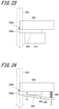
FIG. 23 or 24 in order to set the sample on the shielding member. - In
FIG. 23 , asample 200 is attached and fixed to asample placing stand 210. A plate-shaped shielding member 220 is arranged on the opposite side of thesample placing stand 210. Thesample 200 is sandwiched and fixed between thesample placing stand 210 and theshielding member 220. - Meanwhile, in
FIG. 24 , thesample 200 is fixed with aclip 240. Theclip 240 is supported so as to be swingable about afulcrum portion 250. Theclip 240 is biased in one direction by force F1 of aspring 260. The plate-shaped shielding member 220 is arranged on the opposite side of theclip 240. Thesample 200 is fixed to theshielding member 220 by pressing force F2 applied from theclip 240 to thesample 200. The pressing force F2 is force generated by biasing theclip 240 in one direction by the force F1 of thespring 260. - The
sample 200 fixed as described above is irradiated with anion beam 230 emitted from an ion source (not illustrated) via theshielding member 220. As a result, apart 200a of thesample 200 protruding from anedge portion 220a of theshielding member 220 is removed by etching. Therefore, a cross section of thesample 200 is formed immediately below theedge portion 220a of theshielding member 220. - However, the conventional ion milling apparatus has the following problems.
- In a case where the
sample 200 is irradiated with theion beam 230 via theshielding member 220 as described above, the current density of theion beam 230 that determines a processing rate decreases as theion beam 230 goes away from the ion source. That is, the longer a distance from the ion source is, the lower the processing rate is. The distance from the ion source increases as theion beam 230 goes away from theshielding member 220 in the thickness direction of thesample 200, that is, as theion beam 230 goes toward the lower parts ofFIGS. 23 and 24 . Therefore, when a processing rate on an upper surface side of thesample 200 close to theshielding member 220 is compared with a processing rate on a lower surface side of thesample 200 far from theshielding member 220, the processing rate is lower on the lower surface side of thesample 200 than on the upper surface side. As a result, as illustrated inFIG. 25 , across section 200b of thesample 200 has a shape gently inclined from the upper surface side of thesample 200 toward the lower surface side thereof. In addition, the inclination of thecross section 200b of thesample 200 appears more remarkably as the thickness dimension of thesample 200 increases. - Therefore, for example, as illustrated in
FIG. 26 , in a case where a processing target of thesample 200 is a through-hole 300, the following problems occur even if an ion beam is emitted with theedge portion 220a of theshielding member 220 accurately aligned with the center of the through-hole 300. When the cross section of thesample 200 processed by the irradiation of the ion beam is inclined as illustrated by a wavy line in the figure, apart 300a of the through-hole 300 remains without being subjected to cross-section processing on the lower surface side of thesample 200. As a result, as illustrated inFIG. 27 , thepart 300a of the through-hole 300 does not appear in thecross section 200b of thesample 200 and cannot be observed. In addition, in order to eliminate the inclination of thecross section 200b of thesample 200, it is necessary to continue to irradiate the lower surface side of thesample 200 with an ion beam having a low current density, which increases processing time. - An object of the present invention is to provide an ion milling apparatus and a method of manufacturing a sample that are capable of efficiently manufacturing a sample having a cross section whose inclination is reduced.
- An ion milling apparatus according to the present invention includes a pair of shielding members that sandwich a sample and an ion source that irradiates the sample with an ion beam. The ion milling apparatus is configured to be capable of irradiating the sample with the ion beam in a first mode and a second mode. The first mode is a mode of irradiating the sample with the ion beam via one shielding member of the pair of shielding members. The second mode is a mode of irradiating the sample with the ion beam via the other shielding member.
- A method of manufacturing a sample according to the present invention includes a first processing step of sandwiching a sample between a pair of shielding members and irradiating the sample with an ion beam via one of the shielding members and a second processing step of irradiating the sample with the ion beam via the other shielding member.
- According to the present invention, it is possible to efficiently manufacture a sample having a cross section whose inclination is reduced.
-
-
FIG. 1 is a schematic diagram illustrating a configuration example of an ion milling apparatus according to a first embodiment of the present invention; -
FIG. 2 is an enlarged diagram of a main part of the ion milling apparatus according to the first embodiment of the present invention; -
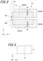
FIG. 3 is a diagram (part 1) for describing a procedure in the case of processing a sample using the ion milling apparatus according to the first embodiment of the present invention; -
FIG. 4 is a diagram (part 1) illustrating a state of the sample processed with the ion milling apparatus according to the first embodiment of the present invention; -
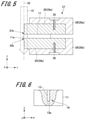
FIG. 5 is a diagram (part 2) for describing a procedure in the case of processing the sample using the ion milling apparatus according to the first embodiment of the present invention; -
FIG. 6 is a diagram (part 2) illustrating a state of the sample processed with the ion milling apparatus according to the first embodiment of the present invention; -
FIG. 7 is a diagram (part 3) for describing a procedure in the case of processing the sample using the ion milling apparatus according to the first embodiment of the present invention; -
FIG. 8 is a diagram (part 3) illustrating a state of the sample processed with the ion milling apparatus according to the first embodiment of the present invention; -
FIG. 9 is a diagram (part 4) for describing a procedure in the case of processing the sample using the ion milling apparatus according to the first embodiment of the present invention; -
FIG. 10 is a diagram (part 4) illustrating a state of the sample processed with the ion milling apparatus according to the first embodiment of the present invention; -
FIG. 11 is an enlarged diagram of a main part of an ion milling apparatus according to a second embodiment of the present invention; -
FIG. 12 is a diagram (part 1) for describing a procedure in the case of processing a sample using the ion milling apparatus according to the second embodiment of the present invention; -
FIG. 13 is a diagram (part 2) for describing a procedure in the case of processing the sample using the ion milling apparatus according to the second embodiment of the present invention; -
FIG. 14 is a diagram (part 3) for describing a procedure in the case of processing the sample using the ion milling apparatus according to the second embodiment of the present invention; -
FIG. 15 is a diagram (part 4) for describing a procedure in the case of processing the sample using the ion milling apparatus according to the second embodiment of the present invention; -
FIG. 16 is a diagram (part 5) for describing a procedure in the case of processing the sample using the ion milling apparatus according to the second embodiment of the present invention; -
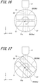
FIG. 17 is a diagram (part 6) for describing a procedure in the case of processing the sample using the ion milling apparatus according to the second embodiment of the present invention; -
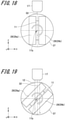
FIG. 18 is a diagram (part 7) for describing a procedure in the case of processing the sample using the ion milling apparatus according to the second embodiment of the present invention; -
FIG. 19 is a diagram (part 8) for describing a procedure in the case of processing the sample using the ion milling apparatus according to the second embodiment of the present invention; -
FIG. 20 is a diagram (part 1) for describing a configuration and an operation of an ion milling apparatus according to a third embodiment of the present invention; -
FIG. 21 is a diagram (part 2) for describing the configuration and an operation of the ion milling apparatus according to the third embodiment of the present invention; -
FIG. 22 illustrates a diagram for describing a modification of the ion milling apparatus according to the third embodiment of the present invention; -
FIG. 23 is a diagram illustrating a first example of a conventional ion milling apparatus; -
FIG. 24 is a diagram illustrating a second example of the conventional ion milling apparatus; -
FIG. 25 is a diagram for describing a cross-sectional shape of a sample formed by the conventional ion milling apparatus; -
FIG. 26 is a diagram (part 1) for describing problems caused by the conventional ion milling apparatus; and -
FIG. 27 is a diagram (part 2) for describing the problems caused by the conventional ion milling apparatus. - Hereinafter, embodiments of the present invention will be described in detail with reference to the drawings. In the present specification and the drawings, elements having substantially the same function or configuration will be denoted by the same reference numerals, and redundant description will be omitted.
-
FIG. 1 is a schematic diagram illustrating a configuration example of anion milling apparatus 10 according to a first embodiment of the present invention. - The
ion milling apparatus 10 illustrated inFIG. 1 is used, for example, for manufacturing a sample to be observed with a scanning electron microscope or a transmission electron microscope, or for manufacturing a sample to be analyzed with an electron probe microanalyzer, an auger microscope, or the like. Theion milling apparatus 10 is an apparatus that irradiates asample 11 that is an object to be processed with anion beam 12 to process thesample 11 into a shape suitable for observation with a scanning electron microscope or a transmission electron microscope. Thesample 11 is formed in a flat plate shape. - As illustrated in
FIG. 1 , theion milling apparatus 10 includes avacuum chamber 15, a sample stage pull-outmechanism 16, anion source 17, asample stage 18, arotation mechanism 19, anevacuation unit 20, anevacuation control unit 21, acamera 22, acontrol unit 23, avoltage power supply 24, arotation drive unit 25, and adisplay unit 26. Thecontrol unit 23 includes an ionsource control unit 23a and arotation control unit 23b. - The
vacuum chamber 15 is a hollow chamber. Theevacuation unit 20 is connected to thevacuum chamber 15. Driving of theevacuation unit 20 is controlled by theevacuation control unit 21. Theevacuation unit 20 is driven under the control of theevacuation control unit 21 to discharge air in thevacuum chamber 15. - The sample stage pull-out
mechanism 16 is a mechanism for pulling out thesample stage 18 from thevacuum chamber 15. The sample stage pull-outmechanism 16 is attached to thevacuum chamber 15 so that the sample stage pull-outmechanism 16 is openable and closable so as to close an opening of thevacuum chamber 15. Thesample stage 18 and therotation mechanism 19 are attached to the sample stage pull-outmechanism 16. - In a state in which the sample stage pull-out
mechanism 16 closed, thesample stage 18 is accommodated in thevacuum chamber 15. In addition, in a state in which the sample stage pull-outmechanism 16 is opened, therotation mechanism 19 is arranged while being pulled out to the outside of thevacuum chamber 15. The open and close states of the sample stage pull-outmechanism 16 are switchable by moving the sample stage pull-outmechanism 16 with respect to thevacuum chamber 15 in a left-right direction inFIG. 1 . Thesample stage 18 is a stage that supports thesample 11 via thesample holder 27. Thesample holder 27 is a holder that supports thesample 11. Thesample holder 27 includes aholder body 28 that serve as a base and a shieldingmember 29. Thesample holder 27 is attachable and detachable to and from thesample stage 18. The shieldingmember 29 is a member that shields thesample 11. The shieldingmember 29 is formed in a plate shape. - The
rotation mechanism 19 is a mechanism that rotates thesample holder 27 via thesample stage 18. Arotation axis 19a of therotation mechanism 19 is arranged in a direction orthogonal to acentral axis 32 of theion beam 12 and parallel to a direction (Y direction in the figures) in which thesample 11 protrudes from the shieldingmember 29. Therotation mechanism 19 rotates thesample holder 27 according to the driving of therotation drive unit 25. At this time, thesample holder 27 rotates about therotation axis 19a of therotation mechanism 19. Therotation control unit 23b controls the rotation of thesample holder 27 via therotation drive unit 25. Therotation mechanism 19 may be a mechanism that rotates thesample holder 27 integrally with thesample stage 18, or may be a mechanism that rotates thesample holder 27 separately from thesample stage 18. - The
ion source 17 is arranged in an upper portion of thevacuum chamber 15, that is, in a ceiling portion. Theion source 17 is a portion that emits theion beam 12. Theion source 17 includes, for example, a gas ion gun. The gas ion gun is an ion gun that emits an ion beam by ionizing argon gas by discharge. Theion source 17 emits theion beam 12 vertically downward toward the internal space of thevacuum chamber 15. - In the following description, one direction of biaxial directions orthogonal to the
central axis 32 of theion beam 12 is defined as an X direction and the other direction is defined as a Y direction. In addition, a direction parallel to thecentral axis 32 of theion beam 12 and orthogonal to the X direction and the Y direction is defined as a Z direction. In the first embodiment of the present invention, the X direction and the Y direction are horizontal biaxial directions, and the Z direction is a vertical direction (up-down direction). In addition, thecentral axis 32 of theion beam 12 is an axis parallel to the vertical direction. - The
voltage power supply 24 is electrically connected to theion source 17. Thevoltage power supply 24 is a power supply that applies a voltage to theion source 17. Thevoltage power supply 24 applies a voltage to theion source 17 under the control of the ionsource control unit 23a, whereby theion beam 12 is emitted from theion source 17. The ionsource control unit 23a controls theion source 17 via thevoltage power supply 24. - The
camera 22 is provided so as to be rotatable by acamera rotation mechanism 30. Thecamera rotation mechanism 30 is attached to an upper portion of the sample stage pull-outmechanism 16 and moves integrally with the sample stage pull-outmechanism 16. Thecamera 22 can be arranged at a first position and a second position by the rotation of thecamera rotation mechanism 30. The first position is a position where an optical axis of thecamera 22 is arranged parallel to the Z direction. When thecamera 22 is arranged at the first position, the optical axis of thecamera 22 is arranged so as to pass through a processing position of thesample 11. As illustrated inFIG. 1 , the second position is a position where thecamera 22 is arranged to be greatly inclined with respect to the Z direction. - The
camera 22 photographs thesample 11 supported by thesample holder 27 and the shieldingmember 29. For this photographing, an optical microscope may be used instead of thecamera 22. Thedisplay unit 26 displays an image captured by thecamera 22. Thedisplay unit 26 includes a monitor (display) or a touch panel. -
FIG. 2 is an enlarged diagram of a main part of theion milling apparatus 10 according to the first embodiment of the present invention. As illustrated inFIG. 2 , thesample holder 27 includes a pair of shielding members 29 (29a and 29b) sandwiching thesample 11. The reason why thesample holder 27 is provided with the pair of shieldingmembers 29 is to enable thesample 11 to be processed from either an upper side or a lower side. Theion milling apparatus 10 according to the first embodiment of the present invention has a configuration in which an orientation of thesample holder 27 supporting thesample 11 can be vertically inverted, or a configuration in which the attachment position of theion source 17 in thevacuum chamber 15 can be vertically inverted. In the following description, the shieldingmember 29 arranged on the upper side inFIG. 2 is referred to as afirst shielding member 29a, and the shieldingmember 29 arranged on the lower side is referred to as asecond shielding member 29b. - A
distal end surface 31a of thefirst shielding member 29a is slightly inclined with respect to thecentral axis 32 of theion beam 12, and thedistal end surface 32a of thesecond shielding member 29b is also slightly inclined with respect to thecentral axis 32 of theion beam 12. The inclination of thedistal end surface 31a is to enable anedge portion 31b of thefirst shielding member 29a and a protruding amount of thesample 11 from theedge portion 31b to be observed by thecamera 22. Similarly, the inclination of thedistal end surface 32a is to enable anedge portion 32b of thesecond shielding member 29b and a protruding amount of thesample 11 from theedge portion 32b to be observed by thecamera 22. - The
first shielding member 29a is fixed to afirst holder body 28a by ascrew 35. Thesecond shielding member 29b is fixed to thesecond holder body 28b by ascrew 36. Theholder body 28 includes thefirst holder body 28a and thesecond holder body 28b. The rear end portion of each of thefirst holder body 28a and thesecond holder body 28b can be mounted on thesample stage 18 from either an up or down direction by, for example, a dovetail groove type coupling structure. - Note that a means for fixing the
first shielding member 29a to thefirst holder body 28a is not limited to thescrew 35 described above. For example, a magnet may be used, or a plate spring, a pin, or the like may be used. - In a case where the
first shielding member 29a is fixed to thefirst holder body 28a with a magnet, one of thefirst holder body 28a and thefirst shielding member 29a includes a magnetic material, the magnet is embedded in the other, and thefirst shielding member 29a is fixed to thefirst holder body 28a by magnetic attraction force generated between the magnetic material and the magnet. In addition, in a case where a leaf spring, a pin, or the like is used, thefirst holder body 28a and thefirst shielding member 29a are sandwiched by the leaf spring, the pin, or the like, whereby thefirst shielding member 29a is fixed to thefirst holder body 28a. The points described above similarly apply to a means for fixing thesecond shielding member 29b to thesecond holder body 28b. - Subsequently, procedures in the case of processing the sample using the
ion milling apparatus 10 according to the first embodiment of the present invention will be described. The procedures to be described below include a method of manufacturing a sample. - First, as illustrated in
FIG. 3 , thesample 11 is set in thesample holder 27. In the first embodiment of the present invention, thesample 11 is sandwiched by the pair of shielding members 29 (29a and 29b) included in thesample holder 27, whereby thesample 11 is supported. At this time, thesample 11 is sandwiched by the pair of shieldingmembers 29 so that theedge portion 31b of thefirst shielding member 29a and theedge portion 32b of thesecond shielding member 29b are at the same position in the Y direction, that is, flush with each other. Thesample 11 is arranged to protrude from each of theedge portions 31b of thefirst shielding member 29a and theedge portion 32b of thesecond shielding member 29b by a predetermined amount. The protruding amount of thesample 11 is defined on the basis of each of theedge portions 31b of thefirst shielding member 29a and theedge portion 32b of thesecond shielding member 29b. Although the protruding amount of thesample 11 depends on the position of a processing target, the protruding amount of thesample 11 is often set within a range of 50 µm or more and 100 µm or less. - After the
sample 11 is set in thesample holder 27 as described above, thesample holder 27 is mounted on thesample stage 18. Thesample holder 27 is mounted with thesample stage 18 pulled out to the outside of thevacuum chamber 15 by the sample stage pull-outmechanism 16. At this time, thesample holder 27 is mounted on thesample stage 18 with thefirst shielding member 29a on the upper side and thesecond shielding member 29b on the lower side. In addition, the protruding amount of thesample 11 is confirmed using a photographed image of thecamera 22. In a case where the protruding amount of thesample 11 is confirmed, thecamera 22 is arranged at the first position by the rotation of thecamera rotation mechanism 30, and in this state, the photographed image of thecamera 22 is displayed on thedisplay unit 26. As a result, an operator of theion milling apparatus 10 can confirm the protruding amount of thesample 11 using the photographed image of thecamera 22 displayed on thedisplay unit 26. - Next, after the
camera 22 is arranged at the second position by the rotation of thecamera rotation mechanism 30, thesample stage 18 is pushed into thevacuum chamber 15 by the sample stage pull-outmechanism 16, whereby thesample stage 18 is accommodated in thevacuum chamber 15. At this time, thesample holder 27 and thesample 11 are accommodated in thevacuum chamber 15 together with thesample stage 18. At this stage, as illustrated inFIG. 4 , a through-hole 13 formed in thesample 11 is not exposed to the outside. The through-hole 13 serves as a target when thesample 11 after processing by theion milling apparatus 10 is observed with an electron microscope. Therefore, theion milling apparatus 10 needs to process thesample 11 so that the through-hole 13 of thesample 11 is set as the processing target and the entire through-hole 13 is exposed to the outside. - In the first embodiment of the present invention, the
sample 11 is processed by a first processing step and a second processing step. The first processing step is a step of processing thesample 11 in a first mode of irradiating thesample 11 with theion beam 12 via thefirst shielding member 29a. The second processing step is a step of processing thesample 11 in a second mode of irradiating thesample 11 with theion beam 12 via thesecond shielding member 29b. In both the first processing step and the second processing step, theevacuation unit 20 evacuates the air in thevacuum chamber 15 according to a control command from theevacuation control unit 21, whereby thesample 11 is processed in a state in which the inside of thevacuum chamber 15 is maintained at a predetermined degree of vacuum. - In the first processing step, the
sample 11 is irradiated with theion beam 12 via thefirst shielding member 29a by emitting theion beam 12 from theion source 17 in a state illustrated inFIG. 3 . At this time, theion source 17 emits theion beam 12 when thevoltage power supply 24 receives a control command from the ionsource control unit 23a and applies a voltage to theion source 17. As a result, thesample 11 is etched by irradiation with theion beam 12 as illustrated inFIG. 5 . At this time, thesample 11 is etched more (faster) on an upstream side where a current density is high in an irradiation direction of theion beam 12, that is, the upper side than the lower side. Therefore, in the first embodiment of the present invention, the first processing step ends in a stage in which across section 14 including the through-hole 13 appears in thesample 11 due to the irradiation of theion beam 12 described above, as illustrated inFIG. 6 and apart 13a of the through-hole 13 remains without being subjected to cross-section processing. At this stage, as illustrated inFIGS. 5 and 6 , part of thesample 11 protruding from theedge portion 31b of thefirst shielding member 29a remains as aprotrusion 11a, and the lower side of thecross section 14 of thesample 11 is inclined. - Next, the inside of the
vacuum chamber 15 is returned to a normal temperature and normal pressure state, and thesample stage 18 is pulled out to the outside of thevacuum chamber 15 by the sample stage pull-outmechanism 16. Next, after thesample holder 27 is removed from thesample stage 18, the orientation of thesample holder 27 is changed. Specifically, as illustrated inFIG. 7 , the orientation of thesample holder 27 is vertically inverted, and thesample holder 27 is mounted on thesample stage 18. Next, thesample stage 18 is pushed into thevacuum chamber 15 by the sample stage pull-outmechanism 16, whereby thesample stage 18 is accommodated in thevacuum chamber 15. As a result, thesample 11 and thesample holder 27 are accommodated in thevacuum chamber 15 together with thesample stage 18. In addition, as illustrated inFIG. 8 , thesample 11 is arranged in an orientation in which thepart 13a of the through-hole 13 is located on the upper side. In addition, as illustrated inFIG. 7 , theprotrusion 11a of thesample 11, which is a processing residue in the first processing step, is arranged on the upper side by vertically inverting thesample holder 27 described above. - In the second processing step, the
sample 11 is irradiated with theion beam 12 via thesecond shielding member 29b by emitting theion beam 12 from theion source 17 in a state illustrated inFIG. 7 . As a result, thesample 11 is etched by irradiation with theion beam 12 as illustrated inFIG. 9 . At this time, theprotrusion 11a (seeFIG. 7 ) of thesample 11 is arranged on the upstream side where the current density is high in the irradiation direction of theion beam 12, that is, on the upper side. Therefore, theprotrusion 11a of thesample 11 is efficiently etched by irradiation with theion beam 12. In the first embodiment of the present invention, the second processing step ends in a stage in which the entire through-hole 13 appears in thecross section 14 of thesample 11 due to the irradiation of theion beam 12 described above, as illustrated inFIG. 10 and the inclination of thecross section 14 is reduced to be sufficiently small. - As described above, the
ion milling apparatus 10 according to the first embodiment of the present invention includes the pair of shieldingmembers 29 sandwiching thesample 11. Then, in the first processing step, thesample 11 is irradiated with theion beam 12 via thefirst shielding member 29a, and in the second processing step, thesample 11 is irradiated with theion beam 12 via thesecond shielding member 29b. As a result, thesample 11 can be processed by irradiating thesample 11 with theion beam 12 from one side and the other side in the Z direction. That is, thesample 11 can be processed from both upper and lower surfaces. Therefore, it is possible to efficiently manufacture thesample 11 having thecross section 14 whose inclination is reduced. In addition, processing time until a desired processed cross section is obtained can be shortened. - The effect of shortening the processing time can be more remarkably obtained, for example, in a case where the through-
hole 13 of thesample 11 having a large thickness dimension is exposed to the outside by cross-section processing using theion beam 12. Specifically, when thesample 11 is irradiated with theion beam 12 from only the one side in the Z direction, the processing rate decreases due to a decrease in the current density of theion beam 12 on the downstream side of theion beam 12 where a distance from theion source 17 increases, and the processing time until a desired processed cross section is obtained increases. In contrast, when thesample 11 is irradiated with theion beam 12 from the one side and the other side in the Z direction, thesample 11 can be processed in a state in which the current density of theion beam 12 is high, that is, at a high processing rate. Therefore, the processing time until a desired processed cross section is obtained can be shortened as compared with a case where theion beam 12 is irradiated only from the one side in the Z direction. - Note that in the first embodiment, first, the
sample 11 is irradiated with theion beam 12 via thefirst shielding member 29a, and then thesample 11 is irradiated with theion beam 12 via thesecond shielding member 29b. However, the present invention is not limited thereto, and the processing order may be reversed. Specifically, first, thesample 11 may be irradiated with theion beam 12 via thesecond shielding member 29b, and then thesample 11 may be irradiated with theion beam 12 via thefirst shielding member 29a. - In addition, in the first embodiment, after the first processing step ends and before the second processing step starts, the orientation of the
sample holder 27 attached to thesample stage 18 is vertically inverted. However, the present invention is not limited thereto, and the position of theion source 17 may be vertically inverted instead of vertically inverting the orientation of thesample holder 27. - In addition, in the first embodiment, in a case where the
sample 11 is irradiated with theion beam 12 via thefirst shielding member 29a, thesample 11 may be inclined by therotation mechanism 19. This point similarly applies to a case where thesample 11 is irradiated with theion beam 12 via thesecond shielding member 29b. By performing such an inclination operation in the first processing step and the second processing step, it is possible to remove processing streaks generated in an ion beam irradiation direction and expand a range of theion beam 12 with which thesample 11 is irradiated, that is, a processing range. In addition, in the case of performing the inclination operation described above, it is preferable that thesample stage 18 has a eucentric function so that the upper surface of thesample 11 arranged vertically upward becomes the eucentric center. - Next, a second embodiment of the present invention will be described.
- An
ion milling apparatus 10 according to the second embodiment of the present invention is configured to be switchable between a first mode and a second mode described above by rotating asample holder 27 by arotation mechanism 19. -
FIG. 11 is an enlarged diagram of a main part of theion milling apparatus 10 according to the second embodiment of the present invention. - As illustrated in
FIG. 11 , thesample holder 27 includes a pair of shielding members 29 (29a and 29b) sandwiching asample 11, and a pair of holder bodies 28 (28a and 28b) supporting thesample 11 via the pair of shieldingmembers 29. The pair ofholder bodies 28 is attached to arotating body 37. Therefore, thesample 11, the pair of shieldingmembers 29, and the pair ofholder bodies 28 rotate integrally with the rotatingbody 37. The rotatingbody 37 is one of elements constituting therotation mechanism 19 described above. Therotation mechanism 19 is capable of rotating thesample holder 27 by 360°. However, in order to switch between the first mode and the second mode by the rotation of thesample holder 27, therotation mechanism 19 only needs to be capable of rotating thesample holder 27 by 180°. The technical significance of being capable of rotating thesample holder 27 by 360° will be described later. - Next, procedures in the case of processing the
sample 11 using theion milling apparatus 10 according to the second embodiment of the present invention will be described. The procedures to be described below include a method of manufacturing a sample. - First, as illustrated in
FIG. 12 , thesample 11 is sandwiched by the pair of shieldingmembers 29 with afirst shielding member 29a on an upper side and asecond shielding member 29b on a lower side, and in this state, thesample holder 27 is mounted on asample stage 18. Next, after a protruding amount of thesample 11 is confirmed using acamera 22 and adisplay unit 26, thesample stage 18 is accommodated in avacuum chamber 15. The procedures described so far are similar to the procedures in the first embodiment described above. The subsequent procedures are automatically performed under the control of anevacuation control unit 21 and a control unit 23 (ionsource control unit 23a androtation control unit 23b) . - Next, the
evacuation control unit 21 drives anevacuation unit 20 to evacuate air in thevacuum chamber 15. In addition, theevacuation control unit 21 maintains the inside of thevacuum chamber 15 at a predetermined degree of vacuum until the processing of thesample 11 ends. - Next, the
control unit 23 processes thesample 11 by irradiating thesample 11 with anion beam 12 while thesample holder 27 is rotated. The rotation of thesample holder 27 is performed by arotation drive unit 25 driving therotation mechanism 19 according to a control command from therotation control unit 23b. The irradiation of theion beam 12 is performed by avoltage power supply 24 applying a voltage to theion source 17 according to a control command from the ionsource control unit 23a. -
FIGS. 12 to 19 are time-series diagrams illustrating how thesample 11 is processed using theion milling apparatus 10 according to the second embodiment of the present invention.FIG. 12 illustrates a state in which a rotation angle of thesample 11 is 0°, andFIG. 13 illustrates a state in which the rotation angle of thesample 11 is 45°.FIG. 14 illustrates a state in which the rotation angle of thesample 11 is 90°, andFIG. 15 illustrates a state in which the rotation angle of thesample 11 is 135°.FIG. 16 illustrates a state in which the rotation angle of thesample 11 is 180°, andFIG. 17 illustrates a state in which the rotation angle of thesample 11 is 225°.FIG. 18 illustrates a state in which the rotation angle of thesample 11 is 270°, andFIG. 19 illustrates a state in which the rotation angle of thesample 11 is 315°. Note that a state in which the rotation angle of thesample 11 is 360° is the same as the state in which the rotation angle of thesample 11 is 0°. - First, as illustrated in
FIG. 12 , thecontrol unit 23 irradiates thesample 11 with theion beam 12 from theion source 17 in a state in which thefirst shielding member 29a is arranged on the upper side and thesecond shielding member 29b is arranged on the lower side. At this point, each of thefirst shielding member 29a and thesecond shielding member 29b is arranged parallel to a horizontal plane. In addition, thesample 11 is irradiated with theion beam 12 via thefirst shielding member 29a, and thesample 11 is arranged vertically without being inclined with respect to acentral axis 32 of theion beam 12. - Next, as illustrated in
FIG. 13 , thecontrol unit 23 rotates thesample 11 integrally with the pair of shielding members 29 (29a and 29b) while thesample 11 is irradiated with theion beam 12 from theion source 17. At this time, thesample 11 is irradiated with theion beam 12 via thefirst shielding member 29a. In addition, thesample 11 is arranged to be inclined downward to the right in the figure with respect to thecentral axis 32 of theion beam 12. Thesample 11 is rotated by therotation mechanism 19. At this time, therotation mechanism 19 rotates thesample 11 together with the rotatingbody 37. Aprocessing position 11b of thesample 11 is arranged on thecentral axis 32 of theion beam 12. Note that inFIG. 13 , thesample 11 is rotated in a clockwise direction in the figure, but the rotation direction of thesample 11 may be a counterclockwise direction. - Next, as illustrated in
FIG. 14 , thecontrol unit 23 stops the irradiation of thesample 11 with theion beam 12 from theion source 17. The irradiation of theion beam 12 is stopped when the voltage is not applied from thevoltage power supply 24 to theion source 17. A timing of stopping the irradiation of theion beam 12 is controlled by the ionsource control unit 23a. Specifically, the ionsource control unit 23a controls thevoltage power supply 24 to stop the irradiation of theion beam 12 at a timing at which theion beam 12 emitted from theion source 17 cannot be shielded by the shielding member 29 (29a) or a timing before the timing is reached (more preferably, immediately before the timing is reached). The timing at which theion beam 12 cannot be shielded by the shieldingmember 29 refers to a timing at which thesample 11 is irradiated directly with theion beam 12 emitted from theion source 17. - By stopping the irradiation of the
ion beam 12 as described above, the processing of aside surface 11c of thesample 11 can be reduced. - Next, as illustrated in
FIG. 15 , thecontrol unit 23 restarts the irradiation of thesample 11 with theion beam 12 from theion source 17. At this time, thesample 11 is irradiated with theion beam 12 via thesecond shielding member 29b. In addition, thesample 11 is arranged to be inclined upward in the figure with respect to thecentral axis 32 of theion beam 12. A timing of restarting the irradiation of theion beam 12 is controlled by the ionsource control unit 23a. Specifically, the ionsource control unit 23a controls thevoltage power supply 24 to restart the irradiation of theion beam 12 at a timing at which theion beam 12 emitted from theion source 17 can be shielded by the shielding member 29 (29b) or a timing after the timing is reached (more preferably, immediately after the timing is reached). The timing at which theion beam 12 can be shielded by the shieldingmember 29 refers to a timing at which thesample 11 is not irradiated directly with theion beam 12 emitted from theion source 17. - By restarting the irradiation of the
ion beam 12 as described above, thesample 11 can be processed while theside surface 11c of thesample 11 is avoided. - Next, as illustrated in
FIG. 16 , thecontrol unit 23 rotates thesample 11 integrally with the pair of shielding members 29 (29a and 29b) while thesample 11 is irradiated with theion beam 12 from theion source 17. At this point, each of thefirst shielding member 29a and thesecond shielding member 29b is arranged while being parallel to the horizontal plane, thesecond shielding member 29b is arranged on the upper side, and thefirst shielding member 29a is arranged on the lower side. That is, at a time point ofFIG. 16 and a time point ofFIG. 12 , a positional relationship between the pair of shielding members 29 (29a and 29b) is reversed upside down. In addition, at the time point ofFIG. 16 , thesample 11 is irradiated with theion beam 12 via thesecond shielding member 29b, and thesample 11 is arranged vertically without being inclined with respect to thecentral axis 32 of theion beam 12. - Next, as illustrated in
FIG. 17 , thecontrol unit 23 rotates thesample 11 integrally with the pair of shielding members 29 (29a and 29b) while thesample 11 is irradiated with theion beam 12 from theion source 17. At this time, thesample 11 is irradiated with theion beam 12 via thesecond shielding member 29b. In addition, thesample 11 is arranged to be inclined downward to the right in the figure with respect to thecentral axis 32 of theion beam 12. - Next, as illustrated in
FIG. 18 , thecontrol unit 23 stops the irradiation of thesample 11 with theion beam 12 from theion source 17. A timing of stopping the irradiation of theion beam 12 is as described above. - Next, as illustrated in
FIG. 19 , thecontrol unit 23 restarts the irradiation of thesample 11 with theion beam 12 from theion source 17. At this time, thesample 11 is irradiated with theion beam 12 via thefirst shielding member 29a. In addition, thesample 11 is arranged to be inclined upward in the figure with respect to thecentral axis 32 of theion beam 12. A timing of restarting the irradiation of theion beam 12 is as described above. - Thereafter, as illustrated in
FIG. 12 , thecontrol unit 23 rotates thesample 11 in a state in which thefirst shielding member 29a is arranged on the upper side and thesecond shielding member 29b is arranged on the lower side, that is, until the rotation angle of thesample 11 reaches 360°. In addition, thecontrol unit 23 continues a rotation operation of thesample 11 until a sample cross section is formed, and stops the rotation of thesample 11 and stops the irradiation of theion beam 12 when the sample cross section is created. - As described above, the
ion milling apparatus 10 according to the second embodiment of the present invention has a first processing mode and a second processing mode. The first processing mode is a mode of irradiating thesample 11 with theion beam 12 via thefirst shielding member 29a by rotating thesample 11 sandwiched by the pair of shieldingmembers 29 together with the rotatingbody 37. The second processing mode is a mode of irradiating thesample 11 with theion beam 12 via thesecond shielding member 29b by rotating thesample 11 sandwiched by the pair of shieldingmembers 29 together with the rotatingbody 37. As a result, thesample 11 can be processed from both upper and lower surfaces. Therefore, it is possible to efficiently manufacture thesample 11 having a cross section whose inclination is reduced, and it is possible to shorten processing time until a desired processed cross section is obtained. - In addition, in the second embodiment of the present invention, the
sample 11 is processed by irradiating thesample 11 with theion beam 12 while thesample 11 is rotated integrally with thesample holder 27 and therotating body 37. Thus, it is possible to cancel processing streaks generated by the irradiation of theion beam 12. Thus, thesample 11 having a cross section with few processing streaks can be manufactured. In addition, by rotating thesample holder 27 supporting thesample 11 by 360°, the processing streaks can be canceled without unevenness. - In addition, in the first embodiment described above, it is necessary to change an orientation when the
sample holder 27 is mounted on thesample stage 18 in order to vertically invert the positional relationship between the pair of shieldingmembers 29. Therefore, it is necessary to provide a processing interruption step between the first processing step and the second processing step. The processing interruption step is to return the inside of thevacuum chamber 15 to a normal temperature and normal pressure state or to change the orientation of thesample holder 27 by pulling out thesample stage 18 from thevacuum chamber 15. In contrast, in the second embodiment, therotation mechanism 19 rotates thesample holder 27, whereby the positional relationship between the pair of shieldingmembers 29 can be vertically inverted. Therefore, in the second embodiment, after thevacuum chamber 15 is set to a predetermined degree of vacuum, the processing of thesample 11 can be continued without providing the processing interruption step described above. Therefore, according to the second embodiment, the processing of thesample 11 can end in a shorter time than in the first embodiment. - Note that in the second embodiment, the application of the voltage from the
voltage power supply 24 to theion source 17 is stopped, whereby the irradiation of thesample 11 with theion beam 12 is stopped, but the present invention is not limited thereto. For example, the irradiation of thesample 11 with theion beam 12 may be stopped by blocking theion beam 12 emitted from theion beam 12 with a shutter (not illustrated) arranged on an upstream side of thesample holder 27 while the application of the voltage from thevoltage power supply 24 to theion source 17 is continued. - In addition, in the second embodiment, the
rotation control unit 23b may rotate thesample 11 integrally with thesample holder 27 by 360° at a constant speed by controlling the rotation of thesample holder 27 via therotation drive unit 25, or may change the rotation speed of thesample holder 27 in the middle. For example, in a period in which thesample 11 is rotated by 360°, therotation control unit 23b may variably control the rotation speed of thesample holder 27 so that thesample 11 is rotated at a first speed during a period in which thesample 11 is irradiated with theion beam 12 and thesample 11 is rotated at a second speed higher than the first speed during a period in which thesample 11 is not irradiated with theion beam 12. By variably controlling the rotation speed of thesample holder 27 in this manner, it is possible to shorten time that does not contribute to processing of thesample 11 as compared with a case where the rotation speed of thesample holder 27 is controlled at a constant speed. Therefore, thesample 11 can be efficiently processed. - In addition, the
rotation control unit 23b may control the rotation of thesample holder 27 so that a first inclination operation and a second inclination operation are repeated at least once, preferably a plurality of times. The first inclination operation is an operation in which a state changes from a state illustrated inFIG. 15 , through a state illustrated inFIG. 16 , and to a state illustrated inFIG. 17 . The second inclination operation is an operation that is opposite to the first inclination operation and in which a state changes from the state illustrated inFIG. 17 , through the state illustrated inFIG. 16 , and to the state illustrated inFIG. 15 . Similarly, therotation control unit 23b may control the rotation of thesample holder 27 so that a first tilting operation and a second inclination operation are repeated at least once, preferably a plurality of times. The first inclination operation is an operation in which a state changes from a state illustrated inFIG. 19 , through a state illustrated inFIG. 12 , and to a state illustrated inFIG. 13 . The second inclination operation is an operation that is opposite to the first inclination operation and in which a state changes from the state illustrated inFIG. 13 , through the state illustrated inFIG. 12 , and to the state illustrated inFIG. 19 . By controlling the rotation of thesample holder 27 in this manner, it is possible to expand a range of theion beam 12 with which thesample 11 is irradiated, that is, a processing range can be expanded. In addition, in a case where the first inclination operation and the second inclination operation described above are performed, it is preferable that thesample stage 18 has a eucentric function so that the upper surface of thesample 11 arranged vertically upward becomes the eucentric center. - Next, a third embodiment of the present invention will be described.
- A configuration of an
ion milling apparatus 10 according to the third embodiment of the present invention is in common with the configuration of theion milling apparatus 10 in the first embodiment described above in that asample 11 is sandwiched and supported by a pair of shieldingmembers 29. However, the configuration of the ion milling apparatus according to the third embodiment is different from the configuration of the first embodiment in the number of ion sources 17. Specifically, as illustrated inFIGS. 20 and 21 , theion milling apparatus 10 according to the third embodiment includes afirst ion source 17a and asecond ion source 17b. - The
first ion source 17a and thesecond ion source 17b are arranged to face each other on the same axis passing through aprocessing position 11b of thesample 11. Thefirst ion source 17a emits anion beam 12 vertically downward, and thesecond ion source 17b emits anion beam 12 vertically upward. That is, thefirst ion source 17a and thesecond ion source 17b emit the ion beams 12 in directions opposite to each other in a vertical direction. In addition, thefirst ion source 17a irradiates thesample 11 with theion beam 12 via afirst shielding member 29a, and thesecond ion source 17b irradiates thesample 11 with theion beam 12 via asecond shielding member 29b. - In addition, the
ion milling apparatus 10 according to the third embodiment includes afirst shutter 38a and asecond shutter 38b. Thefirst shutter 38a is arranged in the vicinity of thefirst ion source 17a. In addition, thefirst shutter 38a is arranged between thefirst ion source 17a and thefirst shielding member 29a in a Z direction. Thesecond shutter 38b is arranged in the vicinity of thesecond ion source 17b. In addition, thesecond shutter 38b is arranged between thesecond ion source 17b and thesecond shielding member 29b in the Z direction. - The
first shutter 38a is a shutter that blocks anion beam 12b emitted from thesecond ion source 17b before thefirst ion source 17a. Thesecond shutter 38b is a shutter that blocks anion beam 12a emitted from thefirst ion source 17a before thesecond ion source 17b. Thefirst shutter 38a and thesecond shutter 38b each includes a material that is difficult to be etched even when the material is irradiated with theion beam 12, for example, titanium. - The
first shutter 38a is provided so as to be arrangeable at an opened position illustrated inFIG. 20 and a closed position illustrated inFIG. 21 . Thesecond shutter 38b is provided so as to be arrangeable at an opened position illustrated inFIG. 21 and a closed position illustrated inFIG. 20 . The arrangements of each of thefirst shutter 38a and thesecond shutter 38b are switched by a switching mechanism (not illustrated). The switching mechanism switches the arrangements of each of thefirst shutter 38a and thesecond shutter 38b using, for example, a solenoid or a motor as a drive source. In addition, the operation of the switching mechanism is controlled by acontrol unit 23. - In a case where the
first shutter 38a is arranged at the opened position, the passage of theion beam 12a emitted from thefirst ion source 17a is allowed by thefirst shutter 38a. In a case where thefirst shutter 38a is arranged at the closed position, the passage of theion beam 12b emitted from thesecond ion source 17b is blocked by thefirst shutter 38a. - In a case where the
second shutter 38b is arranged at the opened position, the passage of theion beam 12b emitted from thesecond ion source 17b is allowed by thesecond shutter 38b. In a case where thesecond shutter 38b is arranged at the closed position, the passage of theion beam 12a emitted from thefirst ion source 17a is blocked by thesecond shutter 38b. - Therefore, as illustrated in
FIG. 20 , when thefirst shutter 38a is arranged at the opened position, thesecond shutter 38b is arranged at the closed position, and theion beam 12a is emitted from thefirst ion source 17a, thesample 11 is irradiated with theion beam 12a via thefirst shielding member 29a. Therefore, thesample 11 is processed from an upper surface side toward a lower surface side. In addition, theion beam 12a is blocked by thesecond shutter 38b before thesecond ion source 17b. Therefore, damage to thesecond ion source 17b due to the irradiation with theion beam 12a is reduced. Consequently, thesecond ion source 17b can be protected from theion beam 12a. - Meanwhile, as illustrated in
FIG. 21 , when thefirst shutter 38a is arranged at the closed position, thesecond shutter 38b is arranged at the opened position, and theion beam 12b is emitted from thesecond ion source 17b, thesample 11 is irradiated with theion beam 12b via thesecond shielding member 29b. Therefore, thesample 11 is processed from the lower surface side toward the upper surface side. In addition, theion beam 12b is blocked by thefirst shutter 38a before thefirst ion source 17a. Therefore, damage to thefirst ion source 17a due to the irradiation with theion beam 12b is reduced. Consequently, thefirst ion source 17a can be protected from theion beam 12b. - Next, procedures in the case of processing the
sample 11 using theion milling apparatus 10 according to the third embodiment of the present invention will be described. The procedures to be described below include a method of manufacturing a sample. - First, as illustrated in
FIG. 20 , thesample 11 is sandwiched by the pair of shieldingmembers 29 with thefirst shielding member 29a on an upper side and thesecond shielding member 29b on a lower side, and in this state, thesample holder 27 is mounted on asample stage 18. Next, after a protruding amount of thesample 11 is confirmed using acamera 22 and adisplay unit 26, thesample stage 18 is accommodated in avacuum chamber 15. The procedures described so far are similar to the procedures in the first embodiment described above. - Next, by driving the switching mechanism described above, the
control unit 23 arranges thefirst shutter 38a at the opened position and arranges thesecond shutter 38b at the closed position as illustrated inFIG. 20 . Next, avoltage power supply 24 receives a control command from an ionsource control unit 23a and applies a voltage to thefirst ion source 17a. As a result, thefirst ion source 17a emits theion beam 12a. Thesample 11 is irradiated with theion beam 12a via thefirst shielding member 29a. Thereafter, when the time of irradiation with theion beam 12a by thefirst ion source 17a reaches predetermined time, thevoltage power supply 24 receives a control command from the ionsource control unit 23a and stops applying a voltage to thefirst ion source 17a. As a result, thefirst ion source 17a stops emitting theion beam 12a. - Next, by driving the switching mechanism described above, the
control unit 23 arranges thefirst shutter 38a at the closed position and arranges thesecond shutter 38b at the opened position as illustrated inFIG. 21 . Next, thevoltage power supply 24 receives a control command from the ionsource control unit 23a and applies a voltage to thesecond ion source 17b. As a result, thesecond ion source 17b emits theion beam 12b. Thesample 11 is irradiated with theion beam 12b via thesecond shielding member 29b. Thereafter, when the time of irradiation with theion beam 12b by thesecond ion source 17b reaches predetermined time, thevoltage power supply 24 receives a control command from the ionsource control unit 23a and stops applying the voltage to thesecond ion source 17b. As a result, thesecond ion source 17b stops emitting theion beam 12b. - As described above, in the
ion milling apparatus 10 according to the third embodiment of the present invention, thefirst ion source 17a irradiates thesample 11 sandwiched by the pair of shieldingmembers 29 with theion beam 12a via thefirst shielding member 29a, and thesecond ion source 17b irradiates the sample with theion beam 12b via thesecond shielding member 29b. As a result, thesample 11 can be processed from both upper and lower surfaces. Therefore, it is possible to efficiently manufacture thesample 11 having a cross section whose inclination is reduced, and it is possible to shorten processing time until a desired processed cross section is obtained. - In addition, in the
ion milling apparatus 10 according to the third embodiment, optical axes of thefirst ion source 17a and thesecond ion source 17b are adjustable, and thefirst ion source 17a and thesecond ion source 17b are arranged to face each other on the same axis passing through theprocessing position 11b of thesample 11. As a result, an irradiation position of theion beam 12a with which thesample 11 is irradiated from thefirst ion source 17a and an irradiation position of theion beam 12b with which thesample 11 is irradiated from thesecond ion source 17b can be easily and accurately aligned with each other. - In addition, the
ion milling apparatus 10 according to the third embodiment includes thefirst shutter 38a that blocks theion beam 12b emitted from thesecond ion source 17b before thefirst ion source 17a, and thesecond shutter 38b that blocks theion beam 12a emitted from thefirst ion source 17a before thesecond ion source 17b. Therefore, thesample 11 can be processed while each of thefirst ion source 17a and thesecond ion source 17b is protected from theion beam 12. - Note that in the third embodiment, first, the
sample 11 is irradiated with theion beam 12a via thefirst shielding member 29a by emitting theion beam 12a from thefirst ion source 17a, and then thesample 11 is irradiated with theion beam 12b via thesecond shielding member 29b by emitting theion beam 12b from thesecond ion source 17b. However, the present invention is not limited thereto, and the processing order may be reversed. Specifically, first, thesample 11 may be irradiated with theion beam 12b via thesecond shielding member 29b by emitting theion beam 12b from thesecond ion source 17b, and then thesample 11 may be irradiated with theion beam 12a via thefirst shielding member 29a by emitting theion beam 12a from thefirst ion source 17a. - In addition, in the third embodiment, an example in which the
first ion source 17a and thesecond ion source 17b are arranged on the same axis has been illustrated, but the present invention is not limited thereto, and thefirst ion source 17a and thesecond ion source 17b may be arranged on different axes as illustrated inFIG. 22 . Thefirst ion source 17a is arranged at a position shifted from a central axis of theion beam 12b so that thefirst ion source 17a is not irradiated with theion beam 12b emitted from thesecond ion source 17b. Thesecond ion source 17b is arranged at a position shifted from a central axis of theion beam 12a so that thesecond ion source 17b is not irradiated with theion beam 12a emitted from thefirst ion source 17a. - In addition, the
first ion source 17a emits theion beam 12a in an obliquely downward direction having an inclination with respect to a vertical axis (Z direction), and thesecond ion source 17b emits theion beam 12b in an obliquely upward direction having an inclination with respect to the vertical axis. Thesample 11 is irradiated with theion beam 12a emitted from thefirst ion source 17a via thefirst shielding member 29a, and thesample 11 is irradiated with theion beam 12b emitted from thesecond ion source 17b via thesecond shielding member 29b. In addition, the central axis of theion beam 12a emitted from thefirst ion source 17a and the central axis of theion beam 12b emitted from thesecond ion source 17b intersect with each other at theprocessing position 11b of thesample 11. - Even in a case where the
first ion source 17a and thesecond ion source 17b are arranged as described above, thesample 11 can be processed from both the upper and lower surfaces. Therefore, it is possible to efficiently manufacture thesample 11 having a cross section whose inclination is reduced, and it is possible to shorten processing time until a desired processed cross section is obtained. In addition, each of thefirst ion source 17a and thesecond ion source 17b can be protected from theion beam 12 without providing thefirst shutter 38a and thesecond shutter 38b. In addition, by simultaneously emitting theion beam 12a from thefirst ion source 17a and theion beam 12b from thesecond ion source 17b, processing can be simultaneously performed from the upper surface side and the lower surface side of thesample 11. As a result, it is possible to further shorten the processing time. - Note that in
FIG. 22 , thesample 11 is obliquely irradiated with each of theion beam 12a emitted from thefirst ion source 17a and theion beam 12b emitted from thesecond ion source 17b, but it is also possible to vertically irradiate thesample 11 with the each of theion beam 12a and theion beam 12b. Specifically, in a case where theion beam 12a is emitted from thefirst ion source 17a, it is possible to vertically irradiate thesample 11 with theion beam 12a by rotating thesample 11 by a predetermined angle in a counterclockwise direction ofFIG. 22 by arotation mechanism 19 described above. In addition, in a case where theion beam 12b is emitted from thesecond ion source 17b, it is possible to vertically irradiate thesample 11 with theion beam 12b by rotating thesample 11 by a predetermined angle in a clockwise direction ofFIG. 22 by therotation mechanism 19 described above. Furthermore, in order to expand a processing range by the irradiation of theion beam 12, the inclination operations described in the first embodiment and the second embodiment described above can be performed. -
- 10
- Ion milling apparatus
- 11
- Sample
- 11b
- Processing position
- 12, 12a, 12b
- Ion beam
- 17, 17a, 17b
- Ion source
- 18
- Sample stage
- 19
- Rotation mechanism
- 27
- Sample holder
- 29, 29a, 29b
- Shielding member
- 38a
- First shutter
- 38b
- Second shutter
Claims (10)
- An ion milling apparatus (10) comprising:a pair of shielding members (29a and 29b) sandwiching a sample (11); andan ion source (17) configured to irradiate the sample (11) with an ion beam (12), whereinthe ion milling apparatus (10) is configured to be capable of irradiating the sample (11) with the ion beam (12) in a first mode of irradiating the sample (11) with the ion beam (12) via one shielding member (29a) of the pair of shielding members (29a and 29b) and in a second mode of irradiating the sample (11) with the ion beam (12) via the other shielding member (29b).
- The ion milling apparatus (10) according to claim 1, further comprising:a sample holder (27) having the pair of shielding members (29a and 29b); anda sample stage (18) to and from which the sample holder (27) is attachable and detachable, whereinthe ion milling apparatus (10) is configured to be switchable between the first mode and the second mode by changing an orientation in which the sample holder (27) is mounted on the sample stage (18).
- The ion milling apparatus (10) according to claim 1, further comprising:a sample holder (27) having the pair of shielding members (29a and 29b);a sample stage (18) to and from which the sample holder (27) is attachable and detachable; anda rotation mechanism (19) configured to rotate the sample holder (27), whereinthe ion milling apparatus (10) is configured to be switchable between the first mode and the second mode by rotating the sample holder (27) by the rotation mechanism (19) .
- The ion milling apparatus (10) according to claim 3, wherein
the rotation mechanism (19) is capable of rotating the sample holder (27) by 360°. - The ion milling apparatus (10) according to claim 3 or 4, wherein
the rotation mechanism (19) is configured to rotate the sample holder (27) about a processing position (11b) of the sample (11). - The ion milling apparatus (10) according to claim 1, wherein
the ion source (17) includes a first ion source (17a) and a second ion source (17b),
the first ion source (17a) is configured to irradiate the sample (11) with an ion beam (12a) via the one shielding member (29a), and
the second ion source (17b) is configured to irradiate the sample (11) with an ion beam (12b) via the other shielding member (29b). - The ion milling apparatus (10) according to claim 6, wherein
the first ion source (17a) and the second ion source (17b) are arranged to face each other on the same axis passing through a processing position (11b) of the sample (11) . - The ion milling apparatus (10) according to claim 6 or 7, further comprising:a first shutter (38a) configured to block the ion beam (12b) emitted from the second ion source (17b) before the first ion source (17a); anda second shutter (38b) configured to block the ion beam (12a) emitted from the first ion source (17a) before the second ion source (17b).
- The ion milling apparatus (10) according to claim 6, wherein
the first ion source (17a) and the second ion source (17b) are arranged on different axes so that the ion beam emitted from one ion source (17a or 17b) of the first ion source (17a) and the second ion source (17b) is not emitted to the other ion source (17a or 17b). - A method of manufacturing a sample comprising:a first processing step of sandwiching a sample (11) by a pair of shielding members (29a and 29b) and irradiating the sample (11) with an ion beam (12) via one shielding member (29a); anda second processing step of irradiating the sample (11) with the ion beam (12) via the other shielding member (29b) .
Applications Claiming Priority (1)
| Application Number | Priority Date | Filing Date | Title |
|---|---|---|---|
| JP2020123495A JP7160868B2 (en) | 2020-07-20 | 2020-07-20 | Ion milling device and sample preparation method |
Publications (2)
| Publication Number | Publication Date |
|---|---|
| EP3944285A1 true EP3944285A1 (en) | 2022-01-26 |
| EP3944285B1 EP3944285B1 (en) | 2024-09-18 |
Family
ID=76890856
Family Applications (1)
| Application Number | Title | Priority Date | Filing Date |
|---|---|---|---|
| EP21185017.7A Active EP3944285B1 (en) | 2020-07-20 | 2021-07-12 | Ion milling apparatus and method of manufacturing sample |
Country Status (4)
| Country | Link |
|---|---|
| US (1) | US11621143B2 (en) |
| EP (1) | EP3944285B1 (en) |
| JP (1) | JP7160868B2 (en) |
| KR (1) | KR102901442B1 (en) |
Families Citing this family (4)
| Publication number | Priority date | Publication date | Assignee | Title |
|---|---|---|---|---|
| JP7218459B1 (en) | 2022-02-14 | 2023-02-06 | Dmg森精機株式会社 | Information processing equipment, machine tools and information processing programs |
| US12228484B2 (en) * | 2022-05-19 | 2025-02-18 | Fei Company | Broad ion beam (BIB) systems for more efficient processing of multiple samples |
| EP4283277A1 (en) | 2022-05-24 | 2023-11-29 | Leica Mikrosysteme GmbH | Sample holder, loading device, and method for inserting a sample into a sample holder |
| WO2024168045A1 (en) * | 2023-02-09 | 2024-08-15 | Gatan, Inc. | Apparatus and method for ion beam cross section polishing of extended sample regions |
Citations (3)
| Publication number | Priority date | Publication date | Assignee | Title |
|---|---|---|---|---|
| JP2005091094A (en) | 2003-09-16 | 2005-04-07 | Jeol Ltd | Sample preparation apparatus and sample preparation method |
| WO2015122713A1 (en) * | 2014-02-14 | 2015-08-20 | 한국과학기술원 | Cross section sample preparation apparatus and rotational cross section sample preparation apparatus |
| DE112016007058T5 (en) * | 2016-07-14 | 2019-03-28 | Hitachi High-Technologies Corporation | ion etching |
Family Cites Families (3)
| Publication number | Priority date | Publication date | Assignee | Title |
|---|---|---|---|---|
| KR101522875B1 (en) | 2014-02-14 | 2015-05-26 | 한국과학기술원 | Specimen preparation apparatus |
| EP3038131A1 (en) * | 2014-12-22 | 2016-06-29 | FEI Company | Improved specimen holder for a charged particle microscope |
| JP6796552B2 (en) | 2017-05-26 | 2020-12-09 | 日本電子株式会社 | Ion milling device and sample holder |
-
2020
- 2020-07-20 JP JP2020123495A patent/JP7160868B2/en active Active
-
2021
- 2021-07-06 KR KR1020210088432A patent/KR102901442B1/en active Active
- 2021-07-12 EP EP21185017.7A patent/EP3944285B1/en active Active
- 2021-07-19 US US17/378,864 patent/US11621143B2/en active Active
Patent Citations (3)
| Publication number | Priority date | Publication date | Assignee | Title |
|---|---|---|---|---|
| JP2005091094A (en) | 2003-09-16 | 2005-04-07 | Jeol Ltd | Sample preparation apparatus and sample preparation method |
| WO2015122713A1 (en) * | 2014-02-14 | 2015-08-20 | 한국과학기술원 | Cross section sample preparation apparatus and rotational cross section sample preparation apparatus |
| DE112016007058T5 (en) * | 2016-07-14 | 2019-03-28 | Hitachi High-Technologies Corporation | ion etching |
Also Published As
| Publication number | Publication date |
|---|---|
| EP3944285B1 (en) | 2024-09-18 |
| US20220020558A1 (en) | 2022-01-20 |
| US11621143B2 (en) | 2023-04-04 |
| KR20220011079A (en) | 2022-01-27 |
| JP2022020153A (en) | 2022-02-01 |
| KR102901442B1 (en) | 2025-12-16 |
| JP7160868B2 (en) | 2022-10-25 |
Similar Documents
| Publication | Publication Date | Title |
|---|---|---|
| EP3944285B1 (en) | Ion milling apparatus and method of manufacturing sample | |
| US10283317B2 (en) | High throughput TEM preparation processes and hardware for backside thinning of cross-sectional view lamella | |
| US20230369010A1 (en) | Ion Milling Device and Ion Milling Method | |
| US8642958B2 (en) | Composite charged particle beam apparatus and sample processing and observing method | |
| KR101249134B1 (en) | Charged particle beam apparatus | |
| US7297944B2 (en) | Ion beam device and ion beam processing method, and holder member | |
| US5907157A (en) | Method and apparatus for preparing specimen | |
| US20140061159A1 (en) | Composite charged particle beam apparatus and thin sample processing method | |
| US20100213386A1 (en) | Focused ion beam system and sample processing method using the same | |
| JP2000035390A (en) | Sectioning method | |
| CN114975047A (en) | Sample processing device and sample processing method | |
| KR20150134080A (en) | Fouced Ion Beam Apparatus | |
| JP4170048B2 (en) | Ion beam apparatus and ion beam processing method | |
| KR20200139732A (en) | Device for extracting and placing lamella | |
| US20230197401A1 (en) | Apparatus and Method for Milling Sample | |
| JP2002150984A (en) | Sample holder | |
| JP7757540B2 (en) | Ion milling device and processing method using the same | |
| KR102820384B1 (en) | Ion milling device | |
| WO2026047885A1 (en) | Charged particle beam device and sample piece transfer method | |
| WO2013121938A1 (en) | Charged particle beam device, sample mask unit, and conversion member | |
| JP2008224576A (en) | Sample processing equipment |
Legal Events
| Date | Code | Title | Description |
|---|---|---|---|
| PUAI | Public reference made under article 153(3) epc to a published international application that has entered the european phase |
Free format text: ORIGINAL CODE: 0009012 |
|
| STAA | Information on the status of an ep patent application or granted ep patent |
Free format text: STATUS: THE APPLICATION HAS BEEN PUBLISHED |
|
| AK | Designated contracting states |
Kind code of ref document: A1 Designated state(s): AL AT BE BG CH CY CZ DE DK EE ES FI FR GB GR HR HU IE IS IT LI LT LU LV MC MK MT NL NO PL PT RO RS SE SI SK SM TR |
|
| STAA | Information on the status of an ep patent application or granted ep patent |
Free format text: STATUS: REQUEST FOR EXAMINATION WAS MADE |
|
| 17P | Request for examination filed |
Effective date: 20220407 |
|
| RBV | Designated contracting states (corrected) |
Designated state(s): AL AT BE BG CH CY CZ DE DK EE ES FI FR GB GR HR HU IE IS IT LI LT LU LV MC MK MT NL NO PL PT RO RS SE SI SK SM TR |
|
| GRAP | Despatch of communication of intention to grant a patent |
Free format text: ORIGINAL CODE: EPIDOSNIGR1 |
|
| STAA | Information on the status of an ep patent application or granted ep patent |
Free format text: STATUS: GRANT OF PATENT IS INTENDED |
|
| INTG | Intention to grant announced |
Effective date: 20240430 |
|
| RAP3 | Party data changed (applicant data changed or rights of an application transferred) |
Owner name: JEOL LTD. |
|
| GRAS | Grant fee paid |
Free format text: ORIGINAL CODE: EPIDOSNIGR3 |
|
| GRAA | (expected) grant |
Free format text: ORIGINAL CODE: 0009210 |
|
| STAA | Information on the status of an ep patent application or granted ep patent |
Free format text: STATUS: THE PATENT HAS BEEN GRANTED |
|
| AK | Designated contracting states |
Kind code of ref document: B1 Designated state(s): AL AT BE BG CH CY CZ DE DK EE ES FI FR GB GR HR HU IE IS IT LI LT LU LV MC MK MT NL NO PL PT RO RS SE SI SK SM TR |
|
| REG | Reference to a national code |
Ref country code: GB Ref legal event code: FG4D |
|
| REG | Reference to a national code |
Ref country code: CH Ref legal event code: EP |
|
| REG | Reference to a national code |
Ref country code: IE Ref legal event code: FG4D |
|
| REG | Reference to a national code |
Ref country code: DE Ref legal event code: R096 Ref document number: 602021018872 Country of ref document: DE |
|
| REG | Reference to a national code |
Ref country code: LT Ref legal event code: MG9D |
|
| PG25 | Lapsed in a contracting state [announced via postgrant information from national office to epo] |
Ref country code: NO Free format text: LAPSE BECAUSE OF FAILURE TO SUBMIT A TRANSLATION OF THE DESCRIPTION OR TO PAY THE FEE WITHIN THE PRESCRIBED TIME-LIMIT Effective date: 20241218 |
|
| PG25 | Lapsed in a contracting state [announced via postgrant information from national office to epo] |
Ref country code: GR Free format text: LAPSE BECAUSE OF FAILURE TO SUBMIT A TRANSLATION OF THE DESCRIPTION OR TO PAY THE FEE WITHIN THE PRESCRIBED TIME-LIMIT Effective date: 20241219 Ref country code: FI Free format text: LAPSE BECAUSE OF FAILURE TO SUBMIT A TRANSLATION OF THE DESCRIPTION OR TO PAY THE FEE WITHIN THE PRESCRIBED TIME-LIMIT Effective date: 20240918 |
|
| PG25 | Lapsed in a contracting state [announced via postgrant information from national office to epo] |
Ref country code: BG Free format text: LAPSE BECAUSE OF FAILURE TO SUBMIT A TRANSLATION OF THE DESCRIPTION OR TO PAY THE FEE WITHIN THE PRESCRIBED TIME-LIMIT Effective date: 20240918 |
|
| PG25 | Lapsed in a contracting state [announced via postgrant information from national office to epo] |
Ref country code: LV Free format text: LAPSE BECAUSE OF FAILURE TO SUBMIT A TRANSLATION OF THE DESCRIPTION OR TO PAY THE FEE WITHIN THE PRESCRIBED TIME-LIMIT Effective date: 20240918 |
|
| PG25 | Lapsed in a contracting state [announced via postgrant information from national office to epo] |
Ref country code: HR Free format text: LAPSE BECAUSE OF FAILURE TO SUBMIT A TRANSLATION OF THE DESCRIPTION OR TO PAY THE FEE WITHIN THE PRESCRIBED TIME-LIMIT Effective date: 20240918 |
|
| REG | Reference to a national code |
Ref country code: NL Ref legal event code: MP Effective date: 20240918 |
|
| PG25 | Lapsed in a contracting state [announced via postgrant information from national office to epo] |
Ref country code: RS Free format text: LAPSE BECAUSE OF FAILURE TO SUBMIT A TRANSLATION OF THE DESCRIPTION OR TO PAY THE FEE WITHIN THE PRESCRIBED TIME-LIMIT Effective date: 20241218 |
|
| PG25 | Lapsed in a contracting state [announced via postgrant information from national office to epo] |
Ref country code: RS Free format text: LAPSE BECAUSE OF FAILURE TO SUBMIT A TRANSLATION OF THE DESCRIPTION OR TO PAY THE FEE WITHIN THE PRESCRIBED TIME-LIMIT Effective date: 20241218 Ref country code: NO Free format text: LAPSE BECAUSE OF FAILURE TO SUBMIT A TRANSLATION OF THE DESCRIPTION OR TO PAY THE FEE WITHIN THE PRESCRIBED TIME-LIMIT Effective date: 20241218 Ref country code: LV Free format text: LAPSE BECAUSE OF FAILURE TO SUBMIT A TRANSLATION OF THE DESCRIPTION OR TO PAY THE FEE WITHIN THE PRESCRIBED TIME-LIMIT Effective date: 20240918 Ref country code: HR Free format text: LAPSE BECAUSE OF FAILURE TO SUBMIT A TRANSLATION OF THE DESCRIPTION OR TO PAY THE FEE WITHIN THE PRESCRIBED TIME-LIMIT Effective date: 20240918 Ref country code: GR Free format text: LAPSE BECAUSE OF FAILURE TO SUBMIT A TRANSLATION OF THE DESCRIPTION OR TO PAY THE FEE WITHIN THE PRESCRIBED TIME-LIMIT Effective date: 20241219 Ref country code: FI Free format text: LAPSE BECAUSE OF FAILURE TO SUBMIT A TRANSLATION OF THE DESCRIPTION OR TO PAY THE FEE WITHIN THE PRESCRIBED TIME-LIMIT Effective date: 20240918 Ref country code: BG Free format text: LAPSE BECAUSE OF FAILURE TO SUBMIT A TRANSLATION OF THE DESCRIPTION OR TO PAY THE FEE WITHIN THE PRESCRIBED TIME-LIMIT Effective date: 20240918 |
|
| REG | Reference to a national code |
Ref country code: AT Ref legal event code: MK05 Ref document number: 1725428 Country of ref document: AT Kind code of ref document: T Effective date: 20240918 |
|
| PG25 | Lapsed in a contracting state [announced via postgrant information from national office to epo] |
Ref country code: NL Free format text: LAPSE BECAUSE OF FAILURE TO SUBMIT A TRANSLATION OF THE DESCRIPTION OR TO PAY THE FEE WITHIN THE PRESCRIBED TIME-LIMIT Effective date: 20240918 |
|
| PG25 | Lapsed in a contracting state [announced via postgrant information from national office to epo] |
Ref country code: PT Free format text: LAPSE BECAUSE OF FAILURE TO SUBMIT A TRANSLATION OF THE DESCRIPTION OR TO PAY THE FEE WITHIN THE PRESCRIBED TIME-LIMIT Effective date: 20250120 Ref country code: IS Free format text: LAPSE BECAUSE OF FAILURE TO SUBMIT A TRANSLATION OF THE DESCRIPTION OR TO PAY THE FEE WITHIN THE PRESCRIBED TIME-LIMIT Effective date: 20250118 |
|
| PG25 | Lapsed in a contracting state [announced via postgrant information from national office to epo] |
Ref country code: SM Free format text: LAPSE BECAUSE OF FAILURE TO SUBMIT A TRANSLATION OF THE DESCRIPTION OR TO PAY THE FEE WITHIN THE PRESCRIBED TIME-LIMIT Effective date: 20240918 Ref country code: RO Free format text: LAPSE BECAUSE OF FAILURE TO SUBMIT A TRANSLATION OF THE DESCRIPTION OR TO PAY THE FEE WITHIN THE PRESCRIBED TIME-LIMIT Effective date: 20240918 |
|
| PG25 | Lapsed in a contracting state [announced via postgrant information from national office to epo] |
Ref country code: ES Free format text: LAPSE BECAUSE OF FAILURE TO SUBMIT A TRANSLATION OF THE DESCRIPTION OR TO PAY THE FEE WITHIN THE PRESCRIBED TIME-LIMIT Effective date: 20240918 |
|
| PG25 | Lapsed in a contracting state [announced via postgrant information from national office to epo] |
Ref country code: EE Free format text: LAPSE BECAUSE OF FAILURE TO SUBMIT A TRANSLATION OF THE DESCRIPTION OR TO PAY THE FEE WITHIN THE PRESCRIBED TIME-LIMIT Effective date: 20240918 Ref country code: AT Free format text: LAPSE BECAUSE OF FAILURE TO SUBMIT A TRANSLATION OF THE DESCRIPTION OR TO PAY THE FEE WITHIN THE PRESCRIBED TIME-LIMIT Effective date: 20240918 |
|
| PG25 | Lapsed in a contracting state [announced via postgrant information from national office to epo] |
Ref country code: PL Free format text: LAPSE BECAUSE OF FAILURE TO SUBMIT A TRANSLATION OF THE DESCRIPTION OR TO PAY THE FEE WITHIN THE PRESCRIBED TIME-LIMIT Effective date: 20240918 Ref country code: CZ Free format text: LAPSE BECAUSE OF FAILURE TO SUBMIT A TRANSLATION OF THE DESCRIPTION OR TO PAY THE FEE WITHIN THE PRESCRIBED TIME-LIMIT Effective date: 20240918 |
|
| PG25 | Lapsed in a contracting state [announced via postgrant information from national office to epo] |
Ref country code: IT Free format text: LAPSE BECAUSE OF FAILURE TO SUBMIT A TRANSLATION OF THE DESCRIPTION OR TO PAY THE FEE WITHIN THE PRESCRIBED TIME-LIMIT Effective date: 20240918 Ref country code: SK Free format text: LAPSE BECAUSE OF FAILURE TO SUBMIT A TRANSLATION OF THE DESCRIPTION OR TO PAY THE FEE WITHIN THE PRESCRIBED TIME-LIMIT Effective date: 20240918 |
|
| REG | Reference to a national code |
Ref country code: DE Ref legal event code: R097 Ref document number: 602021018872 Country of ref document: DE |
|
| PG25 | Lapsed in a contracting state [announced via postgrant information from national office to epo] |
Ref country code: DK Free format text: LAPSE BECAUSE OF FAILURE TO SUBMIT A TRANSLATION OF THE DESCRIPTION OR TO PAY THE FEE WITHIN THE PRESCRIBED TIME-LIMIT Effective date: 20240918 |
|
| PLBE | No opposition filed within time limit |
Free format text: ORIGINAL CODE: 0009261 |
|
| STAA | Information on the status of an ep patent application or granted ep patent |
Free format text: STATUS: NO OPPOSITION FILED WITHIN TIME LIMIT |
|
| RAP4 | Party data changed (patent owner data changed or rights of a patent transferred) |
Owner name: JEOL LTD. |
|
| 26N | No opposition filed |
Effective date: 20250619 |
|
| PG25 | Lapsed in a contracting state [announced via postgrant information from national office to epo] |
Ref country code: SE Free format text: LAPSE BECAUSE OF FAILURE TO SUBMIT A TRANSLATION OF THE DESCRIPTION OR TO PAY THE FEE WITHIN THE PRESCRIBED TIME-LIMIT Effective date: 20240918 |
|
| PGFP | Annual fee paid to national office [announced via postgrant information from national office to epo] |
Ref country code: DE Payment date: 20250722 Year of fee payment: 5 |
|
| PGFP | Annual fee paid to national office [announced via postgrant information from national office to epo] |
Ref country code: GB Payment date: 20250722 Year of fee payment: 5 |
|
| PGFP | Annual fee paid to national office [announced via postgrant information from national office to epo] |
Ref country code: FR Payment date: 20250725 Year of fee payment: 5 |
|
| REG | Reference to a national code |
Ref country code: CH Ref legal event code: H13 Free format text: ST27 STATUS EVENT CODE: U-0-0-H10-H13 (AS PROVIDED BY THE NATIONAL OFFICE) Effective date: 20260224 |
|
| PG25 | Lapsed in a contracting state [announced via postgrant information from national office to epo] |
Ref country code: LU Free format text: LAPSE BECAUSE OF NON-PAYMENT OF DUE FEES Effective date: 20250712 |
|
| REG | Reference to a national code |
Ref country code: BE Ref legal event code: MM Effective date: 20250731 |
|
| PG25 | Lapsed in a contracting state [announced via postgrant information from national office to epo] |
Ref country code: BE Free format text: LAPSE BECAUSE OF NON-PAYMENT OF DUE FEES Effective date: 20250731 |
|
| PG25 | Lapsed in a contracting state [announced via postgrant information from national office to epo] |
Ref country code: CH Free format text: LAPSE BECAUSE OF NON-PAYMENT OF DUE FEES Effective date: 20250731 |