EP3944284A1 - Charged particle beam apparatus and setting assisting method - Google Patents
Charged particle beam apparatus and setting assisting method Download PDFInfo
- Publication number
- EP3944284A1 EP3944284A1 EP21186404.6A EP21186404A EP3944284A1 EP 3944284 A1 EP3944284 A1 EP 3944284A1 EP 21186404 A EP21186404 A EP 21186404A EP 3944284 A1 EP3944284 A1 EP 3944284A1
- Authority
- EP
- European Patent Office
- Prior art keywords
- reference image
- specimen
- illumination condition
- generation
- charged particle
- Prior art date
- Legal status (The legal status is an assumption and is not a legal conclusion. Google has not performed a legal analysis and makes no representation as to the accuracy of the status listed.)
- Pending
Links
- 239000002245 particle Substances 0.000 title claims description 37
- 238000000034 method Methods 0.000 title claims description 19
- 238000005286 illumination Methods 0.000 claims abstract description 84
- 230000008859 change Effects 0.000 claims abstract description 40
- 238000001803 electron scattering Methods 0.000 claims abstract description 31
- 238000010894 electron beam technology Methods 0.000 claims description 37
- 230000007274 generation of a signal involved in cell-cell signaling Effects 0.000 claims description 30
- 238000005259 measurement Methods 0.000 claims description 20
- 230000035515 penetration Effects 0.000 description 24
- 238000010586 diagram Methods 0.000 description 20
- 230000006870 function Effects 0.000 description 18
- 238000004364 calculation method Methods 0.000 description 14
- 239000007788 liquid Substances 0.000 description 10
- 230000005284 excitation Effects 0.000 description 8
- 230000008569 process Effects 0.000 description 8
- 238000001514 detection method Methods 0.000 description 6
- 238000012937 correction Methods 0.000 description 4
- 230000000737 periodic effect Effects 0.000 description 4
- 230000007246 mechanism Effects 0.000 description 3
- 230000004044 response Effects 0.000 description 3
- 230000008901 benefit Effects 0.000 description 2
- 239000003973 paint Substances 0.000 description 2
- 238000004451 qualitative analysis Methods 0.000 description 2
- 238000004445 quantitative analysis Methods 0.000 description 2
- 239000002344 surface layer Substances 0.000 description 2
- 238000012546 transfer Methods 0.000 description 2
- 238000000342 Monte Carlo simulation Methods 0.000 description 1
- 238000002441 X-ray diffraction Methods 0.000 description 1
- 230000004913 activation Effects 0.000 description 1
- XAGFODPZIPBFFR-UHFFFAOYSA-N aluminium Chemical compound [Al] XAGFODPZIPBFFR-UHFFFAOYSA-N 0.000 description 1
- 229910052782 aluminium Inorganic materials 0.000 description 1
- 238000004458 analytical method Methods 0.000 description 1
- 238000003384 imaging method Methods 0.000 description 1
- 238000010884 ion-beam technique Methods 0.000 description 1
- 239000004973 liquid crystal related substance Substances 0.000 description 1
- 238000004088 simulation Methods 0.000 description 1
- 238000012360 testing method Methods 0.000 description 1
Images







Classifications
-
- H—ELECTRICITY
- H01—ELECTRIC ELEMENTS
- H01J—ELECTRIC DISCHARGE TUBES OR DISCHARGE LAMPS
- H01J37/00—Discharge tubes with provision for introducing objects or material to be exposed to the discharge, e.g. for the purpose of examination or processing thereof
- H01J37/26—Electron or ion microscopes; Electron or ion diffraction tubes
- H01J37/28—Electron or ion microscopes; Electron or ion diffraction tubes with scanning beams
-
- G—PHYSICS
- G01—MEASURING; TESTING
- G01N—INVESTIGATING OR ANALYSING MATERIALS BY DETERMINING THEIR CHEMICAL OR PHYSICAL PROPERTIES
- G01N23/00—Investigating or analysing materials by the use of wave or particle radiation, e.g. X-rays or neutrons, not covered by groups G01N3/00 – G01N17/00, G01N21/00 or G01N22/00
- G01N23/22—Investigating or analysing materials by the use of wave or particle radiation, e.g. X-rays or neutrons, not covered by groups G01N3/00 – G01N17/00, G01N21/00 or G01N22/00 by measuring secondary emission from the material
- G01N23/225—Investigating or analysing materials by the use of wave or particle radiation, e.g. X-rays or neutrons, not covered by groups G01N3/00 – G01N17/00, G01N21/00 or G01N22/00 by measuring secondary emission from the material using electron or ion
-
- G—PHYSICS
- G01—MEASURING; TESTING
- G01N—INVESTIGATING OR ANALYSING MATERIALS BY DETERMINING THEIR CHEMICAL OR PHYSICAL PROPERTIES
- G01N23/00—Investigating or analysing materials by the use of wave or particle radiation, e.g. X-rays or neutrons, not covered by groups G01N3/00 – G01N17/00, G01N21/00 or G01N22/00
- G01N23/22—Investigating or analysing materials by the use of wave or particle radiation, e.g. X-rays or neutrons, not covered by groups G01N3/00 – G01N17/00, G01N21/00 or G01N22/00 by measuring secondary emission from the material
- G01N23/225—Investigating or analysing materials by the use of wave or particle radiation, e.g. X-rays or neutrons, not covered by groups G01N3/00 – G01N17/00, G01N21/00 or G01N22/00 by measuring secondary emission from the material using electron or ion
- G01N23/2251—Investigating or analysing materials by the use of wave or particle radiation, e.g. X-rays or neutrons, not covered by groups G01N3/00 – G01N17/00, G01N21/00 or G01N22/00 by measuring secondary emission from the material using electron or ion using incident electron beams, e.g. scanning electron microscopy [SEM]
-
- H—ELECTRICITY
- H01—ELECTRIC ELEMENTS
- H01J—ELECTRIC DISCHARGE TUBES OR DISCHARGE LAMPS
- H01J37/00—Discharge tubes with provision for introducing objects or material to be exposed to the discharge, e.g. for the purpose of examination or processing thereof
- H01J37/02—Details
- H01J37/22—Optical, image processing or photographic arrangements associated with the tube
- H01J37/222—Image processing arrangements associated with the tube
-
- H—ELECTRICITY
- H01—ELECTRIC ELEMENTS
- H01J—ELECTRIC DISCHARGE TUBES OR DISCHARGE LAMPS
- H01J37/00—Discharge tubes with provision for introducing objects or material to be exposed to the discharge, e.g. for the purpose of examination or processing thereof
- H01J37/02—Details
- H01J37/244—Detectors; Associated components or circuits therefor
-
- H—ELECTRICITY
- H01—ELECTRIC ELEMENTS
- H01J—ELECTRIC DISCHARGE TUBES OR DISCHARGE LAMPS
- H01J37/00—Discharge tubes with provision for introducing objects or material to be exposed to the discharge, e.g. for the purpose of examination or processing thereof
- H01J37/26—Electron or ion microscopes; Electron or ion diffraction tubes
- H01J37/261—Details
- H01J37/265—Controlling the tube; circuit arrangements adapted to a particular application not otherwise provided, e.g. bright-field-dark-field illumination
-
- H—ELECTRICITY
- H01—ELECTRIC ELEMENTS
- H01J—ELECTRIC DISCHARGE TUBES OR DISCHARGE LAMPS
- H01J2237/00—Discharge tubes exposing object to beam, e.g. for analysis treatment, etching, imaging
- H01J2237/20—Positioning, supporting, modifying or maintaining the physical state of objects being observed or treated
- H01J2237/202—Movement
- H01J2237/20207—Tilt
-
- H—ELECTRICITY
- H01—ELECTRIC ELEMENTS
- H01J—ELECTRIC DISCHARGE TUBES OR DISCHARGE LAMPS
- H01J2237/00—Discharge tubes exposing object to beam, e.g. for analysis treatment, etching, imaging
- H01J2237/244—Detection characterized by the detecting means
- H01J2237/24475—Scattered electron detectors
-
- H—ELECTRICITY
- H01—ELECTRIC ELEMENTS
- H01J—ELECTRIC DISCHARGE TUBES OR DISCHARGE LAMPS
- H01J2237/00—Discharge tubes exposing object to beam, e.g. for analysis treatment, etching, imaging
- H01J2237/245—Detection characterised by the variable being measured
- H01J2237/24564—Measurements of electric or magnetic variables, e.g. voltage, current, frequency
-
- H—ELECTRICITY
- H01—ELECTRIC ELEMENTS
- H01J—ELECTRIC DISCHARGE TUBES OR DISCHARGE LAMPS
- H01J2237/00—Discharge tubes exposing object to beam, e.g. for analysis treatment, etching, imaging
- H01J2237/248—Components associated with the control of the tube
- H01J2237/2485—Electric or electronic means
-
- H—ELECTRICITY
- H01—ELECTRIC ELEMENTS
- H01J—ELECTRIC DISCHARGE TUBES OR DISCHARGE LAMPS
- H01J2237/00—Discharge tubes exposing object to beam, e.g. for analysis treatment, etching, imaging
- H01J2237/26—Electron or ion microscopes
- H01J2237/28—Scanning microscopes
- H01J2237/2803—Scanning microscopes characterised by the imaging method
- H01J2237/2807—X-rays
-
- H—ELECTRICITY
- H01—ELECTRIC ELEMENTS
- H01J—ELECTRIC DISCHARGE TUBES OR DISCHARGE LAMPS
- H01J37/00—Discharge tubes with provision for introducing objects or material to be exposed to the discharge, e.g. for the purpose of examination or processing thereof
- H01J37/252—Tubes for spot-analysing by electron or ion beams; Microanalysers
- H01J37/256—Tubes for spot-analysing by electron or ion beams; Microanalysers using scanning beams
Definitions
- the present disclosure relates to a charged particle beam apparatus and a method of assisting setting, and in particular to a technique to assist setting of an illumination condition.
- charged particle beam apparatuses there are known a scanning electron microscope, an electron beam microanalyzer, an ion beam illumination apparatus, and the like. In the following, a scanning electron microscope will be described as a representative apparatus of these charged particle beam apparatuses.
- a scanning electron microscope is an apparatus in which an electron beam which is a charged particle beam is illuminated onto a specimen, and secondary electrons, back-scattered electrons, characteristic X-rays, or the like emitted from the specimen are detected.
- An image representing a surface or a surface layer of the specimen is formed based on a sequence of detection signals acquired by two-dimensional scanning of the electron beam. With an analysis of the characteristic X-rays emitted from the specimen, a qualitative analysis and a quantitative analysis of the specimen are executed.
- an electron penetration depth (an electron beam penetration depth, an electron scattering depth) in the specimen changes depending on an element forming the specimen, and the electron penetration depth in the specimen also changes depending on an accelerating voltage (landing voltage) of the electron beam.
- a depth in the specimen at which the back-scattered electrons are generated (a generation range of back-scattered electrons emitted from the specimen)
- a depth in the specimen at which the characteristic X-rays are generated a generation range of the characteristic X-rays emitted from the specimen
- an illumination condition such as the accelerating voltage is set by designation of a numerical value by a user.
- an illumination condition such as the accelerating voltage
- a simulation apparatus which estimates an electron scattering range or a signal generation range in the specimen.
- such an apparatus is not a measurement apparatus, and functions as a single entity, and there has been no cooperation between such an apparatus and the charged particle beam apparatus.
- JP 2004-163135 A and JP 2006-275756 A disclose X-ray analysis apparatuses. These patent documents disclose calculation of an X-ray generation region in the specimen, and determination of the accelerating voltage based on the X-ray generation region. However, these patent documents do not disclose a technique for assisting the setting of the illumination condition by the user. In the present disclosure, the concept of the setting of the illumination condition may include processes to check and change the illumination condition.
- An advantage of the present disclosure lies in assisting the setting of the illumination condition by the user in the charged particle beam apparatus.
- an advantage of the present disclosure lies in enabling setting of the illumination condition while the user imagines a range and a size of a physical phenomenon which occurs in the specimen, in the charged particle beam apparatus.
- a charged particle beam apparatus comprising: a measurement unit that illuminates a charged particle beam onto a specimen, and that detects a signal emitted from the specimen; a reference image generator that generates a reference image including a figure simulating a signal generation range in the specimen and a numerical value indicating a size of the signal generation range, based on an illumination condition and specimen information for the generation of the reference image; and a display that displays a graphical user interface image including the reference image when an actual illumination condition of the charged particle beam is set.
- a method of assisting setting comprising: generating a reference image including a figure simulating a range of a physical phenomenon in a specimen onto which an electron beam is illuminated and a numerical value indicating a size of the range of the physical phenomenon, based on an illumination condition and specimen information for the generation of the reference image; and displaying the reference image when a user sets an actual illumination condition of the electron beam.
- a charged particle beam apparatus comprises a measurement unit, a reference image generator, and a display.
- the measurement unit illuminates a charged particle beam onto a specimen, and detects a signal emitted from the specimen.
- the reference image generator generates a reference image including a figure simulating a signal generation range in the specimen and a numerical value indicating a size of the signal generation range, based on an illumination condition and specimen information for the generation of the reference image.
- the display displays a graphical user interface image including the reference image when an actual illumination condition of the charged particle beam is set.
- the charged particle beam is an electron beam
- the measurement unit includes an electron beam source, a detector, or the like.
- the detector there may be exemplified a secondary electron detector, a back-scattered electron detector, a characteristic X-ray detector, or the like.
- the concept of the illumination condition includes an accelerating voltage, and also a specimen inclination angle.
- the specimen information is element information for an element forming the specimen, and, in particular, is physical information which affects an electron scattering range and the signal generation range in the specimen.
- the signal generation range is, for example, a generation range of the characteristic X-rays, a generation range of back-scattered electrons, or the like.
- a reference image which includes a plurality of figures indicating a plurality of signal generation ranges, and a plurality of numerical values indicating the sizes of the plurality of signal generation ranges.
- the reference image may include a figure indicating an electron scattering range and a numerical value indicating a size of the electron scattering range.
- a size of the figure is maintained regardless of a change of the actual size of the signal generation range, but alternatively, the size of the figure may be changed according to the change of the actual size of the signal generation range. Even when the size of the figure is constant, the user can recognize the size of the signal generation range by a change of the numerical value accompanying the figure.
- a shape of the signal generation range in the specimen may be approximately recognized through an outer shape of the figure. However, the shape of the figure and the numerical value are merely rough estimates. Even when these information are rough estimates, the setting of the illumination condition by the user can be assisted, in comparison to the case in which no information is provided.
- a charged particle beam apparatus further comprises an acquisition unit, and a receiver.
- the acquisition unit acquires, as the illumination condition for the generation of the reference image, an illumination condition which is already set for the measurement unit.
- the receiver receives, as the illumination condition for the generation of the reference image, an illumination condition which is input through the graphical user interface image.
- the concept of the illumination condition already set in the measurement unit includes an illumination condition which is recognized and managed by a controller which controls the measurement unit.
- a charged particle beam apparatus further comprises an application unit.
- the application unit applies, to the measurement unit, as the illumination condition for the generation of the reference image, an illumination condition which is input through the graphical user interface image.
- “application” means activation, change from a provisional setting to a nonprovisional setting, etc.
- the reference image changes with a change of the illumination condition for the generation of the reference image.
- a validity of the illumination condition after the change can be evaluated by referring to the reference image after the change, and the user can thus narrow the illumination condition to an appropriate illumination condition through such a process.
- the illumination condition for the generation of the reference image includes an accelerating voltage.
- the reference image changes with a change of the accelerating voltage.
- the illumination condition for the generation of the reference image includes a specimen inclination angle.
- the reference image changes with a change of the specimen inclination angle.
- the specimen information for the generation of the reference image is element information.
- the reference image changes with a change of the element information.
- the charged particle beam is an electron beam.
- the reference image includes the figure simulating a characteristic X-ray generation range as the signal generation range, and the numerical value indicating a size of the characteristic X-ray generation range.
- the reference image includes the figure simulating a back-scattered electron generation range as the signal generation range, and the numerical value indicating a size of the back-scattered electron generation range.
- the reference image includes a figure simulating an electron scattering range in the specimen, and a numerical value indicating a size of the electron scattering range.
- the reference image includes a numerical value indicating the illumination condition for the generation of the reference image. The numerical value indicating the illumination condition for the generation of the reference image changes with a change of the numerical value indicating the size of the signal generation range.
- a method of assisting according to an embodiment of the present disclosure comprises a first step and a second step.
- a reference image is generated based on an illumination condition and specimen information for the generation of the reference image, which includes a figure simulating a range of a physical phenomenon in a specimen onto which an electron beam is illuminated and a numerical value indicating a size of the range of the physical phenomenon.
- the reference image is displayed when a user sets an actual illumination condition of the electron beam.
- an illumination condition for the generation of the reference image which is input by the user through a graphical user interface image including the reference image, is received. Then, through a certain operation or input, the received illumination condition is set as a formal illumination condition for a measurement unit.
- the method of assisting the setting may be realized by a function of software.
- a program executing the method of assisting setting is installed via a network or a transportable recording medium in a charged particle beam apparatus, an information processor, or the like.
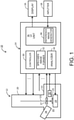
- FIG. 1 shows a charged particle beam apparatus according to an embodiment of the present disclosure.
- the charged particle beam apparatus is specifically a scanning electron microscope 10.
- the scanning electron microscope 10 may primarily be separated into a measurement unit 12 and an information processor 14.
- the information processor 14 is formed from, for example, a personal computer (PC).
- a display 16 and an inputter 18 are connected to the information processor 14.
- the measurement unit 12 comprises a lens barrel 20 and a body 21.
- An inside of the body 21 is a specimen chamber 22.
- an electron beam source, a focusing lens, a deflection scanning lens, an objective lens, or the like is provided in the lens barrel 20.
- An electron beam 23 is generated by these constituting elements.
- a specimen stage 24 is provided, and a specimen 25 is held by the specimen stage 24.
- a specimen holder holding the specimen 25 is attached to the specimen stage 24.
- the specimen stage 24 has an XYZ mechanism which moves the specimen 25 in upand-down and left-and-right directions, a rotational mechanism which rotates the specimen 25, and a tilt mechanism which inclines the specimen 25.
- a specimen inclination angle is also called a tilt angle.
- the specimen 25 has a form of, for example, a small piece, a circular disc, or the like. Alternatively, a specimen 25 having a different form may be set as a measurement target.
- a secondary electron detector 26, a back-scattered electron detector 27, and a characteristic X-ray spectrometer 28 are provided at a periphery of the specimen 25. These constituting elements are schematically represented.
- the electron beam 23 is illuminated onto the specimen 25, secondary electrons and back-scattered electrons are emitted from the specimen 25, and a characteristic X-ray is emitted from the specimen 25.
- the secondary electron detector 26 the secondary electrons emitted from the specimen 25 are detected.
- the back-scattered electron detector 27 the back-scattered electrons emitted from the specimen 25 are detected.
- the characteristic X-ray spectrometer 28 the characteristic X-ray emitted from the specimen 25 is detected.
- the characteristic X-ray spectrometer 28 is, for example, an energy-dispersive characteristic X-ray spectrometer. In place of or in addition to the energy-dispersive characteristic X-ray spectrometer, a wavelength-dispersive characteristic X-ray spectrometer may be provided. Alternatively, a detector other than those described above may be provided. Normally, the electron beam 23 is two-dimensionally scanned with respect to the specimen 25. A plurality of detection signals which are output from the secondary electron detector 26, the back-scattered electron detector 27, and the characteristic X-ray spectrometer 28 are sent to the information processor 14.
- the information processor 14 includes a processor which executes an information process, a memory which stores data and a program, or the like.
- a plurality of representative functions realized by the information processor 14 are represented by a plurality of blocks.
- the information processor 14 functions as a controller 30, a specimen image former 32, an analyzer 34, a UI (user interface) unit 36, or the like.
- the controller 30 controls operations of various devices in the measurement unit 12. With the controller 30, a plurality of operation parameters for realizing an illumination condition designated by the user are determined.
- the illumination condition includes an accelerating voltage of the electron beam 23, a tilt angle of the specimen 25, or the like.
- the accelerating voltage of the electron beam 23 may also be called a landing voltage of the electron beam 23, from the viewpoint of the specimen 25.
- the specimen image former 32 forms a two-dimensional image representing a surface or a surface layer of the specimen 25 based on a sequence of detection signals (for example, a sequence of secondary electron detection signals or a sequence of back-scattered electron detection signals) acquired by the two-dimensional scanning of the electron beam 23.
- the analyzer 34 executes a qualitative analysis and a quantitative analysis of the specimen 25 based on the detection signal which is output from the characteristic X-ray spectrometer 28.
- the analyzer 34 in particular has a function to analyze one or a plurality of elements forming the specimen and a concentration (weight concentration) of each element.
- the UI unit 36 generates a graphical user interface (GUI) image provided to the user, and receives information which is input by the user through the GUI image.
- GUI graphical user interface
- the UI unit 36 has a reference image generator 38.
- the reference image generator 38 is a module which generates a reference image.
- the reference image is an image including a figure simulating a signal generation range in the specimen and a size of the signal generation range.
- the reference image forms a relevant portion of the GUI image.
- the signal generation range is, for example, a characteristic X-ray generation range in the specimen, and is more particularly a range in which the characteristic X-ray emitted from the specimen is generated.
- the reference image may further include a figure showing another signal generation range, or a figure showing an electron penetration range (electron scattering range).
- the reference image is an image showing a cross section of the signal generation range. Alternatively, a reference image three-dimensionally representing the signal generation range may be generated.
- the reference image or the GUI image including the reference image is a support image for assisting setting of the illumination condition by the user.
- the user can determine and input the illumination condition such as the accelerating voltage through the GUI image while imagining or recognizing, through observation of the GUI image, a shape and a size of the signal generation range.
- the UI unit 36 functions as a calculating means, an image generation means, and a reception means.
- the information processor 14 has the UI unit 36, but alternatively, the UI unit 36 may be included in another information processor.
- a first information processor including the controller 30, and a second information processor including the UI unit 36 may be provided, and these information processors may cooperate with each other.
- the display 16 is formed from a liquid crystal display, an organic EL display device, or the like.
- the inputter 18 is formed from a keyboard, a pointing device, or the like. Alternatively, a display with a touch panel may be provided as the display 16 and the inputter 18.
- FIG. 2 shows a first configuration of the UI unit 36.
- a plurality of blocks shown in FIG. 2 correspond to a plurality of functions realized by software, except for an element table 46.
- a receiver 40 is a module which receives an accelerating voltage E 0 , an element S, and a tilt angle T.
- the receiver 40 has default values for these parameters.
- a default value of the accelerating voltage Eo is, for example, 5 kV.
- a default value of the element S is, for example, aluminum (Al).
- a default value of the tilt angle is, for example, 0°. These values are merely exemplary.
- the receiver 40 acquires from the controller the accelerating voltage Eo and the tilt angle T which are already set in the controller, in response to an operation of the user. That is, the receiver 40 functions as an acquisition unit. As shown by reference numerals 54 and 44, the receiver 40 has a function to receive the accelerating voltage E 0 , the element S, or the tilt angle T which is input by the user through the GUI image. As the default value of the accelerating voltage Eo, an accelerating voltage which is set in the controller may be employed. In this case, the receiver 40 automatically acquires the accelerating voltage from the controller prior to generation of the reference image.
- Information for specifying the element S received by the receiver 40, is supplied to the element table 46.
- the element table 46 forms an element database.
- element information corresponding to the element S is output from the element table 46.
- the element information includes a mass A, an atomic number Z, a density p, and a minimum excitation energy Ec.
- the minimum excitation energy differs depending on the element and an electron orbital.
- a plurality of minimum excitation energies corresponding to a plurality of characteristic X-rays may be managed.
- a characteristic X-ray generation depth calculator 48 calculates a characteristic X-ray generation depth Dx based on the accelerating voltage E 0 , the tilt angle T, and the element information. A calculation formula for this purpose will be described later. As will be described later, the characteristic X-ray generation depth Dx is a depth from a specimen surface in a direction orthogonal to the specimen surface. Thus, even when the element S does not change and the accelerating voltage Eo is a constant, the characteristic X-ray generation depth Dx changes when the tilt angle T changes.
- An image generator 50 is a module which generates the GUI image, and includes the reference image generator 38.
- the reference image includes a figure simulating the characteristic X-ray generation range, a numerical value indicating the characteristic X-ray generation depth Dx, a numerical value indicating the accelerating voltage Eo, a symbol indicating the element S, and a numerical value indicating the tilt angle T.
- the characteristic X-ray generation depth Dx is a maximum value of the characteristic X-ray generation range in the depth direction.
- a size of the figure simulating the characteristic X-ray generation range is constant regardless of the characteristic X-ray generation depth Dx.
- the numerical value indicating the characteristic X-ray generation depth Dx changes according to the characteristic X-ray generation depth Dx.
- Reference numeral 52 shows a signal which is output to the display.
- Reference numeral 54 shows a signal from the inputter.
- An accelerating voltage calculator 56 is a module which back-calculates the accelerating voltage Eo from the characteristic X-ray generation depth Dx as necessary. For the back calculation, reference is made to the element information. The back-calculated accelerating voltage E 0 is sent through the receiver 40 to the reference image generator 38, and the reference image is updated. More specifically, the numerical value indicating the accelerating voltage Eo is updated.
- the receiver 40 does not have an application function to activate the illumination condition for the generation of the reference image. Therefore, when the illumination condition such as the accelerating voltage is designated on the GUI image, it is still required to separately input, as an actual illumination condition, the designated illumination condition to the controller. This is a safety measure to make the user be more cautious in setting the illumination condition.
- the GUI image is still an image for assisting the setting of the illumination condition.
- the application function may be added to the receiver, and the illumination condition designated through the GUI image may be directly applied to the controller.
- processes to newly set the illumination condition, to check the illumination condition, and to change the illumination condition can be executed through the setting image (which does not have the reference image) for setting the illumination condition.
- a setting image is generated by the controller shown in FIG. 1 .
- users having abundant knowledge and experience for the electron beam or the scanning electron microscope may set the illumination condition on the setting image, without going through the display of the GUI image.
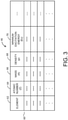
- FIG. 3 shows an example structure of the element table.
- the element table 46 is constructed on a nonvolatile memory.
- the element table 46 has a plurality of records 60 corresponding to a plurality of elements.
- Each record 60 is formed from a plurality of pieces of information corresponding to an element 62.
- These information include an atomic number 64, a mass 66, a density (weight density) 68, a minimum excitation energy 70, or the like.
- a plurality of minimum excitation energies 70 may be registered corresponding to a plurality of characteristic X-rays.
- FIG. 4 shows an operation executed when display of the GUI image is started.
- a screen 72 includes a plurality of windows 74 and 75.
- the window 74 is a main window, and a plurality of images are selectively displayed therein. These images include the setting image and the GUI image.
- a menu bar 76 includes a plurality of buttons 77a, 77b, and 77c.
- the button 77c is a button for stating up the display of the GUI image.
- the button 77c is selected with a pointer 78, and a click operation is performed, the GUI image including the reference image is displayed in the window 74.
- FIG. 5 shows a GUI image 81 of the first configuration.
- the GUI image 81 includes a reference image 82 of the first configuration.
- the GUI image 81 also includes a guidance display 120.
- the reference image 82 includes a plurality of figures 84, 90, 102, 108, and 112, a plurality of numerical values 86, 96, and 114, and a plurality of labels (test strings) 92, 98, 106, 110, and 116.
- the reference image 82 corresponds to a vertical cross section of the specimen (cross section including a trajectory of the electron beam).
- the figure 84 is a triangle, and more specifically has a downward-oriented pinnacle shape.
- the figure 84 simulates the electron beam.
- the figure 90 is a straight line simulating the specimen surface. Even when unevenness is present on the specimen surface in reality, the figure 90 is shown as a straight line. A side lower than the figure 90 corresponds to the inside of the specimen.
- An apex 104 of the figure 84 comes in contact with the figure 90.
- the apex 104 shows a point of illumination of the electron beam.
- the numerical value 86 indicates the accelerating voltage (landing voltage). Boxes 88, 94, 100, and 118 represented with broken lines indicate that the values inside the boxes are values that can be changed by the user. These boxes function as pointer recognition regions.
- the numerical value 96 indicates the tilt angle. As the tilt angle, an arbitrary numerical value within a range of 0° to 90° may be designated. This range is merely exemplary.
- the label 98 is a symbol showing the tilt
- the label 92 shows the element forming the specimen. Specifically, the label 92 is an element symbol.
- the element is designated by the user.
- a primary element or a dominating element may be designated.
- a structure may be employed in which a plurality of elements can be designated simultaneously. For example, a periodic table may be displayed, and one or a plurality of elements may be selected from the periodic table.
- the figure 102 has a liquid drop shape, and an apex thereof coincides with the apex 104.
- the figure 102 simulates the secondary electron generation range.
- the label (SE) 106 indicating the secondary electron is shown inside the figure 102.
- a size of the figure 102 is constant regardless of the accelerating voltage or the like. Alternatively, the size may be changed according to the accelerating voltage or the like.
- Two slanted sides in the liquid drop shape are slanted with respect to a horizontal axis with angles of +45° and -45°, respectively.
- the figure 108 has a liquid drop shape, and an apex thereof coincides with the apex 104.
- the figure 108 simulates the back-scattered electron generation range.
- the label (BSE) 110 showing the back-scattered electron is displayed inside the figure 108.
- a size of the figure 108 is also constant regardless of the accelerating voltage or the like. Alternatively, the size may be changed according to the accelerating voltage or the like.
- the figure 112 has a liquid drop shape, and an apex thereof coincides with the apex 104.
- the figure 112 simulates the characteristic X-ray generation range.
- the label (Characteristic X-ray) 116 showing the characteristic X-ray is displayed inside the figure 112.
- a size of the figure 112 is also constant regardless of the accelerating voltage or the like. Alternatively, the size may be changed according to the accelerating voltage or the like.
- the numerical value 114 indicating the characteristic X-ray generation depth (that is, Dx described above) is displayed. The numerical value indicates a size (a maximum value in the depth direction) of the generation range of the characteristic X-ray emitted from the specimen.
- the numerical value 114 changes with a change of the accelerating voltage, with a change of the element, or with a change of the tilt angle.
- the generation depth is displayed for one of the characteristic X-rays.
- a table for selecting a characteristic X-ray for which the generation depth is to be displayed, from among the plurality of characteristic X-rays, is prepared, and the generation depth to be displayed is selected according to the accelerating voltage by referring to this table.
- a plurality of generation depths may be displayed together.
- the guidance display 120 shows that the characteristic X-ray generation depth is being calculated from the landing voltage; that is, the accelerating voltage.
- the accelerating voltage is being calculated from the characteristic X-ray generation depth
- a different guidance display to be described below is presented.
- a paint process may be applied to the figures 102, 108, and 112.
- a configuration may be employed in which a display target figure can be arbitrarily selected from these figures.
- a configuration may be employed in which a display size of the reference image 82 can be adjusted.
- figures of shapes other than the liquid drop shape such as, for example, a circular shape, an elliptical shape, a vase shape, or the like may be employed.
- FIG. 5 when a pointer (cursor) 121 is moved close to the numerical value 86, more specifically, to a position in the box 88, and the click operation is performed, a window 122 shown in FIG. 6 is pop-up displayed.
- the window 122 includes an input field 124 for the accelerating voltage, an acquisition button 126, an OK button 128, and a cancel button 130.
- the accelerating voltage can be directly input as a numerical value using the input field 124.
- the acquisition button 126 is clicked, the accelerating voltage which is set in the controller is acquired, and is reflected in the input field 124.
- the OK button 1208 the window 122 is closed, and the accelerating voltage which is input in the input field 124 is reflected in the reference image. Specifically, the numerical value indicating the accelerating voltage is changed, and the numerical value indicating the characteristic X-ray generation depth is changed.
- a window 132 shown in FIG. 7 is pop-up displayed.
- the window 132 includes an input field 134 for the tilt angle, an acquisition button 136, an OK button 138, and a cancel button 140.
- the tilt angle can be directly input as a numerical value using the input field 134.
- the acquisition button 136 is clicked, the tilt angle which is set in the controller is acquired and reflected in the input field 134.
- the OK button 138 the window 132 is closed, and the tilt angle which is input in the input field 134 is reflected in the reference image. In this case, the form of the reference image changes, and the numerical value indicating the characteristic X-ray generation depth changes.
- FIG. 8 shows a reference image displayed when 30° is designated as the tilt angle.
- a value of "30.000°” is displayed as the numerical value 96.
- a straight line 90A showing the specimen surface is in an inclined state, with an inclination angle of 30°.
- An orientation and a position of the figure showing the electron beam are maintained.
- the mask region does not extend to the figures 102, 108, and 112, and the entirety of each of the figures 102, 108, and 112 is displayed.
- the numerical value 114 indicating the characteristic X-ray generation depth changes according to the tilt angle. A definition of the depth in the specimen inclined state will be described later in detail.
- the window 144 includes two numerical values 146 and 148 indicating the characteristic X-ray generation depths.
- the numerical value 146 indicates a generation depth of an L line
- the numerical value 148 indicates a generation depth of a K line.
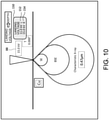
- the window 150 includes numerical values 152 and 154 indicating two landing voltages corresponding to two characteristic X-rays.
- the numerical value 152 indicates the landing voltage corresponding to the generation depth of the L line
- the numerical value 154 indicates the landing voltage corresponding to the generation depth of the K line.
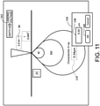
- a window 156 shown in FIG. 11 is pop-up displayed.
- the window 156 includes an input field 158 for the characteristic X-ray generation depth, an OK button 160, or the like.
- the OK button 160 is operated, an accelerating voltage corresponding to the generation depth is calculated, and the numerical value 86 is updated.
- a guidance display 162 is displayed. In this manner, the accelerating voltage can be back-calculated from the generation depth.
- a receiver 172 is a module which receives the accelerating voltage Eo, the element S, and the tilt angle T.
- the receiver 172 functions as an acquisition unit which acquires from the controller the accelerating voltage Eo, and the tilt angle T, which are set in the controller, in response to an operation of the user.
- the receiver 172 functions as an acquisition unit which acquires from the analyzer information of the element S forming the specimen.
- the concentrations of the elements may also be acquired.
- the receiver 172 has a function to receive the accelerating voltage E 0 , the element S, or the tilt angle T which is input by the user through the GUI image.
- the receiver 172 also functions as a transfer unit (application unit) which transfers, as the actual illumination condition, the received illumination condition to the controller, to apply the illumination condition; that is, to activate the illumination condition, in response to an operation of the user (refer to reference numeral 178).
- the illumination condition which is transferred is one or both of the accelerating voltage Eo and the tilt angle T.
- the information for specifying the element S which is received by the receiver 172 is supplied to the element table 180.
- the element table 180 forms an element database.
- element information corresponding to the element S is output from the element table 180.
- the element information includes the mass A, the atomic number Z, the density p, and the minimum excitation energy Ec.
- the minimum excitation energy Ec corresponds to a minimum energy for generating the characteristic X-ray.
- An electron penetration depth calculator 182 calculates an electron penetration depth D PE based on the accelerating voltage Eo, the tilt angle T, and the element information. A calculation formula for determining the electron penetration depth D PE will be described later.
- the electron penetration depth D PE is a size of an electron scattering range in the depth direction.
- the electron penetration depth calculator 182 also has a function to calculate a lateral width of the electron scattering range; that is, a width D ⁇ in a direction orthogonal to the depth axis. A calculation formula for determining the width D ⁇ of the electron scattering range will be described later.
- a back-scattered electron generation depth calculator 184 calculates the back-scattered electron generation depth D BSE based on the electron penetration depth D PE . If necessary, reference may be made to the element information for this calculation. A calculation formula for determining the back-scattered electron generation depth D BSE will be described later.
- a characteristic X-ray generation depth calculator 186 calculates the characteristic X-ray generation depth Dx based on the accelerating voltage E 0 , the tilt angle T, and the element information. A calculation formula for this calculation will be described later.
- An image generator 188 is a module which generates the GUI image, and includes a reference image generator 190.
- a reference image generator 190 To the reference image generator 190, there are supplied the electron penetration depth (depth of the electron scattering range) D PE , the width of the electron scattering range D ⁇ , the back-scattered electron generation depth D BSE , the characteristic X-ray generation depth Dx, the accelerating voltage Eo, the element S, and the tilt angle T.
- Reference numeral 192 shows a signal which is output to the display.
- Reference numeral 194 shows a signal from the inputter.
- An accelerating voltage calculator 196 is a module which back-calculates the accelerating voltage Eo from the characteristic X-ray generation depth Dx as necessary. For this back calculation, reference is made to the element information. The back-calculated accelerating voltage E 0 is sent to the receiver 172 (refer to reference numeral 198).
- A represents a mass of an atom
- Eo represents the accelerating voltage
- ⁇ represents a density of the element
- Z represents an atomic number.
- the mass A, the density p, and the atomic number Z are specified in the element table.
- the width of the electron scattering range D ⁇ is generally considered to be approximately equal to the electron penetration depth D PE .
- the characteristic X-ray generation depth Dx is calculated by the following Formula (5).
- Ec represents the minimum excitation energy for a particular electron orbital.
- D X 0.033 A E 0 1.7 ⁇ E C 1.7 ⁇ ⁇ Z
- the electron penetration depth D PE , the back-scattered electron generation depth D BSE , and the characteristic X-ray generation depth Dx are respectively multiplied by the correction coefficient k, to derive an electron penetration depth D PE ', a scattered electron generation depth D BSE ', and a characteristic X-ray generation depth Dx' in the inclined state.
- the width of the electron scattering range D ⁇ does not depend on the inclination of the specimen.
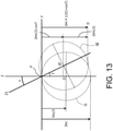
- F represents a specimen surface.
- a Z axis corresponds to an electron beam before inclination.
- the electron penetration depth is shown by D PE .
- the electron penetration depth D PE is a parameter defining a size of the electron scattering range in the specimen, and, in FIG. 13 , the electron scattering range is shown by a circle (in reality, a sphere) Q.
- An origin of the range is shown by O.
- a distance from the specimen surface to the origin O (depth on the Z-axis) is D PE /2.
- the specimen is inclined with the tilt angle T. From another perspective, the electron beam is inclined relative to the specimen.
- the electron beam after the inclination is shown by Z1.
- a position and an orientation of the specimen are fixed, and the electron beam is inclined.
- the electron scattering range after the inclination is shown by a circle Q'.
- a definition is employed defining that a distance from the specimen surface in a direction orthogonal to the specimen surface is the depth.
- the depth of an origin O' of the electron scattering range after the inclination of the specimen is (D PE /2) x cosT.
- a value obtained by adding a radius of the circle Q', D PE /2, to the depth; that is, D PE x 1/2 (1 + cosT) is the electron penetration depth after the inclination of the specimen.
- a value obtained by removing D PE from this calculation formula is the correction coefficient k described above.
- the definition is employed in which the distance from the specimen surface in a direction orthogonal to the specimen surface is the depth, with an increase in the tilt angle T, the electron penetration depth D PE , the back-scattered electron generation depth D BSE , and the characteristic X-ray generation depth Dx are respectively reduced.
- calculation formula and the model described above are merely exemplary, and another calculation formula and another model may be used.
- another calculation formula and another model may be used.
- by providing to the user a rough estimate approximately showing the shape and the size of the range of physical phenomena such as the electron scattering range, the back-scattered electron generation range, and the characteristic X-ray generation range it becomes possible to reduce the burden of the user or to assist the setting of the illumination condition by the user, as compared to the case where none of these information is provided to the user.
- FIG. 14 shows a GUI image 201 generated and displayed in the second configuration.
- the GUI image includes a reference image 202 and a guidance display 120 of the second configuration.
- elements similar to those shown in FIG. 5 are assigned the same reference numerals.
- the reference image 202 includes a plurality of figures 84, 90, 102, 108, 112, and 204, a plurality of numerical values 86, 96, 114, 206, 208, and 212, and a plurality of labels (text strings) 92, 98, 106, 110, 116, and 210.
- the reference image 202 corresponds to a vertical cross section of the specimen.
- the figure 84 has a downward-oriented pinnacle shape, and indicates the electron beam.
- the figure 90 is a straight line simulating the specimen surface.
- An apex 104 of the figure 84 comes in contact with the figure 90.
- the apex 104 shows a point of illumination of the electron beam.
- the numerical value 86 indicates the accelerating voltage (landing voltage).
- the numerical value 96 indicates the tilt angle.
- the label 98 is a symbol showing the tilt angle.
- the label 92 indicates the element forming the specimen. More specifically, the label 92 is an element symbol.
- the specimen is formed from a plurality of elements, as described above, a primary element or a dominant element is selected.
- a configuration may be employed in which a plurality of elements can be designated.
- a configuration may be employed in which a periodic table is displayed, and one or a plurality of elements are selected from the periodic table.
- the figure 102 has a liquid drop shape, and an apex thereof coincides with the apex 104.
- the figure 102 simulates the secondary electron generation range.
- the label (SE) 106 indicating the secondary electrons is displayed.
- a size of the figure 102 is constant regardless of the accelerating voltage or the like. Alternatively, the size may be changed according to the accelerating voltage or the like.
- the figure 108 has a liquid drop shape, and an apex thereof coincides with the apex 104.
- the figure 108 simulates the back-scattered electron generation range.
- the label (BSE) 110 indicating the back-scattered electron is displayed.
- the numerical value 212 indicating the back-scattered electron generation depth is displayed.
- a size of the figure 108 is constant regardless of the accelerating voltage or the like, but alternatively, similar to the above, the size may be changed according to the accelerating voltage or the like.
- the numerical value 212 changes with a change of the accelerating voltage, with a change of the element, or with a change of the tilt angle.
- the figure 112 has a liquid drop shape, and an apex thereof coincides with the apex 104.
- the figure 112 simulates the characteristic X-ray generation range.
- the label (Characteristic X-ray) 116 indicating the characteristic X-ray is displayed.
- a size of the figure 112 is also constant regardless of the accelerating voltage or the like. Alternatively, the size may be changed according to the accelerating voltage or the like.
- the numerical value 114 indicating the characteristic X-ray generation depth is displayed.
- the numerical value indicates a size (a width in the depth direction) of the generation range of the characteristic X-ray emitted from the specimen.
- the numerical value 114 changes with a change of the accelerating voltage, with a change of the element, or with a change of the tilt angle.
- the figure 204 has a liquid drop shape, and an apex thereof coincides with the apex 104.
- the figure 204 simulates the electron scattering range, and in the figure 204, the label 210 indicating the landing electron is displayed.
- a size of the figure 204 is also constant regardless of the accelerating voltage or the like. Alternatively, the size may be changed according to the accelerating voltage or the like.
- the numerical value 206 indicating a size (electron penetration depth) of the electron scattering range is displayed, and the numerical value 208 indicating the width of the electron scattering range is displayed.
- the numerical value 206 changes with a change of the accelerating voltage, with a change of the element, or with a change of the tilt angle.
- the numerical value 208 changes with a change of the accelerating voltage or with a change of the element, but does not change with a change of the tilt angle.
- the guidance display 120 indicates that the characteristic X-ray generation depth is being calculated from the landing voltage; that is, the accelerating voltage.
- a paint process is applied to the figures 102, 108, 112, and 204, and the figures are thus distinguished from each other.
- one of the figures (the figure with a smaller size) is displayed with a priority.
- a figure of a shape other than the liquid drop shape such as, for example, a circular shape, an elliptical shape, a vase shape, or the like, may alternatively be employed.
- the size relationship is reversed between a plurality of ranges, such may be displayed or one or a plurality of figures may be deleted.
- FIG. 15 shows a reference image when the specimen is inclined.
- a numerical value 96A indicate the tilt angle.
- a figure 90B showing the specimen surface is in an inclined state.
- portions protruding on the upper side in relation to the straight line is mask processed, and mask-processed figures 102A, 108A, 112A, and 204A are displayed.
- the plurality of depths shown as the plurality of numerical values are depths in the direction orthogonal to the specimen surface.
- the illumination condition may be actually applied, to execute the measurement of the specimen.
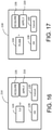
- a window 214 shown in FIG. 16 may be pop-up displayed.
- the window 214 includes, in addition to the input field 124 for accelerating voltage, the acquisition button 126, the OK button 128, and the cancel button 130, an application button 216.
- the application button 216 is operated, the accelerating voltage which is designated on the GUI image at that point is set as the actual accelerating voltage which is set in the controller.
- a window 218 shown in FIG. 17 may be pop-up displayed.
- the window 218 includes, in addition to the input field 134 for the tilt angle, the acquisition button 136, the OK button 138, and the cancel button 140, an application button 220.
- the application button 220 is operated, the tilt angle which is designated on the GUI image at that point is set as the actual tilt angle which is set in the controller.
- FIG. 18 exemplifies an animation display before the display of the reference image.
- a dynamic change of contents of the image is shown with a plurality of images 222 ⁇ 228. In reality, more images are displayed, but in FIG. 18 , some representative images 222 ⁇ 228 are shown.
- the image 222 is displayed.
- a line 232 indicating the specimen surface and a figure 230 indicating the electron beam are displayed.
- images simulating the electron scattering in the specimen are displayed.
- Each of these images is formed from a plurality of straight lines.
- straight lines may be randomly generated, and the number of the straight lines may be gradually increased, to generate an image simulating the electron scattering.
- display of such an image may be omitted.
- An animated image showing the change of the electron scattering state may be formed by actually executing a Monte Carlo simulation or the like, but because such a process requires time, a simplified animation display is instead employed.
- a reference image 238 is displayed. According to such a display, even for users with poor knowledge or little experience, it becomes easier to imagine the physical phenomenon which occurs during the measurement, and it becomes possible to visually assist the setting of the illumination condition.
- the reference image described above also may be utilized when the illumination condition which is already set is to be checked.
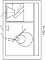
- the reference image 242 is a reference image showing the signal generation range and the electron scattering range.
- the reference image 244 is an image schematically showing the inside of the specimen chamber. More specifically, the reference image 244 is a CG image showing the specimen chamber, as viewed from a horizontal direction.
- the reference image 244 includes an object 248 indicating a lower end of the objective lens, and an object 250 indicating the specimen holder. The specimen is held by the specimen holder. The specimen holder is supported by the specimen stage, or is a part of the specimen stage.
- the specimen holder When the inclination angle of the specimen is set in the controller, the specimen holder is inclined, and the object 250 is accordingly inclined.
- the inclination angle is shown by Tx.
- Tx is designated as the inclination angle in the UI unit, or when the inclination angle Tx which is set in the controller is read to the UI unit, the reference image 242 is displayed.
- An inclination angle of a figure 246 indicating the specimen surface is Tx.
- an image other than the reference image 244 may be displayed.
- an image obtained by imaging an upper surface of the specimen holder may be displayed.
Landscapes
- Chemical & Material Sciences (AREA)
- Analytical Chemistry (AREA)
- General Health & Medical Sciences (AREA)
- Life Sciences & Earth Sciences (AREA)
- Health & Medical Sciences (AREA)
- Biochemistry (AREA)
- Physics & Mathematics (AREA)
- General Physics & Mathematics (AREA)
- Immunology (AREA)
- Pathology (AREA)
- Engineering & Computer Science (AREA)
- Computer Vision & Pattern Recognition (AREA)
- Analysing Materials By The Use Of Radiation (AREA)
Abstract
Description
- The present disclosure relates to a charged particle beam apparatus and a method of assisting setting, and in particular to a technique to assist setting of an illumination condition.
- As charged particle beam apparatuses, there are known a scanning electron microscope, an electron beam microanalyzer, an ion beam illumination apparatus, and the like. In the following, a scanning electron microscope will be described as a representative apparatus of these charged particle beam apparatuses.
- A scanning electron microscope is an apparatus in which an electron beam which is a charged particle beam is illuminated onto a specimen, and secondary electrons, back-scattered electrons, characteristic X-rays, or the like emitted from the specimen are detected. An image representing a surface or a surface layer of the specimen is formed based on a sequence of detection signals acquired by two-dimensional scanning of the electron beam. With an analysis of the characteristic X-rays emitted from the specimen, a qualitative analysis and a quantitative analysis of the specimen are executed.
- In a measurement of the specimen by the scanning electron microscope, an electron penetration depth (an electron beam penetration depth, an electron scattering depth) in the specimen changes depending on an element forming the specimen, and the electron penetration depth in the specimen also changes depending on an accelerating voltage (landing voltage) of the electron beam. Similarly, a depth in the specimen at which the back-scattered electrons are generated (a generation range of back-scattered electrons emitted from the specimen), and a depth in the specimen at which the characteristic X-rays are generated (a generation range of the characteristic X-rays emitted from the specimen) change depending on the element forming the specimen and the accelerating voltage of the electron beam.
- In the scanning electron microscope, an illumination condition such as the accelerating voltage is set by designation of a numerical value by a user. In the related art, during setting of the illumination condition, there is no display of a schematic diagram or the like for assisting a setting operation. There is also known a simulation apparatus which estimates an electron scattering range or a signal generation range in the specimen. However, such an apparatus is not a measurement apparatus, and functions as a single entity, and there has been no cooperation between such an apparatus and the charged particle beam apparatus.
-
JP 2004-163135 A JP 2006-275756 A - An advantage of the present disclosure lies in assisting the setting of the illumination condition by the user in the charged particle beam apparatus. Alternatively, an advantage of the present disclosure lies in enabling setting of the illumination condition while the user imagines a range and a size of a physical phenomenon which occurs in the specimen, in the charged particle beam apparatus.
- According to one aspect of the present disclosure, there is provided a charged particle beam apparatus comprising: a measurement unit that illuminates a charged particle beam onto a specimen, and that detects a signal emitted from the specimen; a reference image generator that generates a reference image including a figure simulating a signal generation range in the specimen and a numerical value indicating a size of the signal generation range, based on an illumination condition and specimen information for the generation of the reference image; and a display that displays a graphical user interface image including the reference image when an actual illumination condition of the charged particle beam is set.
- According to another aspect of the present disclosure, there is provided a method of assisting setting, the method comprising: generating a reference image including a figure simulating a range of a physical phenomenon in a specimen onto which an electron beam is illuminated and a numerical value indicating a size of the range of the physical phenomenon, based on an illumination condition and specimen information for the generation of the reference image; and displaying the reference image when a user sets an actual illumination condition of the electron beam.
- Embodiment(s) of the present disclosure will be described based on the following figures, wherein:
-
FIG. 1 is a conceptual diagram showing a scanning electron microscope according to an embodiment of the present disclosure; -
FIG. 2 is a diagram showing an UI (user interface) unit in a first configuration; -
FIG. 3 is a diagram showing an example of an element table; -
FIG. 4 is a diagram for explaining a display start operation: -
FIG. 5 is a diagram showing a reference image in the first configuration; -
FIG. 6 is a diagram showing a pop-up window for setting an accelerating voltage; -
FIG. 7 is a diagram showing a pop-up window for setting a tilt angle; -
FIG. 8 is a diagram showing a reference image representing an inclined state; -
FIG. 9 is a diagram showing a pop-up window for displaying a characteristic X-ray generation depth; -
FIG. 10 is a diagram showing a pop-up window for displaying an accelerating voltage; -
FIG. 11 is a diagram for explaining designation of a characteristic X-ray generation depth; -
FIG. 12 is a diagram showing a UI unit in a second configuration; -
FIG. 13 is a diagram for explaining a definition of a depth; -
FIG. 14 is a diagram showing a reference image in the second configuration; -
FIG. 15 is a diagram showing a reference image representing an inclined state; -
FIG. 16 is a diagram showing another pop-up window for setting the accelerating voltage; -
FIG. 17 is a diagram showing another pop-up window for setting the tilt angle; -
FIG. 18 is a diagram showing an animation display; and -
FIG. 19 is a diagram showing a parallel display of a plurality of reference images. - An embodiment of the present disclosure will now be described with reference to the drawings.
- A charged particle beam apparatus according to an embodiment of the present disclosure comprises a measurement unit, a reference image generator, and a display. The measurement unit illuminates a charged particle beam onto a specimen, and detects a signal emitted from the specimen. The reference image generator generates a reference image including a figure simulating a signal generation range in the specimen and a numerical value indicating a size of the signal generation range, based on an illumination condition and specimen information for the generation of the reference image. The display displays a graphical user interface image including the reference image when an actual illumination condition of the charged particle beam is set.
- According to the above-described configuration, it becomes possible for a user to set the actual illumination condition while imagining or recognizing an extent of the signal generation range in the specimen through observation of the reference image in the graphical user interface image. With this process, even a user who has only poor knowledge of the charged particle beam or the charged particle beam apparatus can appropriately set the actual illumination condition.
- In an embodiment of the present disclosure, the charged particle beam is an electron beam, and the measurement unit includes an electron beam source, a detector, or the like. As the detector, there may be exemplified a secondary electron detector, a back-scattered electron detector, a characteristic X-ray detector, or the like. The concept of the illumination condition includes an accelerating voltage, and also a specimen inclination angle. The specimen information is element information for an element forming the specimen, and, in particular, is physical information which affects an electron scattering range and the signal generation range in the specimen. The signal generation range is, for example, a generation range of the characteristic X-rays, a generation range of back-scattered electrons, or the like. Alternatively, there may be generated a reference image which includes a plurality of figures indicating a plurality of signal generation ranges, and a plurality of numerical values indicating the sizes of the plurality of signal generation ranges. Alternatively, the reference image may include a figure indicating an electron scattering range and a numerical value indicating a size of the electron scattering range.
- In an embodiment of the present disclosure, a size of the figure is maintained regardless of a change of the actual size of the signal generation range, but alternatively, the size of the figure may be changed according to the change of the actual size of the signal generation range. Even when the size of the figure is constant, the user can recognize the size of the signal generation range by a change of the numerical value accompanying the figure. In an embodiment of the present disclosure, a shape of the signal generation range in the specimen may be approximately recognized through an outer shape of the figure. However, the shape of the figure and the numerical value are merely rough estimates. Even when these information are rough estimates, the setting of the illumination condition by the user can be assisted, in comparison to the case in which no information is provided.
- A charged particle beam apparatus according to an embodiment of the present disclosure further comprises an acquisition unit, and a receiver. The acquisition unit acquires, as the illumination condition for the generation of the reference image, an illumination condition which is already set for the measurement unit. The receiver receives, as the illumination condition for the generation of the reference image, an illumination condition which is input through the graphical user interface image. The concept of the illumination condition already set in the measurement unit includes an illumination condition which is recognized and managed by a controller which controls the measurement unit.
- A charged particle beam apparatus according to an embodiment of the present disclosure further comprises an application unit. The application unit applies, to the measurement unit, as the illumination condition for the generation of the reference image, an illumination condition which is input through the graphical user interface image. Here, "application" means activation, change from a provisional setting to a nonprovisional setting, etc.
- In an embodiment of the present disclosure, the reference image changes with a change of the illumination condition for the generation of the reference image. A validity of the illumination condition after the change can be evaluated by referring to the reference image after the change, and the user can thus narrow the illumination condition to an appropriate illumination condition through such a process.
- In an embodiment of the present disclosure, the illumination condition for the generation of the reference image includes an accelerating voltage. The reference image changes with a change of the accelerating voltage. In an embodiment of the present disclosure, the illumination condition for the generation of the reference image includes a specimen inclination angle. The reference image changes with a change of the specimen inclination angle. In an embodiment of the present disclosure, the specimen information for the generation of the reference image is element information. The reference image changes with a change of the element information. In an embodiment of the present disclosure, the charged particle beam is an electron beam. The reference image includes the figure simulating a characteristic X-ray generation range as the signal generation range, and the numerical value indicating a size of the characteristic X-ray generation range. In an embodiment of the present disclosure, the reference image includes the figure simulating a back-scattered electron generation range as the signal generation range, and the numerical value indicating a size of the back-scattered electron generation range. In an embodiment of the present disclosure, the reference image includes a figure simulating an electron scattering range in the specimen, and a numerical value indicating a size of the electron scattering range. In an embodiment of the present disclosure, the reference image includes a numerical value indicating the illumination condition for the generation of the reference image. The numerical value indicating the illumination condition for the generation of the reference image changes with a change of the numerical value indicating the size of the signal generation range.
- A method of assisting according to an embodiment of the present disclosure comprises a first step and a second step. In the first step, a reference image is generated based on an illumination condition and specimen information for the generation of the reference image, which includes a figure simulating a range of a physical phenomenon in a specimen onto which an electron beam is illuminated and a numerical value indicating a size of the range of the physical phenomenon. In the second step, the reference image is displayed when a user sets an actual illumination condition of the electron beam.
- In an embodiment of the present disclosure, after the second step, an illumination condition for the generation of the reference image, which is input by the user through a graphical user interface image including the reference image, is received. Then, through a certain operation or input, the received illumination condition is set as a formal illumination condition for a measurement unit.
- The method of assisting the setting may be realized by a function of software. In this case, a program executing the method of assisting setting is installed via a network or a transportable recording medium in a charged particle beam apparatus, an information processor, or the like.
-
FIG. 1 shows a charged particle beam apparatus according to an embodiment of the present disclosure. The charged particle beam apparatus is specifically ascanning electron microscope 10. In the illustrated example configuration, thescanning electron microscope 10 may primarily be separated into ameasurement unit 12 and aninformation processor 14. Theinformation processor 14 is formed from, for example, a personal computer (PC). Adisplay 16 and aninputter 18 are connected to theinformation processor 14. - The
measurement unit 12 comprises alens barrel 20 and abody 21. An inside of thebody 21 is aspecimen chamber 22. In thelens barrel 20, an electron beam source, a focusing lens, a deflection scanning lens, an objective lens, or the like is provided. Anelectron beam 23 is generated by these constituting elements. In thespecimen chamber 22, aspecimen stage 24 is provided, and aspecimen 25 is held by thespecimen stage 24. Specifically, a specimen holder holding thespecimen 25 is attached to thespecimen stage 24. Thespecimen stage 24 has an XYZ mechanism which moves thespecimen 25 in upand-down and left-and-right directions, a rotational mechanism which rotates thespecimen 25, and a tilt mechanism which inclines thespecimen 25. A specimen inclination angle is also called a tilt angle. Thespecimen 25 has a form of, for example, a small piece, a circular disc, or the like. Alternatively, aspecimen 25 having a different form may be set as a measurement target. - In the illustrated example structure, a
secondary electron detector 26, a back-scatteredelectron detector 27, and acharacteristic X-ray spectrometer 28 are provided at a periphery of thespecimen 25. These constituting elements are schematically represented. When theelectron beam 23 is illuminated onto thespecimen 25, secondary electrons and back-scattered electrons are emitted from thespecimen 25, and a characteristic X-ray is emitted from thespecimen 25. With thesecondary electron detector 26, the secondary electrons emitted from thespecimen 25 are detected. With the back-scatteredelectron detector 27, the back-scattered electrons emitted from thespecimen 25 are detected. With thecharacteristic X-ray spectrometer 28, the characteristic X-ray emitted from thespecimen 25 is detected. - The
characteristic X-ray spectrometer 28 is, for example, an energy-dispersive characteristic X-ray spectrometer. In place of or in addition to the energy-dispersive characteristic X-ray spectrometer, a wavelength-dispersive characteristic X-ray spectrometer may be provided. Alternatively, a detector other than those described above may be provided. Normally, theelectron beam 23 is two-dimensionally scanned with respect to thespecimen 25. A plurality of detection signals which are output from thesecondary electron detector 26, the back-scatteredelectron detector 27, and thecharacteristic X-ray spectrometer 28 are sent to theinformation processor 14. - The
information processor 14 includes a processor which executes an information process, a memory which stores data and a program, or the like. InFIG. 1 , a plurality of representative functions realized by theinformation processor 14 are represented by a plurality of blocks. Specifically, theinformation processor 14 functions as acontroller 30, a specimen image former 32, ananalyzer 34, a UI (user interface)unit 36, or the like. - The
controller 30 controls operations of various devices in themeasurement unit 12. With thecontroller 30, a plurality of operation parameters for realizing an illumination condition designated by the user are determined. The illumination condition includes an accelerating voltage of theelectron beam 23, a tilt angle of thespecimen 25, or the like. The accelerating voltage of theelectron beam 23 may also be called a landing voltage of theelectron beam 23, from the viewpoint of thespecimen 25. - The specimen image former 32 forms a two-dimensional image representing a surface or a surface layer of the
specimen 25 based on a sequence of detection signals (for example, a sequence of secondary electron detection signals or a sequence of back-scattered electron detection signals) acquired by the two-dimensional scanning of theelectron beam 23. Theanalyzer 34 executes a qualitative analysis and a quantitative analysis of thespecimen 25 based on the detection signal which is output from thecharacteristic X-ray spectrometer 28. Theanalyzer 34 in particular has a function to analyze one or a plurality of elements forming the specimen and a concentration (weight concentration) of each element. - The
UI unit 36 generates a graphical user interface (GUI) image provided to the user, and receives information which is input by the user through the GUI image. TheUI unit 36 has areference image generator 38. - The
reference image generator 38 is a module which generates a reference image. The reference image is an image including a figure simulating a signal generation range in the specimen and a size of the signal generation range. The reference image forms a relevant portion of the GUI image. The signal generation range is, for example, a characteristic X-ray generation range in the specimen, and is more particularly a range in which the characteristic X-ray emitted from the specimen is generated. The reference image may further include a figure showing another signal generation range, or a figure showing an electron penetration range (electron scattering range). The reference image is an image showing a cross section of the signal generation range. Alternatively, a reference image three-dimensionally representing the signal generation range may be generated. - The reference image or the GUI image including the reference image is a support image for assisting setting of the illumination condition by the user. The user can determine and input the illumination condition such as the accelerating voltage through the GUI image while imagining or recognizing, through observation of the GUI image, a shape and a size of the signal generation range. As described, the
UI unit 36 functions as a calculating means, an image generation means, and a reception means. - In the example structure illustrated in
FIG. 1 , theinformation processor 14 has theUI unit 36, but alternatively, theUI unit 36 may be included in another information processor. For example, a first information processor including thecontroller 30, and a second information processor including theUI unit 36 may be provided, and these information processors may cooperate with each other. - The
display 16 is formed from a liquid crystal display, an organic EL display device, or the like. Theinputter 18 is formed from a keyboard, a pointing device, or the like. Alternatively, a display with a touch panel may be provided as thedisplay 16 and theinputter 18. -
FIG. 2 shows a first configuration of theUI unit 36. A plurality of blocks shown inFIG. 2 correspond to a plurality of functions realized by software, except for an element table 46. Areceiver 40 is a module which receives an accelerating voltage E0, an element S, and a tilt angle T. Thereceiver 40 has default values for these parameters. A default value of the accelerating voltage Eo is, for example, 5 kV. A default value of the element S is, for example, aluminum (Al). A default value of the tilt angle is, for example, 0°. These values are merely exemplary. - As shown by
reference numeral 42, thereceiver 40 acquires from the controller the accelerating voltage Eo and the tilt angle T which are already set in the controller, in response to an operation of the user. That is, thereceiver 40 functions as an acquisition unit. As shown byreference numerals receiver 40 has a function to receive the accelerating voltage E0, the element S, or the tilt angle T which is input by the user through the GUI image. As the default value of the accelerating voltage Eo, an accelerating voltage which is set in the controller may be employed. In this case, thereceiver 40 automatically acquires the accelerating voltage from the controller prior to generation of the reference image. - Information for specifying the element S, received by the
receiver 40, is supplied to the element table 46. The element table 46 forms an element database. When the information for specifying the element S is supplied to the element table 46, element information corresponding to the element S is output from the element table 46. The element information includes a mass A, an atomic number Z, a density p, and a minimum excitation energy Ec. The minimum excitation energy differs depending on the element and an electron orbital. In the element table 46, a plurality of minimum excitation energies corresponding to a plurality of characteristic X-rays may be managed. - A characteristic X-ray
generation depth calculator 48 calculates a characteristic X-ray generation depth Dx based on the accelerating voltage E0, the tilt angle T, and the element information. A calculation formula for this purpose will be described later. As will be described later, the characteristic X-ray generation depth Dx is a depth from a specimen surface in a direction orthogonal to the specimen surface. Thus, even when the element S does not change and the accelerating voltage Eo is a constant, the characteristic X-ray generation depth Dx changes when the tilt angle T changes. - An
image generator 50 is a module which generates the GUI image, and includes thereference image generator 38. To thereference image generator 38, the characteristic X-ray generation depth Dx, the accelerating voltage E0, the element S, and the tilt angle T are supplied. The reference image includes a figure simulating the characteristic X-ray generation range, a numerical value indicating the characteristic X-ray generation depth Dx, a numerical value indicating the accelerating voltage Eo, a symbol indicating the element S, and a numerical value indicating the tilt angle T. The characteristic X-ray generation depth Dx is a maximum value of the characteristic X-ray generation range in the depth direction. - In the present embodiment, a size of the figure simulating the characteristic X-ray generation range is constant regardless of the characteristic X-ray generation depth Dx. On the other hand, the numerical value indicating the characteristic X-ray generation depth Dx changes according to the characteristic X-ray generation depth Dx. As will be described later, with a change of the tilt angle, a size of a cut portion in each figure (a portion to be masked) changes.
Reference numeral 52 shows a signal which is output to the display.Reference numeral 54 shows a signal from the inputter. - An accelerating
voltage calculator 56 is a module which back-calculates the accelerating voltage Eo from the characteristic X-ray generation depth Dx as necessary. For the back calculation, reference is made to the element information. The back-calculated accelerating voltage E0 is sent through thereceiver 40 to thereference image generator 38, and the reference image is updated. More specifically, the numerical value indicating the accelerating voltage Eo is updated. - In the example structure illustrated in
FIG. 2 , thereceiver 40 does not have an application function to activate the illumination condition for the generation of the reference image. Therefore, when the illumination condition such as the accelerating voltage is designated on the GUI image, it is still required to separately input, as an actual illumination condition, the designated illumination condition to the controller. This is a safety measure to make the user be more cautious in setting the illumination condition. In this case also, the GUI image is still an image for assisting the setting of the illumination condition. Alternatively, as will be described later, the application function may be added to the receiver, and the illumination condition designated through the GUI image may be directly applied to the controller. - Similar to the related art, processes to newly set the illumination condition, to check the illumination condition, and to change the illumination condition can be executed through the setting image (which does not have the reference image) for setting the illumination condition. Such a setting image is generated by the controller shown in
FIG. 1 . For example, users having abundant knowledge and experience for the electron beam or the scanning electron microscope may set the illumination condition on the setting image, without going through the display of the GUI image. -
FIG. 3 shows an example structure of the element table. The element table 46 is constructed on a nonvolatile memory. The element table 46 has a plurality ofrecords 60 corresponding to a plurality of elements. Eachrecord 60 is formed from a plurality of pieces of information corresponding to anelement 62. These information include anatomic number 64, amass 66, a density (weight density) 68, aminimum excitation energy 70, or the like. As described above, a plurality ofminimum excitation energies 70 may be registered corresponding to a plurality of characteristic X-rays. -
FIG. 4 shows an operation executed when display of the GUI image is started. Ascreen 72 includes a plurality ofwindows window 74 is a main window, and a plurality of images are selectively displayed therein. These images include the setting image and the GUI image. - A
menu bar 76 includes a plurality ofbuttons button 77c is a button for stating up the display of the GUI image. When thebutton 77c is selected with apointer 78, and a click operation is performed, the GUI image including the reference image is displayed in thewindow 74. -
FIG. 5 shows aGUI image 81 of the first configuration. TheGUI image 81 includes areference image 82 of the first configuration. In the illustrated example, theGUI image 81 also includes aguidance display 120. Thereference image 82 includes a plurality of figures 84, 90, 102, 108, and 112, a plurality ofnumerical values reference image 82 corresponds to a vertical cross section of the specimen (cross section including a trajectory of the electron beam). - The figure 84 is a triangle, and more specifically has a downward-oriented pinnacle shape. The figure 84 simulates the electron beam. The figure 90 is a straight line simulating the specimen surface. Even when unevenness is present on the specimen surface in reality, the figure 90 is shown as a straight line. A side lower than the figure 90 corresponds to the inside of the specimen. An apex 104 of the figure 84 comes in contact with the figure 90. The apex 104 shows a point of illumination of the electron beam. The
numerical value 86 indicates the accelerating voltage (landing voltage).Boxes numerical value 96 indicates the tilt angle. As the tilt angle, an arbitrary numerical value within a range of 0° to 90° may be designated. This range is merely exemplary. Thelabel 98 is a symbol showing the tilt angle. - The
label 92 shows the element forming the specimen. Specifically, thelabel 92 is an element symbol. The element is designated by the user. When the specimen is formed from a plurality of elements, a primary element or a dominating element may be designated. Alternatively, a structure may be employed in which a plurality of elements can be designated simultaneously. For example, a periodic table may be displayed, and one or a plurality of elements may be selected from the periodic table. - The figure 102 has a liquid drop shape, and an apex thereof coincides with the apex 104. The figure 102 simulates the secondary electron generation range. The label (SE) 106 indicating the secondary electron is shown inside the figure 102. A size of the figure 102 is constant regardless of the accelerating voltage or the like. Alternatively, the size may be changed according to the accelerating voltage or the like. Two slanted sides in the liquid drop shape are slanted with respect to a horizontal axis with angles of +45° and -45°, respectively.
- The figure 108 has a liquid drop shape, and an apex thereof coincides with the apex 104. The figure 108 simulates the back-scattered electron generation range. The label (BSE) 110 showing the back-scattered electron is displayed inside the figure 108. A size of the figure 108 is also constant regardless of the accelerating voltage or the like. Alternatively, the size may be changed according to the accelerating voltage or the like.
- The figure 112 has a liquid drop shape, and an apex thereof coincides with the apex 104. The figure 112 simulates the characteristic X-ray generation range. The label (Characteristic X-ray) 116 showing the characteristic X-ray is displayed inside the figure 112. A size of the figure 112 is also constant regardless of the accelerating voltage or the like. Alternatively, the size may be changed according to the accelerating voltage or the like. Inside the figure 112, the
numerical value 114 indicating the characteristic X-ray generation depth (that is, Dx described above) is displayed. The numerical value indicates a size (a maximum value in the depth direction) of the generation range of the characteristic X-ray emitted from the specimen. Thenumerical value 114 changes with a change of the accelerating voltage, with a change of the element, or with a change of the tilt angle. When a plurality of characteristic X-rays are generated, the generation depth is displayed for one of the characteristic X-rays. In the present embodiment, according to the accelerating voltage, a table for selecting a characteristic X-ray for which the generation depth is to be displayed, from among the plurality of characteristic X-rays, is prepared, and the generation depth to be displayed is selected according to the accelerating voltage by referring to this table. Alternatively, a plurality of generation depths may be displayed together. - The
guidance display 120 shows that the characteristic X-ray generation depth is being calculated from the landing voltage; that is, the accelerating voltage. On the other hand, when the accelerating voltage is being calculated from the characteristic X-ray generation depth, a different guidance display to be described below is presented. - A paint process may be applied to the figures 102, 108, and 112. Alternatively, a configuration may be employed in which a display target figure can be arbitrarily selected from these figures. Alternatively, a configuration may be employed in which a display size of the
reference image 82 can be adjusted. Alternatively, as the shape of the figures 102, 108, and 112, figures of shapes other than the liquid drop shape such as, for example, a circular shape, an elliptical shape, a vase shape, or the like may be employed. - In
FIG. 5 , when a pointer (cursor) 121 is moved close to thenumerical value 86, more specifically, to a position in thebox 88, and the click operation is performed, awindow 122 shown inFIG. 6 is pop-up displayed. - In
FIG. 6 , thewindow 122 includes aninput field 124 for the accelerating voltage, anacquisition button 126, anOK button 128, and a cancelbutton 130. The accelerating voltage can be directly input as a numerical value using theinput field 124. When theacquisition button 126 is clicked, the accelerating voltage which is set in the controller is acquired, and is reflected in theinput field 124. With clicking of theOK button 128, thewindow 122 is closed, and the accelerating voltage which is input in theinput field 124 is reflected in the reference image. Specifically, the numerical value indicating the accelerating voltage is changed, and the numerical value indicating the characteristic X-ray generation depth is changed. - In
FIG. 5 , when thepointer 121 is moved to a position inside thebox 100 and the click operation is performed, awindow 132 shown inFIG. 7 is pop-up displayed. Thewindow 132 includes aninput field 134 for the tilt angle, anacquisition button 136, anOK button 138, and a cancelbutton 140. The tilt angle can be directly input as a numerical value using theinput field 134. When theacquisition button 136 is clicked, the tilt angle which is set in the controller is acquired and reflected in theinput field 134. With clicking of theOK button 138, thewindow 132 is closed, and the tilt angle which is input in theinput field 134 is reflected in the reference image. In this case, the form of the reference image changes, and the numerical value indicating the characteristic X-ray generation depth changes. -
FIG. 8 shows a reference image displayed when 30° is designated as the tilt angle. A value of "30.000°" is displayed as thenumerical value 96. Astraight line 90A showing the specimen surface is in an inclined state, with an inclination angle of 30°. An orientation and a position of the figure showing the electron beam are maintained. In the example display shown inFIG. 8 , the mask region does not extend to the figures 102, 108, and 112, and the entirety of each of the figures 102, 108, and 112 is displayed. Thenumerical value 114 indicating the characteristic X-ray generation depth changes according to the tilt angle. A definition of the depth in the specimen inclined state will be described later in detail. - In
FIG. 5 , when thepointer 121 is moved to a position inside the box 114 (no click operation is necessary), awindow 144 shown inFIG. 9 is automatically pop-up displayed. InFIG. 9 , thewindow 144 includes twonumerical values numerical value 146 indicates a generation depth of an L line, and thenumerical value 148 indicates a generation depth of a K line. With this configuration, it becomes possible to recognize the generation depth of each characteristic X-ray when a plurality of the characteristic X-rays are generated. Although the reference image includes only onenumerical value 114, alternatively, the reference image may include a plurality of numerical values indicating a plurality of generation depths. According to the present embodiment, the content of the reference image can be simplified. - In
FIG. 5 , when thepointer 121 is moved to a position inside the box 88 (no click operation is necessary), awindow 150 shown inFIG. 10 is automatically pop-up displayed. InFIG. 10 , thewindow 150 includesnumerical values numerical value 152 indicates the landing voltage corresponding to the generation depth of the L line, and thenumerical value 154 indicates the landing voltage corresponding to the generation depth of the K line. With this configuration, for elements for which a plurality of characteristic X-rays are generated, it becomes possible to recognize the accelerating voltage to be designated when observation of a particular characteristic X-ray is desired. Although the reference image includes only the numerical value indicating one accelerating voltage, alternatively, a plurality of numerical values indicating a plurality of accelerating voltages may be displayed together in the reference image. According to the present embodiment, the content of the reference image can be simplified. - In
FIG. 5 , when thepointer 121 is moved to a position inside thebox 118 and a click operation is performed in this state, awindow 156 shown inFIG. 11 is pop-up displayed. InFIG. 11 , thewindow 156 includes aninput field 158 for the characteristic X-ray generation depth, anOK button 160, or the like. When the generation depth is directly input using theinput field 158, and theOK button 160 is operated, an accelerating voltage corresponding to the generation depth is calculated, and thenumerical value 86 is updated. In this case, aguidance display 162 is displayed. In this manner, the accelerating voltage can be back-calculated from the generation depth. - Next, a second configuration of the UI unit will be described with reference to figures from
FIG. 12 and on. A plurality of blocks shown inFIG. 12 show functions realized by software, except for an element table 180. Areceiver 172 is a module which receives the accelerating voltage Eo, the element S, and the tilt angle T. - As shown by
reference numeral 176, thereceiver 172 functions as an acquisition unit which acquires from the controller the accelerating voltage Eo, and the tilt angle T, which are set in the controller, in response to an operation of the user. In addition, thereceiver 172 functions as an acquisition unit which acquires from the analyzer information of the element S forming the specimen. When the specimen is formed from a plurality of elements, the concentrations of the elements may also be acquired. As shown byreference numerals receiver 172 has a function to receive the accelerating voltage E0, the element S, or the tilt angle T which is input by the user through the GUI image. - The
receiver 172 also functions as a transfer unit (application unit) which transfers, as the actual illumination condition, the received illumination condition to the controller, to apply the illumination condition; that is, to activate the illumination condition, in response to an operation of the user (refer to reference numeral 178). The illumination condition which is transferred is one or both of the accelerating voltage Eo and the tilt angle T. - The information for specifying the element S which is received by the
receiver 172 is supplied to the element table 180. The element table 180 forms an element database. When the information for specifying the element S is supplied to the element table 180, element information corresponding to the element S is output from the element table 180. The element information includes the mass A, the atomic number Z, the density p, and the minimum excitation energy Ec. The minimum excitation energy Ec corresponds to a minimum energy for generating the characteristic X-ray. - An electron
penetration depth calculator 182 calculates an electron penetration depth DPE based on the accelerating voltage Eo, the tilt angle T, and the element information. A calculation formula for determining the electron penetration depth DPE will be described later. The electron penetration depth DPE is a size of an electron scattering range in the depth direction. The electronpenetration depth calculator 182 also has a function to calculate a lateral width of the electron scattering range; that is, a width Dϕ in a direction orthogonal to the depth axis. A calculation formula for determining the width Dϕ of the electron scattering range will be described later. - In the present embodiment, a back-scattered electron
generation depth calculator 184 calculates the back-scattered electron generation depth DBSE based on the electron penetration depth DPE. If necessary, reference may be made to the element information for this calculation. A calculation formula for determining the back-scattered electron generation depth DBSE will be described later. A characteristic X-raygeneration depth calculator 186 calculates the characteristic X-ray generation depth Dx based on the accelerating voltage E0, the tilt angle T, and the element information. A calculation formula for this calculation will be described later. - An
image generator 188 is a module which generates the GUI image, and includes areference image generator 190. To thereference image generator 190, there are supplied the electron penetration depth (depth of the electron scattering range) DPE, the width of the electron scattering range Dϕ, the back-scattered electron generation depth DBSE, the characteristic X-ray generation depth Dx, the accelerating voltage Eo, the element S, and the tilt angle T. Reference numeral 192 shows a signal which is output to the display.Reference numeral 194 shows a signal from the inputter. - An accelerating
voltage calculator 196 is a module which back-calculates the accelerating voltage Eo from the characteristic X-ray generation depth Dx as necessary. For this back calculation, reference is made to the element information. The back-calculated accelerating voltage E0 is sent to the receiver 172 (refer to reference numeral 198). - Calculation methods will now be described for the electron penetration depth DPE, the width of the electron scattering range Dϕ, the back-scattered electron generation depth DBSE, and the characteristic X-ray generation depth Dx.
- First, it is assumed that the specimen is not inclined. The electron penetration depth DPE is calculated through the following Formula (1) which is known in the art.
[Formula 1]
- In Formula (1) described above, A represents a mass of an atom, Eo represents the accelerating voltage, ρ represents a density of the element, and Z represents an atomic number. Alternatively, the electron penetration depth DPE may be calculated by following Formula (2) which is known in the art.
[Formula 2]
- The mass A, the density p, and the atomic number Z are specified in the element table. The width of the electron scattering range Dϕ is generally considered to be approximately equal to the electron penetration depth DPE. The following Formula (3) shows this relationship.
[Formula 3]
- The back-scattered electron generation depth DBSE is calculated by following Formula (4). Specifically, the back-scattered electron generation depth DBSE is calculated from the electron penetration depth DPE, and as a half of the electron penetration depth DPE.
[Formula 4]
- The characteristic X-ray generation depth Dx is calculated by the following Formula (5). In the following, Ec represents the minimum excitation energy for a particular electron orbital.
[Formula 5]
- When the accelerating voltage Eo is to be back-calculated from the characteristic X-ray generation depth Dx, the following Formula (6), which is another form of Formula (5), may be utilized.
[Formula 6]
- On the other hand, when the specimen is inclined by the tilt angle T, a correction coefficient k defined by the following Formula (7) is used.
[Formula 7]
- More specifically, the electron penetration depth DPE, the back-scattered electron generation depth DBSE, and the characteristic X-ray generation depth Dx are respectively multiplied by the correction coefficient k, to derive an electron penetration depth DPE', a scattered electron generation depth DBSE', and a characteristic X-ray generation depth Dx' in the inclined state. When the following model is to be employed, the width of the electron scattering range Dϕ does not depend on the inclination of the specimen.
- Definition of the depth and the correction coefficient will now be described in detail with reference to
FIG. 13 . InFIG. 13 , F represents a specimen surface. A Z axis corresponds to an electron beam before inclination. The electron penetration depth is shown by DPE. The electron penetration depth DPE is a parameter defining a size of the electron scattering range in the specimen, and, inFIG. 13 , the electron scattering range is shown by a circle (in reality, a sphere) Q. An origin of the range is shown by O. A distance from the specimen surface to the origin O (depth on the Z-axis) is DPE/2. - The specimen is inclined with the tilt angle T. From another perspective, the electron beam is inclined relative to the specimen. The electron beam after the inclination is shown by Z1. In this manner, in
FIG. 13 , for the purpose of explanation, a position and an orientation of the specimen are fixed, and the electron beam is inclined. The electron scattering range after the inclination is shown by a circle Q'. - In the present embodiment, a definition is employed defining that a distance from the specimen surface in a direction orthogonal to the specimen surface is the depth. When this definition is employed, the depth of an origin O' of the electron scattering range after the inclination of the specimen is (DPE/2) x cosT. A value obtained by adding a radius of the circle Q', DPE/2, to the depth; that is, DPE x 1/2 (1 + cosT), is the electron penetration depth after the inclination of the specimen. A value obtained by removing DPE from this calculation formula is the correction coefficient k described above.
- Because the definition is employed in which the distance from the specimen surface in a direction orthogonal to the specimen surface is the depth, with an increase in the tilt angle T, the electron penetration depth DPE, the back-scattered electron generation depth DBSE, and the characteristic X-ray generation depth Dx are respectively reduced.
- The calculation formula and the model described above are merely exemplary, and another calculation formula and another model may be used. In any case, by providing to the user a rough estimate approximately showing the shape and the size of the range of physical phenomena such as the electron scattering range, the back-scattered electron generation range, and the characteristic X-ray generation range, it becomes possible to reduce the burden of the user or to assist the setting of the illumination condition by the user, as compared to the case where none of these information is provided to the user.
-
FIG. 14 shows aGUI image 201 generated and displayed in the second configuration. The GUI image includes areference image 202 and aguidance display 120 of the second configuration. InFIG. 14 , elements similar to those shown inFIG. 5 are assigned the same reference numerals. - The
reference image 202 includes a plurality of figures 84, 90, 102, 108, 112, and 204, a plurality ofnumerical values reference image 202 corresponds to a vertical cross section of the specimen. - The figure 84 has a downward-oriented pinnacle shape, and indicates the electron beam. The figure 90 is a straight line simulating the specimen surface. An apex 104 of the figure 84 comes in contact with the figure 90. The apex 104 shows a point of illumination of the electron beam. The
numerical value 86 indicates the accelerating voltage (landing voltage). Thenumerical value 96 indicates the tilt angle. Thelabel 98 is a symbol showing the tilt angle. - The
label 92 indicates the element forming the specimen. More specifically, thelabel 92 is an element symbol. When the specimen is formed from a plurality of elements, as described above, a primary element or a dominant element is selected. Alternatively, a configuration may be employed in which a plurality of elements can be designated. For example, a configuration may be employed in which a periodic table is displayed, and one or a plurality of elements are selected from the periodic table. - The figure 102 has a liquid drop shape, and an apex thereof coincides with the apex 104. The figure 102 simulates the secondary electron generation range. In the figure 102, the label (SE) 106 indicating the secondary electrons is displayed. A size of the figure 102 is constant regardless of the accelerating voltage or the like. Alternatively, the size may be changed according to the accelerating voltage or the like.
- The figure 108 has a liquid drop shape, and an apex thereof coincides with the apex 104. The figure 108 simulates the back-scattered electron generation range. In the figure 108, the label (BSE) 110 indicating the back-scattered electron is displayed. In addition, the
numerical value 212 indicating the back-scattered electron generation depth is displayed. A size of the figure 108 is constant regardless of the accelerating voltage or the like, but alternatively, similar to the above, the size may be changed according to the accelerating voltage or the like. Thenumerical value 212 changes with a change of the accelerating voltage, with a change of the element, or with a change of the tilt angle. - The figure 112 has a liquid drop shape, and an apex thereof coincides with the apex 104. The figure 112 simulates the characteristic X-ray generation range. In the figure 112, the label (Characteristic X-ray) 116 indicating the characteristic X-ray is displayed. A size of the figure 112 is also constant regardless of the accelerating voltage or the like. Alternatively, the size may be changed according to the accelerating voltage or the like. In the figure 112, the
numerical value 114 indicating the characteristic X-ray generation depth is displayed. The numerical value indicates a size (a width in the depth direction) of the generation range of the characteristic X-ray emitted from the specimen. Thenumerical value 114 changes with a change of the accelerating voltage, with a change of the element, or with a change of the tilt angle. - The figure 204 has a liquid drop shape, and an apex thereof coincides with the apex 104. The figure 204 simulates the electron scattering range, and in the figure 204, the
label 210 indicating the landing electron is displayed. A size of the figure 204 is also constant regardless of the accelerating voltage or the like. Alternatively, the size may be changed according to the accelerating voltage or the like. - In the figure 204, the
numerical value 206 indicating a size (electron penetration depth) of the electron scattering range is displayed, and thenumerical value 208 indicating the width of the electron scattering range is displayed. Thenumerical value 206 changes with a change of the accelerating voltage, with a change of the element, or with a change of the tilt angle. Thenumerical value 208 changes with a change of the accelerating voltage or with a change of the element, but does not change with a change of the tilt angle. - The
guidance display 120 indicates that the characteristic X-ray generation depth is being calculated from the landing voltage; that is, the accelerating voltage. - A paint process is applied to the figures 102, 108, 112, and 204, and the figures are thus distinguished from each other. In overlapping regions of the figures 102, 108, 112, and 204, one of the figures (the figure with a smaller size) is displayed with a priority. As the shapes of the figures 102, 108, 112, and 204, a figure of a shape other than the liquid drop shape such as, for example, a circular shape, an elliptical shape, a vase shape, or the like, may alternatively be employed. When the size relationship is reversed between a plurality of ranges, such may be displayed or one or a plurality of figures may be deleted.
-
FIG. 15 shows a reference image when the specimen is inclined. Anumerical value 96A indicate the tilt angle. A figure 90B showing the specimen surface is in an inclined state. In the plurality of original figures, portions protruding on the upper side in relation to the straight line is mask processed, and mask-processed figures 102A, 108A, 112A, and 204A are displayed. As described above, the plurality of depths shown as the plurality of numerical values are depths in the direction orthogonal to the specimen surface. - It is possible to change the accelerating voltage or the tilt angle while observing the reference image, and to consequently determine an optimum illumination condition in relation to the specimen. Then, the illumination condition may be actually applied, to execute the measurement of the specimen.
- When the second configuration is employed, on the GUI image, for example, when a box including the accelerating voltage is clicked, a
window 214 shown inFIG. 16 may be pop-up displayed. Thewindow 214 includes, in addition to theinput field 124 for accelerating voltage, theacquisition button 126, theOK button 128, and the cancelbutton 130, anapplication button 216. When theapplication button 216 is operated, the accelerating voltage which is designated on the GUI image at that point is set as the actual accelerating voltage which is set in the controller. - When the second configuration is employed, on the GUI image, for example, when a box including the tilt angle is clicked, a
window 218 shown inFIG. 17 may be pop-up displayed. Thewindow 218 includes, in addition to theinput field 134 for the tilt angle, theacquisition button 136, theOK button 138, and the cancelbutton 140, anapplication button 220. When theapplication button 220 is operated, the tilt angle which is designated on the GUI image at that point is set as the actual tilt angle which is set in the controller. -
FIG. 18 exemplifies an animation display before the display of the reference image. A dynamic change of contents of the image is shown with a plurality ofimages 222 ∼ 228. In reality, more images are displayed, but inFIG. 18 , somerepresentative images 222 ∼ 228 are shown. - First, the
image 222 is displayed. In theimage 222, aline 232 indicating the specimen surface and a figure 230 indicating the electron beam are displayed. Then, as shown by animage 224 and animage 226, images simulating the electron scattering in the specimen are displayed. Each of these images is formed from a plurality of straight lines. For example, as shown byreference numerals image 222, display of such an image may be omitted. - An animated image showing the change of the electron scattering state may be formed by actually executing a Monte Carlo simulation or the like, but because such a process requires time, a simplified animation display is instead employed. Immediately after the animation display is completed, a
reference image 238 is displayed. According to such a display, even for users with poor knowledge or little experience, it becomes easier to imagine the physical phenomenon which occurs during the measurement, and it becomes possible to visually assist the setting of the illumination condition. The reference image described above also may be utilized when the illumination condition which is already set is to be checked. - As shown in
FIG. 19 , a plurality ofreference images reference image 242 is a reference image showing the signal generation range and the electron scattering range. Thereference image 244 is an image schematically showing the inside of the specimen chamber. More specifically, thereference image 244 is a CG image showing the specimen chamber, as viewed from a horizontal direction. Thereference image 244 includes anobject 248 indicating a lower end of the objective lens, and anobject 250 indicating the specimen holder. The specimen is held by the specimen holder. The specimen holder is supported by the specimen stage, or is a part of the specimen stage. - When the inclination angle of the specimen is set in the controller, the specimen holder is inclined, and the
object 250 is accordingly inclined. The inclination angle is shown by Tx. On the other hand, when Tx is designated as the inclination angle in the UI unit, or when the inclination angle Tx which is set in the controller is read to the UI unit, thereference image 242 is displayed. An inclination angle of a figure 246 indicating the specimen surface is Tx. With a simultaneous observation of the tworeference images - As the image to be displayed along with the
reference image 242, an image other than thereference image 244 may be displayed. For example, an image obtained by imaging an upper surface of the specimen holder may be displayed. - In the above-described embodiment, the scanning electron microscope has been described, but alternatively, the above-described structures may be applied to other charged particle beam apparatuses.
Claims (11)
- A charged particle beam apparatus comprising:a measurement unit (12) that illuminates a charged particle beam onto a specimen (25), and that detects a signal emitted from the specimen (25);a reference image generator (38, 190) that generates a reference image (82, 202) including a figure simulating a signal generation range in the specimen (25) and a numerical value (114, 212, 206, 208) indicating a size of the signal generation range, based on an illumination condition and specimen information for the generation of the reference image; anda display (16) that displays a graphical user interface image (81, 201) including the reference image (82, 202) when an actual illumination condition of the charged particle beam is set.
- The charged particle beam apparatus according to claim 1, further comprising:an acquisition unit (40, 172) that acquires, as the illumination condition for the generation of the reference image, an illumination condition which is already set for the measurement unit (12); anda receiver (40, 172) that receives, as the illumination condition for the generation of the reference image, an illumination condition which is input through the graphical user interface image.
- The charged particle beam apparatus according to claim 1, further comprising:
an application unit (172) that applies, to the measurement unit (12), as the illumination condition for the generation of the reference image, an illumination condition which is input through the graphical user interface image (81, 201). - The charged particle beam apparatus according to claim 1, whereinthe illumination condition for the generation of the reference image includes an accelerating voltage, andthe reference image (82, 202) changes with a change of the accelerating voltage.
- The charged particle beam apparatus according to claim 1, whereinthe illumination condition for the generation of the reference image includes a specimen inclination angle, andthe reference image (82, 202) changes with a change of the specimen inclination angle.
- The charged particle beam apparatus according to claim 1, whereinthe specimen information for the generation of the reference image is element information, andthe reference image (82, 202) changes with a change of the element information.
- The charged particle beam apparatus according to claim 1, whereinthe charged particle beam is an electron beam, andthe reference image (82, 202) includes the figure (112) simulating a characteristic X-ray generation range as the signal generation range, and the numerical value (114) indicating a size of the characteristic X-ray generation range.
- The charged particle beam apparatus according to claim 1, wherein
the reference image (202) includes the figure (108) simulating a back-scattered electron generation range as the signal generation range, and the numerical value (212) indicating a size of the back-scattered electron generation range. - The charged particle beam apparatus according to claim 1, wherein
the reference image (202) includes a figure (204) simulating an electron scattering range in the specimen, and a numerical value (206, 208) indicating a size of the electron scattering range. - The charged particle beam apparatus according to claim 1, whereinthe reference image (82, 202) includes a numerical value (86, 96) indicating the illumination condition for the generation of the reference image, andthe numerical value (86, 96) indicating the illumination condition for the generation of the reference image changes with a change of the numerical value (114) indicating the size of the signal generation range.
- A method of assisting setting, the method comprising:generating a reference image (82, 202) including a figure (108, 112, 204) simulating a range of a physical phenomenon in a specimen (25) onto which an electron beam is illuminated and a numerical value (114, 212, 206, 208) indicating a size of the range of the physical phenomenon, based on an illumination condition and specimen information for the generation of the reference image; anddisplaying the reference image (82, 202) when a user sets an actual illumination condition of the electron beam.
Applications Claiming Priority (1)
| Application Number | Priority Date | Filing Date | Title |
|---|---|---|---|
| JP2020124582A JP7160870B2 (en) | 2020-07-21 | 2020-07-21 | Charged particle beam device and setting support method |
Publications (1)
| Publication Number | Publication Date |
|---|---|
| EP3944284A1 true EP3944284A1 (en) | 2022-01-26 |
Family
ID=76971738
Family Applications (1)
| Application Number | Title | Priority Date | Filing Date |
|---|---|---|---|
| EP21186404.6A Pending EP3944284A1 (en) | 2020-07-21 | 2021-07-19 | Charged particle beam apparatus and setting assisting method |
Country Status (4)
| Country | Link |
|---|---|
| US (1) | US11557458B2 (en) |
| EP (1) | EP3944284A1 (en) |
| JP (1) | JP7160870B2 (en) |
| CN (1) | CN114088758A (en) |
Families Citing this family (1)
| Publication number | Priority date | Publication date | Assignee | Title |
|---|---|---|---|---|
| JP7160871B2 (en) * | 2020-07-21 | 2022-10-25 | 日本電子株式会社 | Charged particle beam device and setting support method |
Citations (2)
| Publication number | Priority date | Publication date | Assignee | Title |
|---|---|---|---|---|
| JP2004163135A (en) | 2002-11-11 | 2004-06-10 | Jeol Ltd | X-ray analyzer |
| JP2006275756A (en) | 2005-03-29 | 2006-10-12 | Jeol Ltd | X-ray analyzer with electronic excitation |
Family Cites Families (13)
| Publication number | Priority date | Publication date | Assignee | Title |
|---|---|---|---|---|
| JPH0231146A (en) * | 1988-07-19 | 1990-02-01 | Shimadzu Corp | Method for estimating positional resolving power of electron beam microanalyzer |
| JP4517323B2 (en) | 2000-07-19 | 2010-08-04 | 株式会社島津製作所 | Electron microanalyzer measurement data correction method |
| JP3950619B2 (en) | 2000-08-21 | 2007-08-01 | 日本電子株式会社 | Surface analysis data display method in surface analyzer using electron beam |
| JP3914784B2 (en) | 2002-02-19 | 2007-05-16 | 日本電子株式会社 | X-ray image processing method |
| JP3934461B2 (en) * | 2002-04-11 | 2007-06-20 | 株式会社キーエンス | Method for preventing charge-up of electron microscope and electron microscope |
| DE10229407B4 (en) * | 2002-06-29 | 2021-10-14 | Leica Microsystems Cms Gmbh | Procedure for setting the system parameters of a scanning microscope and scanning microscope |
| JP3993817B2 (en) | 2002-12-11 | 2007-10-17 | 株式会社日立製作所 | Defect composition analysis method and apparatus |
| JP2008177064A (en) | 2007-01-19 | 2008-07-31 | Hitachi High-Technologies Corp | Scanning charged particle microscope apparatus and method for processing images acquired by scanning charged particle microscope apparatus |
| WO2017158744A1 (en) * | 2016-03-16 | 2017-09-21 | 株式会社 日立ハイテクノロジーズ | Defect inspection method and defect inspection device |
| EP3240013B1 (en) * | 2016-04-26 | 2018-11-07 | FEI Company | Three-dimensional imaging in charged-particle microscopy |
| JP6823563B2 (en) * | 2017-07-31 | 2021-02-03 | 株式会社日立製作所 | Scanning electron microscope and image processing equipment |
| JP6865465B2 (en) * | 2017-11-10 | 2021-04-28 | 株式会社日立ハイテク | Pattern measuring device and measuring method |
| JP7199290B2 (en) * | 2019-04-08 | 2023-01-05 | 株式会社日立ハイテク | Pattern cross-sectional shape estimation system and program |
-
2020
- 2020-07-21 JP JP2020124582A patent/JP7160870B2/en active Active
-
2021
- 2021-07-19 EP EP21186404.6A patent/EP3944284A1/en active Pending
- 2021-07-20 US US17/380,095 patent/US11557458B2/en active Active
- 2021-07-20 CN CN202110817170.9A patent/CN114088758A/en active Pending
Patent Citations (2)
| Publication number | Priority date | Publication date | Assignee | Title |
|---|---|---|---|---|
| JP2004163135A (en) | 2002-11-11 | 2004-06-10 | Jeol Ltd | X-ray analyzer |
| JP2006275756A (en) | 2005-03-29 | 2006-10-12 | Jeol Ltd | X-ray analyzer with electronic excitation |
Non-Patent Citations (4)
| Title |
|---|
| BROOKS C R ET AL: "The application of scanning electron microscopy to fractography", MATERIALS CHARACTERIZATION, ELSEVIER, NEW YORK, NY, US, vol. 33, no. 3, 1 October 1994 (1994-10-01), pages 195 - 243, XP024205313, ISSN: 1044-5803, [retrieved on 19941001], DOI: 10.1016/1044-5803(94)90045-0 * |
| KRUMEICH FRANK: "Contents 1. The Electron and its Properties Properties of Electrons, their Interactions with Matter and Applications in Electron Microscopy", 1 January 2015 (2015-01-01), XP055870667, Retrieved from the Internet <URL:https://www.microscopy.ethz.ch/downloads/Interactions.pdf> [retrieved on 20211208] * |
| SHARON LEE ET AL: "Studies on Electron Penetration Versus Beam Acceleration Voltage in Energy-Dispersive X-Ray Microanalysis", SEMICONDUCTOR ELECTRONICS, 2006. ICSE '06. IEEE INTERNATIONAL CONFEREN CE ON, IEEE, PI, 1 November 2006 (2006-11-01), pages 610 - 613, XP031113277, ISBN: 978-0-7803-9730-9 * |
| ZHAO HONG ET AL: "QUANTITATIVE BACKSCATTERED ELECTRON ANALYSIS TECHNIQUES FOR CEMENT -BASED MATERIALS", 1 June 1990 (1990-06-01), Lawrence, Kansas (US), pages 1 - 56, XP055873047, Retrieved from the Internet <URL:https://citeseerx.ist.psu.edu/viewdoc/download?doi=10.1.1.690.3323&rep=rep1&type=pdf> * |
Also Published As
| Publication number | Publication date |
|---|---|
| US11557458B2 (en) | 2023-01-17 |
| CN114088758A (en) | 2022-02-25 |
| JP2022021150A (en) | 2022-02-02 |
| JP7160870B2 (en) | 2022-10-25 |
| US20220028653A1 (en) | 2022-01-27 |
Similar Documents
| Publication | Publication Date | Title |
|---|---|---|
| JP6099900B2 (en) | Visualization by charged particle microscope | |
| JP6261178B2 (en) | Charged particle beam device, sample processing method using charged particle beam device, and sample processing computer program using charged particle beam device | |
| JP2021097039A (en) | Improvement method of transmission kikuchi diffraction pattern | |
| EP3518271A1 (en) | Scanning electron microscope and measurement method | |
| US11557458B2 (en) | Charged particle beam apparatus and setting assisting method | |
| JP2002039976A (en) | Correction method of measurement data of electron beam micro analyzer | |
| JP5187810B2 (en) | Film thickness measuring method and sample preparation method, film thickness measuring apparatus and sample preparation apparatus | |
| JP7018365B2 (en) | Charged particle beam device and analysis method | |
| JP6336881B2 (en) | Scatter diagram display device, scatter diagram display method, and surface analysis device | |
| US11587761B2 (en) | Charged particle beam apparatus and setting assisting method | |
| US11600463B2 (en) | Cross-section observation device, and control method | |
| US11574795B2 (en) | Charged particle beam apparatus and setting assisting method | |
| US11682539B2 (en) | Charged particle beam apparatus and setting assisting method | |
| US11282670B1 (en) | Slice depth reconstruction of charged particle images using model simulation for improved generation of 3D sample images | |
| JP6573736B1 (en) | 3D image generation apparatus and coefficient calculation method for 3D image generation apparatus | |
| EP3246696B1 (en) | Operation guide system for x-ray analysis, operation guide method therefor, and operation guide program therefor | |
| JP7083629B2 (en) | Quantitative analysis method and electron microscope | |
| RU2329490C1 (en) | Method of generating image of surface topography and device for its implementation | |
| JP6598205B2 (en) | Nondestructive inspection method and apparatus | |
| JP2006275756A (en) | X-ray analyzer with electronic excitation | |
| JP4498817B2 (en) | Element concentration measuring device | |
| JP7238366B2 (en) | Analysis system | |
| WO2026009504A1 (en) | Analysis data generation apparatus, analysis data generation method, and analysis data generation program | |
| CN120141999A (en) | Cloud image processing method, system and medium for free fall penetration soil deformation measurement | |
| Hájková | Pattern recognition, classification and simulation of laser beam impact: technical report no. DCSE/TR-2008-03 |
Legal Events
| Date | Code | Title | Description |
|---|---|---|---|
| PUAI | Public reference made under article 153(3) epc to a published international application that has entered the european phase |
Free format text: ORIGINAL CODE: 0009012 |
|
| STAA | Information on the status of an ep patent application or granted ep patent |
Free format text: STATUS: THE APPLICATION HAS BEEN PUBLISHED |
|
| AK | Designated contracting states |
Kind code of ref document: A1 Designated state(s): AL AT BE BG CH CY CZ DE DK EE ES FI FR GB GR HR HU IE IS IT LI LT LU LV MC MK MT NL NO PL PT RO RS SE SI SK SM TR |
|
| STAA | Information on the status of an ep patent application or granted ep patent |
Free format text: STATUS: REQUEST FOR EXAMINATION WAS MADE |
|
| 17P | Request for examination filed |
Effective date: 20220706 |
|
| RBV | Designated contracting states (corrected) |
Designated state(s): AL AT BE BG CH CY CZ DE DK EE ES FI FR GB GR HR HU IE IS IT LI LT LU LV MC MK MT NL NO PL PT RO RS SE SI SK SM TR |