EP3943967A1 - Calibration system, and calibration support frame for same - Google Patents
Calibration system, and calibration support frame for same Download PDFInfo
- Publication number
- EP3943967A1 EP3943967A1 EP20773704.0A EP20773704A EP3943967A1 EP 3943967 A1 EP3943967 A1 EP 3943967A1 EP 20773704 A EP20773704 A EP 20773704A EP 3943967 A1 EP3943967 A1 EP 3943967A1
- Authority
- EP
- European Patent Office
- Prior art keywords
- vertical rod
- threaded
- rotating member
- fixed
- threaded rotating
- Prior art date
- Legal status (The legal status is an assumption and is not a legal conclusion. Google has not performed a legal analysis and makes no representation as to the accuracy of the status listed.)
- Granted
Links
Images











Classifications
-
- F—MECHANICAL ENGINEERING; LIGHTING; HEATING; WEAPONS; BLASTING
- F16—ENGINEERING ELEMENTS AND UNITS; GENERAL MEASURES FOR PRODUCING AND MAINTAINING EFFECTIVE FUNCTIONING OF MACHINES OR INSTALLATIONS; THERMAL INSULATION IN GENERAL
- F16M—FRAMES, CASINGS OR BEDS OF ENGINES, MACHINES OR APPARATUS, NOT SPECIFIC TO ENGINES, MACHINES OR APPARATUS PROVIDED FOR ELSEWHERE; STANDS; SUPPORTS
- F16M11/00—Stands or trestles as supports for apparatus or articles placed thereon ; Stands for scientific apparatus such as gravitational force meters
- F16M11/02—Heads
- F16M11/04—Means for attachment of apparatus; Means allowing adjustment of the apparatus relatively to the stand
- F16M11/043—Allowing translations
- F16M11/045—Allowing translations adapted to left-right translation movement
-
- F—MECHANICAL ENGINEERING; LIGHTING; HEATING; WEAPONS; BLASTING
- F16—ENGINEERING ELEMENTS AND UNITS; GENERAL MEASURES FOR PRODUCING AND MAINTAINING EFFECTIVE FUNCTIONING OF MACHINES OR INSTALLATIONS; THERMAL INSULATION IN GENERAL
- F16M—FRAMES, CASINGS OR BEDS OF ENGINES, MACHINES OR APPARATUS, NOT SPECIFIC TO ENGINES, MACHINES OR APPARATUS PROVIDED FOR ELSEWHERE; STANDS; SUPPORTS
- F16M11/00—Stands or trestles as supports for apparatus or articles placed thereon ; Stands for scientific apparatus such as gravitational force meters
- F16M11/02—Heads
- F16M11/18—Heads with mechanism for moving the apparatus relatively to the stand
-
- F—MECHANICAL ENGINEERING; LIGHTING; HEATING; WEAPONS; BLASTING
- F16—ENGINEERING ELEMENTS AND UNITS; GENERAL MEASURES FOR PRODUCING AND MAINTAINING EFFECTIVE FUNCTIONING OF MACHINES OR INSTALLATIONS; THERMAL INSULATION IN GENERAL
- F16M—FRAMES, CASINGS OR BEDS OF ENGINES, MACHINES OR APPARATUS, NOT SPECIFIC TO ENGINES, MACHINES OR APPARATUS PROVIDED FOR ELSEWHERE; STANDS; SUPPORTS
- F16M11/00—Stands or trestles as supports for apparatus or articles placed thereon ; Stands for scientific apparatus such as gravitational force meters
- F16M11/02—Heads
- F16M11/04—Means for attachment of apparatus; Means allowing adjustment of the apparatus relatively to the stand
- F16M11/041—Allowing quick release of the apparatus
-
- F—MECHANICAL ENGINEERING; LIGHTING; HEATING; WEAPONS; BLASTING
- F16—ENGINEERING ELEMENTS AND UNITS; GENERAL MEASURES FOR PRODUCING AND MAINTAINING EFFECTIVE FUNCTIONING OF MACHINES OR INSTALLATIONS; THERMAL INSULATION IN GENERAL
- F16M—FRAMES, CASINGS OR BEDS OF ENGINES, MACHINES OR APPARATUS, NOT SPECIFIC TO ENGINES, MACHINES OR APPARATUS PROVIDED FOR ELSEWHERE; STANDS; SUPPORTS
- F16M11/00—Stands or trestles as supports for apparatus or articles placed thereon ; Stands for scientific apparatus such as gravitational force meters
- F16M11/02—Heads
- F16M11/04—Means for attachment of apparatus; Means allowing adjustment of the apparatus relatively to the stand
- F16M11/043—Allowing translations
- F16M11/046—Allowing translations adapted to upward-downward translation movement
-
- F—MECHANICAL ENGINEERING; LIGHTING; HEATING; WEAPONS; BLASTING
- F16—ENGINEERING ELEMENTS AND UNITS; GENERAL MEASURES FOR PRODUCING AND MAINTAINING EFFECTIVE FUNCTIONING OF MACHINES OR INSTALLATIONS; THERMAL INSULATION IN GENERAL
- F16M—FRAMES, CASINGS OR BEDS OF ENGINES, MACHINES OR APPARATUS, NOT SPECIFIC TO ENGINES, MACHINES OR APPARATUS PROVIDED FOR ELSEWHERE; STANDS; SUPPORTS
- F16M11/00—Stands or trestles as supports for apparatus or articles placed thereon ; Stands for scientific apparatus such as gravitational force meters
- F16M11/02—Heads
- F16M11/04—Means for attachment of apparatus; Means allowing adjustment of the apparatus relatively to the stand
- F16M11/06—Means for attachment of apparatus; Means allowing adjustment of the apparatus relatively to the stand allowing pivoting
- F16M11/08—Means for attachment of apparatus; Means allowing adjustment of the apparatus relatively to the stand allowing pivoting around a vertical axis, e.g. panoramic heads
-
- F—MECHANICAL ENGINEERING; LIGHTING; HEATING; WEAPONS; BLASTING
- F16—ENGINEERING ELEMENTS AND UNITS; GENERAL MEASURES FOR PRODUCING AND MAINTAINING EFFECTIVE FUNCTIONING OF MACHINES OR INSTALLATIONS; THERMAL INSULATION IN GENERAL
- F16M—FRAMES, CASINGS OR BEDS OF ENGINES, MACHINES OR APPARATUS, NOT SPECIFIC TO ENGINES, MACHINES OR APPARATUS PROVIDED FOR ELSEWHERE; STANDS; SUPPORTS
- F16M11/00—Stands or trestles as supports for apparatus or articles placed thereon ; Stands for scientific apparatus such as gravitational force meters
- F16M11/20—Undercarriages with or without wheels
- F16M11/24—Undercarriages with or without wheels changeable in height or length of legs, also for transport only, e.g. by means of tubes screwed into each other
- F16M11/26—Undercarriages with or without wheels changeable in height or length of legs, also for transport only, e.g. by means of tubes screwed into each other by telescoping, with or without folding
-
- F—MECHANICAL ENGINEERING; LIGHTING; HEATING; WEAPONS; BLASTING
- F16—ENGINEERING ELEMENTS AND UNITS; GENERAL MEASURES FOR PRODUCING AND MAINTAINING EFFECTIVE FUNCTIONING OF MACHINES OR INSTALLATIONS; THERMAL INSULATION IN GENERAL
- F16M—FRAMES, CASINGS OR BEDS OF ENGINES, MACHINES OR APPARATUS, NOT SPECIFIC TO ENGINES, MACHINES OR APPARATUS PROVIDED FOR ELSEWHERE; STANDS; SUPPORTS
- F16M11/00—Stands or trestles as supports for apparatus or articles placed thereon ; Stands for scientific apparatus such as gravitational force meters
- F16M11/20—Undercarriages with or without wheels
- F16M11/24—Undercarriages with or without wheels changeable in height or length of legs, also for transport only, e.g. by means of tubes screwed into each other
- F16M11/26—Undercarriages with or without wheels changeable in height or length of legs, also for transport only, e.g. by means of tubes screwed into each other by telescoping, with or without folding
- F16M11/28—Undercarriages for supports with one single telescoping pillar
-
- F—MECHANICAL ENGINEERING; LIGHTING; HEATING; WEAPONS; BLASTING
- F16—ENGINEERING ELEMENTS AND UNITS; GENERAL MEASURES FOR PRODUCING AND MAINTAINING EFFECTIVE FUNCTIONING OF MACHINES OR INSTALLATIONS; THERMAL INSULATION IN GENERAL
- F16M—FRAMES, CASINGS OR BEDS OF ENGINES, MACHINES OR APPARATUS, NOT SPECIFIC TO ENGINES, MACHINES OR APPARATUS PROVIDED FOR ELSEWHERE; STANDS; SUPPORTS
- F16M11/00—Stands or trestles as supports for apparatus or articles placed thereon ; Stands for scientific apparatus such as gravitational force meters
- F16M11/20—Undercarriages with or without wheels
- F16M11/24—Undercarriages with or without wheels changeable in height or length of legs, also for transport only, e.g. by means of tubes screwed into each other
- F16M11/38—Undercarriages with or without wheels changeable in height or length of legs, also for transport only, e.g. by means of tubes screwed into each other by folding, e.g. pivoting or scissors tong mechanisms
-
- F—MECHANICAL ENGINEERING; LIGHTING; HEATING; WEAPONS; BLASTING
- F16—ENGINEERING ELEMENTS AND UNITS; GENERAL MEASURES FOR PRODUCING AND MAINTAINING EFFECTIVE FUNCTIONING OF MACHINES OR INSTALLATIONS; THERMAL INSULATION IN GENERAL
- F16M—FRAMES, CASINGS OR BEDS OF ENGINES, MACHINES OR APPARATUS, NOT SPECIFIC TO ENGINES, MACHINES OR APPARATUS PROVIDED FOR ELSEWHERE; STANDS; SUPPORTS
- F16M11/00—Stands or trestles as supports for apparatus or articles placed thereon ; Stands for scientific apparatus such as gravitational force meters
- F16M11/42—Stands or trestles as supports for apparatus or articles placed thereon ; Stands for scientific apparatus such as gravitational force meters with arrangement for propelling the support stands on wheels
-
- G—PHYSICS
- G01—MEASURING; TESTING
- G01D—MEASURING NOT SPECIALLY ADAPTED FOR A SPECIFIC VARIABLE; ARRANGEMENTS FOR MEASURING TWO OR MORE VARIABLES NOT COVERED IN A SINGLE OTHER SUBCLASS; TARIFF METERING APPARATUS; MEASURING OR TESTING NOT OTHERWISE PROVIDED FOR
- G01D18/00—Testing or calibrating apparatus or arrangements provided for in groups G01D1/00 - G01D15/00
-
- G—PHYSICS
- G01—MEASURING; TESTING
- G01S—RADIO DIRECTION-FINDING; RADIO NAVIGATION; DETERMINING DISTANCE OR VELOCITY BY USE OF RADIO WAVES; LOCATING OR PRESENCE-DETECTING BY USE OF THE REFLECTION OR RERADIATION OF RADIO WAVES; ANALOGOUS ARRANGEMENTS USING OTHER WAVES
- G01S7/00—Details of systems according to groups G01S13/00, G01S15/00, G01S17/00
- G01S7/02—Details of systems according to groups G01S13/00, G01S15/00, G01S17/00 of systems according to group G01S13/00
- G01S7/027—Constructional details of housings, e.g. form, type, material or ruggedness
-
- G—PHYSICS
- G01—MEASURING; TESTING
- G01S—RADIO DIRECTION-FINDING; RADIO NAVIGATION; DETERMINING DISTANCE OR VELOCITY BY USE OF RADIO WAVES; LOCATING OR PRESENCE-DETECTING BY USE OF THE REFLECTION OR RERADIATION OF RADIO WAVES; ANALOGOUS ARRANGEMENTS USING OTHER WAVES
- G01S7/00—Details of systems according to groups G01S13/00, G01S15/00, G01S17/00
- G01S7/02—Details of systems according to groups G01S13/00, G01S15/00, G01S17/00 of systems according to group G01S13/00
- G01S7/40—Means for monitoring or calibrating
-
- G—PHYSICS
- G01—MEASURING; TESTING
- G01S—RADIO DIRECTION-FINDING; RADIO NAVIGATION; DETERMINING DISTANCE OR VELOCITY BY USE OF RADIO WAVES; LOCATING OR PRESENCE-DETECTING BY USE OF THE REFLECTION OR RERADIATION OF RADIO WAVES; ANALOGOUS ARRANGEMENTS USING OTHER WAVES
- G01S7/00—Details of systems according to groups G01S13/00, G01S15/00, G01S17/00
- G01S7/02—Details of systems according to groups G01S13/00, G01S15/00, G01S17/00 of systems according to group G01S13/00
- G01S7/40—Means for monitoring or calibrating
- G01S7/4052—Means for monitoring or calibrating by simulation of echoes
- G01S7/4082—Means for monitoring or calibrating by simulation of echoes using externally generated reference signals, e.g. via remote reflector or transponder
- G01S7/4086—Means for monitoring or calibrating by simulation of echoes using externally generated reference signals, e.g. via remote reflector or transponder in a calibrating environment, e.g. anechoic chamber
Definitions
- the present application relates to the technical field of vehicle maintenance and device calibration, and in particular, to a calibration system and a calibration bracket thereof.
- An advanced driver assistant system is an active security technology of collecting environmental data inside and outside a vehicle at the prime time by using various sensors mounted to the vehicle to perform technical processing such as identification, detection, and tracking of static and dynamic objects, enabling a driver to perceive a potential danger as quickly as possible, thereby attracting attention and improving security.
- Sensors adopted in the ADAS mainly include a camera, a radar, a laser, and an ultrasonic wave, which can detect light, heat, pressure, or other variables for monitoring status of a vehicle, and are generally located on front and rear bumpers, on a side mirror, inside a steering column, or on a windscreen of the vehicle.
- vibration, collision, environmental temperature and humidity, and the like change physical mounting states of the foregoing sensors, and therefore irregular correction or calibration is required.
- Embodiments of the present invention are intended to provide a calibration system and a calibration bracket thereof, which can resolve the technical problem in the prior art that a calibration bracket has relatively large volumes and is difficult to move.
- the embodiments of the present invention adopt the following technical solution to resolve the technical problem.
- a calibration bracket including a base, a stand assembly and a support assembly, the support assembly being configured to mount a calibration element, the stand assembly including: a fixed vertical rod, one end of the fixed vertical rod being mounted to the base; a movable vertical rod mounted to an other end of the fixed vertical rod, the movable vertical rod being movable relative to the fixed vertical rod only along a central axis, and the support assembly being mounted to the movable vertical rod; a driving mechanism, including a first threaded rotating member, a second threaded rotating member and a threaded fixed member, the first threaded rotating member being mounted to the fixed vertical rod and being rotatable relative to the fixed vertical rod only about the central axis, the second threaded rotating member having a first threaded structure and a second threaded structure spiraling about the central axis, a spiraling direction of the first threaded structure being the same as a spiraling direction of the second threaded structure, the second threaded rotating member being
- the first threaded rotating member is inserted in the second threaded rotating member, and the first threaded structure is disposed in the second threaded rotating member.
- the first threaded rotating member includes a first screw portion and a first limiting portion, the first limiting portion being disposed at an end of the first screw portion.
- the second threaded rotating member has a first screw hole and a first accommodating groove, the first screw hole being in communication with the first accommodating groove.
- the first threaded structure is disposed on a hole wall of the first screw hole. The first screw portion is inserted in the first screw hole, and the first limiting portion is accommodated in the first accommodating groove. A cross-sectional dimension of the first limiting portion is greater than a cross-sectional dimension of the first screw portion.
- the second threaded rotating member is inserted in the first threaded rotating member, and the first threaded structure is disposed outside the second threaded rotating member.
- the second threaded rotating member is inserted in the threaded fixed member, and the second threaded structure is disposed outside the second threaded rotating member.
- the second threaded rotating member includes a second screw portion and a second limiting portion, the second limiting portion being disposed at an end of the second screw portion.
- the threaded fixed member has a second screw hole and a second accommodating groove, the second screw hole being in communication with the second accommodating groove.
- the second threaded structure is disposed on a hole wall of the second screw hole. The second screw portion is inserted in the second screw hole, and the second limiting portion is accommodated in the second accommodating groove. A cross-sectional dimension of the second limiting portion is greater than a cross-sectional dimension of the second screw portion.
- the threaded fixed member is disposed in the second threaded rotating member
- the second threaded structure is disposed in the second threaded rotating member
- the driving mechanism further includes a hand wheel configured to drive the first threaded rotating member to rotate.
- the driving mechanism further includes a first helical gear and a second helical gear, the first helical gear being fixedly mounted to the first threaded rotating member, and an axis of rotation of the first helical gear overlapping the central axis.
- the second helical gear is mounted to the fixed vertical rod, the second helical gear is rotatable relative to the fixed vertical rod about its axis of rotation, and an axis of rotation of the second helical gear is perpendicular to the central axis.
- the first helical gear is meshed with the second helical gear.
- the fixed vertical rod has a mounting separator plate.
- the first threaded rotating member includes the first screw portion and a journal portion, the journal portion being disposed at the end of the first screw portion.
- the journal portion is inserted in the mounting separator plate, and the cross-sectional dimension of the first screw portion is greater than a cross-sectional dimension of the journal portion, so that the first threaded rotating member is rotatable relative to the fixed vertical rod only about the central axis.
- the movable vertical rod is inserted in the fixed vertical rod, so that the movable vertical rod is movable relative to the fixed vertical rod along the central axis.
- cross-sections of both the movable vertical rod and the fixed vertical rod are non-circular.
- the movable vertical rod includes an inner rod portion and an outer rod portion, the inner rod portion being inserted in the outer rod portion, the outer rod portion being inserted in the fixed vertical rod, and the threaded fixed member being fixedly mounted to the inner rod portion.
- the outer rod portion has a second sliding groove and a second snap-fit opening, the second sliding groove being in communication with the second snap-fit opening.
- the inner rod portion has a second stop portion, a cross-sectional dimension of the inner rod portion being less than a cross-sectional dimension of the second stop portion. The second stop portion is inserted in the second sliding groove, and the inner rod portion is inserted in the second snap-fit opening.
- the fixed vertical rod includes a fixed vertical rod body and a foldable vertical rod portion.
- One end of the fixed vertical rod body is mounted to the base, an other end of the fixed vertical rod body is mounted to the foldable vertical rod portion, and the foldable vertical rod portion is pivotably rotatable relative to the fixed vertical rod body.
- the movable vertical rod is mounted to the foldable vertical rod portion and is movable relative to the foldable vertical rod portion along the central axis.
- the first threaded rotating member is mounted to the foldable vertical rod portion and is rotatable relative to the foldable vertical rod portion only about the central axis.
- the fixed vertical rod has a first sliding groove and a first snap-fit opening.
- the first sliding groove is in communication with the first snap-fit opening.
- the movable vertical rod has a first stop portion, a cross-sectional dimension of the movable vertical rod being less than a cross-sectional dimension of the first stop portion. The first stop portion is inserted in the first sliding groove, and the movable vertical rod is inserted in the first snap-fit opening.
- the support assembly is mounted to a top of the movable vertical rod.
- a calibration system including a calibration element and the foregoing calibration bracket, where the calibration element may be hung on the calibration bracket.
- the first threaded rotating member rotates relative to the fixed vertical rod, which can drive the second threaded rotating member, the threaded fixed member, and the movable vertical rod to move in the direction of the fixed vertical rod together, so that the volume of the calibration bracket is reduced, facilitating removal of the calibration bracket.
- the present invention is described in more detail below with reference to the accompanying drawings and specific embodiments. It should be noted that, when a component is expressed as “being fixed to” another component, the component may be directly on the another component, or one or more intermediate components may exist between the component and the another component. When one component is expressed as “being connected to” another component, the component may be directly connected to the another component, or one or more intermediate components may exist between the component and the another component.
- orientation or position relationships indicated by terms such as “up”, “down”, “inside”, “outside”, “vertical”, and “horizontal” are based on orientation or position relationships shown in the accompanying drawings, and are merely used for ease of description of the present invention and for brevity of description, rather than indicating or implying that the mentioned apparatus or element needs to have a particular orientation or needs to be constructed and operated in a particular orientation, and therefore should not be understood as a limitation on the present invention.
- terms “first” and “second” are merely used for description and should not be understood as indicating or implying relative importance.
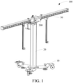
- a calibration bracket 100 provided in an embodiment of the present invention includes a base 10, a stand assembly 20 and a support assembly 30.
- the stand assembly 20 is fixedly connected to the base 10.
- the support assembly 30 includes a first beam portion 32, a second beam portion 34 and a connecting portion 36.
- the connecting portion 36 is mounted to the stand assembly 20.
- One end of the connecting portion 36 is hinged to the first beam portion 32, and the other end of the connecting portion 36 is hinged to the second beam portion 34.
- the first beam portion 32 and the second beam portion 34 can respectively rotate toward each other relative to the connecting portion 36, to fold the support assembly 30.
- the first beam portion 32 and the second beam portion 34 can also respectively rotate away from each other relative to the connecting portion 36, to unfold the support assembly 30.
- the "mounting” includes fixed mounting such as welding mounting as well as detachable mounting.
- the support assembly 30 may be configured to hang a calibration element, for example, a multi-line laser 200, a calibration target, a radar reflection or absorption apparatus, and the like, to calibrate a vehicle-mounted driver assistant system.
- a calibration element for example, a multi-line laser 200, a calibration target, a radar reflection or absorption apparatus, and the like.
- the first beam portion 32 and the second beam portion 34 can pivotally rotate relative to the connecting portion 36, respectively, to fold the support assembly 30, so that a volume of the calibration bracket 100 can be reduced to facilitate shipment.
- the first beam portion 32, the second beam portion 34 and the connecting portion 36 constitute a beam.
- the support assembly is mounted on the top surface of a movable vertical rod.
- a center of gravity of the support assembly is closer to a center of gravity of the vertical rod compared with a traditional calibration bracket, so that stability of the calibration bracket can be improved and a base with a smaller area can be used.
- first beam portion 32 and the second beam portion 34 can rotate toward each other relative to the connecting portion 36, for example, which can be folded together downward, upward, forward, and backward.
- a length of the connecting portion 36 can be relatively short, and the first beam portion 32 and the second beam portion 34 are in a drooping state. In this way, the support assembly 30 does not need to be removed from the stand assembly 20, and space occupied by the calibration bracket 100 will be significantly reduced, which can be carried conveniently in vehicles.
- the length of the connecting portion 36 can be made relatively long, so that the first beam portion 32 and the second beam portion 34 can be placed close to the connecting portion 36 after being folded and can be fixed to the connecting portion 36 by using a releasable fixing device.
- the support assembly 30 may be removed from the stand assembly 20 and then mounted to the stand assembly 20 after being carried to a required place.
- the manner of folding the support assembly 30 is not limited to the foregoing manners.
- the beam may be folded into two ends, and there is no connecting portion 36 at this time.
- the beam may also be folded into four or more sections. However, three sections are preferred, because in this case a middle section of the beam has no fracture. In this way, the beam can be stably fixed onto the vertical rod by using only one fastening component at the middle section.
- the base 10 includes a base body 12, a roller 14, a height adjustment member 16 and a pull ring 18.
- the base body 12 has a triangular claw shape and includes three claws extending in three different directions.
- the base body 12 may be made of a metal material.
- the roller 14 is mounted to a bottom surface of the base body 12, and there may be three rollers 14. Each of the rollers 14 is mounted to an end of a corresponding one of the claws to facilitate movement of the base body 12. In this embodiment, the roller 14 is an omni-directional moving roller, so that the base body 12 can move toward any direction.
- the height adjustment member 16 is mounted to the base body 12 for adjusting a height of the base body 12.
- the height adjustment member 16 is an adjustment knob, and there are three height adjustment members.
- Each of the height adjustment members 16 is mounted to a corresponding one of the claws and is close to a corresponding one of the rollers 14, and the three height adjustment members 16 are distributed in a regular triangle.
- the pull ring 18 can be mounted to an upper surface of one of the claws to facilitate pulling of the calibration bracket 100.
- a shape of the base body 12 may vary according to an actual requirement, and is not limited to a triangle claw shape.
- the base body 12 may be a rectangle or a circle.
- the number of rollers 14 and height adjustment members 16 can be increased or decreased according to actual needs.
- the triangular-claw-shaped base body 12 may be provided with two height adjustment members and mated with a foot with a fixed height, to adjust the angle of the base body 12.
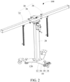
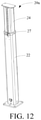
- the stand assembly 20 may include a fixed vertical rod 22, a movable vertical rod 24 and a driving mechanism 26.
- the movable vertical rod 24 is sleeved in the fixed vertical rod 22, and can move along a length direction of the fixed vertical rod 22 relative to the fixed vertical rod 22.
- the driving mechanism 26 is mounted to the fixed vertical rod 22 for driving the movable vertical rod 24 to move along the length direction of the fixed vertical rod 22 relative to the fixed vertical rod 22.
- a height of the stand assembly 20 can be reduced to nearly half of an original height.
- the cross bar assembly 30 is folded, so that the stand assembly 20 can be very suitable to be carried in a trunk of a transportation means such as a vehicle.
- the fixed vertical rod may also be used as an inner rod and the movable vertical rod as an outer rod as required.
- the driving mechanism 26 is mounted to the fixed vertical rod 22 and configured to drive the movable vertical rod 24 to move in the length direction of the fixed vertical rod 22 relative to the fixed vertical rod 22.
- the fixed vertical rod 22 and the movable vertical rod 24 are square tubes.
- the movable vertical rod 24 is closely sleeved in the fixed vertical rod 22, so that the movable vertical rod 24 can move only in the length direction of the fixed vertical rod 22 relative to the fixed vertical rod 22, and the movable vertical rod 24 can be prevented from moving in other directions relative to the fixed vertical rod 22.
- This configuration is very important for the calibration bracket 100 to be foldable, because during the calibration, a fixed relative position relationship between components of the calibration bracket 100 is required.
- a laser may need to be fixed on an outer surface of the fixed vertical rod 22, and a center axis of the vehicle is positioned by using the laser, thereby determining a relative position between a target carried on the support assembly 30 and the vehicle.
- both the movable vertical rod 24 and the fixed vertical rod 22 are square tubes, which can ensure that only relative movement in the length direction occurs therebetween.
- the fixed vertical rod 22 and the movable vertical rod 24 may also be tubes of other shapes, for example, tubes with mutually matched polygonal cross-sections, so that the movable vertical rod 24 can move along the length direction of the fixed vertical rod 22 relative to the fixed vertical rod 22, and the movable vertical rod 24 can be prevented from moving toward other directions relative to the fixed vertical rod 22.
- the expression "matching each other” herein does not necessarily require that the cross-sections of the fixed vertical rod 22 and the movable vertical rod 24 need to be the same.
- the cross-section of the fixed vertical rod 22 disposed outside may be hexagonal
- the cross-section of the movable vertical rod 24 disposed inside may be a quadrilateral connected to the hexagon, which can also cause the movable vertical rod 24 to only move only in the length direction of the fixed vertical rod 22 relative to the fixed vertical rod 22.
- the cross-sections of the fixed vertical rod 22 and the movable vertical rod 24 may also be elliptical cylindrical tubes matching each other. The elliptical cross-section can also restrict the relative rotation between the fixed vertical rod and the movable vertical rod to a specific extent.
- the fixed vertical rod 22 and the movable vertical rod 24 may also be cylindrical tubes with a circular cross-section.
- the fixed vertical rod 22 can be prevented, by using a guide mechanism, from rotating relative to the movable vertical rod 24.
- the guide mechanism is configured to guide the movable vertical rod 24 to move stably relative to the fixed vertical rod 22.
- a mechanism for detecting and adjusting the movement of the fixed vertical rod 22 relative to the movable vertical rod 24 in other directions other than the length direction is additionally disposed on other components of the calibration bracket 100.
- a simple guide mechanism is a guide rail and a slider apparatus matching the guide rail.
- the guide mechanism may be provided on a surface at which the fixed vertical rod 22 is in contact with the movable vertical rod 24.
- a guide rail is disposed on one of the fixed vertical rod and the movable vertical rod, and a slider apparatus such as a bump, a plastic rubber strip, a roller, a ball, a gear, and the like is disposed on the other.
- the slider apparatus is restricted to move on the guide rail, and it can also be ensured that only the relative movement in the length direction occurs between the two vertical rods.
- the guide rail may be a groove, a linear protrusion, a rack, and the like additionally disposed on the tube wall of the vertical rod, or may be a groove, a linear protrusion, a groove formed between two linear protrusions, and the like formed by the tube wall of the vertical rod.
- the vertical rod uses a special-shaped tube wall, and the tube wall has a part that can be used as the guide rail, such as a groove, a linear protrusion, and the like.
- the slider apparatus may be an additional component that is additionally disposed on the tube wall of the vertical rod, or may be a protruding structure formed by the tube wall of the vertical rod without a need to dispose additional components on the tube wall of the vertical rod.
- a mechanism that achieves transmission through meshing such as a rack also has a guiding effect, which is also classified into a guide rail category in this specification. Transmission mechanisms such as a gear and a rack described in the following embodiments can also achieve a guiding effect.
- the rack may be disposed in the groove guide rail.
- positions for disposing the guide rail and the slider apparatus may be transposed.
- the guide rail may be disposed on the movable vertical rod, and the slider apparatus may be disposed on the fixed vertical rod, or the positions for disposing the guide rail and the slider apparatus may be transposed.
- the guide mechanism is not limited to being used for the fixed vertical rod 22 and the movable vertical rod 24 with a circular cross-section.
- the fixed vertical rod 22 and the movable vertical rod 24 with other cross-sectional shapes may also use the guide mechanism to enhance a guiding effect and obtain more stable or less frictional relative movement.
- the guide rail may also not be used, but only a linear motion apparatus is used to obtain more stable or less frictional relative movement. In this case, the non-circular external vertical rod plays a guiding role.
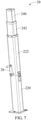
- the fixed vertical rod 22 may include a fixed vertical rod body 220 and a foldable vertical rod portion 222.
- One end of the fixed vertical rod body 220 is fixedly mounted to the base 10
- an other end of the fixed vertical rod body 220 is hinged to one end of the foldable vertical rod portion 222
- an other end of the foldable vertical rod portion 222 is mounted to the movable vertical rod 24, and the movable vertical rod 24 is movable relative to the foldable vertical rod portion 22 in a length direction of the foldable vertical rod portion 22.
- the foldable vertical rod portion 22 can pivotally rotate relative to the fixed vertical rod body 220, so that the support assembly 30 is foldable, thereby reducing a height of the calibration bracket 100 to facilitate transportation.
- the movable vertical rod 24 may include an inner rod portion 240 and an outer rod portion 242.
- the inner rod portion 240 is inserted in the outer rod portion 242, and the inner rod portion 240 is movable relative to the outer rod portion 242 in the length direction of the foldable vertical rod portion 222.
- the outer rod portion 242 is inserted in the foldable vertical rod portion 222, the outer rod portion 242 is movable relative to the foldable vertical rod portion 222 in the length direction of the foldable vertical rod portion 222, and the driving mechanism 26 is configured to drive the inner rod portion 240 to move relative to the foldable vertical rod portion 222.
- the inner rod portion 240 is inserted in the outer rod portion 242, and the outer rod portion 242 is inserted in the foldable vertical rod portion 222, so that the height of the stand assembly 20 can be reduced to nearly one-third of the original height, which improves the portability of the stand assembly 20.
- only one driving mechanism 26 can drive both the outer rod portion 242 and the inner rod portion 240 to move relative to the foldable vertical rod portion 222, and the weight of the stand assembly 20 is basically not increased.
- the outer rod portion 242 may further include a plurality of sleeve rods, one of the plurality of sleeve rods being inserted in the adjacent other.
- the foldable vertical rod portion 222 has a first sliding groove 2220 and a first snap-fit opening 2222.
- the first snap-fit opening 2222 is in communication with the first sliding groove 2220, and a cross-sectional dimension of the first snap-fit opening 2222 is less than a cross-sectional dimension of the first sliding groove 2220.
- a first stop portion 2420 is provided at an end of the outer rod portion 242, a cross-sectional dimension of the first stop portion 2420 being greater than a cross-sectional dimension of the outer rod portion 242.
- the first stop portion 2420 is inserted in the first sliding groove 2220, and the outer rod portion 242 is inserted in the first snap-fit opening 2222.
- the first stop portion 2420 abuts against a junction of the first sliding groove 2220 and the first snap-fit opening 2222, which can prevent the outer rod portion 242 from being detached from the foldable vertical rod portion 222.
- the outer rod portion 242 has a second sliding groove 2422 and a second snap-fit opening 2424.
- the second snap-fit opening 2424 is in communication with the second sliding groove 2422, and a cross-sectional dimension of the second snap-fit opening 2424 is less than a cross-sectional dimension of the second sliding groove 2422.
- the inner rod portion 240 has a second stop portion 2400, a cross-sectional dimension of the second stop portion 2400 being greater than a cross-sectional dimension of the inner rod portion 240.
- the second stop portion 2400 is inserted in the second sliding groove 2422, and the inner rod portion 240 is inserted in the second snap-fit opening 2424.
- the second stop portion 2400 abuts against a junction of the second sliding groove 2422 and the second snap-fit opening 2424, which can prevent the inner rod portion 240 from being detached from the outer rod portion 242.
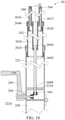
- the driving mechanism 26 includes a first threaded rotating member 260, a second threaded rotating member 262, a threaded fixed member 264, a first helical gear 266, a second helical gear 268 and a hand wheel 269.
- the first threaded rotating member 260 is mounted to the foldable vertical rod portion 222, and the first threaded rotating member 260 is rotatable relative to the foldable vertical rod portion 222 only about a central axis O, the central axis O being substantially parallel to the length direction of the foldable vertical rod portion 222.
- the second threaded rotating member 262 has a first threaded structure (not shown) and a second threaded structure (not shown) spiraling about the central axis O, a spiraling direction of the first threaded structure being the same as a spiraling direction of the second threaded structure.
- the second threaded rotating member 262 is mounted to the first threaded rotating member 260 through the first threaded structure, the second threaded rotating member 262 is mounted to the threaded fixed member 264 through the second threaded structure, and the threaded fixed member 264 is fixedly mounted to the inner rod portion 240.
- the first threaded rotating member 260 rotates relative to the foldable vertical rod portion 222, and the second threaded rotating member 262 is driven to rotate relative to one of the first threaded rotating member 260 and the threaded fixed member 264.
- the second threaded rotating member 262 is stationary relative to the first threaded rotating member 260.
- the threaded fixed member 264 moves relative to the first threaded rotating member 260 and the second threaded rotating member 262.
- first threaded rotating member 260 rotates relative to the foldable vertical rod portion 222
- second threaded rotating member 262 is stationary relative to the threaded fixed member 264.
- both the second threaded rotating member 262 and the threaded fixed member 264 move relative to the first threaded rotating member 260.
- the inner rod portion 240 is driven to move relative to the foldable vertical rod portion 222 through the first threaded rotating member 260, the second threaded rotating member 262 and the threaded fixed member 264.
- the second threaded rotating member 262 since the second threaded rotating member 262 also moves toward the foldable vertical rod portion 222, the second threaded rotating member 262 disposed in the rod member will not limit a stroke of the inner rod portion 240 and does not protrude from the inner rod portion 240, so that the stand assembly 20 is more convenient to carry.
- the first threaded rotating member, the second threaded rotating member and the threaded fixed member are all connected by using threads, after the inner rod portion 240 is moved to a designated position relative to the foldable vertical rod portion 222, the driving mechanism 26 can be self-locked.
- the first threaded rotating member 260 includes a journal portion 2600, a first screw portion 2602 and a first limiting portion 2604.
- the first journal portion 2600 is disposed at one end of the first screw portion 2602, and the first limiting portion 2604 is disposed on an other end of the first screw portion 2602.
- a cross-sectional dimension of the first journal portion 2600 is less than a cross-sectional dimension of the first screw portion 2602, and the cross-sectional dimension of the first screw portion 2602 is less than a cross-sectional dimension of the first limiting portion 2604.
- a mounting separator plate 2224 is provided in the foldable vertical rod portion 222, and the mounting separator plate 2224 is substantially horizontal.
- the journal portion 2600 is inserted in the mounting separator plate 2224. Since the first threaded rotating member 260, the second threaded rotating member 262 and the threaded fixed member 264 are connected by using threads, the first screw portion 2602 abuts against the mounting separator plate 2224, so that the first threaded rotating member 260 is rotatable relative to the foldable vertical rod portion 222 only about the central axis O.
- the mounting separator plate 2224 can limit a position of the second threaded rotating member 260.
- first threaded rotating member 260 rotates to cause the second threaded rotating member 262 to abut against the mounting separator plate 2224, the first threaded rotating member 260 continues to rotate, the second threaded rotating member 262 will remain stationary with respect to the first threaded rotating member 260, so that the threaded fixed member 264 moves toward the foldable vertical rod portion 222 until the threaded fixed member 264 also abuts against the mounting separator plate 2224. At this point, the first threaded rotating member 260 cannot continue to rotate.
- the second threaded rotating member 262 is inserted in the first threaded rotating member 260, and the first threaded structure is disposed outside the second threaded rotating member 262.
- first threaded rotating member 260 is inserted in the second threaded rotating member 262, and the first threaded structure is disposed in the second threaded structure 262.
- the second threaded rotating member 262 includes a second screw portion 2620 and a second limiting portion 2622.
- the second limiting portion 2622 is disposed at an end of the second screw portion 2620.
- a cross-sectional dimension of the second screw portion 2620 is less than a cross-sectional dimension of the second limiting portion 2622.
- the second screw portion 2620 has a first screw hole 2624 and a first accommodating groove 2626, the first screw hole 2624 being in communication with the first accommodating groove 2626.
- a cross-sectional dimension of the first screw hole 2624 is less than a cross-sectional dimension of the first accommodating groove 2626, and the first threaded structure is disposed on a hole wall of the first screw hole 2624.
- the first screw portion 2602 is inserted in the first screw hole 2624, and the limiting portion 2604 is accommodated in the first accommodating groove 2626.
- the first limiting portion 2604 is disposed at an end of the first screw portion 2602, during the rotation of the first threaded rotating member 260, when the second threaded rotating member 262 can move to a position in which the first limiting portion 2604 abuts against a junction of the first screw hole 2624 and the first accommodating groove 2626, the first threaded rotating member 260 continues to rotate, and the second threaded rotating member 262 will remain stationary with respect to the first threaded rotating member 260, so that the threaded fixed member 264 moves away from the foldable vertical rod portion 222.
- the threaded fixed member 264 is inserted in the second threaded rotating member 262, and the second threaded structure is disposed in the second threaded rotating member 262.
- the second threaded rotating member 262 is inserted in the threaded fixed member 264, and the second threaded structure is disposed outside the second threaded rotating member 262.
- the threaded fixed member 264 has a second screw hole 2640 and a second accommodating groove 2642, the second screw hole 2640 being in communication with the second accommodating groove 2642.
- a cross-sectional dimension of the second screw hole 2640 is less than a cross-sectional dimension of the second accommodating groove 2642, and the second threaded structure is disposed on a hole wall of the second screw hole 2640.
- the second screw portion 2620 is inserted in the second screw hole 2640, and the second limiting portion 2622 is accommodated in the second accommodating groove 2642.
- the second limiting portion 2622 is disposed at an end of the second screw portion 2620, during the rotation of the first threaded rotating member 260, when the second threaded rotating member 262 can move to a position in which the second limiting portion 2622 abuts against a junction of the second screw hole 2640 and the second accommodating groove 2642, the first threaded rotating member 260 continues to rotate, and the second threaded rotating member 262 remains stationary with respect to the threaded fixed member 264, so that the second threaded rotating member 262 and the threaded fixed member 264 together move away from the foldable vertical rod portion 222.
- One end of the journal portion 2600 is connected to the first screw portion 2602, and the first helical gear 266 is fixedly mounted to an other end of the journal portion 2600.
- An axis of rotation of the first helical gear 266 overlaps the central axis O, so that the first helical gear 266 and the first screw portion 260 can rotate together.
- the second helical gear 268 is mounted to the foldable vertical rod portion 222, the second helical gear 268 is rotatable relative to the foldable vertical rod portion 222 about its axis of rotation, and an axis of rotation of the second helical gear 268 is perpendicular to the central axis O.
- the hand wheel 269 is fixedly mounted to the second helical gear 268, the hand wheel 269 and the second helical gear 268 can rotate together, and the first threaded rotating member 260 can be driven to rotate through the hand wheel 269.
- the driving mechanism 26 is omitted, and the stand assembly 20 further includes a fastening mechanism 27 and an elastic body 28.
- the fastening mechanism 27 may be mounted to one end of the fixed vertical rod 22 and configured to fix the movable vertical rod 24 to the fixed vertical rod 22.
- the fastening mechanism 27 includes a fastening ring 272 and a bolt 274.
- the fastening ring 272 is sleeved on the fixed vertical rod 22.
- the fastening ring 272 may be formed by bending a metal strip.
- the bolt 274 is mounted to two ends of the fastening ring 272.
- the elastic body 28 is located in the fixed vertical rod 22 and the movable vertical rod 24.
- the elastic body 28 is compressed between the bottom of the fixed vertical rod 22 and the movable vertical rod 24.
- the elastic body 28 may be connected to the movable vertical rod 24 at a position at the bottom, the top or the middle of the movable vertical rod 24 as required.
- the elastic body 28 is a compression spring. It may be understood that, in some other embodiments, the elastic body 28 may be other elastic elements such as an elastic piece, a pneumatic rod, a hydraulic rod, or the like.
- the bolt 274 When the movable vertical rod 24 needs to be raised relative to the fixed vertical rod 22, the bolt 274 is rotated, so that the fastening ring 272 loosens the fixed vertical rod 22, and an upward force is applied on the movable vertical rod 24, so that the movable vertical rod 24 can rise in the length direction of the fixed vertical rod 22.
- an external force for example, an external force to be applied by an operator, to be applied on the movable vertical rod 24 can be reduced.
- the bolt 274 When a required position is reached, the bolt 274 is rotated to fasten the fixed vertical rod 22, so that the movable vertical rod 24 is fixed at the required position.
- the bolt 274 is rotated, so that the fastening ring 272 loosens the fixed vertical rod 22.
- the movable vertical rod 24 Under the gravity of the movable vertical rod 24 and the support assembly 30, the movable vertical rod 24 can fall in the length direction of the fixed vertical rod 22.
- a falling speed of the movable vertical rod 24 can be reduced, so that damage caused by collision on the vertical rod 24 due to an excessively large falling speed of the movable vertical rod 24 can be avoided.
- the fastening mechanism 27 may also be other structures, so long as the movable vertical rod 24 can be fixed at a required position.
- the fastening mechanism 27 may be a screw.
- the screw passes through the fixed vertical rod 22 to be in screw-thread fit with the fixed vertical rod 22.
- the screw is rotated to abut against the movable vertical rod 24, so that the movable vertical rod 24 is fixed at the required position.
- the screw is rotated to be detached from the movable vertical rod 24, so that the movable vertical rod 24 can move in the length direction of the fixed vertical rod 22 relative to the fixed vertical rod 22.
- the support assembly 30 includes a first supporting rod 31, the first beam portion 32, a second supporting rod 33, the second beam portion 34, a mounting seat 35, the connecting portion 36, an adjustment mechanism 37 and a joint mechanism 39.
- the first supporting rod 31 and the second supporting rod 33 are configured to support a target to prevent falling, especially when the target has relatively large area and weight.
- One end of the first supporting rod 31 can be pivotally connected to the first beam portion 32 through a hinge mechanism, and the like, and the first supporting rod 31 can rotate relative to the first beam portion 32 to be unfolded to be perpendicular to the first beam portion 32 and engaged with and parallel to the first beam portion 32.
- the first supporting rod 31 includes a first supporting rod body 310 and a first supporting member 312. One end of the first supporting rod body 310 is hinged to the first beam portion 32, and the first supporting member 312 is mounted at the other end of the first supporting rod body 310. A side wall of the first supporting rod body 310 is provided with a first slot (not shown).
- the second supporting rod 33 can be pivotally connected to the second beam portion 34 through a hinge mechanism, and the like, and the second supporting rod 33 can rotate relative to the second beam portion 34 to be unfolded to be perpendicular to the second beam portion 34 and engaged with and parallel to the second beam portion 34.
- the second supporting rod 33 includes a second supporting rod body 330 and a second supporting member 332.
- One end of the second supporting rod body 330 is hinged to the second beam portion 34, and the second supporting member 332 is mounted at the other end of the second supporting rod body 330.
- a side wall of the second supporting rod body 330 is provided with a second slot 3300.
- the first supporting member 312 and the second supporting member 332 extend in the same direction.
- the first slot and the second slot 3300 are arranged oppositely, and the first supporting member 312 and the second supporting member 332 can be used to jointly support a calibration element, such as a pattern plate.
- the first beam portion 32 is provided with a first fixture block 320 and a first guide rail 322.
- the first fixture block 320 and the first supporting rod 31 are both connected to the same side of the first beam portion 32.
- the first guide rail 322 is disposed on the other side of the first beam portion 32 and parallel to the first beam portion 32.
- the first guide rail 322 is configured to mount a widget for mounting the calibration element, for example, mounting a calibration target, a reflector, a laser, and the like. The widget can slide along the first guide rail 322.
- the second beam portion 34 is provided with a second fixture block 340 and a second guide rail 342.
- the second fixture block 340 and the second supporting rod 33 are both connected to the same side of the second beam portion 34.
- the second guide rail 342 is disposed on the other side of the second beam portion 34 and parallel to the second beam portion 34.
- the second guide rail 342 is configured to mount a widget for mounting the calibration element, for example, mounting a reflector, and the like. The widget can slide along the second guide rail 342.
- the first guide rail 322 and the second guide rail 342 are disposed symmetrically relative to the connecting portion 36, and the first beam portion 32 and the second beam portion 34 are also disposed symmetrically relative to the connecting portion 36.
- the first guide rail 322, the second guide rail 342, the first beam portion 32 and the second beam portion 34 are all horizontally disposed.
- the positions of the first fixture block 320 and the first slot can be interchanged, that is, the first fixture block 320 is mounted to the first supporting rod body 310, and the first slot is disposed on the first beam portion 32.
- the positions of the second fixture block 340 and the second slot 3300 may also be interchanged, that is, the second fixture block 340 is mounted to the second supporting rod body 330, and the second slot 3300 is disposed on the second beam portion 34.
- the first slot and the second slot 3300 are recessed in the corresponding beam portions.
- first guide rail 322 and the second guide rail 342 may be disposed on other surfaces, such as the top surface of the beam. In some other embodiments, the first guide rail 322 and the second guide rail 342 do not need to be disposed, and the calibration element may be directly hung on the beam by using a hook or the like.
- the first guide rail 322 and the second guide rail 342 can also have other forms, which are not necessarily shown in the figure.
- the guide rail can be one or more groove lines arranged on the top surface of the beam, and the outer wall of the beam can be used to form the groove line without mounting additional guide rails.
- a number of supporting rods is not limited by the foregoing embodiment.
- the target located at the approximately central position of the support assembly 30 can also be well supported.
- the supporting rod may also be disposed at a corresponding position for supporting.
- the supporting rod can also be disposed on a rail, and the rail is disposed on a side surface or a bottom surface of the support assembly 30, so that the supporting rod can move along the assembled support assembly 30, so as to lift, at a suitable position, the targets that may be at different positions.
- the supporting rod can also be snapped onto the support assembly 30 by using a fixture block and a slot.
- the connecting portion 36 of the beam is sleeved in the mounting base 35.
- a first surface 360 of the connecting portion 36 is recessed with positioning holes 3604.
- the connecting portion 36 is provided with a fixing groove 3620.
- a fixing surface 3624 is disposed in the fixing groove 3620.
- the fixing groove 3620 is used in conjunction with a fixing rod 354 in FIG. 18 to fix the support assembly onto the mounting base 35.
- the fixing groove 3620 is provided so that the fixing surface 3624 and the bottom surface of the mounting seat 35 are at a certain angle.
- the fixing groove 3620 may be disposed between a second surface 362 and a top surface of the beam.
- the second surface 362 is arranged parallel to the first surface 360, and there is an included angle between the fixing surface 3624 and the first surface 360 and the second surface 362.
- the fixing surface 3624 is disposed at 45 degrees with the first surface 360 and the second surface 362.
- the first beam portion 32, the second beam portion 34 and the connecting portion 36 are all square tubes, which can reduce the weight of the calibration bracket 100 and make the connecting portion 36 easy to be firmly sleeved in the adjustment mechanism 38. It may be understood that, in some other embodiments, the first beam portion 32, the second beam portion 34 and the connecting portion 36 may also be tubes of other shapes, special-shaped materials, rods, or the like, which may be polygonal or circular tubes or rods, for example. When the beam is a tube of other shapes, the fixing groove 3620 may be disposed at a position at which a specific angle can be formed between the fixing surface 3624 and the bottom surface of the mounting base 35.
- the mounting base 35 is configured to sleeve the connecting portion 36.
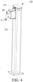
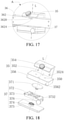
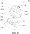
- the mounting base 35 includes a holder 352, a fixing rod 354 and a mounting casing 356.
- the mounting base 35 may be disposed on the adjustment mechanism 37, so that the mounting base 35 can rotate about an adjustment rotation axis L relative to the stand assembly 20 under adjustment of the adjustment mechanism 37, to adjust the mounting base 35 and the horizontal angle of the support assembly 30.
- the adjustment mechanism 37 is disposed above the mounting base, so as to facilitate removal and mounting of the beam from above while implementing adjustment of the horizontal angle.
- the adjustment rotation axis L is disposed in parallel to the fixed vertical rod 22 and the movable vertical rod 24, that is, when the calibration bracket 100 is placed on a horizontal plane, the adjustment rotation axis L is vertically disposed.
- the mounting base 35 is provided with a notch 350 for facilitating placement of the connecting portion 36 in the mounting base 35 or removal of the connecting portion 36 from the mounting base 35.
- the holder 352 is substantially hook-shaped to facilitate holding of the connecting portion 36.
- One end of the holder 352 is fixedly connected to the mounting casing 356, for example, mounted on an upper surface or a lateral surface of the mounting casing 356, and the other end surrounds and grasps the connecting portion 36 of a support assembly 20, leaving the notch 350.
- the holder 352 may have the shape shown in FIG. 18 , or may have other shapes, such as a circular hook shape, a hook shape of other polygons, a hook shape with a combination of a circular ring and a polygon, so long as the connecting portion 36 can be stably held.
- substantially hook-shaped herein means that the holder 352 can extend by a specific length at a specific angle, thereby supporting and holding the connecting portion 36.
- the holder 352 and the mounting casing 356 form a mounting channel through enclosure for accommodating the connecting portion 36.
- the mounting channel is in communication with the notch 350.
- Two positioning columns 3524 are provided on an inner surface of the holder 352.
- the two positioning columns 3524 are located in the mounting channel and are to be inserted into the two positioning holes 3604 (see FIG. 13 ), to facilitate positioning of the connecting portion 36 in the mounting channel.
- the function of the positioning hole is to further reduce any displacement of the support assembly 20 relative to the mounting seat 35 in the horizontal direction during calibration.
- the positioning column 3524 may also be disposed on the upper surface of the mounting casing 356 or on both the upper surface of the mounting casing 356 and the inner surface of the holder 352.
- positioning column herein includes circular, square, and elongated positioning columns
- positioning hole includes circular, square, and elongated positioning holes.
- the positioning column and the positioning holes are substantially point-shaped, there are preferably at least two positioning columns 3524 in the length direction of the connecting portion 36, to ensure that the connecting portion 36 does not move in the length direction thereof.
- the positioning column and the positioning hole are substantially elongated, only one pair of positioning column and positioning hole may be used.
- positions of the positioning hole 3604 and the positioning column 3524 may be transposed, that is, the positioning hole 3604 is provided on the holder 352 in communication with the mounting channel, and the positioning column 3524 is disposed on the first surface 360 (see FIG. 13 ).
- the fixing rod 354 is disposed on the holder 352, which includes a knob and at least one screw rod and is in screw-thread fit with the holder 352.
- a central axis of the fixing rod 354 is perpendicular to the fixing surface 3624 at the beam connecting portion 36.
- a specific angle is formed between the fixing surface 3624 and the bottom surface (that is, a horizontal plane) of the mounting base 35 and between the fixing rod 354 and the bottom surface of the mounting base 35.
- the angle is greater than 0 degrees and less than 90 degrees.
- the angle is substantially 45 degrees.
- only one fixing rod 354 needs to be used to apply, to the connecting portion 36, a pressing force toward the bottom surface and a lateral surface of the mounting base.
- the lateral surface is a side opposite to a direction in which the fixing rod 354 extends, so that the fixed base fixes the connecting portion 36 with high stability, and the support assembly can be easily disassembled and assembled.
- the mounting base 35 may have other structures, for example, a notch may not necessarily be maintained. After the connecting portion 36 is placed in the mounting base 35, a baffle or the like can be used to block the notch.
- the connecting portion 36 can also be mounted in other ways.
- the mounting base 35 may be a complete ring structure without a notch for placing the beam. In this case, the beam may be assembled first, then the mounting base 35 can be inserted, and then the fixing rod 354 is used to tighten and fix the beam.
- the bottom surface or side surface of the mounting seat 35 pressed by the connecting portion 36 may be arc-shaped or other irregular shapes.
- the fixing rod 354 may also be used to press the connecting portion 36 on these surfaces. There may be line contact between the fixing rod and these surfaces instead of surface contact, which will not affect the compression effect.
- the surface of the mounting base 35 facing away from the notch 350 may also be used to mount a calibration element, for example, a multi-line laser 200 (see FIG. 1 ).
- the mounting casing 356 is substantially a cube with an opening on one side.
- the adjustment mechanism 37 is disposed in the opening of the mounting casing 356.
- the mounting housing 356 is provided with a threaded hole 3562.
- the adjustment mechanism 37 includes a supporting shaft 371, a first elastic member 372, a rotating member 373, a bearing base 374, a pedestal 375 and an adjusting rod 376.
- the adjustment mechanism 37 is configured to adjust an angle (that is, a yaw angle) of the support assembly 20 in a horizontal direction.
- the supporting shaft 371 is received in the mounting casing 356 and fixedly mounted to the inner wall of the mounting casing 356. A central axis of the supporting shaft 371 overlaps with the adjustment rotation axis L.
- first elastic member 372 is fixed to the mounting column 3560, and the other end of the first elastic member 372 is fixed to the rotating member 373.
- the first elastic member 372 is a spring.
- the rotating member 373 is substantially a cube. One end of the rotating member is provided with a protrusion 3732. The protrusion 3732 and the first elastic member 372 are respectively located on two opposite sides of the rotating member 373. The rotating member 373 is sleeved on the bearing base 374.
- the bearing base 374 is fixedly mounted on a surface of the pedestal 375, and a central axis of the bearing base 374 overlaps with the adjustment rotation axis L.
- the rotating member 373 is fixedly mounted to the pedestal 375 and sleeved on the bearing base 374.
- One end of the supporting shaft 371 is inserted into the bearing base 374, so that the supporting shaft 371 and the mounting casing 356 can rotate together about the adjustment rotation axis L relative to the rotating member 373, the bearing base 374 and the pedestal 375.
- the pedestal 375 is mounted to the movable vertical rod 24.
- the movable vertical rod 24 can drive the pedestal 375 to rise or fall.
- the pedestal 375 is a cube.
- the pedestal 375 covers the opening of the mounting casing 356.
- the supporting shaft 371, the first elastic member 372 and the rotating member 373 are all received in a cavity formed by the mounting casing 356 and the pedestal 375.
- the adjusting rod 376 is mounted in the threaded hole 3562. By rotating the adjusting rod 376, the adjusting rod 376 abuts against the protrusion 3732, and pushes the mounting base 35 to rotate about the adjustment rotation axis L relative to the rotating member 373 and the pedestal 375, thereby adjusting the mounting base 35 and the horizontal angle of the connecting portion 36, so that the first elastic member 372 is stretched.
- the adjusting rod 376 is rotated in an opposite direction, and the mounting base 35, rotates, through pulling of the first elastic member 372, about the adjustment rotation axis L relative to the rotating member 373 and the pedestal 375 to return to its original position.
- the pedestal 375 may be omitted, and the rotating member 373 and the bearing base 374 may be fixedly mounted on the top surface of the movable vertical rod 24 directly.
- the foregoing adjustment mechanism 37 may be selectively used.
- the mounting casing 356 of the mounting base 35 may be cancelled, and the holder 352 is mounted on the top surface of the movable vertical rod 24 or other additional mounting surfaces.
- the holder 352 may also extend to form a bottom surface and surround the lower surface of the connecting portion 36 of the support assembly 30, that is, the holder 352 may have a bottom surface mounted to the mounting casing 356.
- joint mechanisms 39 there are two joint mechanisms 39.
- One of the joint mechanisms 39 is connected between the first beam portion 32 and the connecting portion 36, and the other of the joint mechanisms 39 is connected between the second beam portion 34 and the connecting portion 36.
- the joint mechanism 39 is fixed in the wall tubes of the first beam portion 32, the second beam portion 34 and the connecting portion 36.
- the joint mechanism 39 is fixed outside the wall tubes of the first beam portion 32, the second beam portion 34 and the connecting portion 36, and is connected to cross-sections of the wall tubes of the first beam portion 32, the second beam portion 34 and the connecting portion 36 by snapping, screwing, bonding, and the like.
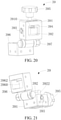
- FIG. 20, FIG. 21 and FIG. 22 together show a first implementation of a structure of a joint mechanism 39.
- the joint mechanism 39 includes a first fixing member 391, a second fixing member 396, a first rotating shaft 397, a fastening member 392, a second rotating shaft 393, a second elastic member 394 and a screwing mechanism 395.
- the first fixing member 391 and the second fixing member 396 are hinged to each other through the first rotating shaft 397.
- the first fixing member 391 is substantially a cube.
- One end of the first fixing member is hinged to one end of the second fixing member 396.
- the first fixing member 391 is provided with a first through hole 3910.
- the fastener 392 is received in the first through hole 3910, the second rotating shaft 393 passes through the middle of the fastener 392, and two ends of the second rotating shaft 393 are respectively mounted to side walls of the first fixing member 391.
- the fastener 392 can rotate about the second rotating shaft 393.
- a hook portion 3922 extends from one end of the fastener 392.
- One end of the second elastic member 394 abuts against the other end of the fastener 392, and the other end of the second elastic member 394 abuts against an inner wall of the first fixing member 391.
- the second elastic member 394 is a compression spring for restoration from elastic deformation, so as to push the fastener 392 to rotate about the second rotating shaft 393.
- the screwing mechanism 395 includes a knob and at least one section of screw rod. One end of the screwing mechanism 395 passes through the first fixing member 391 from the outside of the first fixing member 391, and abuts against the fastening member 392.
- the screwing mechanism 395 and the second elastic member 394 are located on the same side of the central axis of the second rotating shaft 393, and the hook portion 3922 is located on the other side of the central axis of the second rotating shaft 393.
- the second fixing member 396 is also substantially a cube and provided with a second through hole 3960.
- An inner wall of the second through hole 3960 is provided with a bulge 3962.
- the first fixing member 391 is fixed to the inside of the connecting portion 36, and the second fixing member 396 is fixed to the inside of the first beam portion 32 or the second beam portion 34, so that the first beam portion 32 or the second beam portion 34 can be engaged with the connecting portion 36.
- the first fixing member 391 and the second fixing member 396 are fastened, the first fixing member 391 is in contact with the second fixing member 396, and the first through hole 3910 is in communication with the second through hole 3960.
- the hook portion 3922 is fastened to the locking protrusion 3962, and the screwing mechanism 395 is rotated, so that the screwing mechanism 395 presses the fastening member 392, and the hook portion 3922 is further fastened to the locking protrusion 3962, so that the first beam portion 32 or the second beam portion 34 is stably unfolded relative to the connecting portion 36.
- the screwing mechanism 395 is rotated to be disengaged from the fastening member 392, so that the first fixing member 391 rotates relative to the second fixing member 396, and the hook portion 3922 is separated from the locking protrusion 3962.
- the first fixing member 391 is separated from the second fixing member 396, so that the first beam portion 32 or the second beam portion 34 can rotate relative to the connecting portion 36, and the support assembly 30 is folded.
- the hook portion 3922 can be easily fastened to the locking protrusion 3962, so that the hook portion 3922 and the locking protrusion 3962 are fastened to each other in advance, and then the screwing mechanism 395 presses the fastening member 392, so that the hook portion 3922 is further fastened to the locking protrusion 3962.
- positions of the first fixing member 391 and the second fixing member 396 can be interchanged, that is, the first fixing member 391 is fixed to the inside of the first beam portion 32 or the second beam portion 34, and the second fixing member 396 is fixed to inside of the connecting portion 36.
- first fixing member 391 and the second fixing member 396 may also be integrally formed with inner walls of the first beam portion 32, the second beam portion 34 or the connecting portion 36, that is, the first fixing member 391 and the second fixing member 396 may be a part of the inner walls of the first beam portion 32, the second beam portion 34 or the connecting portion 36.
- the first fixing member 391 and the second fixing member 396 may not be connected by using a first rotating shaft or are not connected.
- first beam portion 32 or the second beam portion 34 and the outer wall of the connecting portion 36 are connected by using an additional rotating shaft, which can also implement the pivotable connection between the first beam portion 32 or the second beam portion 34 and the connecting portion 36.
- the joint mechanism 39a provided in the second implementation is substantially the same as the joint mechanism 39 in the foregoing embodiment.
- a difference is that one end of the fastener 392a is provided with a hook portion 3922a and a bump 3924a.
- Two hook portions 3922a are located on two opposite sides of the bump 3924a.
- An inner wall of the second through hole 3960 is provided with a bulge 3962a.
- a position of each of the bulges 3962a corresponds to a position of a corresponding one of the hook portions 3922a.
- the knob 395 is replaced with a button 395a.
- the button 395a is mounted to the second fixing member 396.
- the second elastic member 394 is a compression spring compressed between the first fixing member 391 and the fastener 392a.
- first fixing member 391 and the second fixing member 396 When the first fixing member 391 and the second fixing member 396 are closed, the first fixing member 391 is in contact with the second fixing member 396, and the first through hole 3910 is in communication with the second through hole 3960.
- the second elastic member 394 abuts against the fastener 392a, so that the two hook portions 3922a are respectively fastened to the two bulges 3962a.
- the first fixing member 391 and the second fixing member 396 are fastened to each other, so that the first beam portion 32 or the second beam portion 34 is unfolded relative to the connecting portion 36.
- the button 395a When the button 395a is pressed, and the button 395a pushes the bump 3924a to push the fastening member 392a to rotate around the second rotating shaft 393, the hook portion 3922a is separated from the locking protrusion 3962a, and the second elastic member 394 is further compressed.
- the first fixing member 391 can rotate relative to the second fixing member 396, so that the first fixing member 391 is separated from the second fixing member 396, and the first beam portion 32 or the second beam portion 34 can rotate relative to the connecting portion 36, to fold the support assembly 30.
- the button 395a is loosened to make the button 395a far away from the fastening member 392a, and the second elastic member 394 recovers elastic deformation to push the fastening member 392a to rotate around the second rotating shaft 393, so that the hook portion 3922a is fastened to the locking protrusion 3962a.
- the calibration bracket 100 may further include a fastening structure 50.
- One fastening structure 50 is connected between the first beam portion 32 and the connecting portion 36, and the other fastening structure 50 is connected between the second beam portion 34 and the connecting portion 36.
- Each of the buckle structures 50 includes a first buckle 52 and a second buckle 54.
- the connecting portion 36 is provided with a first fastener 52, one end of the first fastener 52 is hinged to the connecting portion 36, and one end of the first fastener 52 hinged to the connecting portion 36 is provided with a pulling portion 522.
- the other end of the first fastener 52 is provided with a hook rod 524, and the first beam portion 32 or the second beam portion 34 is provided with a second fastener 54.
- the second fastener 54 is provided with a fastening portion 544.
- a hinge joint of the first beam portion 32 or the second beam portion 34 and the connecting portion 36 is located on one side of the connecting portion 36, and the first fastener 52 and the second fastener 54 are located on the other side of the connecting portion 36.
- the first beam portion 32 and the second beam portion 34 are unfolded relative to the connecting portion 36, the first beam portion 32 and the second beam portion 34 are respectively in contact with the connecting portion 36, and the hook rod 524 is fastened to the fastening portion 544.
- the hook rod 524 is separated from the fastening portion 544, and the first fastener 52 and the second fastener 54 may be separated, so that the first beam portion 32 or the second beam portion 34 can be folded relative to the connecting portion 36.
- positions of the first fastener 52 and the second fastener 54 can be interchanged, that is, the first fastener 52 is disposed on the first beam portion 32 or the second beam portion 34, and the second fastener 54 is disposed on the connecting portion 36.
- the first fastener 52 and the second fastener 54 can be used in conjunction with the joint mechanism 39. That is, in this case, the joint mechanism 39 is disposed in inner walls of the first beam portion 32, the second beam portion 34 and the connecting portion 36.
- the first fastener 52 and the second fastener 54 can be used alone. That is, in this case, the joint mechanism 39 is not disposed in inner walls of the first beam portion 32, the second beam portion 34 and the connecting portion 36.
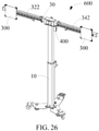
- another embodiment of the present invention also provides a calibration system 600, including a calibration element and the calibration bracket 100 provided in the foregoing embodiments.
- the calibration element can be mounted to the calibration bracket 100.
- the calibration element is a reflector 300 and a distance measurement apparatus 400 (see FIG. 23 ).
- the reflector 300 may be mounted on a first guide rail 322 or a second guide rail 342 via a slider.
- the slider is mounted to the first guide rail 322 or the second guide rail 342, and can slide along the first guide rail 322 or the second guide rail 342 together with the reflector 300, and the distance measurement apparatus 400 is fixedly mounted to the support assembly 30.
- the reflector 300 may also be a target 300, and two targets are mounted on the first guide rail 322 and the second guide rail 342 through the slider.
- the reflector or the target 300 may be further directly mounted to the support assembly 30 by using a hook, or the like. In this case, the first guide rail 322 and the second guide rail 342 may be cancelled.
- the foregoing distance measurement apparatus 400 is configured to measure a height of the support assembly 30 from the ground, which is preferably displayed on a liquid crystal display screen of the distance measurement apparatus 400.
- the distance measurement apparatus 400 is a laser rangefinder.
- a through hole 120 is disposed on the base 10 so that a laser of the laser rangefinder 400 aims at the ground to measure the height of the support assembly 30 from the ground.
- the calibration element is a pattern plate 500 (see FIG. 27 ).
- the first supporting member 312 and the second supporting member 332 jointly support the pattern plate 500 to prevent falling.
- a first fixing block 510 may be further mounted to the first guide rail 322.
- the first fixing block 510 can slide in the first guide rail 322.
- a second fixing block 520 is mounted to the second guide rail 342.
- the second fixing block 520 can slide in the second guide rail 342.
- the first fixing block 510 and the second fixing block 520 are respectively located on two opposite sides of the pattern plate 500.
- the first fixing block 510 and the second fixing block 520 collaboratively clamp the pattern plate 500.
- the first fixing block 510 and the second fixing block 520 are sliders for mounting the reflector 300.
- a slot for clamping the pattern plate 500 is provided on opposite sides of the slider, to form a fixing block.
- the first fixing block 510 and the second fixing block 520 may also be magnetic blocks, which attract the pattern plate 500 from the back through magnetic absorption, to cause the pattern plate 500 to be more firmly mounted to the support assembly 30.
Landscapes
- Engineering & Computer Science (AREA)
- General Engineering & Computer Science (AREA)
- Mechanical Engineering (AREA)
- Physics & Mathematics (AREA)
- General Physics & Mathematics (AREA)
- Computer Networks & Wireless Communication (AREA)
- Radar, Positioning & Navigation (AREA)
- Remote Sensing (AREA)
- Motorcycle And Bicycle Frame (AREA)
- Pivots And Pivotal Connections (AREA)
- Body Structure For Vehicles (AREA)
- Details Of Measuring And Other Instruments (AREA)
Abstract
Description
- The present application claims priority to
Chinese Patent Application No. 201910214915.5, entitled "CALIBRATION SYSTEM AND CALIBRATION BRACKET THEREOF" filed with National Intellectual Property Administration, PRC on March 20, 2019 - The present application relates to the technical field of vehicle maintenance and device calibration, and in particular, to a calibration system and a calibration bracket thereof.
- An advanced driver assistant system (ADAS for short) is an active security technology of collecting environmental data inside and outside a vehicle at the prime time by using various sensors mounted to the vehicle to perform technical processing such as identification, detection, and tracking of static and dynamic objects, enabling a driver to perceive a potential danger as quickly as possible, thereby attracting attention and improving security. Sensors adopted in the ADAS mainly include a camera, a radar, a laser, and an ultrasonic wave, which can detect light, heat, pressure, or other variables for monitoring status of a vehicle, and are generally located on front and rear bumpers, on a side mirror, inside a steering column, or on a windscreen of the vehicle. During use of the vehicle, vibration, collision, environmental temperature and humidity, and the like change physical mounting states of the foregoing sensors, and therefore irregular correction or calibration is required.
- During correction or calibration of the foregoing sensors, calibration elements are usually hung on the calibration bracket to correct or calibrate the sensors on the vehicle. However, most of current calibration brackets have relatively large volumes and are complicated to assemble and difficult to move.
- Embodiments of the present invention are intended to provide a calibration system and a calibration bracket thereof, which can resolve the technical problem in the prior art that a calibration bracket has relatively large volumes and is difficult to move.
- The embodiments of the present invention adopt the following technical solution to resolve the technical problem.
- According to one aspect, a calibration bracket is provided, including a base, a stand assembly and a support assembly, the support assembly being configured to mount a calibration element, the stand assembly including: a fixed vertical rod, one end of the fixed vertical rod being mounted to the base; a movable vertical rod mounted to an other end of the fixed vertical rod, the movable vertical rod being movable relative to the fixed vertical rod only along a central axis, and the support assembly being mounted to the movable vertical rod; a driving mechanism, including a first threaded rotating member, a second threaded rotating member and a threaded fixed member, the first threaded rotating member being mounted to the fixed vertical rod and being rotatable relative to the fixed vertical rod only about the central axis, the second threaded rotating member having a first threaded structure and a second threaded structure spiraling about the central axis, a spiraling direction of the first threaded structure being the same as a spiraling direction of the second threaded structure, the second threaded rotating member being mounted to the first threaded rotating member through the first threaded structure and being mounted to the threaded fixed member through the second threaded structure, and the threaded fixed member being fixedly mounted to the movable vertical rod.
- In some embodiments, the first threaded rotating member is inserted in the second threaded rotating member, and the first threaded structure is disposed in the second threaded rotating member.
- In some embodiments, the first threaded rotating member includes a first screw portion and a first limiting portion, the first limiting portion being disposed at an end of the first screw portion. The second threaded rotating member has a first screw hole and a first accommodating groove, the first screw hole being in communication with the first accommodating groove. The first threaded structure is disposed on a hole wall of the first screw hole. The first screw portion is inserted in the first screw hole, and the first limiting portion is accommodated in the first accommodating groove. A cross-sectional dimension of the first limiting portion is greater than a cross-sectional dimension of the first screw portion.
- In some embodiments, the second threaded rotating member is inserted in the first threaded rotating member, and the first threaded structure is disposed outside the second threaded rotating member.
- In some embodiments, the second threaded rotating member is inserted in the threaded fixed member, and the second threaded structure is disposed outside the second threaded rotating member.
- In some embodiments, the second threaded rotating member includes a second screw portion and a second limiting portion, the second limiting portion being disposed at an end of the second screw portion. The threaded fixed member has a second screw hole and a second accommodating groove, the second screw hole being in communication with the second accommodating groove. The second threaded structure is disposed on a hole wall of the second screw hole. The second screw portion is inserted in the second screw hole, and the second limiting portion is accommodated in the second accommodating groove. A cross-sectional dimension of the second limiting portion is greater than a cross-sectional dimension of the second screw portion.
- In some embodiments, the threaded fixed member is disposed in the second threaded rotating member, and the second threaded structure is disposed in the second threaded rotating member.
- In some embodiments, the driving mechanism further includes a hand wheel configured to drive the first threaded rotating member to rotate.
- In some embodiments, the driving mechanism further includes a first helical gear and a second helical gear, the first helical gear being fixedly mounted to the first threaded rotating member, and an axis of rotation of the first helical gear overlapping the central axis. The second helical gear is mounted to the fixed vertical rod, the second helical gear is rotatable relative to the fixed vertical rod about its axis of rotation, and an axis of rotation of the second helical gear is perpendicular to the central axis. The first helical gear is meshed with the second helical gear.
- In some embodiments, the fixed vertical rod has a mounting separator plate. The first threaded rotating member includes the first screw portion and a journal portion, the journal portion being disposed at the end of the first screw portion. The journal portion is inserted in the mounting separator plate, and the cross-sectional dimension of the first screw portion is greater than a cross-sectional dimension of the journal portion, so that the first threaded rotating member is rotatable relative to the fixed vertical rod only about the central axis.
- In some embodiments, the movable vertical rod is inserted in the fixed vertical rod, so that the movable vertical rod is movable relative to the fixed vertical rod along the central axis.
- In some embodiments, cross-sections of both the movable vertical rod and the fixed vertical rod are non-circular.
- In some embodiments, the movable vertical rod includes an inner rod portion and an outer rod portion, the inner rod portion being inserted in the outer rod portion, the outer rod portion being inserted in the fixed vertical rod, and the threaded fixed member being fixedly mounted to the inner rod portion.
- In some embodiments, the outer rod portion has a second sliding groove and a second snap-fit opening, the second sliding groove being in communication with the second snap-fit opening. The inner rod portion has a second stop portion, a cross-sectional dimension of the inner rod portion being less than a cross-sectional dimension of the second stop portion. The second stop portion is inserted in the second sliding groove, and the inner rod portion is inserted in the second snap-fit opening.
- In some embodiments, the fixed vertical rod includes a fixed vertical rod body and a foldable vertical rod portion. One end of the fixed vertical rod body is mounted to the base, an other end of the fixed vertical rod body is mounted to the foldable vertical rod portion, and the foldable vertical rod portion is pivotably rotatable relative to the fixed vertical rod body. The movable vertical rod is mounted to the foldable vertical rod portion and is movable relative to the foldable vertical rod portion along the central axis. The first threaded rotating member is mounted to the foldable vertical rod portion and is rotatable relative to the foldable vertical rod portion only about the central axis.
- In some embodiments, the fixed vertical rod has a first sliding groove and a first snap-fit opening. The first sliding groove is in communication with the first snap-fit opening. The movable vertical rod has a first stop portion, a cross-sectional dimension of the movable vertical rod being less than a cross-sectional dimension of the first stop portion. The first stop portion is inserted in the first sliding groove, and the movable vertical rod is inserted in the first snap-fit opening.
- In some embodiments, the support assembly is mounted to a top of the movable vertical rod.
- According to another aspect, a calibration system is provided, including a calibration element and the foregoing calibration bracket, where the calibration element may be hung on the calibration bracket.
- Compared with the prior art, in the calibration bracket of this embodiment, the first threaded rotating member rotates relative to the fixed vertical rod, which can drive the second threaded rotating member, the threaded fixed member, and the movable vertical rod to move in the direction of the fixed vertical rod together, so that the volume of the calibration bracket is reduced, facilitating removal of the calibration bracket.
- One or more embodiments are exemplarily described with reference to the corresponding figures in the accompanying drawings, and the descriptions are not to be construed as limiting the embodiments. Elements in the accompanying drawings that have same reference numerals are represented as similar elements, and unless otherwise particularly stated, the figures in the accompanying drawings are not drawn to scale.
-
FIG. 1 is a three-dimensional view of a calibration bracket according to an embodiment of the present invention, where a multi-line laser is hung on the calibration bracket. -
FIG. 2 is a three-dimensional view of the calibration bracket shown inFIG. 1 from another perspective. -
FIG. 3 is a three-dimensional view of the calibration bracket shown inFIG. 1 , where a support assembly of the calibration bracket is in a folded state. -
FIG. 4 is a three-dimensional view of a stand assembly of the calibration bracket shown inFIG. 1 . -
FIG. 5 is a three-dimensional view of a stand assembly according to still other embodiments. -
FIG. 6 is a three-dimensional view of the stand assembly shown inFIG. 5 after being folded. -
FIG. 7 is a three-dimensional view of the stand assembly shown inFIG. 5 after being extended. -
FIG. 8 is a partial cross-sectional view of the stand assembly shown inFIG. 5 . -
FIG. 9 is a partial cross-sectional view of the stand assembly shown inFIG. 7 . -
FIG. 10 is a partial cross-sectional view of the stand assembly shown inFIG. 7 from another perspective. -
FIG. 11 is a partial cross-sectional view of the stand assembly shown inFIG. 5 from another perspective. -
FIG. 12 is a three-dimensional view of a stand assembly according to still other embodiments. -
FIG. 13 is an exploded view of the stand assembly shown inFIG. 12 . -
FIG. 14 is a three-dimensional view of a support assembly of the calibration bracket shown inFIG. 1 . -
FIG. 15 is a cross-sectional view of the support assembly shown inFIG. 14 . -
FIG. 16 is an exploded view of the support assembly shown inFIG. 14 ; -
FIG. 17 is a partial enlarged view of a part A inFIG. 14 . -
FIG. 18 is an exploded view of an adjustment mechanism of the support assembly shown inFIG. 14 . -
FIG. 19 is an exploded view of the adjustment mechanism shown inFIG. 18 from another perspective. -
FIG. 20 is a three-dimensional view of a joint mechanism of the support assembly shown inFIG. 14 . -
FIG. 21 is a three-dimensional view of the joint mechanism shown inFIG. 20 from another perspective. -
FIG. 22 is a cross-sectional view of the joint mechanism shown inFIG. 20 . -
FIG. 23 is a three-dimensional view of a joint mechanism according to some embodiments. -
FIG. 24 is a cross-sectional view of the joint mechanism shown inFIG. 23 . -
FIG. 25 is a three-dimensional view of a first buckle and a second buckle buckled with each other according to some embodiments. -
FIG. 26 is a three-dimensional view of a calibration system according to another embodiment, where the calibration system includes a calibration bracket and a calibration element, the calibration element being a reflector hung on the calibration bracket. -
FIG. 27 is a three-dimensional view of a calibration system shown inFIG. 26 , where the reflector is replaced with a pattern plate mounted to the calibration bracket. - For ease of understanding the present invention, the present invention is described in more detail below with reference to the accompanying drawings and specific embodiments. It should be noted that, when a component is expressed as "being fixed to" another component, the component may be directly on the another component, or one or more intermediate components may exist between the component and the another component. When one component is expressed as "being connected to" another component, the component may be directly connected to the another component, or one or more intermediate components may exist between the component and the another component. In the description of this specification, orientation or position relationships indicated by terms such as "up", "down", "inside", "outside", "vertical", and "horizontal" are based on orientation or position relationships shown in the accompanying drawings, and are merely used for ease of description of the present invention and for brevity of description, rather than indicating or implying that the mentioned apparatus or element needs to have a particular orientation or needs to be constructed and operated in a particular orientation, and therefore should not be understood as a limitation on the present invention. In addition, terms "first" and "second" are merely used for description and should not be understood as indicating or implying relative importance.
- Unless otherwise defined, meanings of all technical and scientific terms used in the specification are the same as those usually understood by a person skilled in art of the present invention. Terms used in the specification of the present invention are merely intended to describe objectives of the specific embodiment, and are not intended to limit the present invention. A term "and/or" used in this specification includes any or all combinations of one or more related listed items.
- In addition, technical features involved in different embodiments of the present invention described below may be combined together if there is no conflict.
- Referring to
FIG. 1 ,FIG. 2 andFIG. 3 together, acalibration bracket 100 provided in an embodiment of the present invention includes abase 10, astand assembly 20 and asupport assembly 30. Thestand assembly 20 is fixedly connected to thebase 10. Thesupport assembly 30 includes afirst beam portion 32, asecond beam portion 34 and a connectingportion 36. The connectingportion 36 is mounted to thestand assembly 20. One end of the connectingportion 36 is hinged to thefirst beam portion 32, and the other end of the connectingportion 36 is hinged to thesecond beam portion 34. Thefirst beam portion 32 and thesecond beam portion 34 can respectively rotate toward each other relative to the connectingportion 36, to fold thesupport assembly 30. Thefirst beam portion 32 and thesecond beam portion 34 can also respectively rotate away from each other relative to the connectingportion 36, to unfold thesupport assembly 30. - The "mounting" includes fixed mounting such as welding mounting as well as detachable mounting.
- The
support assembly 30 may be configured to hang a calibration element, for example, amulti-line laser 200, a calibration target, a radar reflection or absorption apparatus, and the like, to calibrate a vehicle-mounted driver assistant system. - In the
calibration bracket 100 of this embodiment, thefirst beam portion 32 and thesecond beam portion 34 can pivotally rotate relative to the connectingportion 36, respectively, to fold thesupport assembly 30, so that a volume of thecalibration bracket 100 can be reduced to facilitate shipment. - The
first beam portion 32, thesecond beam portion 34 and the connectingportion 36 constitute a beam. - Optionally, the support assembly is mounted on the top surface of a movable vertical rod. In this way, a center of gravity of the support assembly is closer to a center of gravity of the vertical rod compared with a traditional calibration bracket, so that stability of the calibration bracket can be improved and a base with a smaller area can be used.
- Optionally, the
first beam portion 32 and thesecond beam portion 34 can rotate toward each other relative to the connectingportion 36, for example, which can be folded together downward, upward, forward, and backward. Optionally, when thefirst beam portion 32 and thesecond beam portion 34 are folded downward, a length of the connectingportion 36 can be relatively short, and thefirst beam portion 32 and thesecond beam portion 34 are in a drooping state. In this way, thesupport assembly 30 does not need to be removed from thestand assembly 20, and space occupied by thecalibration bracket 100 will be significantly reduced, which can be carried conveniently in vehicles. When thefirst beam portion 32 and thesecond beam portion 34 are folded upward, forward and backward, a device for rotating the beam may be disposed, so that thefirst beam portion 32 and thesecond beam portion 34 are finally folded downward, or may be in a drooping state. Alternatively, the length of the connectingportion 36 can be made relatively long, so that thefirst beam portion 32 and thesecond beam portion 34 can be placed close to the connectingportion 36 after being folded and can be fixed to the connectingportion 36 by using a releasable fixing device. In the latter case, in order to further reduce the space occupied by thecalibration bracket 100, thesupport assembly 30 may be removed from thestand assembly 20 and then mounted to thestand assembly 20 after being carried to a required place. - A person skilled in the art may understand that the manner of folding the
support assembly 30 is not limited to the foregoing manners. For example, the beam may be folded into two ends, and there is no connectingportion 36 at this time. The beam may also be folded into four or more sections. However, three sections are preferred, because in this case a middle section of the beam has no fracture. In this way, the beam can be stably fixed onto the vertical rod by using only one fastening component at the middle section. - The
base 10 includes abase body 12, aroller 14, aheight adjustment member 16 and apull ring 18. - The
base body 12 has a triangular claw shape and includes three claws extending in three different directions. Thebase body 12 may be made of a metal material. - The
roller 14 is mounted to a bottom surface of thebase body 12, and there may be threerollers 14. Each of therollers 14 is mounted to an end of a corresponding one of the claws to facilitate movement of thebase body 12. In this embodiment, theroller 14 is an omni-directional moving roller, so that thebase body 12 can move toward any direction. - The
height adjustment member 16 is mounted to thebase body 12 for adjusting a height of thebase body 12. In this embodiment, theheight adjustment member 16 is an adjustment knob, and there are three height adjustment members. There is at least one section of screw rod under the knob, and the screw rod is mated with threads of a through hole at the base to implement height adjustment. Each of theheight adjustment members 16 is mounted to a corresponding one of the claws and is close to a corresponding one of therollers 14, and the threeheight adjustment members 16 are distributed in a regular triangle. - The
pull ring 18 can be mounted to an upper surface of one of the claws to facilitate pulling of thecalibration bracket 100. - It may be understood that, in some other embodiments, a shape of the
base body 12 may vary according to an actual requirement, and is not limited to a triangle claw shape. For example, thebase body 12 may be a rectangle or a circle. The number ofrollers 14 andheight adjustment members 16 can be increased or decreased according to actual needs. For example, the triangular-claw-shapedbase body 12 may be provided with two height adjustment members and mated with a foot with a fixed height, to adjust the angle of thebase body 12. - Referring to
FIG. 4 andFIG. 5 together, thestand assembly 20 may include a fixedvertical rod 22, a movablevertical rod 24 and adriving mechanism 26. The movablevertical rod 24 is sleeved in the fixedvertical rod 22, and can move along a length direction of the fixedvertical rod 22 relative to the fixedvertical rod 22. Thedriving mechanism 26 is mounted to the fixedvertical rod 22 for driving the movablevertical rod 24 to move along the length direction of the fixedvertical rod 22 relative to the fixedvertical rod 22. By connecting the movablevertical rod 24 and the fixedvertical rod 22 in a sleeving manner, a height of thestand assembly 20 can be reduced to nearly half of an original height. In addition, thecross bar assembly 30 is folded, so that thestand assembly 20 can be very suitable to be carried in a trunk of a transportation means such as a vehicle. - It may be understood that the fixed vertical rod may also be used as an inner rod and the movable vertical rod as an outer rod as required. The
driving mechanism 26 is mounted to the fixedvertical rod 22 and configured to drive the movablevertical rod 24 to move in the length direction of the fixedvertical rod 22 relative to the fixedvertical rod 22. - Optionally, the fixed
vertical rod 22 and the movablevertical rod 24 are square tubes. The movablevertical rod 24 is closely sleeved in the fixedvertical rod 22, so that the movablevertical rod 24 can move only in the length direction of the fixedvertical rod 22 relative to the fixedvertical rod 22, and the movablevertical rod 24 can be prevented from moving in other directions relative to the fixedvertical rod 22. This configuration is very important for thecalibration bracket 100 to be foldable, because during the calibration, a fixed relative position relationship between components of thecalibration bracket 100 is required. For example, a laser may need to be fixed on an outer surface of the fixedvertical rod 22, and a center axis of the vehicle is positioned by using the laser, thereby determining a relative position between a target carried on thesupport assembly 30 and the vehicle. Therefore, even a slight change in relative positions between the components affects calibration accuracy or requires an additional tuning mechanism for compensation. If the relative positions between the components change greatly, the additional tuning mechanism may fail. Therefore, in the sleeving mode, relative movement, such as relative rotation between the movablevertical rod 24 and the fixedvertical rod 22 other than relative movement in the length direction needs to be eliminated. A simple method is that both the movablevertical rod 24 and the fixedvertical rod 22 are square tubes, which can ensure that only relative movement in the length direction occurs therebetween. - It may be understood that, in some other embodiments, the fixed
vertical rod 22 and the movablevertical rod 24 may also be tubes of other shapes, for example, tubes with mutually matched polygonal cross-sections, so that the movablevertical rod 24 can move along the length direction of the fixedvertical rod 22 relative to the fixedvertical rod 22, and the movablevertical rod 24 can be prevented from moving toward other directions relative to the fixedvertical rod 22. The expression "matching each other" herein does not necessarily require that the cross-sections of the fixedvertical rod 22 and the movablevertical rod 24 need to be the same. For example, the cross-section of the fixedvertical rod 22 disposed outside may be hexagonal, and the cross-section of the movablevertical rod 24 disposed inside may be a quadrilateral connected to the hexagon, which can also cause the movablevertical rod 24 to only move only in the length direction of the fixedvertical rod 22 relative to the fixedvertical rod 22. The cross-sections of the fixedvertical rod 22 and the movablevertical rod 24 may also be elliptical cylindrical tubes matching each other. The elliptical cross-section can also restrict the relative rotation between the fixed vertical rod and the movable vertical rod to a specific extent. - The fixed
vertical rod 22 and the movablevertical rod 24 may also be cylindrical tubes with a circular cross-section. In this case, the fixedvertical rod 22 can be prevented, by using a guide mechanism, from rotating relative to the movablevertical rod 24. The guide mechanism is configured to guide the movablevertical rod 24 to move stably relative to the fixedvertical rod 22. Alternatively, a mechanism for detecting and adjusting the movement of the fixedvertical rod 22 relative to the movablevertical rod 24 in other directions other than the length direction is additionally disposed on other components of thecalibration bracket 100. A simple guide mechanism is a guide rail and a slider apparatus matching the guide rail. The guide mechanism may be provided on a surface at which the fixedvertical rod 22 is in contact with the movablevertical rod 24. A guide rail is disposed on one of the fixed vertical rod and the movable vertical rod, and a slider apparatus such as a bump, a plastic rubber strip, a roller, a ball, a gear, and the like is disposed on the other. In this case, the slider apparatus is restricted to move on the guide rail, and it can also be ensured that only the relative movement in the length direction occurs between the two vertical rods. The guide rail may be a groove, a linear protrusion, a rack, and the like additionally disposed on the tube wall of the vertical rod, or may be a groove, a linear protrusion, a groove formed between two linear protrusions, and the like formed by the tube wall of the vertical rod. In other words, the vertical rod uses a special-shaped tube wall, and the tube wall has a part that can be used as the guide rail, such as a groove, a linear protrusion, and the like. Similarly, the slider apparatus may be an additional component that is additionally disposed on the tube wall of the vertical rod, or may be a protruding structure formed by the tube wall of the vertical rod without a need to dispose additional components on the tube wall of the vertical rod. In addition, a mechanism that achieves transmission through meshing such as a rack also has a guiding effect, which is also classified into a guide rail category in this specification. Transmission mechanisms such as a gear and a rack described in the following embodiments can also achieve a guiding effect. Optionally, the rack may be disposed in the groove guide rail. - It may be understood that positions for disposing the guide rail and the slider apparatus may be transposed. The guide rail may be disposed on the movable vertical rod, and the slider apparatus may be disposed on the fixed vertical rod, or the positions for disposing the guide rail and the slider apparatus may be transposed.
- It may be understood that the guide mechanism is not limited to being used for the fixed
vertical rod 22 and the movablevertical rod 24 with a circular cross-section. The fixedvertical rod 22 and the movablevertical rod 24 with other cross-sectional shapes may also use the guide mechanism to enhance a guiding effect and obtain more stable or less frictional relative movement. For non-circular cross-sectional shapes, the guide rail may also not be used, but only a linear motion apparatus is used to obtain more stable or less frictional relative movement. In this case, the non-circular external vertical rod plays a guiding role. - Referring to
FIG. 5 to FIG. 7 together, the fixedvertical rod 22 may include a fixedvertical rod body 220 and a foldablevertical rod portion 222. One end of the fixedvertical rod body 220 is fixedly mounted to thebase 10, an other end of the fixedvertical rod body 220 is hinged to one end of the foldablevertical rod portion 222, an other end of the foldablevertical rod portion 222 is mounted to the movablevertical rod 24, and the movablevertical rod 24 is movable relative to the foldablevertical rod portion 22 in a length direction of the foldablevertical rod portion 22. - In the
calibration bracket 100 of this embodiment, the foldablevertical rod portion 22 can pivotally rotate relative to the fixedvertical rod body 220, so that thesupport assembly 30 is foldable, thereby reducing a height of thecalibration bracket 100 to facilitate transportation. - The movable
vertical rod 24 may include aninner rod portion 240 and anouter rod portion 242. Theinner rod portion 240 is inserted in theouter rod portion 242, and theinner rod portion 240 is movable relative to theouter rod portion 242 in the length direction of the foldablevertical rod portion 222. Theouter rod portion 242 is inserted in the foldablevertical rod portion 222, theouter rod portion 242 is movable relative to the foldablevertical rod portion 222 in the length direction of the foldablevertical rod portion 222, and thedriving mechanism 26 is configured to drive theinner rod portion 240 to move relative to the foldablevertical rod portion 222. Theinner rod portion 240 is inserted in theouter rod portion 242, and theouter rod portion 242 is inserted in the foldablevertical rod portion 222, so that the height of thestand assembly 20 can be reduced to nearly one-third of the original height, which improves the portability of thestand assembly 20. In addition, only onedriving mechanism 26 can drive both theouter rod portion 242 and theinner rod portion 240 to move relative to the foldablevertical rod portion 222, and the weight of thestand assembly 20 is basically not increased. - It may be understood that, on the one hand, according to actual conditions, the
outer rod portion 242 may further include a plurality of sleeve rods, one of the plurality of sleeve rods being inserted in the adjacent other. - In this embodiment, referring to
FIG. 11 , the foldablevertical rod portion 222 has a first slidinggroove 2220 and a first snap-fit opening 2222. The first snap-fit opening 2222 is in communication with the first slidinggroove 2220, and a cross-sectional dimension of the first snap-fit opening 2222 is less than a cross-sectional dimension of the first slidinggroove 2220. Afirst stop portion 2420 is provided at an end of theouter rod portion 242, a cross-sectional dimension of thefirst stop portion 2420 being greater than a cross-sectional dimension of theouter rod portion 242. Thefirst stop portion 2420 is inserted in the first slidinggroove 2220, and theouter rod portion 242 is inserted in the first snap-fit opening 2222. Thefirst stop portion 2420 abuts against a junction of the first slidinggroove 2220 and the first snap-fit opening 2222, which can prevent theouter rod portion 242 from being detached from the foldablevertical rod portion 222. - In this embodiment, referring to
FIG. 11 again, theouter rod portion 242 has a second slidinggroove 2422 and a second snap-fit opening 2424. The second snap-fit opening 2424 is in communication with the second slidinggroove 2422, and a cross-sectional dimension of the second snap-fit opening 2424 is less than a cross-sectional dimension of the second slidinggroove 2422. Theinner rod portion 240 has asecond stop portion 2400, a cross-sectional dimension of thesecond stop portion 2400 being greater than a cross-sectional dimension of theinner rod portion 240. Thesecond stop portion 2400 is inserted in the second slidinggroove 2422, and theinner rod portion 240 is inserted in the second snap-fit opening 2424. Thesecond stop portion 2400 abuts against a junction of the second slidinggroove 2422 and the second snap-fit opening 2424, which can prevent theinner rod portion 240 from being detached from theouter rod portion 242. - Referring to
FIG. 8 to FIG. 11 together, thedriving mechanism 26 includes a first threaded rotatingmember 260, a second threaded rotatingmember 262, a threaded fixedmember 264, a firsthelical gear 266, a secondhelical gear 268 and ahand wheel 269. - The first threaded rotating
member 260 is mounted to the foldablevertical rod portion 222, and the first threaded rotatingmember 260 is rotatable relative to the foldablevertical rod portion 222 only about a central axis O, the central axis O being substantially parallel to the length direction of the foldablevertical rod portion 222. - The second threaded rotating
member 262 has a first threaded structure (not shown) and a second threaded structure (not shown) spiraling about the central axis O, a spiraling direction of the first threaded structure being the same as a spiraling direction of the second threaded structure. The second threaded rotatingmember 262 is mounted to the first threaded rotatingmember 260 through the first threaded structure, the second threaded rotatingmember 262 is mounted to the threaded fixedmember 264 through the second threaded structure, and the threaded fixedmember 264 is fixedly mounted to theinner rod portion 240. - The first threaded rotating
member 260 rotates relative to the foldablevertical rod portion 222, and the second threaded rotatingmember 262 is driven to rotate relative to one of the first threaded rotatingmember 260 and the threaded fixedmember 264. In other words, in one case, when the first threaded rotatingmember 260 rotates relative to the foldablevertical rod portion 222, the second threaded rotatingmember 262 is stationary relative to the first threaded rotatingmember 260. At this point, the threaded fixedmember 264 moves relative to the first threaded rotatingmember 260 and the second threaded rotatingmember 262. In another case, when the first threaded rotatingmember 260 rotates relative to the foldablevertical rod portion 222, the second threaded rotatingmember 262 is stationary relative to the threaded fixedmember 264. At this point, both the second threaded rotatingmember 262 and the threaded fixedmember 264 move relative to the first threaded rotatingmember 260. In actual use, when the first threaded rotatingmember 260 continuously rotates relative to the foldablevertical rod portion 222, the above two cases may occur alternately. Theinner rod portion 240 is driven to move relative to the foldablevertical rod portion 222 through the first threaded rotatingmember 260, the second threaded rotatingmember 262 and the threaded fixedmember 264. On the one hand, during the movement of theinner rod portion 240 toward the foldablevertical rod portion 222, since the second threaded rotatingmember 262 also moves toward the foldablevertical rod portion 222, the second threaded rotatingmember 262 disposed in the rod member will not limit a stroke of theinner rod portion 240 and does not protrude from theinner rod portion 240, so that thestand assembly 20 is more convenient to carry. On the other hand, since the first threaded rotating member, the second threaded rotating member and the threaded fixed member are all connected by using threads, after theinner rod portion 240 is moved to a designated position relative to the foldablevertical rod portion 222, thedriving mechanism 26 can be self-locked. - The first threaded rotating
member 260 includes ajournal portion 2600, afirst screw portion 2602 and a first limitingportion 2604. Thefirst journal portion 2600 is disposed at one end of thefirst screw portion 2602, and the first limitingportion 2604 is disposed on an other end of thefirst screw portion 2602. A cross-sectional dimension of thefirst journal portion 2600 is less than a cross-sectional dimension of thefirst screw portion 2602, and the cross-sectional dimension of thefirst screw portion 2602 is less than a cross-sectional dimension of the first limitingportion 2604. - A mounting
separator plate 2224 is provided in the foldablevertical rod portion 222, and the mountingseparator plate 2224 is substantially horizontal. Thejournal portion 2600 is inserted in the mountingseparator plate 2224. Since the first threaded rotatingmember 260, the second threaded rotatingmember 262 and the threaded fixedmember 264 are connected by using threads, thefirst screw portion 2602 abuts against the mountingseparator plate 2224, so that the first threaded rotatingmember 260 is rotatable relative to the foldablevertical rod portion 222 only about the central axis O. In addition, the mountingseparator plate 2224 can limit a position of the second threaded rotatingmember 260. When the first threaded rotatingmember 260 rotates to cause the second threaded rotatingmember 262 to abut against the mountingseparator plate 2224, the first threaded rotatingmember 260 continues to rotate, the second threaded rotatingmember 262 will remain stationary with respect to the first threaded rotatingmember 260, so that the threaded fixedmember 264 moves toward the foldablevertical rod portion 222 until the threaded fixedmember 264 also abuts against the mountingseparator plate 2224. At this point, the first threaded rotatingmember 260 cannot continue to rotate. - In some other embodiments, the second threaded rotating
member 262 is inserted in the first threaded rotatingmember 260, and the first threaded structure is disposed outside the second threaded rotatingmember 262. - In this embodiment, the first threaded rotating
member 260 is inserted in the second threaded rotatingmember 262, and the first threaded structure is disposed in the second threadedstructure 262. - The second threaded rotating
member 262 includes asecond screw portion 2620 and a second limitingportion 2622. The second limitingportion 2622 is disposed at an end of thesecond screw portion 2620. A cross-sectional dimension of thesecond screw portion 2620 is less than a cross-sectional dimension of the second limitingportion 2622. Thesecond screw portion 2620 has afirst screw hole 2624 and a firstaccommodating groove 2626, thefirst screw hole 2624 being in communication with the firstaccommodating groove 2626. In addition, a cross-sectional dimension of thefirst screw hole 2624 is less than a cross-sectional dimension of the firstaccommodating groove 2626, and the first threaded structure is disposed on a hole wall of thefirst screw hole 2624. - The
first screw portion 2602 is inserted in thefirst screw hole 2624, and the limitingportion 2604 is accommodated in the firstaccommodating groove 2626. The first limitingportion 2604 is disposed at an end of thefirst screw portion 2602, during the rotation of the first threaded rotatingmember 260, when the second threaded rotatingmember 262 can move to a position in which the first limitingportion 2604 abuts against a junction of thefirst screw hole 2624 and the firstaccommodating groove 2626, the first threaded rotatingmember 260 continues to rotate, and the second threaded rotatingmember 262 will remain stationary with respect to the first threaded rotatingmember 260, so that the threaded fixedmember 264 moves away from the foldablevertical rod portion 222. - In some other embodiments, the threaded fixed
member 264 is inserted in the second threaded rotatingmember 262, and the second threaded structure is disposed in the second threaded rotatingmember 262. - In this embodiment, the second threaded rotating
member 262 is inserted in the threaded fixedmember 264, and the second threaded structure is disposed outside the second threaded rotatingmember 262. - The threaded fixed
member 264 has asecond screw hole 2640 and a secondaccommodating groove 2642, thesecond screw hole 2640 being in communication with the secondaccommodating groove 2642. A cross-sectional dimension of thesecond screw hole 2640 is less than a cross-sectional dimension of the secondaccommodating groove 2642, and the second threaded structure is disposed on a hole wall of thesecond screw hole 2640. - The
second screw portion 2620 is inserted in thesecond screw hole 2640, and the second limitingportion 2622 is accommodated in the secondaccommodating groove 2642. The second limitingportion 2622 is disposed at an end of thesecond screw portion 2620, during the rotation of the first threaded rotatingmember 260, when the second threaded rotatingmember 262 can move to a position in which the second limitingportion 2622 abuts against a junction of thesecond screw hole 2640 and the secondaccommodating groove 2642, the first threaded rotatingmember 260 continues to rotate, and the second threaded rotatingmember 262 remains stationary with respect to the threaded fixedmember 264, so that the second threaded rotatingmember 262 and the threaded fixedmember 264 together move away from the foldablevertical rod portion 222. - One end of the
journal portion 2600 is connected to thefirst screw portion 2602, and the firsthelical gear 266 is fixedly mounted to an other end of thejournal portion 2600. An axis of rotation of the firsthelical gear 266 overlaps the central axis O, so that the firsthelical gear 266 and thefirst screw portion 260 can rotate together. - The second
helical gear 268 is mounted to the foldablevertical rod portion 222, the secondhelical gear 268 is rotatable relative to the foldablevertical rod portion 222 about its axis of rotation, and an axis of rotation of the secondhelical gear 268 is perpendicular to the central axis O. - The
hand wheel 269 is fixedly mounted to the secondhelical gear 268, thehand wheel 269 and the secondhelical gear 268 can rotate together, and the first threaded rotatingmember 260 can be driven to rotate through thehand wheel 269. - Referring to
FIG. 12 andFIG. 13 , in some embodiments, thedriving mechanism 26 is omitted, and thestand assembly 20 further includes afastening mechanism 27 and anelastic body 28. - The
fastening mechanism 27 may be mounted to one end of the fixedvertical rod 22 and configured to fix the movablevertical rod 24 to the fixedvertical rod 22. Thefastening mechanism 27 includes afastening ring 272 and abolt 274. Thefastening ring 272 is sleeved on the fixedvertical rod 22. Thefastening ring 272 may be formed by bending a metal strip. Thebolt 274 is mounted to two ends of thefastening ring 272. - The
elastic body 28 is located in the fixedvertical rod 22 and the movablevertical rod 24. Theelastic body 28 is compressed between the bottom of the fixedvertical rod 22 and the movablevertical rod 24. Theelastic body 28 may be connected to the movablevertical rod 24 at a position at the bottom, the top or the middle of the movablevertical rod 24 as required. When the movable vertical rod moves to a position closest to the bottom of the fixed vertical rod, the elastic body is in a compressed state. In this embodiment, theelastic body 28 is a compression spring. It may be understood that, in some other embodiments, theelastic body 28 may be other elastic elements such as an elastic piece, a pneumatic rod, a hydraulic rod, or the like. - When the movable
vertical rod 24 needs to be raised relative to the fixedvertical rod 22, thebolt 274 is rotated, so that thefastening ring 272 loosens the fixedvertical rod 22, and an upward force is applied on the movablevertical rod 24, so that the movablevertical rod 24 can rise in the length direction of the fixedvertical rod 22. By virtue of an elastic force of theelastic body 28, an external force, for example, an external force to be applied by an operator, to be applied on the movablevertical rod 24 can be reduced. When a required position is reached, thebolt 274 is rotated to fasten the fixedvertical rod 22, so that the movablevertical rod 24 is fixed at the required position. When the movablevertical rod 24 needs to be lowered relative to the fixedvertical rod 22, thebolt 274 is rotated, so that thefastening ring 272 loosens the fixedvertical rod 22. Under the gravity of the movablevertical rod 24 and thesupport assembly 30, the movablevertical rod 24 can fall in the length direction of the fixedvertical rod 22. By virtue of the elastic force of theelastic body 28, a falling speed of the movablevertical rod 24 can be reduced, so that damage caused by collision on thevertical rod 24 due to an excessively large falling speed of the movablevertical rod 24 can be avoided. - It may be understood that, in some other embodiments, the
fastening mechanism 27 may also be other structures, so long as the movablevertical rod 24 can be fixed at a required position. For example, thefastening mechanism 27 may be a screw. The screw passes through the fixedvertical rod 22 to be in screw-thread fit with the fixedvertical rod 22. When the movablevertical rod 24 moves to the required position relative to the fixedvertical rod 22, the screw is rotated to abut against the movablevertical rod 24, so that the movablevertical rod 24 is fixed at the required position. The screw is rotated to be detached from the movablevertical rod 24, so that the movablevertical rod 24 can move in the length direction of the fixedvertical rod 22 relative to the fixedvertical rod 22. - Referring to
FIG. 14 ,FIG. 15 and FIG. 16 , thesupport assembly 30 includes a first supportingrod 31, thefirst beam portion 32, a second supportingrod 33, thesecond beam portion 34, a mountingseat 35, the connectingportion 36, anadjustment mechanism 37 and ajoint mechanism 39. The first supportingrod 31 and the second supportingrod 33 are configured to support a target to prevent falling, especially when the target has relatively large area and weight. - One end of the first supporting
rod 31 can be pivotally connected to thefirst beam portion 32 through a hinge mechanism, and the like, and the first supportingrod 31 can rotate relative to thefirst beam portion 32 to be unfolded to be perpendicular to thefirst beam portion 32 and engaged with and parallel to thefirst beam portion 32. - The first supporting
rod 31 includes a first supportingrod body 310 and a first supportingmember 312. One end of the first supportingrod body 310 is hinged to thefirst beam portion 32, and the first supportingmember 312 is mounted at the other end of the first supportingrod body 310. A side wall of the first supportingrod body 310 is provided with a first slot (not shown). - Similarly, one end of the second supporting
rod 33 can be pivotally connected to thesecond beam portion 34 through a hinge mechanism, and the like, and the second supportingrod 33 can rotate relative to thesecond beam portion 34 to be unfolded to be perpendicular to thesecond beam portion 34 and engaged with and parallel to thesecond beam portion 34. The second supportingrod 33 includes a second supportingrod body 330 and a second supportingmember 332. One end of the second supportingrod body 330 is hinged to thesecond beam portion 34, and the second supportingmember 332 is mounted at the other end of the second supportingrod body 330. A side wall of the second supportingrod body 330 is provided with asecond slot 3300. The first supportingmember 312 and the second supportingmember 332 extend in the same direction. When the first supportingrod 31 is unfolded to be perpendicular to thefirst beam portion 32, and the second supportingrod 33 is unfolded to be perpendicular to thesecond beam portion 34, the first slot and thesecond slot 3300 are arranged oppositely, and the first supportingmember 312 and the second supportingmember 332 can be used to jointly support a calibration element, such as a pattern plate. - The
first beam portion 32 is provided with afirst fixture block 320 and afirst guide rail 322. Thefirst fixture block 320 and the first supportingrod 31 are both connected to the same side of thefirst beam portion 32. When the first supportingrod 31 is rotated to be parallel to thefirst beam portion 32, thefirst fixture block 320 is engaged into the first slot, and the first supportingrod 31 is snapped into thefirst beam portion 32. Thefirst guide rail 322 is disposed on the other side of thefirst beam portion 32 and parallel to thefirst beam portion 32. Thefirst guide rail 322 is configured to mount a widget for mounting the calibration element, for example, mounting a calibration target, a reflector, a laser, and the like. The widget can slide along thefirst guide rail 322. - Similarly, the
second beam portion 34 is provided with asecond fixture block 340 and asecond guide rail 342. Thesecond fixture block 340 and the second supportingrod 33 are both connected to the same side of thesecond beam portion 34. When the second supportingrod 33 is rotated to be parallel to thesecond beam portion 34, thesecond fixture block 340 is engaged into thesecond slot 3300, and the second supportingrod 33 is snapped into thesecond beam portion 34. Thesecond guide rail 342 is disposed on the other side of thesecond beam portion 34 and parallel to thesecond beam portion 34. Thesecond guide rail 342 is configured to mount a widget for mounting the calibration element, for example, mounting a reflector, and the like. The widget can slide along thesecond guide rail 342. Thefirst guide rail 322 and thesecond guide rail 342 are disposed symmetrically relative to the connectingportion 36, and thefirst beam portion 32 and thesecond beam portion 34 are also disposed symmetrically relative to the connectingportion 36. When thebase 10 is placed on a horizontal plane, thefirst guide rail 322, thesecond guide rail 342, thefirst beam portion 32 and thesecond beam portion 34 are all horizontally disposed. - It may be understood that, in some other embodiments, the positions of the
first fixture block 320 and the first slot can be interchanged, that is, thefirst fixture block 320 is mounted to the first supportingrod body 310, and the first slot is disposed on thefirst beam portion 32. Similarly, the positions of thesecond fixture block 340 and thesecond slot 3300 may also be interchanged, that is, thesecond fixture block 340 is mounted to the second supportingrod body 330, and thesecond slot 3300 is disposed on thesecond beam portion 34. Optionally, the first slot and thesecond slot 3300 are recessed in the corresponding beam portions. - It may be understood that, in some other embodiments, the
first guide rail 322 and thesecond guide rail 342 may be disposed on other surfaces, such as the top surface of the beam. In some other embodiments, thefirst guide rail 322 and thesecond guide rail 342 do not need to be disposed, and the calibration element may be directly hung on the beam by using a hook or the like. Thefirst guide rail 322 and thesecond guide rail 342 can also have other forms, which are not necessarily shown in the figure. For example, the guide rail can be one or more groove lines arranged on the top surface of the beam, and the outer wall of the beam can be used to form the groove line without mounting additional guide rails. - It may be understood that a number of supporting rods is not limited by the foregoing embodiment. For example, there may be only one supporting rod that is disposed at an approximately central position of the connecting
portion 36. In this case, the target located at the approximately central position of thesupport assembly 30 can also be well supported. When the target used for calibration is at other positions, the supporting rod may also be disposed at a corresponding position for supporting. There may be more than two supporting rods. In addition, the supporting rod can also be disposed on a rail, and the rail is disposed on a side surface or a bottom surface of thesupport assembly 30, so that the supporting rod can move along the assembledsupport assembly 30, so as to lift, at a suitable position, the targets that may be at different positions. - It may be understood that when the guide rail is used to make the supporting rod movable, the supporting rod can also be snapped onto the
support assembly 30 by using a fixture block and a slot. - The connecting
portion 36 of the beam is sleeved in the mountingbase 35. Afirst surface 360 of the connectingportion 36 is recessed withpositioning holes 3604. Preferably, there are twopositioning holes 3604, which are disposed in a length direction of the connectingportion 36. - Referring to
FIG. 17 , the connectingportion 36 is provided with a fixinggroove 3620. A fixingsurface 3624 is disposed in the fixinggroove 3620. The fixinggroove 3620 is used in conjunction with a fixingrod 354 inFIG. 18 to fix the support assembly onto the mountingbase 35. Optionally, the fixinggroove 3620 is provided so that the fixingsurface 3624 and the bottom surface of the mountingseat 35 are at a certain angle. The advantages of this arrangement are described in combination with the fixing rod inFIG. 18 . For example, the fixinggroove 3620 may be disposed between asecond surface 362 and a top surface of the beam. Thesecond surface 362 is arranged parallel to thefirst surface 360, and there is an included angle between the fixingsurface 3624 and thefirst surface 360 and thesecond surface 362. For example, the fixingsurface 3624 is disposed at 45 degrees with thefirst surface 360 and thesecond surface 362. - In this embodiment, the
first beam portion 32, thesecond beam portion 34 and the connectingportion 36 are all square tubes, which can reduce the weight of thecalibration bracket 100 and make the connectingportion 36 easy to be firmly sleeved in theadjustment mechanism 38. It may be understood that, in some other embodiments, thefirst beam portion 32, thesecond beam portion 34 and the connectingportion 36 may also be tubes of other shapes, special-shaped materials, rods, or the like, which may be polygonal or circular tubes or rods, for example. When the beam is a tube of other shapes, the fixinggroove 3620 may be disposed at a position at which a specific angle can be formed between the fixingsurface 3624 and the bottom surface of the mountingbase 35. - Referring to
FIG. 18 andFIG. 19 , the mountingbase 35 is configured to sleeve the connectingportion 36. The mountingbase 35 includes aholder 352, a fixingrod 354 and a mountingcasing 356. - Optionally, the mounting
base 35 may be disposed on theadjustment mechanism 37, so that the mountingbase 35 can rotate about an adjustment rotation axis L relative to thestand assembly 20 under adjustment of theadjustment mechanism 37, to adjust the mountingbase 35 and the horizontal angle of thesupport assembly 30. Preferably, theadjustment mechanism 37 is disposed above the mounting base, so as to facilitate removal and mounting of the beam from above while implementing adjustment of the horizontal angle. The adjustment rotation axis L is disposed in parallel to the fixedvertical rod 22 and the movablevertical rod 24, that is, when thecalibration bracket 100 is placed on a horizontal plane, the adjustment rotation axis L is vertically disposed. The mountingbase 35 is provided with anotch 350 for facilitating placement of the connectingportion 36 in the mountingbase 35 or removal of the connectingportion 36 from the mountingbase 35. - The
holder 352 is substantially hook-shaped to facilitate holding of the connectingportion 36. One end of theholder 352 is fixedly connected to the mountingcasing 356, for example, mounted on an upper surface or a lateral surface of the mountingcasing 356, and the other end surrounds and grasps the connectingportion 36 of asupport assembly 20, leaving thenotch 350. For example, theholder 352 may have the shape shown inFIG. 18 , or may have other shapes, such as a circular hook shape, a hook shape of other polygons, a hook shape with a combination of a circular ring and a polygon, so long as the connectingportion 36 can be stably held. The expression "substantially hook-shaped" herein means that theholder 352 can extend by a specific length at a specific angle, thereby supporting and holding the connectingportion 36. - The
holder 352 and the mountingcasing 356 form a mounting channel through enclosure for accommodating the connectingportion 36. The mounting channel is in communication with thenotch 350. Twopositioning columns 3524 are provided on an inner surface of theholder 352. The twopositioning columns 3524 are located in the mounting channel and are to be inserted into the two positioning holes 3604 (seeFIG. 13 ), to facilitate positioning of the connectingportion 36 in the mounting channel. The function of the positioning hole is to further reduce any displacement of thesupport assembly 20 relative to the mountingseat 35 in the horizontal direction during calibration. Thepositioning column 3524 may also be disposed on the upper surface of the mountingcasing 356 or on both the upper surface of the mountingcasing 356 and the inner surface of theholder 352. The expression "positioning column" herein includes circular, square, and elongated positioning columns, and the expression "positioning hole" includes circular, square, and elongated positioning holes. When the positioning column and the positioning holes are substantially point-shaped, there are preferably at least twopositioning columns 3524 in the length direction of the connectingportion 36, to ensure that the connectingportion 36 does not move in the length direction thereof. When the positioning column and the positioning hole are substantially elongated, only one pair of positioning column and positioning hole may be used. It may be understood that, in some other embodiments, positions of thepositioning hole 3604 and thepositioning column 3524 may be transposed, that is, thepositioning hole 3604 is provided on theholder 352 in communication with the mounting channel, and thepositioning column 3524 is disposed on the first surface 360 (seeFIG. 13 ). - Optionally, the fixing
rod 354 is disposed on theholder 352, which includes a knob and at least one screw rod and is in screw-thread fit with theholder 352. When the connectingportion 36 is sleeved on the mountingbase 35, a central axis of the fixingrod 354 is perpendicular to the fixingsurface 3624 at thebeam connecting portion 36. By rotating the fixingrod 354, the fixingrod 354 can abut against the fixingsurface 3624, so that the connectingportion 36 of thesupport assembly 30 can be fixed to the mountingbase 35. Alternatively, by rotating the fixingrod 354, the fixingrod 354 can be detached from the fixingsurface 3624, so that the connectingportion 36 can be removed from the mountingbase 35 through thenotch 350. - Optionally, a specific angle is formed between the fixing
surface 3624 and the bottom surface (that is, a horizontal plane) of the mountingbase 35 and between the fixingrod 354 and the bottom surface of the mountingbase 35. The angle is greater than 0 degrees and less than 90 degrees. Optionally, the angle is substantially 45 degrees. In this arrangement, only one fixingrod 354 needs to be used to apply, to the connectingportion 36, a pressing force toward the bottom surface and a lateral surface of the mounting base. The lateral surface is a side opposite to a direction in which the fixingrod 354 extends, so that the fixed base fixes the connectingportion 36 with high stability, and the support assembly can be easily disassembled and assembled. - It may be understood that the mounting
base 35 may have other structures, for example, a notch may not necessarily be maintained. After the connectingportion 36 is placed in the mountingbase 35, a baffle or the like can be used to block the notch. The connectingportion 36 can also be mounted in other ways. For example, the mountingbase 35 may be a complete ring structure without a notch for placing the beam. In this case, the beam may be assembled first, then the mountingbase 35 can be inserted, and then the fixingrod 354 is used to tighten and fix the beam. - It may be understood that the bottom surface or side surface of the mounting
seat 35 pressed by the connectingportion 36 may be arc-shaped or other irregular shapes. In this case, the fixingrod 354 may also be used to press the connectingportion 36 on these surfaces. There may be line contact between the fixing rod and these surfaces instead of surface contact, which will not affect the compression effect. - Optionally, when the mounting
base 35 includes anotch 350, the surface of the mountingbase 35 facing away from thenotch 350 may also be used to mount a calibration element, for example, a multi-line laser 200 (seeFIG. 1 ). - The mounting
casing 356 is substantially a cube with an opening on one side. Theadjustment mechanism 37 is disposed in the opening of the mountingcasing 356. The mountinghousing 356 is provided with a threadedhole 3562. Theadjustment mechanism 37 includes a supportingshaft 371, a firstelastic member 372, a rotatingmember 373, abearing base 374, apedestal 375 and an adjustingrod 376. Theadjustment mechanism 37 is configured to adjust an angle (that is, a yaw angle) of thesupport assembly 20 in a horizontal direction. - The supporting
shaft 371 is received in the mountingcasing 356 and fixedly mounted to the inner wall of the mountingcasing 356. A central axis of the supportingshaft 371 overlaps with the adjustment rotation axis L. - One end of the first
elastic member 372 is fixed to the mountingcolumn 3560, and the other end of the firstelastic member 372 is fixed to the rotatingmember 373. In this embodiment, the firstelastic member 372 is a spring. - The rotating
member 373 is substantially a cube. One end of the rotating member is provided with aprotrusion 3732. Theprotrusion 3732 and the firstelastic member 372 are respectively located on two opposite sides of the rotatingmember 373. The rotatingmember 373 is sleeved on thebearing base 374. - The
bearing base 374 is fixedly mounted on a surface of thepedestal 375, and a central axis of thebearing base 374 overlaps with the adjustment rotation axis L. The rotatingmember 373 is fixedly mounted to thepedestal 375 and sleeved on thebearing base 374. One end of the supportingshaft 371 is inserted into thebearing base 374, so that the supportingshaft 371 and the mountingcasing 356 can rotate together about the adjustment rotation axis L relative to the rotatingmember 373, thebearing base 374 and thepedestal 375. - The
pedestal 375 is mounted to the movablevertical rod 24. The movablevertical rod 24 can drive thepedestal 375 to rise or fall. In this embodiment, thepedestal 375 is a cube. Thepedestal 375 covers the opening of the mountingcasing 356. The supportingshaft 371, the firstelastic member 372 and the rotatingmember 373 are all received in a cavity formed by the mountingcasing 356 and thepedestal 375. - The expression "cube" in this specification includes a thin plate shape.
- The adjusting
rod 376 is mounted in the threadedhole 3562. By rotating the adjustingrod 376, the adjustingrod 376 abuts against theprotrusion 3732, and pushes the mountingbase 35 to rotate about the adjustment rotation axis L relative to the rotatingmember 373 and thepedestal 375, thereby adjusting the mountingbase 35 and the horizontal angle of the connectingportion 36, so that the firstelastic member 372 is stretched. The adjustingrod 376 is rotated in an opposite direction, and the mountingbase 35, rotates, through pulling of the firstelastic member 372, about the adjustment rotation axis L relative to the rotatingmember 373 and thepedestal 375 to return to its original position. - It may be understood that, in some other embodiments, the
pedestal 375 may be omitted, and the rotatingmember 373 and thebearing base 374 may be fixedly mounted on the top surface of the movablevertical rod 24 directly. - It may be understood that the foregoing
adjustment mechanism 37 may be selectively used. When theadjustment mechanism 37 is cancelled, the mountingcasing 356 of the mountingbase 35 may be cancelled, and theholder 352 is mounted on the top surface of the movablevertical rod 24 or other additional mounting surfaces. It should be understood that theholder 352 may also extend to form a bottom surface and surround the lower surface of the connectingportion 36 of thesupport assembly 30, that is, theholder 352 may have a bottom surface mounted to the mountingcasing 356. - Referring to
FIG. 12 again, there are twojoint mechanisms 39. One of thejoint mechanisms 39 is connected between thefirst beam portion 32 and the connectingportion 36, and the other of thejoint mechanisms 39 is connected between thesecond beam portion 34 and the connectingportion 36. In some embodiments, thejoint mechanism 39 is fixed in the wall tubes of thefirst beam portion 32, thesecond beam portion 34 and the connectingportion 36. In some embodiments, thejoint mechanism 39 is fixed outside the wall tubes of thefirst beam portion 32, thesecond beam portion 34 and the connectingportion 36, and is connected to cross-sections of the wall tubes of thefirst beam portion 32, thesecond beam portion 34 and the connectingportion 36 by snapping, screwing, bonding, and the like. -
FIG. 20, FIG. 21 andFIG. 22 together show a first implementation of a structure of ajoint mechanism 39. Thejoint mechanism 39 includes a first fixingmember 391, asecond fixing member 396, a firstrotating shaft 397, afastening member 392, a secondrotating shaft 393, a secondelastic member 394 and a screwingmechanism 395. - The
first fixing member 391 and the second fixingmember 396 are hinged to each other through the firstrotating shaft 397. Thefirst fixing member 391 is substantially a cube. One end of the first fixing member is hinged to one end of the second fixingmember 396. Thefirst fixing member 391 is provided with a first throughhole 3910. - The
fastener 392 is received in the first throughhole 3910, the secondrotating shaft 393 passes through the middle of thefastener 392, and two ends of the secondrotating shaft 393 are respectively mounted to side walls of the first fixingmember 391. Thefastener 392 can rotate about the secondrotating shaft 393. Ahook portion 3922 extends from one end of thefastener 392. One end of the secondelastic member 394 abuts against the other end of thefastener 392, and the other end of the secondelastic member 394 abuts against an inner wall of the first fixingmember 391. The secondelastic member 394 is a compression spring for restoration from elastic deformation, so as to push thefastener 392 to rotate about the secondrotating shaft 393. - The screwing
mechanism 395 includes a knob and at least one section of screw rod. One end of the screwingmechanism 395 passes through the first fixingmember 391 from the outside of the first fixingmember 391, and abuts against thefastening member 392. The screwingmechanism 395 and the secondelastic member 394 are located on the same side of the central axis of the secondrotating shaft 393, and thehook portion 3922 is located on the other side of the central axis of the secondrotating shaft 393. - The
second fixing member 396 is also substantially a cube and provided with a second throughhole 3960. An inner wall of the second throughhole 3960 is provided with abulge 3962. Thefirst fixing member 391 is fixed to the inside of the connectingportion 36, and the second fixingmember 396 is fixed to the inside of thefirst beam portion 32 or thesecond beam portion 34, so that thefirst beam portion 32 or thesecond beam portion 34 can be engaged with the connectingportion 36. - When the first fixing
member 391 and the second fixingmember 396 are fastened, the first fixingmember 391 is in contact with the second fixingmember 396, and the first throughhole 3910 is in communication with the second throughhole 3960. Pushed by the secondelastic member 394, thehook portion 3922 is fastened to thelocking protrusion 3962, and the screwingmechanism 395 is rotated, so that the screwingmechanism 395 presses thefastening member 392, and thehook portion 3922 is further fastened to thelocking protrusion 3962, so that thefirst beam portion 32 or thesecond beam portion 34 is stably unfolded relative to the connectingportion 36. - The screwing
mechanism 395 is rotated to be disengaged from thefastening member 392, so that the first fixingmember 391 rotates relative to the second fixingmember 396, and thehook portion 3922 is separated from the lockingprotrusion 3962. Thefirst fixing member 391 is separated from the second fixingmember 396, so that thefirst beam portion 32 or thesecond beam portion 34 can rotate relative to the connectingportion 36, and thesupport assembly 30 is folded. - In this embodiment, pushed by the second
elastic member 394, thehook portion 3922 can be easily fastened to thelocking protrusion 3962, so that thehook portion 3922 and thelocking protrusion 3962 are fastened to each other in advance, and then the screwingmechanism 395 presses thefastening member 392, so that thehook portion 3922 is further fastened to thelocking protrusion 3962. - It may be understood that, in some other embodiments, positions of the first fixing
member 391 and the second fixingmember 396 can be interchanged, that is, the first fixingmember 391 is fixed to the inside of thefirst beam portion 32 or thesecond beam portion 34, and the second fixingmember 396 is fixed to inside of the connectingportion 36. - It may be understood that the first fixing
member 391 and the second fixingmember 396 may also be integrally formed with inner walls of thefirst beam portion 32, thesecond beam portion 34 or the connectingportion 36, that is, the first fixingmember 391 and the second fixingmember 396 may be a part of the inner walls of thefirst beam portion 32, thesecond beam portion 34 or the connectingportion 36. Thefirst fixing member 391 and the second fixingmember 396 may not be connected by using a first rotating shaft or are not connected. However, thefirst beam portion 32 or thesecond beam portion 34 and the outer wall of the connectingportion 36 are connected by using an additional rotating shaft, which can also implement the pivotable connection between thefirst beam portion 32 or thesecond beam portion 34 and the connectingportion 36. - It may be understood that relative positions between the second
elastic member 394 and the screwingmechanism 395 and the secondrotating shaft 393 may be changed, that is, the secondelastic member 394 may be closer to the secondrotating shaft 393 than the screwingmechanism 395, as long as thefastening member 392 can be fastened to thelocking protrusion 3962. - Referring to
FIG. 23 and FIG. 24 together, a second embodiment of a structure of ajoint mechanism 39 is shown. Thejoint mechanism 39a provided in the second implementation is substantially the same as thejoint mechanism 39 in the foregoing embodiment. A difference is that one end of thefastener 392a is provided with ahook portion 3922a and abump 3924a. Twohook portions 3922a are located on two opposite sides of thebump 3924a. An inner wall of the second throughhole 3960 is provided with abulge 3962a. There are twobulges 3962a. A position of each of thebulges 3962a corresponds to a position of a corresponding one of thehook portions 3922a. Theknob 395 is replaced with abutton 395a. Thebutton 395a is mounted to the second fixingmember 396. The secondelastic member 394 is a compression spring compressed between the first fixingmember 391 and thefastener 392a. - When the first fixing
member 391 and the second fixingmember 396 are closed, the first fixingmember 391 is in contact with the second fixingmember 396, and the first throughhole 3910 is in communication with the second throughhole 3960. The secondelastic member 394 abuts against thefastener 392a, so that the twohook portions 3922a are respectively fastened to the twobulges 3962a. Thefirst fixing member 391 and the second fixingmember 396 are fastened to each other, so that thefirst beam portion 32 or thesecond beam portion 34 is unfolded relative to the connectingportion 36. - When the
button 395a is pressed, and thebutton 395a pushes thebump 3924a to push thefastening member 392a to rotate around the secondrotating shaft 393, thehook portion 3922a is separated from the lockingprotrusion 3962a, and the secondelastic member 394 is further compressed. In this case, the first fixingmember 391 can rotate relative to the second fixingmember 396, so that the first fixingmember 391 is separated from the second fixingmember 396, and thefirst beam portion 32 or thesecond beam portion 34 can rotate relative to the connectingportion 36, to fold thesupport assembly 30. Thebutton 395a is loosened to make thebutton 395a far away from thefastening member 392a, and the secondelastic member 394 recovers elastic deformation to push thefastening member 392a to rotate around the secondrotating shaft 393, so that thehook portion 3922a is fastened to the lockingprotrusion 3962a. - Referring to
FIG. 25 , in order to increase the engagement strength of thefirst beam portion 32 and thesecond beam portion 34 with the connectingportion 36 respectively, so that thefirst beam portion 32 and thesecond beam portion 34 can be mounted with a calibration element with a more weight, thecalibration bracket 100 may further include afastening structure 50. Onefastening structure 50 is connected between thefirst beam portion 32 and the connectingportion 36, and theother fastening structure 50 is connected between thesecond beam portion 34 and the connectingportion 36. - Each of the
buckle structures 50 includes afirst buckle 52 and asecond buckle 54. The connectingportion 36 is provided with afirst fastener 52, one end of thefirst fastener 52 is hinged to the connectingportion 36, and one end of thefirst fastener 52 hinged to the connectingportion 36 is provided with a pullingportion 522. The other end of thefirst fastener 52 is provided with ahook rod 524, and thefirst beam portion 32 or thesecond beam portion 34 is provided with asecond fastener 54. Thesecond fastener 54 is provided with afastening portion 544. A hinge joint of thefirst beam portion 32 or thesecond beam portion 34 and the connectingportion 36 is located on one side of the connectingportion 36, and thefirst fastener 52 and thesecond fastener 54 are located on the other side of the connectingportion 36. When thefirst beam portion 32 and thesecond beam portion 34 are unfolded relative to the connectingportion 36, thefirst beam portion 32 and thesecond beam portion 34 are respectively in contact with the connectingportion 36, and thehook rod 524 is fastened to thefastening portion 544. By pulling the pullingportion 522, thehook rod 524 is separated from thefastening portion 544, and thefirst fastener 52 and thesecond fastener 54 may be separated, so that thefirst beam portion 32 or thesecond beam portion 34 can be folded relative to the connectingportion 36. - It may be understood that, in some other embodiments, positions of the
first fastener 52 and thesecond fastener 54 can be interchanged, that is, thefirst fastener 52 is disposed on thefirst beam portion 32 or thesecond beam portion 34, and thesecond fastener 54 is disposed on the connectingportion 36. In some embodiments, thefirst fastener 52 and thesecond fastener 54 can be used in conjunction with thejoint mechanism 39. That is, in this case, thejoint mechanism 39 is disposed in inner walls of thefirst beam portion 32, thesecond beam portion 34 and the connectingportion 36. In some embodiments, thefirst fastener 52 and thesecond fastener 54 can be used alone. That is, in this case, thejoint mechanism 39 is not disposed in inner walls of thefirst beam portion 32, thesecond beam portion 34 and the connectingportion 36. - Referring to
FIG. 26 andFIG. 27 together, another embodiment of the present invention also provides acalibration system 600, including a calibration element and thecalibration bracket 100 provided in the foregoing embodiments. The calibration element can be mounted to thecalibration bracket 100. For example, the calibration element is areflector 300 and a distance measurement apparatus 400 (seeFIG. 23 ). Thereflector 300 may be mounted on afirst guide rail 322 or asecond guide rail 342 via a slider. The slider is mounted to thefirst guide rail 322 or thesecond guide rail 342, and can slide along thefirst guide rail 322 or thesecond guide rail 342 together with thereflector 300, and thedistance measurement apparatus 400 is fixedly mounted to thesupport assembly 30. Thereflector 300 may also be atarget 300, and two targets are mounted on thefirst guide rail 322 and thesecond guide rail 342 through the slider. The reflector or thetarget 300 may be further directly mounted to thesupport assembly 30 by using a hook, or the like. In this case, thefirst guide rail 322 and thesecond guide rail 342 may be cancelled. - The foregoing
distance measurement apparatus 400 is configured to measure a height of thesupport assembly 30 from the ground, which is preferably displayed on a liquid crystal display screen of thedistance measurement apparatus 400. In an embodiment, thedistance measurement apparatus 400 is a laser rangefinder. A throughhole 120 is disposed on the base 10 so that a laser of thelaser rangefinder 400 aims at the ground to measure the height of thesupport assembly 30 from the ground. - For another example, the calibration element is a pattern plate 500 (see
FIG. 27 ). The first supportingmember 312 and the second supportingmember 332 jointly support thepattern plate 500 to prevent falling. In addition, afirst fixing block 510 may be further mounted to thefirst guide rail 322. Thefirst fixing block 510 can slide in thefirst guide rail 322. Asecond fixing block 520 is mounted to thesecond guide rail 342. Thesecond fixing block 520 can slide in thesecond guide rail 342. Thefirst fixing block 510 and thesecond fixing block 520 are respectively located on two opposite sides of thepattern plate 500. Thefirst fixing block 510 and thesecond fixing block 520 collaboratively clamp thepattern plate 500. - In an optional embodiment, the
first fixing block 510 and thesecond fixing block 520 are sliders for mounting thereflector 300. A slot for clamping thepattern plate 500 is provided on opposite sides of the slider, to form a fixing block. It may be understood that thefirst fixing block 510 and thesecond fixing block 520 may also be magnetic blocks, which attract thepattern plate 500 from the back through magnetic absorption, to cause thepattern plate 500 to be more firmly mounted to thesupport assembly 30. - Finally, it should be noted that the foregoing embodiments are merely used for describing the technical solutions of the present invention, but are not intended to limit the present invention. Under the concept of the present invention, the technical features in the foregoing embodiments or different embodiments may be combined, the steps may be implemented in any sequence, and there may be many other changes in different aspects of the present invention as described above. For brevity, those are not provided in detail. Although the present invention is described in detail with reference to the foregoing embodiments, a person of ordinary skill in the art should understand that they may still make modifications to the technical solutions described in the foregoing embodiments or make equivalent replacements to some technical features thereof, without departing from the scope of the technical solutions of the embodiments of the present invention.
Claims (18)
- A calibration bracket, comprising a base, a stand assembly and a support assembly, the support assembly being configured to mount a calibration element; and
the stand assembly comprising:a fixed vertical rod, one end of the fixed vertical rod being mounted to the base;a movable vertical rod, mounted to an other end of the fixed vertical rod, the movable vertical rod being movable relative to the fixed vertical rod only along a central axis, and the support assembly being mounted to the movable vertical rod; anda driving mechanism, comprising a first threaded rotating member, a second threaded rotating member and a threaded fixed member, the first threaded rotating member being mounted to the fixed vertical rod and being rotatable relative to the fixed vertical rod only about the central axis, the second threaded rotating member having a first threaded structure and a second threaded structure spiraling about the central axis, a spiraling direction of the first threaded structure being the same as a spiraling direction of the second threaded structure, the second threaded rotating member being mounted to the first threaded rotating member through the first threaded structure and being mounted to the threaded fixed member through the second threaded structure, and the threaded fixed member being fixedly mounted to the movable vertical rod. - The calibration bracket according to claim 1, wherein the first threaded rotating member is inserted in the second threaded rotating member, and the first threaded structure is disposed in the second threaded rotating member.
- The calibration bracket according to claim 2, wherein the first threaded rotating member comprises a first screw portion and a first limiting portion, the first limiting portion being disposed at an end of the first screw portion; andthe second threaded rotating member has a first screw hole and a first accommodating groove, the first screw hole being in communication with the first accommodating groove, and the first threaded structure being disposed on a hole wall of the first screw hole, andthe first screw portion being inserted in the first screw hole, the first limiting portion being accommodated in the first accommodating groove, and a cross-sectional dimension of the first limiting portion being greater than a cross-sectional dimension of the first screw portion.
- The calibration bracket according to claim 1, wherein the second threaded rotating member is inserted in the first threaded rotating member, and the first threaded structure is disposed outside the second threaded rotating member.
- The calibration bracket according to claim 1, wherein the second threaded rotating member is inserted in the threaded fixed member, and the second threaded structure is disposed outside the second threaded rotating member.
- The calibration bracket according to claim 5, wherein the second threaded rotating member comprises a second screw portion and a second limiting portion, the second limiting portion being disposed at an end of the second screw portion; andthe threaded fixed member has a second screw hole and a second accommodating groove, the second screw hole being in communication with the second accommodating groove, and the second threaded structure being disposed on a hole wall of the second screw hole, andthe second screw portion being inserted in the second screw hole, the second limiting portion being accommodated in the second accommodating groove, and a cross-sectional dimension of the second limiting portion being greater than a cross-sectional dimension of the second screw portion.
- The calibration bracket according to claim 1, wherein the threaded fixed member is disposed in the second threaded rotating member, and the second threaded structure is disposed in the second threaded rotating member.
- The calibration bracket according to any of claims 1 to 7, wherein the driving mechanism further comprises a hand wheel configured to drive the first threaded rotating member to rotate.
- The calibration bracket according to any of claims 1 to 7, wherein the driving mechanism further comprises a first helical gear and a second helical gear,the first helical gear being fixedly mounted to the first threaded rotating member, and an axis of rotation of the first helical gear overlapping the central axis,the second helical gear being mounted to the fixed vertical rod, the second helical gear being rotatable relative to the fixed vertical rod about an axis of rotation thereof, and an axis of rotation of the second helical gear being perpendicular to the central axis, andthe first helical gear being meshed with the second helical gear.
- The calibration bracket according to any of claims 1 to 7, wherein the fixed vertical rod has a mounting separator plate; andthe first threaded rotating member comprises the first screw portion and a journal portion, the journal portion being disposed at an end of the first screw portion, andthe journal portion being inserted in the mounting separator plate, and the cross-sectional dimension of the first screw portion being greater than a cross-sectional dimension of the journal portion, so that the first threaded rotating member is rotatable relative to the fixed vertical rod only about the central axis.
- The calibration bracket according to any of claims 1 to 7, wherein the movable vertical rod is inserted in the fixed vertical rod, so that the movable vertical rod is movable relative to the fixed vertical rod along the central axis.
- The calibration bracket according to claim 11, wherein cross-sections of both the movable vertical rod and the fixed vertical rod are non-circular.
- The calibration bracket according to claim 11, wherein the movable vertical rod comprises an inner rod portion and an outer rod portion,the inner rod portion being inserted in the outer rod portion, and the outer rod portion being inserted in the fixed vertical rod, andthe threaded fixed member being fixedly mounted to the inner rod portion.
- The calibration bracket according to claim 13, wherein the outer rod portion has a second sliding groove and a second snap-fit opening, the second sliding groove being in communication with the second snap-fit opening; andthe inner rod portion has a second stop portion, a cross-sectional dimension of the inner rod portion being less than a cross-sectional dimension of the second stop portion, andthe second stop portion being inserted in the second sliding groove, and the inner rod portion being inserted in the second snap-fit opening.
- The calibration bracket according to any of claims 1 to 7, wherein the fixed vertical rod comprises a fixed vertical rod body and a foldable vertical rod portion,one end of the fixed vertical rod body being mounted to the base, an other end of the fixed vertical rod body being mounted to the foldable vertical rod portion, and the foldable vertical rod portion being pivotably rotatable relative to the fixed vertical rod body,the movable vertical rod being mounted to the foldable vertical rod portion and being movable relative to the foldable vertical rod portion along the central axis, andthe first threaded rotating member being mounted to the foldable vertical rod portion and being rotatable relative to the foldable vertical rod portion only about the central axis.
- The calibration bracket according to any of claims 1 to 7, wherein the fixed vertical rod has a first sliding groove and a first snap-fit opening, the first sliding groove being in communication with the first snap-fit opening; andthe movable vertical rod has a first stop portion, a cross-sectional dimension of the movable vertical rod being less than a cross-sectional dimension of the first stop portion, andthe first stop portion being inserted in the first sliding groove, and the movable vertical rod being inserted in the first snap-fit opening.
- The calibration bracket according to any of claims 1 to 7, wherein the support assembly is mounted to a top of the movable vertical rod.
- A calibration system, comprising a calibration element and the calibration bracket according to any of claims 1 to 17, the calibration element being configured to be hung on the calibration bracket.
Applications Claiming Priority (2)
| Application Number | Priority Date | Filing Date | Title |
|---|---|---|---|
| CN201910214915.5A CN111722192A (en) | 2019-03-20 | 2019-03-20 | A calibration system and its calibration bracket |
| PCT/CN2020/073855 WO2020186930A1 (en) | 2019-03-20 | 2020-01-22 | Calibration system, and calibration support frame for same |
Publications (3)
| Publication Number | Publication Date |
|---|---|
| EP3943967A1 true EP3943967A1 (en) | 2022-01-26 |
| EP3943967A4 EP3943967A4 (en) | 2022-12-14 |
| EP3943967B1 EP3943967B1 (en) | 2025-05-07 |
Family
ID=72519601
Family Applications (1)
| Application Number | Title | Priority Date | Filing Date |
|---|---|---|---|
| EP20773704.0A Active EP3943967B1 (en) | 2019-03-20 | 2020-01-22 | Calibration system, and calibration support frame for same |
Country Status (4)
| Country | Link |
|---|---|
| US (1) | US11885458B2 (en) |
| EP (1) | EP3943967B1 (en) |
| CN (1) | CN111722192A (en) |
| WO (1) | WO2020186930A1 (en) |
Families Citing this family (32)
| Publication number | Priority date | Publication date | Assignee | Title |
|---|---|---|---|---|
| USD995170S1 (en) * | 2019-01-24 | 2023-08-15 | Brunson Instrument Company | Stand base |
| WO2020187318A1 (en) * | 2019-03-20 | 2020-09-24 | 深圳市道通科技股份有限公司 | Method for aligning calibration device with vehicle and auxiliary target |
| EP3936832A4 (en) * | 2019-03-20 | 2022-05-25 | Autel Intelligent Technology Corp., Ltd. | CALIBRATION HOLDER |
| USD1054895S1 (en) * | 2020-02-24 | 2024-12-24 | Autel Intelligent Technology Corp., Ltd. | Vehicle calibration device |
| USD1070623S1 (en) * | 2020-07-10 | 2025-04-15 | Autel Intelligent Technology Corp., Ltd. | Calibration support device |
| USD981884S1 (en) * | 2020-09-11 | 2023-03-28 | Autel Intelligent Technology Corp., Ltd. | Vehicle calibrating and aligning apparatus |
| USD977351S1 (en) * | 2020-09-11 | 2023-02-07 | Autel Intelligent Technology Corp., Ltd. | Vehicle calibrating and aligning apparatus |
| CN112696586A (en) * | 2021-01-29 | 2021-04-23 | 孙国林 | Multi-angle adjusting equipment based on 5G cloud computing monitoring |
| US12015850B1 (en) * | 2021-02-17 | 2024-06-18 | Carmax Enterprise Services, Llc | Vehicle image capture systems and methods |
| CN112963696B (en) * | 2021-04-02 | 2022-08-09 | 大同市第五人民医院 | Device for sending ophthalmologic examination image to remote expert |
| CN113073891B (en) * | 2021-05-07 | 2025-09-05 | 中煤航测遥感集团有限公司 | An intelligent monitoring device for highways |
| USD1000988S1 (en) * | 2021-06-10 | 2023-10-10 | Autel Intelligent Technology Corp., Ltd. | Calibration device |
| USD1000969S1 (en) * | 2021-06-10 | 2023-10-10 | Autel Intelligent Technology Corp., Ltd. | Calibration device |
| CN114198642A (en) * | 2021-11-09 | 2022-03-18 | 蓝基工程科技有限公司 | Novel integrated heat tracing condensation station |
| CN114294544B (en) * | 2022-01-18 | 2023-12-08 | 开源空调(山东)有限公司 | Reinforcing hanging bracket suitable for subway fan and application method of reinforcing hanging bracket |
| CN115247739B (en) * | 2022-01-20 | 2024-08-20 | 重庆三峡学院 | Open-air monitoring stake of pipeline geological disasters |
| USD1000970S1 (en) * | 2022-01-24 | 2023-10-10 | Autel Intelligent Technology Corp., Ltd. | Calibration device |
| CN114542865A (en) * | 2022-01-28 | 2022-05-27 | 浙江天璇智控科技有限公司 | A beacon mount and mounting assembly |
| CN114508662A (en) * | 2022-02-15 | 2022-05-17 | 特瑞拓软件(辽宁)有限公司 | Security check photographing device applied to expressway |
| USD1000971S1 (en) * | 2022-03-10 | 2023-10-10 | Autel Intelligent Technology Corp., Ltd. | Calibration device |
| USD1000972S1 (en) * | 2022-03-10 | 2023-10-10 | Autel Intelligent Technology Corp., Ltd. | Calibration device |
| CN114962874B (en) * | 2022-04-20 | 2023-12-01 | 特瑞拓软件(辽宁)有限公司 | Radar speed measuring equipment with modularized assembly mechanism |
| CN115164057A (en) * | 2022-07-28 | 2022-10-11 | 杭州华方测绘有限公司 | Real-time collection system of land survey and drawing operation data |
| WO2024036262A1 (en) * | 2022-08-12 | 2024-02-15 | Hunter Engineering Company | Vehicle inspection system dual column support structure |
| US20240125422A1 (en) * | 2022-10-14 | 2024-04-18 | Draeger Medical Systems, Inc. | Modular Monitor Mount |
| CN116222496B (en) * | 2022-12-20 | 2024-01-26 | 深圳市前海公共安全科学研究院有限公司 | Parameter monitoring device for constructional engineering |
| CN220205101U (en) * | 2023-04-04 | 2023-12-19 | 深圳市易检车服科技有限公司 | automotive calibration equipment |
| CN116315597B (en) * | 2023-05-18 | 2023-08-01 | 鸿盛建设有限公司 | Emergency mobile communication vehicle |
| CN116774240B (en) * | 2023-08-28 | 2023-11-17 | 山东省物化探勘查院 | Combined infrared range finder |
| CN117346038B (en) * | 2023-12-04 | 2024-02-23 | 山东龙建设计集团有限公司 | Land gradient measuring device for homeland space planning |
| CN117849416B (en) * | 2024-03-07 | 2024-05-14 | 国网黑龙江省电力有限公司 | A wiring terminal for installing an online diagnostic device for an electric meter and a method of using the same |
| CN117969888B (en) * | 2024-03-29 | 2024-05-28 | 沈阳翔梦科技有限公司 | Tool for calibrating sensor |
Family Cites Families (27)
| Publication number | Priority date | Publication date | Assignee | Title |
|---|---|---|---|---|
| US678642A (en) * | 1901-03-08 | 1901-07-16 | John Edgerly Chambers | Standard for optical instruments. |
| US759189A (en) * | 1903-05-14 | 1904-05-03 | Luther T Parsons | Dental or surgical chair. |
| US4523256A (en) * | 1983-11-08 | 1985-06-11 | Small Leroy O | Variable position light stand |
| US6076787A (en) * | 1998-11-10 | 2000-06-20 | Lapstand, Inc. | Portable stand for laptop computers |
| US6131870A (en) * | 1999-07-27 | 2000-10-17 | Shin Yen Enterprise Co., Ltd. | Height adjusting apparatus with intermeshing bevel gears |
| SE0003762L (en) * | 2000-10-18 | 2002-05-17 | Svenska Kenab Karlshamns Ergon | Turning lock |
| US6761387B2 (en) * | 2002-08-26 | 2004-07-13 | Glenn Sloss | Motorized lift assembly for racks used with flat bed trucks and trailers |
| JP2007524041A (en) * | 2003-05-06 | 2007-08-23 | リナック エー/エス | Actuator |
| CN2642760Y (en) * | 2003-08-04 | 2004-09-22 | 许国智 | Improved screw-type support executing device |
| CN2880644Y (en) * | 2005-12-16 | 2007-03-21 | 汤学武 | Bicycle folding device |
| US8096338B2 (en) * | 2009-09-25 | 2012-01-17 | Michael Alan Postill | Method and apparatus for applying sheet material to a vehicle |
| CN103176174B (en) * | 2013-03-19 | 2014-11-19 | 沈阳理工大学 | A test platform for a four-degree-of-freedom millimeter-wave detection device with two supports |
| CN203475184U (en) * | 2013-08-15 | 2014-03-12 | 宁波哲恺电器有限公司 | Steam stand iron |
| CN203637903U (en) * | 2013-11-29 | 2014-06-11 | 好孩子儿童用品有限公司 | Folding lock bar and baby stroller |
| CN204028354U (en) * | 2014-08-06 | 2014-12-17 | 上海无线电设备研究所 | A kind of radar simulator |
| US20170051869A1 (en) * | 2015-08-21 | 2017-02-23 | Chern Shing Top Co., Ltd. | Lifting Holder Structure |
| US10385603B2 (en) * | 2016-05-13 | 2019-08-20 | Parker-Hannifin Corporation | Window lift mechanism |
| US10323936B2 (en) * | 2016-12-30 | 2019-06-18 | Bosch Automotive Service Solutions Inc. | Calibration system for sensors and cameras on vehicles |
| CN206336972U (en) * | 2017-01-03 | 2017-07-18 | 嘉兴力托机械有限公司 | Automobile-used top load double-jointed jack |
| KR101775871B1 (en) * | 2017-03-29 | 2017-09-06 | 고영화 | Camera Assist Device |
| CN206830588U (en) * | 2017-05-22 | 2018-01-02 | 厦门明和实业有限公司 | Automatic telescopic link group structure |
| US11009586B2 (en) * | 2017-08-31 | 2021-05-18 | Bosch Automotive Service Solutions Inc. | Mobile calibration apparatus for vehicle sensors |
| CN207197520U (en) * | 2017-09-08 | 2018-04-06 | 四川俊成工程项目管理咨询有限公司 | A kind of spirit level |
| CN108316744B (en) * | 2018-03-16 | 2019-09-06 | 蔡银花 | A kind of Telescopic flagstaff |
| CN208520987U (en) * | 2018-04-20 | 2019-02-19 | 天津清智科技有限公司 | Vehicle centre-line caliberating device |
| US11145084B2 (en) * | 2018-08-30 | 2021-10-12 | Hunter Engineering Company | Method and apparatus for guiding placement of ADAS fixtures during vehicle inspection and service |
| CN210036787U (en) * | 2019-03-20 | 2020-02-07 | 深圳市道通合创软件开发有限公司 | Calibration system and calibration support thereof |
-
2019
- 2019-03-20 CN CN201910214915.5A patent/CN111722192A/en active Pending
-
2020
- 2020-01-22 WO PCT/CN2020/073855 patent/WO2020186930A1/en not_active Ceased
- 2020-01-22 EP EP20773704.0A patent/EP3943967B1/en active Active
-
2021
- 2021-08-20 US US17/445,538 patent/US11885458B2/en active Active
Also Published As
| Publication number | Publication date |
|---|---|
| CN111722192A (en) | 2020-09-29 |
| WO2020186930A1 (en) | 2020-09-24 |
| US11885458B2 (en) | 2024-01-30 |
| EP3943967B1 (en) | 2025-05-07 |
| EP3943967A4 (en) | 2022-12-14 |
| US20210381638A1 (en) | 2021-12-09 |
Similar Documents
| Publication | Publication Date | Title |
|---|---|---|
| US11885458B2 (en) | Calibration system and calibration bracket therefor | |
| US11119189B2 (en) | Calibration system and calibration bracket thereof | |
| US11500079B2 (en) | Calibration system and calibration bracket | |
| US11920725B2 (en) | Calibration system and calibration support therefor | |
| US12038125B2 (en) | Calibration system and calibration bracket thereof | |
| CN210036787U (en) | Calibration system and calibration support thereof | |
| CN111289031A (en) | A calibration bracket | |
| CN212691245U (en) | Calibration system and calibration support thereof | |
| WO2026092186A1 (en) | Vehicle measurement device | |
| CN212691246U (en) | Calibration system and calibration support thereof | |
| CN209524941U (en) | A kind of calibration bracket | |
| CN111721345B (en) | Calibration system and calibration support thereof | |
| CN210514606U (en) | Calibration system and calibration support thereof | |
| CN211824509U (en) | Calibration support | |
| WO2021190363A1 (en) | Calibration support | |
| WO2020156462A1 (en) | Method for determining placement point of calibration support with respect to vehicle to be tested |
Legal Events
| Date | Code | Title | Description |
|---|---|---|---|
| STAA | Information on the status of an ep patent application or granted ep patent |
Free format text: STATUS: THE INTERNATIONAL PUBLICATION HAS BEEN MADE |
|
| PUAI | Public reference made under article 153(3) epc to a published international application that has entered the european phase |
Free format text: ORIGINAL CODE: 0009012 |
|
| STAA | Information on the status of an ep patent application or granted ep patent |
Free format text: STATUS: REQUEST FOR EXAMINATION WAS MADE |
|
| 17P | Request for examination filed |
Effective date: 20210920 |
|
| AK | Designated contracting states |
Kind code of ref document: A1 Designated state(s): AL AT BE BG CH CY CZ DE DK EE ES FI FR GB GR HR HU IE IS IT LI LT LU LV MC MK MT NL NO PL PT RO RS SE SI SK SM TR |
|
| DAV | Request for validation of the european patent (deleted) | ||
| DAX | Request for extension of the european patent (deleted) | ||
| A4 | Supplementary search report drawn up and despatched |
Effective date: 20221111 |
|
| RIC1 | Information provided on ipc code assigned before grant |
Ipc: F16M 11/18 20060101ALI20221107BHEP Ipc: F16M 11/28 20060101ALI20221107BHEP Ipc: G01D 18/00 20060101ALI20221107BHEP Ipc: G01S 7/40 20060101AFI20221107BHEP |
|
| REG | Reference to a national code |
Ref country code: DE Ref legal event code: R079 Free format text: PREVIOUS MAIN CLASS: G01S0007400000 Ipc: F16M0011040000 Ref document number: 602020050895 Country of ref document: DE |
|
| RIC1 | Information provided on ipc code assigned before grant |
Ipc: F16M 11/38 20060101ALI20241219BHEP Ipc: F16M 11/42 20060101ALI20241219BHEP Ipc: F16M 11/18 20060101ALI20241219BHEP Ipc: F16M 11/28 20060101ALI20241219BHEP Ipc: G01D 18/00 20060101ALI20241219BHEP Ipc: G01S 7/40 20060101ALI20241219BHEP Ipc: F16M 11/04 20060101AFI20241219BHEP |
|
| GRAP | Despatch of communication of intention to grant a patent |
Free format text: ORIGINAL CODE: EPIDOSNIGR1 |
|
| STAA | Information on the status of an ep patent application or granted ep patent |
Free format text: STATUS: GRANT OF PATENT IS INTENDED |
|
| INTG | Intention to grant announced |
Effective date: 20250129 |
|
| GRAS | Grant fee paid |
Free format text: ORIGINAL CODE: EPIDOSNIGR3 |
|
| GRAA | (expected) grant |
Free format text: ORIGINAL CODE: 0009210 |
|
| STAA | Information on the status of an ep patent application or granted ep patent |
Free format text: STATUS: THE PATENT HAS BEEN GRANTED |
|
| AK | Designated contracting states |
Kind code of ref document: B1 Designated state(s): AL AT BE BG CH CY CZ DE DK EE ES FI FR GB GR HR HU IE IS IT LI LT LU LV MC MK MT NL NO PL PT RO RS SE SI SK SM TR |
|
| REG | Reference to a national code |
Ref country code: GB Ref legal event code: FG4D |
|
| REG | Reference to a national code |
Ref country code: CH Ref legal event code: EP |
|
| REG | Reference to a national code |
Ref country code: DE Ref legal event code: R096 Ref document number: 602020050895 Country of ref document: DE |
|
| REG | Reference to a national code |
Ref country code: IE Ref legal event code: FG4D |
|
| REG | Reference to a national code |
Ref country code: NL Ref legal event code: MP Effective date: 20250507 |
|
| PG25 | Lapsed in a contracting state [announced via postgrant information from national office to epo] |
Ref country code: FI Free format text: LAPSE BECAUSE OF FAILURE TO SUBMIT A TRANSLATION OF THE DESCRIPTION OR TO PAY THE FEE WITHIN THE PRESCRIBED TIME-LIMIT Effective date: 20250507 Ref country code: PT Free format text: LAPSE BECAUSE OF FAILURE TO SUBMIT A TRANSLATION OF THE DESCRIPTION OR TO PAY THE FEE WITHIN THE PRESCRIBED TIME-LIMIT Effective date: 20250908 Ref country code: ES Free format text: LAPSE BECAUSE OF FAILURE TO SUBMIT A TRANSLATION OF THE DESCRIPTION OR TO PAY THE FEE WITHIN THE PRESCRIBED TIME-LIMIT Effective date: 20250507 |
|
| REG | Reference to a national code |
Ref country code: LT Ref legal event code: MG9D |
|
| PG25 | Lapsed in a contracting state [announced via postgrant information from national office to epo] |
Ref country code: NO Free format text: LAPSE BECAUSE OF FAILURE TO SUBMIT A TRANSLATION OF THE DESCRIPTION OR TO PAY THE FEE WITHIN THE PRESCRIBED TIME-LIMIT Effective date: 20250807 Ref country code: GR Free format text: LAPSE BECAUSE OF FAILURE TO SUBMIT A TRANSLATION OF THE DESCRIPTION OR TO PAY THE FEE WITHIN THE PRESCRIBED TIME-LIMIT Effective date: 20250808 |
|
| PG25 | Lapsed in a contracting state [announced via postgrant information from national office to epo] |
Ref country code: NL Free format text: LAPSE BECAUSE OF FAILURE TO SUBMIT A TRANSLATION OF THE DESCRIPTION OR TO PAY THE FEE WITHIN THE PRESCRIBED TIME-LIMIT Effective date: 20250507 Ref country code: PL Free format text: LAPSE BECAUSE OF FAILURE TO SUBMIT A TRANSLATION OF THE DESCRIPTION OR TO PAY THE FEE WITHIN THE PRESCRIBED TIME-LIMIT Effective date: 20250507 |
|
| REG | Reference to a national code |
Ref country code: AT Ref legal event code: MK05 Ref document number: 1792793 Country of ref document: AT Kind code of ref document: T Effective date: 20250507 |
|
| PG25 | Lapsed in a contracting state [announced via postgrant information from national office to epo] |
Ref country code: BG Free format text: LAPSE BECAUSE OF FAILURE TO SUBMIT A TRANSLATION OF THE DESCRIPTION OR TO PAY THE FEE WITHIN THE PRESCRIBED TIME-LIMIT Effective date: 20250507 |
|
| PG25 | Lapsed in a contracting state [announced via postgrant information from national office to epo] |
Ref country code: HR Free format text: LAPSE BECAUSE OF FAILURE TO SUBMIT A TRANSLATION OF THE DESCRIPTION OR TO PAY THE FEE WITHIN THE PRESCRIBED TIME-LIMIT Effective date: 20250507 |
|
| PG25 | Lapsed in a contracting state [announced via postgrant information from national office to epo] |
Ref country code: AT Free format text: LAPSE BECAUSE OF FAILURE TO SUBMIT A TRANSLATION OF THE DESCRIPTION OR TO PAY THE FEE WITHIN THE PRESCRIBED TIME-LIMIT Effective date: 20250507 |
|
| PG25 | Lapsed in a contracting state [announced via postgrant information from national office to epo] |
Ref country code: RS Free format text: LAPSE BECAUSE OF FAILURE TO SUBMIT A TRANSLATION OF THE DESCRIPTION OR TO PAY THE FEE WITHIN THE PRESCRIBED TIME-LIMIT Effective date: 20250807 |
|
| PG25 | Lapsed in a contracting state [announced via postgrant information from national office to epo] |
Ref country code: IS Free format text: LAPSE BECAUSE OF FAILURE TO SUBMIT A TRANSLATION OF THE DESCRIPTION OR TO PAY THE FEE WITHIN THE PRESCRIBED TIME-LIMIT Effective date: 20250907 |
|
| PG25 | Lapsed in a contracting state [announced via postgrant information from national office to epo] |
Ref country code: LV Free format text: LAPSE BECAUSE OF FAILURE TO SUBMIT A TRANSLATION OF THE DESCRIPTION OR TO PAY THE FEE WITHIN THE PRESCRIBED TIME-LIMIT Effective date: 20250507 |
|
| PG25 | Lapsed in a contracting state [announced via postgrant information from national office to epo] |
Ref country code: SM Free format text: LAPSE BECAUSE OF FAILURE TO SUBMIT A TRANSLATION OF THE DESCRIPTION OR TO PAY THE FEE WITHIN THE PRESCRIBED TIME-LIMIT Effective date: 20250507 Ref country code: DK Free format text: LAPSE BECAUSE OF FAILURE TO SUBMIT A TRANSLATION OF THE DESCRIPTION OR TO PAY THE FEE WITHIN THE PRESCRIBED TIME-LIMIT Effective date: 20250507 |
|
| PG25 | Lapsed in a contracting state [announced via postgrant information from national office to epo] |
Ref country code: CZ Free format text: LAPSE BECAUSE OF FAILURE TO SUBMIT A TRANSLATION OF THE DESCRIPTION OR TO PAY THE FEE WITHIN THE PRESCRIBED TIME-LIMIT Effective date: 20250507 |
|
| PG25 | Lapsed in a contracting state [announced via postgrant information from national office to epo] |
Ref country code: EE Free format text: LAPSE BECAUSE OF FAILURE TO SUBMIT A TRANSLATION OF THE DESCRIPTION OR TO PAY THE FEE WITHIN THE PRESCRIBED TIME-LIMIT Effective date: 20250507 |
|
| PG25 | Lapsed in a contracting state [announced via postgrant information from national office to epo] |
Ref country code: RO Free format text: LAPSE BECAUSE OF FAILURE TO SUBMIT A TRANSLATION OF THE DESCRIPTION OR TO PAY THE FEE WITHIN THE PRESCRIBED TIME-LIMIT Effective date: 20250507 Ref country code: SK Free format text: LAPSE BECAUSE OF FAILURE TO SUBMIT A TRANSLATION OF THE DESCRIPTION OR TO PAY THE FEE WITHIN THE PRESCRIBED TIME-LIMIT Effective date: 20250507 |
|
| PG25 | Lapsed in a contracting state [announced via postgrant information from national office to epo] |
Ref country code: IT Free format text: LAPSE BECAUSE OF FAILURE TO SUBMIT A TRANSLATION OF THE DESCRIPTION OR TO PAY THE FEE WITHIN THE PRESCRIBED TIME-LIMIT Effective date: 20250507 |
|
| REG | Reference to a national code |
Ref country code: DE Ref legal event code: R097 Ref document number: 602020050895 Country of ref document: DE |
|
| PLBE | No opposition filed within time limit |
Free format text: ORIGINAL CODE: 0009261 |
|
| STAA | Information on the status of an ep patent application or granted ep patent |
Free format text: STATUS: NO OPPOSITION FILED WITHIN TIME LIMIT |
|
| REG | Reference to a national code |
Ref country code: CH Ref legal event code: L10 Free format text: ST27 STATUS EVENT CODE: U-0-0-L10-L00 (AS PROVIDED BY THE NATIONAL OFFICE) Effective date: 20260318 |
|
| PGFP | Annual fee paid to national office [announced via postgrant information from national office to epo] |
Ref country code: GB Payment date: 20260121 Year of fee payment: 7 |
|
| PGFP | Annual fee paid to national office [announced via postgrant information from national office to epo] |
Ref country code: DE Payment date: 20260120 Year of fee payment: 7 |
|
| 26N | No opposition filed |
Effective date: 20260210 |
|
| PGFP | Annual fee paid to national office [announced via postgrant information from national office to epo] |
Ref country code: FR Payment date: 20260128 Year of fee payment: 7 |