EP3943898A1 - Détection de couplage des vibrations torsionnelles et latérales - Google Patents
Détection de couplage des vibrations torsionnelles et latérales Download PDFInfo
- Publication number
- EP3943898A1 EP3943898A1 EP21187306.2A EP21187306A EP3943898A1 EP 3943898 A1 EP3943898 A1 EP 3943898A1 EP 21187306 A EP21187306 A EP 21187306A EP 3943898 A1 EP3943898 A1 EP 3943898A1
- Authority
- EP
- European Patent Office
- Prior art keywords
- shaft
- vibration
- time
- dependent
- torsional
- Prior art date
- Legal status (The legal status is an assumption and is not a legal conclusion. Google has not performed a legal analysis and makes no representation as to the accuracy of the status listed.)
- Granted
Links
- 238000006880 cross-coupling reaction Methods 0.000 title description 15
- 238000001514 detection method Methods 0.000 title description 9
- 230000036962 time dependent Effects 0.000 claims abstract description 58
- 238000000034 method Methods 0.000 claims abstract description 36
- 230000008878 coupling Effects 0.000 claims abstract description 25
- 238000010168 coupling process Methods 0.000 claims abstract description 25
- 238000005859 coupling reaction Methods 0.000 claims abstract description 25
- 230000033001 locomotion Effects 0.000 claims abstract description 11
- 238000001228 spectrum Methods 0.000 claims description 18
- 230000001131 transforming effect Effects 0.000 claims description 12
- 238000004590 computer program Methods 0.000 claims description 11
- 230000007246 mechanism Effects 0.000 claims description 11
- 238000012546 transfer Methods 0.000 claims description 10
- 230000006698 induction Effects 0.000 claims description 3
- 230000006870 function Effects 0.000 description 9
- 230000004044 response Effects 0.000 description 6
- 230000008859 change Effects 0.000 description 4
- 238000004891 communication Methods 0.000 description 4
- 238000005259 measurement Methods 0.000 description 4
- 238000004458 analytical method Methods 0.000 description 3
- 230000008569 process Effects 0.000 description 3
- 239000000523 sample Substances 0.000 description 3
- 238000004364 calculation method Methods 0.000 description 2
- 230000003993 interaction Effects 0.000 description 2
- 230000003287 optical effect Effects 0.000 description 2
- 238000012545 processing Methods 0.000 description 2
- 230000015572 biosynthetic process Effects 0.000 description 1
- 239000000969 carrier Substances 0.000 description 1
- 238000013016 damping Methods 0.000 description 1
- 230000000694 effects Effects 0.000 description 1
- 230000005284 excitation Effects 0.000 description 1
- 239000004973 liquid crystal related substance Substances 0.000 description 1
- 238000004519 manufacturing process Methods 0.000 description 1
- 238000012986 modification Methods 0.000 description 1
- 230000004048 modification Effects 0.000 description 1
- 238000012913 prioritisation Methods 0.000 description 1
- 230000000644 propagated effect Effects 0.000 description 1
- 238000012552 review Methods 0.000 description 1
- 239000004065 semiconductor Substances 0.000 description 1
- 230000001953 sensory effect Effects 0.000 description 1
- 230000003595 spectral effect Effects 0.000 description 1
- 230000001052 transient effect Effects 0.000 description 1
- 230000000007 visual effect Effects 0.000 description 1
Images


Classifications
-
- G—PHYSICS
- G01—MEASURING; TESTING
- G01H—MEASUREMENT OF MECHANICAL VIBRATIONS OR ULTRASONIC, SONIC OR INFRASONIC WAVES
- G01H1/00—Measuring characteristics of vibrations in solids by using direct conduction to the detector
- G01H1/003—Measuring characteristics of vibrations in solids by using direct conduction to the detector of rotating machines
-
- G—PHYSICS
- G01—MEASURING; TESTING
- G01M—TESTING STATIC OR DYNAMIC BALANCE OF MACHINES OR STRUCTURES; TESTING OF STRUCTURES OR APPARATUS, NOT OTHERWISE PROVIDED FOR
- G01M13/00—Testing of machine parts
- G01M13/02—Gearings; Transmission mechanisms
- G01M13/028—Acoustic or vibration analysis
-
- G—PHYSICS
- G01—MEASURING; TESTING
- G01H—MEASUREMENT OF MECHANICAL VIBRATIONS OR ULTRASONIC, SONIC OR INFRASONIC WAVES
- G01H1/00—Measuring characteristics of vibrations in solids by using direct conduction to the detector
-
- G—PHYSICS
- G01—MEASURING; TESTING
- G01H—MEASUREMENT OF MECHANICAL VIBRATIONS OR ULTRASONIC, SONIC OR INFRASONIC WAVES
- G01H1/00—Measuring characteristics of vibrations in solids by using direct conduction to the detector
- G01H1/003—Measuring characteristics of vibrations in solids by using direct conduction to the detector of rotating machines
- G01H1/006—Measuring characteristics of vibrations in solids by using direct conduction to the detector of rotating machines of the rotor of turbo machines
-
- G—PHYSICS
- G01—MEASURING; TESTING
- G01H—MEASUREMENT OF MECHANICAL VIBRATIONS OR ULTRASONIC, SONIC OR INFRASONIC WAVES
- G01H1/00—Measuring characteristics of vibrations in solids by using direct conduction to the detector
- G01H1/10—Measuring characteristics of vibrations in solids by using direct conduction to the detector of torsional vibrations
Definitions
- Coherence can be used to examine the relation between two signals or data sets. For example, coherence can be used to estimate the power transfer between input and output of a linear system. Additionally, for a linear system, coherence can be used to estimate the causality between the input and the output.
- a method includes receiving data characterizing time-dependent lateral vibration of a shaft of a machine, the lateral vibration indicative of motion of at least a portion of the shaft perpendicular to a first direction.
- the lateral vibration is detected by a first sensor located at a first predetermined location on the shaft.
- the method further includes, receiving data characterizing time-dependent torsional vibration of the shaft, the torsional vibration indicative of rotation of the shaft around the first direction.
- the torsional vibration is detected by a second sensor located at a second predetermined location on the shaft.
- the method also includes calculating a coherence of the data characterizing time-dependent lateral vibration and the data characterizing time-dependent torsional vibration.
- the method further includes identifying, based on the coherence, a first frequency value in the frequency domain indicative of coupling between the time-dependent lateral vibration and the time-dependent torsional vibration.
- the coupling includes transfer of energy from the lateral vibration to the torsional vibration or vice versa at the first frequency.
- the method also includes providing the first frequency and/or at least a portion of the coherence.
- the first predetermined location is proximal to a coupling location of the shaft with a driving mechanism configured to drive the shaft.
- the driving mechanism is a gearbox configured to rotate the shaft about the first axis.
- the driving mechanism is an induction motor configured to rotate the shaft about the first axis.
- the second predetermined location is proximal to a node of the lateral vibration of the shaft.
- calculating the coherence further includes calculating a lateral frequency spectrum by transforming the time-dependent lateral vibration from the time domain to the frequency domain; and calculating a torsional frequency spectrum by transforming the time-dependent torsional vibration in the frequency domain.
- the coherence is based on the product of the lateral frequency spectrum and the torsional frequency spectrum.
- identifying the first frequency value in the frequency domain includes identifying a first peak of the coherence wherein the first peak has a value greater than a predetermined threshold value and the first peak is located at the first frequency. In some implementations, the method further includes identifying a second frequency value in the frequency domain by at least identifying a second peak of the coherence wherein the second peak has a value greater than the predetermined threshold value and the second peak is located at the second frequency.
- the calculating includes transforming the time-dependent lateral vibration and the time-dependent torsional vibration from a time domain to a frequency domain.
- the first sensor is an eddy-current sensor.
- the second sensor is one of a magnetostrictive torsional sensor, a demodulated torsional sensor, and a strain torsional sensor.
- the first sensor is an axial vibration sensor configured to detect and provide a signal characterizing a time-dependent axial vibration of the shaft.
- the axial vibration is indicative of motion of at least a portion of the shaft parallel to the first direction.
- the axial vibration sensor is located at the first predetermined location on the shaft.
- the second sensor is an axial vibration sensor.
- Non-transitory computer program products i.e., physically embodied computer program products
- store instructions which when executed by one or more data processors of one or more computing systems, causes at least one data processor to perform operations herein.
- computer systems are also described that may include one or more data processors and memory coupled to the one or more data processors. The memory may temporarily or permanently store instructions that cause at least one processor to perform one or more of the operations described herein.
- methods can be implemented by one or more data processors either within a single computing system or distributed among two or more computing systems.
- Such computing systems can be connected and can exchange data and/or commands or other instructions or the like via one or more connections, including a connection over a network (e.g. the Internet, a wireless wide area network, a local area network, a wide area network, a wired network, or the like), via a direct connection between one or more of the multiple computing systems, etc.
- a network e.g. the Internet, a wireless wide area network, a local area network,
- Industrial systems can include machines with multiple moving parts that can be coupled together.
- a given machine part can simultaneously experience multiple motions.
- a machine part e.g., a shaft
- the various vibrations can be decoupled from each other (e.g., a lateral / axial vibration may not effect a torsional vibration).
- changes in the machine e.g., formation of a crack, asymmetric loading of the shaft, etc.
- changes in the machine e.g., formation of a crack, asymmetric loading of the shaft, etc.
- coupling between lateral / axial and torsional vibration coupling can be identified from determination of a cross-coupling between lateral / axial vibration and torsional vibration. This can include determination of the lateral/ axial vibration via a first sensor operatively coupled to the machine and determination of the torsional vibration via a second sensor operatively coupled to the machine.
- the sensors can be placed at predetermined locations on the machine such that the detection of the target vibration (e.g., lateral vibration, torsional vibration, etc.) is improved (e.g., through selective detection). This can result in improved calculation of coherence and identification of vibration frequencies at which the coupling is occurring.
- the target vibration e.g., lateral vibration, torsional vibration, etc.
- Coherence can be used to understand this relationship in the frequency domain.
- Coherence is a statistical measurement that can describe relationship between signals.
- Coherence function e.g., the magnitude-square coherence
- the coherence function assumes that the transfer function between the signals is linear and that the system is statistically similar over time. Coherence returns a value between 0 and 1, inclusive, where 0 indicates no relationship and 1 indicates an ideal linear system.
- FIG. 1 illustrates an exemplary implementation of a mass-spring-damper system 100.
- the system 100 includes an object 102 (having a mass m ) coupled to a spring 104 having a stiffness k.
- the system 100 is characterized by a damping factor b and a force F that is applied on the object 102.
- FIG. 2 illustrates an exemplary plot 200 of response of the mass-spring-damper system 100.
- the exemplary plot 200 includes an amplitude plot 202 and phase plot 204.
- the amplitude plot 202 includes a graph of the absolute value of the response of the mass-spring-damper system 100.
- the phase plot 204 includes a graph of the phase (or angle) of the response of the mass-spring-damper system 100.
- FIG. 3 illustrates an exemplary plot 300 of coherence of input signal (white noise) and output signal of the mass-spring-damper system 100.
- the coherence is indicative of coherence between the input and the output signals.
- the coherence is close to unity outside the 6 Hz ⁇ 8 Hz frequency band (e.g., which matches the region of linear response in FIG. 2 ).
- the coherence drops below unity (e.g., because resonance is non-linear).
- Coherence is close to unity after resonance attenuates at 8 Hz.
- the coherence can fall below unity because of the non-linear response of the system.
- the coherence can fall below unity because of noise in the system and/or because the system is more complicated than a single input-single output.
- FIG. 4 is a flow chart of an exemplary method 400 for estimating cross-coupling (e.g., via coherence) between lateral vibration and torsional vibration.
- step 402 data characterizing time-dependent lateral vibration (or axial vibration) of a shaft of a machine is received (e.g., by a processor in computing device 560).
- the lateral vibration of the shaft can include motion of the shaft (or a portion thereof) that is perpendicular to a first direction associated with the shaft (e.g., along an axis of the shaft).
- the lateral vibration can be detected by a first sensor (e.g., an eddy-current probe) operatively coupled to the shaft.
- a first sensor e.g., an eddy-current probe
- axial vibration of the shaft can include motion of the shaft (or a portion thereof) that is parallel to the first direction 510.
- the axial vibration can be detected by the first sensor 512 (e.g., an eddy-current probe).
- the axial vibration can be detected by the second sensor 514.
- FIG. 5 illustrates an exemplary machine system 500 that includes a motor-driven compressor train 550 and a computing device 560.
- the compressor train 550 includes a first shaft 502 and a gearbox 504 that can drive the first shaft 502.
- the gearbox 504 in turn is driven by a motor 506 via a second shaft 508.
- the gearbox 504 can be a speed increasing gearbox and the speed of the first shaft 502 can be greater than that of the second shaft 508.
- the first shaft 502 can vibrate perpendicular to the direction 510 (referred to as lateral vibration) and around the direction 510 (referred to as torsional vibration).
- the machine system 500 can include a first sensor 512 (e.g., an eddy-current probe, seismic sensor, vibration sensor, etc.) that can detect the lateral vibration of the first shaft 502. Lateral vibration measurement data can be transferred from the first sensor 512 to a computing system 560 (e.g., as described at step 402).
- the first shaft 502 can vibrate parallel to the direction 510 (referred to as axial vibration).
- the first sensor 512 e.g., an axial vibration sensor, etc.
- Axial vibration measurement data can be transferred from the first sensor 512 to the computing system 560 (e.g., as described at step 402).
- the torsional vibration of the shaft can include motion of the shaft (or a portion thereof) around the first direction (e.g., around an axis of the shaft).
- the torsional vibration can be detected by a second sensor (e.g., a magnetostrictive torsional sensor, a strain torsional sensor, a demodulated torsional sensor [e.g., sensor that detects demodulation of a toothed wheel], etc.) operatively coupled to the shaft.
- a second sensor e.g., a magnetostrictive torsional sensor, a strain torsional sensor, a demodulated torsional sensor [e.g., sensor that detects demodulation of a toothed wheel], etc.
- the machine system 500 can include a second sensor 514 (e.g., a magnetostrictive sensor, strain gages, sensor that detects demodulation of a toothed wheel, axial vibration sensor, etc.) that can detect the torsional vibration of the first shaft 502.
- a second sensor 514 e.g., a magnetostrictive sensor, strain gages, sensor that detects demodulation of a toothed wheel, axial vibration sensor, etc.
- Torsional vibration measurement data can be transferred from the second sensor 514 to the computing system 560 (e.g., as described at step 404).
- Torsional -lateral cross-coupling (e.g. coupling between torsional and lateral vibration) can occur in rotor systems (e.g., motor-driven compressor train 550) as a result of deformation in the shaft (e.g., crack and/or asymmetry in the shaft), coupling between gearbox and the shaft (e.g., sideloading of shaft), etc.
- the torsional-lateral cross-coupling can be determined based on vibration detection by the first sensor 512 and the second sensor 514. In some implementations, the locations of the first sensor 512 and/or second sensor 514 can improve torsional -lateral cross-coupling detection.
- the first sensor 512 can be placed at a first predetermined location that is better suited to detect lateral vibration. It may be desirable to place the first sensor 512 proximal to a coupling location 522 where the first shaft 502 is coupled to the driving mechanism of the gearbox 504 configured to rotate the shaft around the first direction 510. For example, it may be desirable to place the first sensor 512 on or adjacent to the outer covering of the gearbox 504. In some implementations, placing the first sensor 512 on or adjacent to the outer covering of the gearbox 504 can be desirable because this location is not a node of lateral vibration (e.g., coupling location 522) where no or very small lateral vibration occurs.
- a node of lateral vibration e.g., coupling location 522
- this location is not too far from the node of the lateral vibration (e.g., at anti-node of lateral vibration) where high amplitude of the lateral vibration (e.g., during a balance resonance) can damage the first sensor 512. This can result in improved detection of lateral vibration.
- the second sensor 514 can be placed at a second predetermined location that is suitable to detect torsional vibration. It may be desirable to place the second sensor 514 proximal to a node of the lateral vibration of the shaft.
- the node of the vibration of the first shaft 502 can be a region where the shaft undergoes reduced (e.g., minimum lateral vibration).
- by placing the second sensor 514 at the node of the first shaft 502 the impact of lateral vibration on the detection of torsional vibration by the second sensor 514 can be reduced (e.g., when the second sensor is sensitive to changes in the lateral vibration). This can result in improved detection of torsional vibration (e.g., by reducing lateral vibration errors in the detection of torsional vibration).
- the first shaft 502 can experience multiple modes of torsional vibration. In this case, it can be desirable to select the second predetermined location of the second sensor that is close to nodes of multiple torsional nodal points.
- a coherence of the data characterizing time-dependent lateral vibration and the data characterizing time-dependent torsional vibration is calculated.
- the calculating includes transforming the time-dependent lateral vibration and the time-dependent torsional vibration (e.g., detected by the first sensor 512 and the second sensor 514, respectively) from a time domain to a frequency domain.
- a lateral frequency spectrum can be calculated by transforming the time-dependent lateral vibration from the time domain to the frequency domain (e.g., by applying a fourier transform).
- a torsional frequency spectrum can be calculated by transforming the time-dependent torsional vibration from the time domain to the frequency domain (e.g., by applying a fourier transform).
- the coherence can be calculated by multiplying the torsional frequency spectrum with the complex conjugate of the lateral frequency spectrum. Alternately, the coherence can be calculated by multiplying the lateral frequency spectrum with the complex conjugate of the torsional frequency spectrum.
- FIG. 6 represents a plot 600 of amplitudes of exemplary torsional vibration signal 602 and exemplary lateral vibration signal 604 and a plot 650 of coherence 606 of the lateral and torsional vibration signals.
- the torsional vibration signal 602 can be associated with the first shaft 502 and can be detected by the second sensor 514
- the lateral vibration signal 604 can be associated with the first shaft 502 and can be detected by the first sensor 512.
- the coherence 606 peaks at around 22 hertz, 50 hertz, and 75 hertz.
- the 22 Hz frequency corresponds to the natural frequency of the torsional vibration which is cross coupled into the lateral vibration by the gearbox 504.
- the 50 hertz and 75 hertz frequencies correspond to the second harmonic and third harmonic of the second shaft 508 that have been cross coupled into the torsional signal for the first shaft 502 by the gearbox 504.
- the compressor train 550 can have a second torsional vibration frequency at 67 Hz.
- the coherence is nearly 1 near 67 Hz (e.g., a second torsional resonance) which indicates that there is some cross-coupling between torsional vibration and lateral vibration (e.g., energy is transferred from torsional vibration to lateral vibration) at this frequency.
- the cross-coupling frequencies can be identified from the coherence plot.
- a first frequency value in the frequency domain indicative of coupling between the time-dependent lateral vibration and the time-dependent torsional vibration can be identified based on coherence calculated at step 406.
- the coupling can include transfer of energy from the lateral vibration to the torsional vibration or vice versa at a first frequency (or a first frequency band) or multiple frequencies (of multiple frequency bands).
- identifying the first frequency value in the frequency domain includes identifying a first peak of the coherence wherein the first peak has a value greater than a predetermined threshold value and the first peak is located at the first frequency.
- the coherence 606 has peaks at around 22 Hz, 50 Hz, 67 Hz and 75 Hz.
- the predetermined threshold value is set to 0.9, a first peak can be selected and the corresponding frequency (e.g., 22 Hz, 50 Hz, 67 Hz, 75 Hz, etc.) can be identified as the first frequency at which coupling between the time-dependent lateral vibration and the time-dependent torsional vibration is occurring.
- multiple peaks can be selected.
- a second peak having a value above the predetermined threshold value can be selected and the corresponding frequency (e.g., 22 Hz, 50 Hz, 67 Hz, 75 Hz etc.) can be identified as a second frequency at which coupling between the time-dependent lateral vibration and the time-dependent torsional vibration is occurring.
- the corresponding frequency e.g., 22 Hz, 50 Hz, 67 Hz, 75 Hz etc.
- cracks that appear in the shaft can introduce cross-coupling between lateral and torsional vibration.
- the coherence between the lateral and torsional vibrations can be calculated and monitored (e.g., over a period of time).
- FIG. 7 illustrates exemplary coherence plots 700 for shafts in various conditions.
- Plot 702 is the coherence plot of new shaft (e.g., shaft without any cracks);
- plot 704 is the coherence plot of a shaft where cracks are beginning to appear;
- plot 706 is the coherence plot of a shaft that has cracked.
- the shaft asymmetry increases which results in greater cross-coupling between lateral and increases.
- a first frequency band 712 and a second frequency band 714 can be established around known torsional and lateral resonances.
- frequency sidebands can also be established around harmonics and sidebands of the fundamental vibration signals.
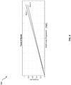
- FIG. 8 illustrates and exemplary trend plot 800 of a first set of peak values 802 associated with the first frequency band 712 and a second set of peak values 804 associated with the second frequency band 714.
- the horizontal x-axis of the trend plot represents time.
- the various peak values can be identified from the coherence calculated as the crack in the shaft progresses (e.g., coherence plots 702, 704, 706, etc.). The progress of the crack in the shaft can occur over a period of time.
- the state of the shaft can be determined by comparing the peak values with multiple predetermined threshold values.
- the peak values e.g., peak values of the two bands 712 and 714
- the peak values can be compared with multiple predetermined threshold values, and a determination can be made regarding the state of the crack in the shaft.
- a determination can be made that the shaft has cracked e.g., as illustrated in plot 706; if the peak value is between the first predetermined threshold value and a second predetermined threshold value (lower than the first predetermined threshold value), a determination can be made that the crack has been initiated in the shaft (e.g., as illustrated in plot 704); and if the peak value is below the second predetermined threshold value, a determination can be made that no cracks exist in the shaft (e.g., as illustrated in plot 702).
- first frequency band 712 and the second frequency band 714 can be used to track coherence in mechanical systems with known cross-coupling mechanisms, such as those that are discussed above. Loss of coherence can indicate a change in machine condition. Combined with other signal processing techniques (e.g., coherence analysis) leading/lagging causality can be established for the cross-coupling. This allows for identification of excitation source (e.g., a determination of lateral forcing function cross coupling into torsional and vice-versa). These methods can be extended to areas including transient analysis, blade pass on pumps, coherence with dynamic pressure, coherence with drive systems, and other processes.
- excitation source e.g., a determination of lateral forcing function cross coupling into torsional and vice-versa
- the first frequency and/or coherence information can be provided (e.g., to a user).
- a plot of the coherence along with the identified frequencies e.g., first frequency, second frequency, etc.
- GUI graphical user interface
- the user can be notified of the state of the shaft (e.g., no crack on the shaft, crack beginning to appear, the shaft has cracked, etc.).
- the subject matter described herein can be implemented in digital electronic circuitry, or in computer software, firmware, or hardware, including the structural means disclosed in this specification and structural equivalents thereof, or in combinations of them.
- the subject matter described herein can be implemented as one or more computer program products, such as one or more computer programs tangibly embodied in an information carrier (e.g., in a machine-readable storage device), or embodied in a propagated signal, for execution by, or to control the operation of, data processing apparatus (e.g., a programmable processor, a computer, or multiple computers).
- a computer program (also known as a program, software, software application, or code) can be written in any form of programming language, including compiled or interpreted languages, and it can be deployed in any form, including as a stand-alone program or as a module, component, subroutine, or other unit suitable for use in a computing environment.
- a computer program does not necessarily correspond to a file.
- a program can be stored in a portion of a file that holds other programs or data, in a single file dedicated to the program in question, or in multiple coordinated files (e.g., files that store one or more modules, sub-programs, or portions of code).
- a computer program can be deployed to be executed on one computer or on multiple computers at one site or distributed across multiple sites and interconnected by a communication network.
- processors suitable for the execution of a computer program include, by way of example, both general and special purpose microprocessors, and any one or more processor of any kind of digital computer.
- a processor will receive instructions and data from a Read-Only Memory or a Random Access Memory or both.
- the essential elements of a computer are a processor for executing instructions and one or more memory devices for storing instructions and data.
- a computer will also include, or be operatively coupled to receive data from or transfer data to, or both, one or more mass storage devices for storing data, e.g., magnetic, magneto-optical disks, or optical disks.
- Information carriers suitable for embodying computer program instructions and data include all forms of non-volatile memory, including by way of example semiconductor memory devices, (e.g., EPROM, EEPROM, and flash memory devices); magnetic disks, (e.g., internal hard disks or removable disks); magneto-optical disks; and optical disks (e.g., CD and DVD disks).
- semiconductor memory devices e.g., EPROM, EEPROM, and flash memory devices
- magnetic disks e.g., internal hard disks or removable disks
- magneto-optical disks e.g., CD and DVD disks
- optical disks e.g., CD and DVD disks.
- the processor and the memory can be supplemented by, or incorporated in, special purpose logic circuitry.
- the subject matter described herein can be implemented on a computer having a display device, e.g., a CRT (cathode ray tube) or LCD (liquid crystal display) monitor, for displaying information to the user and a keyboard and a pointing device, (e.g., a mouse or a trackball), by which the user can provide input to the computer.
- a display device e.g., a CRT (cathode ray tube) or LCD (liquid crystal display) monitor
- a keyboard and a pointing device e.g., a mouse or a trackball
- Other kinds of devices can be used to provide for interaction with a user as well.
- feedback provided to the user can be any form of sensory feedback, (e.g., visual feedback, auditory feedback, or tactile feedback), and input from the user can be received in any form, including acoustic, speech, or tactile input.
- modules refers to computing software, firmware, hardware, and/or various combinations thereof. At a minimum, however, modules are not to be interpreted as software that is not implemented on hardware, firmware, or recorded on a non-transitory processor readable recordable storage medium (i.e., modules are not software per se). Indeed “module” is to be interpreted to always include at least some physical, non-transitory hardware such as a part of a processor or computer. Two different modules can share the same physical hardware (e.g., two different modules can use the same processor and network interface). The modules described herein can be combined, integrated, separated, and/or duplicated to support various applications.
- a function described herein as being performed at a particular module can be performed at one or more other modules and/or by one or more other devices instead of or in addition to the function performed at the particular module.
- the modules can be implemented across multiple devices and/or other components local or remote to one another. Additionally, the modules can be moved from one device and added to another device, and/or can be included in both devices.
- the subject matter described herein can be implemented in a computing system that includes a back-end component (e.g., a data server), a middleware component (e.g., an application server), or a front-end component (e.g., a client computer having a graphical user interface or a web interface through which a user can interact with an implementation of the subject matter described herein), or any combination of such back-end, middleware, and front-end components.
- the components of the system can be interconnected by any form or medium of digital data communication, e.g., a communication network. Examples of communication networks include a local area network ("LAN”) and a wide area network (“WAN”), e.g., the Internet.
- LAN local area network
- WAN wide area network
- Approximating language may be applied to modify any quantitative representation that could permissibly vary without resulting in a change in the basic function to which it is related. Accordingly, a value modified by a term or terms, such as “about” and “substantially,” are not to be limited to the precise value specified. In at least some instances, the approximating language may correspond to the precision of an instrument for measuring the value.
- range limitations may be combined and/or interchanged, such ranges are identified and include all the sub-ranges contained therein unless context or language indicates otherwise.
Landscapes
- Physics & Mathematics (AREA)
- General Physics & Mathematics (AREA)
- Acoustics & Sound (AREA)
- Measurement Of Mechanical Vibrations Or Ultrasonic Waves (AREA)
- Testing Of Devices, Machine Parts, Or Other Structures Thereof (AREA)
Applications Claiming Priority (1)
| Application Number | Priority Date | Filing Date | Title |
|---|---|---|---|
| US202063056158P | 2020-07-24 | 2020-07-24 |
Publications (2)
| Publication Number | Publication Date |
|---|---|
| EP3943898A1 true EP3943898A1 (fr) | 2022-01-26 |
| EP3943898B1 EP3943898B1 (fr) | 2023-12-27 |
Family
ID=77042764
Family Applications (1)
| Application Number | Title | Priority Date | Filing Date |
|---|---|---|---|
| EP21187306.2A Active EP3943898B1 (fr) | 2020-07-24 | 2021-07-22 | Détection de couplage des vibrations torsionnelles et latérales |
Country Status (4)
| Country | Link |
|---|---|
| US (2) | US11592327B2 (fr) |
| EP (1) | EP3943898B1 (fr) |
| CN (1) | CN113970443B (fr) |
| DK (1) | DK3943898T3 (fr) |
Citations (5)
| Publication number | Priority date | Publication date | Assignee | Title |
|---|---|---|---|---|
| US5068800A (en) * | 1989-03-14 | 1991-11-26 | Rem Technologies, Inc. | Crack detection method for shaft at rest |
| WO1992005437A1 (fr) * | 1990-09-19 | 1992-04-02 | Rem Technologies, Inc. | Procede de detection de fissures dans un arbre en fonctionnement |
| CA2192182A1 (fr) * | 1994-04-05 | 1995-10-12 | Walter C. Hernandez | Procede et appareil non-invasifs pour obtenir des informations relatives a la resonance dans des composants de machines tournantes et pour anticiper des defaillances dans ces composants a la suite de changements s'y produisant |
| WO1997032186A1 (fr) * | 1996-02-29 | 1997-09-04 | Monitoring Technology Corporation | Appareil a capteurs multiples et procede de surveillance de turbomachines |
| EP2259033A2 (fr) * | 2009-06-06 | 2010-12-08 | Nuovo Pignone S.p.A. | Surveillance de vibration latérale, angulaire et de torsion de systèmes dynamiques à rotor |
Family Cites Families (12)
| Publication number | Priority date | Publication date | Assignee | Title |
|---|---|---|---|---|
| US5520061A (en) * | 1989-03-14 | 1996-05-28 | Enprotech Corporation | Multiple axis transducer mounting collar |
| US5038614A (en) * | 1989-08-10 | 1991-08-13 | Atlantic Richfield Company | Acoustic vibration detection of fluid leakage from conduits |
| US5949162A (en) * | 1996-12-13 | 1999-09-07 | General Dynamics Advanced Technology Systems, Inc. | Unbalanced force generation in motors |
| US8442688B2 (en) * | 2010-01-28 | 2013-05-14 | Holcim (US), Inc. | System for monitoring plant equipment |
| EP2823272B1 (fr) * | 2012-03-05 | 2020-07-29 | Prysmian S.p.A. | Procédé de détection d'une torsion dans un câble, câble électrique comportant un capteur de torsion et procédé de fabrication dudit câble |
| GB201216529D0 (en) * | 2012-09-17 | 2012-10-31 | Univ St Andrews | Torsional stiffness measurement |
| CN103257010B (zh) * | 2013-04-24 | 2014-11-19 | 中北大学 | 基于电容耦合的旋转件扭矩测试方法 |
| CN104006966B (zh) * | 2014-05-29 | 2016-08-03 | 哈尔滨工程大学 | 载荷对齿轮轴系振动和齿轮箱体振动相互耦合影响规律的实验装置及验证方法 |
| CN107345846B (zh) * | 2017-07-28 | 2019-04-16 | 大连理工大学 | 一种大振幅自由竖向和扭转耦合振动风洞试验装置 |
| US10837864B2 (en) * | 2018-03-05 | 2020-11-17 | Dalian University Of Technology | Large-amplitude vertical-torsional coupled free vibration setup for wind tunnel test |
| CN111207819A (zh) * | 2018-11-22 | 2020-05-29 | 中国船舶重工集团公司第七一一研究所 | 轴系振动测量系统及方法 |
| CN111238761B (zh) * | 2020-02-06 | 2021-01-19 | 大连理工大学 | 扭转和竖弯振动频率比可调的耦合自由振动风洞试验装置 |
-
2021
- 2021-07-22 US US17/382,927 patent/US11592327B2/en active Active
- 2021-07-22 EP EP21187306.2A patent/EP3943898B1/fr active Active
- 2021-07-22 DK DK21187306.2T patent/DK3943898T3/da active
- 2021-07-26 CN CN202110844157.2A patent/CN113970443B/zh active Active
-
2023
- 2023-02-27 US US18/174,721 patent/US20240053192A1/en active Pending
Patent Citations (5)
| Publication number | Priority date | Publication date | Assignee | Title |
|---|---|---|---|---|
| US5068800A (en) * | 1989-03-14 | 1991-11-26 | Rem Technologies, Inc. | Crack detection method for shaft at rest |
| WO1992005437A1 (fr) * | 1990-09-19 | 1992-04-02 | Rem Technologies, Inc. | Procede de detection de fissures dans un arbre en fonctionnement |
| CA2192182A1 (fr) * | 1994-04-05 | 1995-10-12 | Walter C. Hernandez | Procede et appareil non-invasifs pour obtenir des informations relatives a la resonance dans des composants de machines tournantes et pour anticiper des defaillances dans ces composants a la suite de changements s'y produisant |
| WO1997032186A1 (fr) * | 1996-02-29 | 1997-09-04 | Monitoring Technology Corporation | Appareil a capteurs multiples et procede de surveillance de turbomachines |
| EP2259033A2 (fr) * | 2009-06-06 | 2010-12-08 | Nuovo Pignone S.p.A. | Surveillance de vibration latérale, angulaire et de torsion de systèmes dynamiques à rotor |
Non-Patent Citations (1)
| Title |
|---|
| "HARRIS' SHOCK AND VIBRATION HANDBOOK (Fifth Edition )", 1 January 2002, MCGRAW-HILL, US, article CYRIL M. HARRIS ET AL: "HARRIS' SHOCK AND VIBRATION HANDBOOK (Fifth Edition )", pages: 1 - 1456, XP055356679 * |
Also Published As
| Publication number | Publication date |
|---|---|
| US20220026263A1 (en) | 2022-01-27 |
| DK3943898T3 (da) | 2024-02-19 |
| US20240053192A1 (en) | 2024-02-15 |
| CN113970443B (zh) | 2023-10-31 |
| US11592327B2 (en) | 2023-02-28 |
| EP3943898B1 (fr) | 2023-12-27 |
| CN113970443A (zh) | 2022-01-25 |
Similar Documents
| Publication | Publication Date | Title |
|---|---|---|
| Chandra et al. | Fault detection in rotor bearing systems using time frequency techniques | |
| US7082371B2 (en) | Fundamental mistuning model for determining system properties and predicting vibratory response of bladed disks | |
| Sawicki et al. | Detecting cracked rotors using auxiliary harmonic excitation | |
| US5159563A (en) | Crack detection method for operating shaft | |
| JP5694361B2 (ja) | タービンエンジンの回転軸のねじれ振動を監視する方法および装置 | |
| Stoisser et al. | A comprehensive theoretical, numerical and experimental approach for crack detection in power plant rotating machinery | |
| Ishida et al. | Detection of a rotor crack using a harmonic excitation and nonlinear vibration analysis | |
| Presas et al. | On the detection of natural frequencies and mode shapes of submerged rotating disk-like structures from the casing | |
| Kankar et al. | Fault diagnosis of high speed rolling element bearings due to localized defects using response surface method | |
| JP6208699B2 (ja) | 実験モード解析により機械の潤滑特性を計測するサーボ制御装置 | |
| Wan et al. | Compound fault diagnosis of bearings using an improved spectral kurtosis by MCDK | |
| Bai et al. | Adaptive order tracking technique using recursive least-square algorithm | |
| Firrone et al. | On force control of an engine order–type excitation applied to a bladed disk with underplatform dampers | |
| US8396676B2 (en) | Method and device for measuring visco-elastic fluid parameters | |
| EP3943898A1 (fr) | Détection de couplage des vibrations torsionnelles et latérales | |
| Akhtar et al. | High-vibration diagnosis of gas turbines: An experimental investigation | |
| CN111855195A (zh) | 用于齿轮箱的异常检测方法以及信息处理设备 | |
| Rahman et al. | Health Condition Monitoring and Control of Vibrations of a Rotating System through Vibration Analysis | |
| Song et al. | Multispectral balanced automatic fault diagnosis for rolling bearings under variable speed conditions | |
| Cavacece et al. | Analysis of damage of ball bearings of aeronautical transmissions by auto-power spectrum and cross-power spectrum | |
| US11674412B2 (en) | Closed loop control employing magnetostrictive sensing | |
| WO2019220542A1 (fr) | Dispositif de diagnostic d'équipement de roulement et procédé de diagnostic | |
| US11429900B1 (en) | Systems and methods for automatic detection of error conditions in mechanical machines | |
| JP4419561B2 (ja) | モータのトルクリップル測定装置及びトルクリップル測定方法 | |
| US11543325B2 (en) | Monitoring machine vibration |
Legal Events
| Date | Code | Title | Description |
|---|---|---|---|
| PUAI | Public reference made under article 153(3) epc to a published international application that has entered the european phase |
Free format text: ORIGINAL CODE: 0009012 |
|
| STAA | Information on the status of an ep patent application or granted ep patent |
Free format text: STATUS: REQUEST FOR EXAMINATION WAS MADE |
|
| 17P | Request for examination filed |
Effective date: 20210722 |
|
| AK | Designated contracting states |
Kind code of ref document: A1 Designated state(s): AL AT BE BG CH CY CZ DE DK EE ES FI FR GB GR HR HU IE IS IT LI LT LU LV MC MK MT NL NO PL PT RO RS SE SI SK SM TR |
|
| P01 | Opt-out of the competence of the unified patent court (upc) registered |
Effective date: 20230526 |
|
| GRAP | Despatch of communication of intention to grant a patent |
Free format text: ORIGINAL CODE: EPIDOSNIGR1 |
|
| STAA | Information on the status of an ep patent application or granted ep patent |
Free format text: STATUS: GRANT OF PATENT IS INTENDED |
|
| INTG | Intention to grant announced |
Effective date: 20231017 |
|
| GRAS | Grant fee paid |
Free format text: ORIGINAL CODE: EPIDOSNIGR3 |
|
| GRAA | (expected) grant |
Free format text: ORIGINAL CODE: 0009210 |
|
| STAA | Information on the status of an ep patent application or granted ep patent |
Free format text: STATUS: THE PATENT HAS BEEN GRANTED |
|
| AK | Designated contracting states |
Kind code of ref document: B1 Designated state(s): AL AT BE BG CH CY CZ DE DK EE ES FI FR GB GR HR HU IE IS IT LI LT LU LV MC MK MT NL NO PL PT RO RS SE SI SK SM TR |
|
| REG | Reference to a national code |
Ref country code: GB Ref legal event code: FG4D |
|
| REG | Reference to a national code |
Ref country code: CH Ref legal event code: EP |
|
| REG | Reference to a national code |
Ref country code: DE Ref legal event code: R096 Ref document number: 602021008040 Country of ref document: DE |
|
| REG | Reference to a national code |
Ref country code: IE Ref legal event code: FG4D |
|
| REG | Reference to a national code |
Ref country code: DK Ref legal event code: T3 Effective date: 20240215 |
|
| REG | Reference to a national code |
Ref country code: SE Ref legal event code: TRGR |
|
| PG25 | Lapsed in a contracting state [announced via postgrant information from national office to epo] |
Ref country code: GR Free format text: LAPSE BECAUSE OF FAILURE TO SUBMIT A TRANSLATION OF THE DESCRIPTION OR TO PAY THE FEE WITHIN THE PRESCRIBED TIME-LIMIT Effective date: 20240328 |
|
| REG | Reference to a national code |
Ref country code: LT Ref legal event code: MG9D |
|
| PG25 | Lapsed in a contracting state [announced via postgrant information from national office to epo] |
Ref country code: LT Free format text: LAPSE BECAUSE OF FAILURE TO SUBMIT A TRANSLATION OF THE DESCRIPTION OR TO PAY THE FEE WITHIN THE PRESCRIBED TIME-LIMIT Effective date: 20231227 |
|
| PG25 | Lapsed in a contracting state [announced via postgrant information from national office to epo] |
Ref country code: ES Free format text: LAPSE BECAUSE OF FAILURE TO SUBMIT A TRANSLATION OF THE DESCRIPTION OR TO PAY THE FEE WITHIN THE PRESCRIBED TIME-LIMIT Effective date: 20231227 |
|
| PG25 | Lapsed in a contracting state [announced via postgrant information from national office to epo] |
Ref country code: LT Free format text: LAPSE BECAUSE OF FAILURE TO SUBMIT A TRANSLATION OF THE DESCRIPTION OR TO PAY THE FEE WITHIN THE PRESCRIBED TIME-LIMIT Effective date: 20231227 Ref country code: GR Free format text: LAPSE BECAUSE OF FAILURE TO SUBMIT A TRANSLATION OF THE DESCRIPTION OR TO PAY THE FEE WITHIN THE PRESCRIBED TIME-LIMIT Effective date: 20240328 Ref country code: FI Free format text: LAPSE BECAUSE OF FAILURE TO SUBMIT A TRANSLATION OF THE DESCRIPTION OR TO PAY THE FEE WITHIN THE PRESCRIBED TIME-LIMIT Effective date: 20231227 Ref country code: ES Free format text: LAPSE BECAUSE OF FAILURE TO SUBMIT A TRANSLATION OF THE DESCRIPTION OR TO PAY THE FEE WITHIN THE PRESCRIBED TIME-LIMIT Effective date: 20231227 Ref country code: BG Free format text: LAPSE BECAUSE OF FAILURE TO SUBMIT A TRANSLATION OF THE DESCRIPTION OR TO PAY THE FEE WITHIN THE PRESCRIBED TIME-LIMIT Effective date: 20240327 |
|
| REG | Reference to a national code |
Ref country code: NL Ref legal event code: MP Effective date: 20231227 |
|
| REG | Reference to a national code |
Ref country code: AT Ref legal event code: MK05 Ref document number: 1644931 Country of ref document: AT Kind code of ref document: T Effective date: 20231227 |
|
| PG25 | Lapsed in a contracting state [announced via postgrant information from national office to epo] |
Ref country code: NL Free format text: LAPSE BECAUSE OF FAILURE TO SUBMIT A TRANSLATION OF THE DESCRIPTION OR TO PAY THE FEE WITHIN THE PRESCRIBED TIME-LIMIT Effective date: 20231227 |
|
| PG25 | Lapsed in a contracting state [announced via postgrant information from national office to epo] |
Ref country code: RS Free format text: LAPSE BECAUSE OF FAILURE TO SUBMIT A TRANSLATION OF THE DESCRIPTION OR TO PAY THE FEE WITHIN THE PRESCRIBED TIME-LIMIT Effective date: 20231227 Ref country code: NO Free format text: LAPSE BECAUSE OF FAILURE TO SUBMIT A TRANSLATION OF THE DESCRIPTION OR TO PAY THE FEE WITHIN THE PRESCRIBED TIME-LIMIT Effective date: 20240327 Ref country code: NL Free format text: LAPSE BECAUSE OF FAILURE TO SUBMIT A TRANSLATION OF THE DESCRIPTION OR TO PAY THE FEE WITHIN THE PRESCRIBED TIME-LIMIT Effective date: 20231227 Ref country code: LV Free format text: LAPSE BECAUSE OF FAILURE TO SUBMIT A TRANSLATION OF THE DESCRIPTION OR TO PAY THE FEE WITHIN THE PRESCRIBED TIME-LIMIT Effective date: 20231227 Ref country code: HR Free format text: LAPSE BECAUSE OF FAILURE TO SUBMIT A TRANSLATION OF THE DESCRIPTION OR TO PAY THE FEE WITHIN THE PRESCRIBED TIME-LIMIT Effective date: 20231227 |
|
| PG25 | Lapsed in a contracting state [announced via postgrant information from national office to epo] |
Ref country code: IS Free format text: LAPSE BECAUSE OF FAILURE TO SUBMIT A TRANSLATION OF THE DESCRIPTION OR TO PAY THE FEE WITHIN THE PRESCRIBED TIME-LIMIT Effective date: 20240427 |
|
| PGFP | Annual fee paid to national office [announced via postgrant information from national office to epo] |
Ref country code: DK Payment date: 20240619 Year of fee payment: 4 |
|
| PG25 | Lapsed in a contracting state [announced via postgrant information from national office to epo] |
Ref country code: CZ Free format text: LAPSE BECAUSE OF FAILURE TO SUBMIT A TRANSLATION OF THE DESCRIPTION OR TO PAY THE FEE WITHIN THE PRESCRIBED TIME-LIMIT Effective date: 20231227 Ref country code: AT Free format text: LAPSE BECAUSE OF FAILURE TO SUBMIT A TRANSLATION OF THE DESCRIPTION OR TO PAY THE FEE WITHIN THE PRESCRIBED TIME-LIMIT Effective date: 20231227 |
|
| PG25 | Lapsed in a contracting state [announced via postgrant information from national office to epo] |
Ref country code: SK Free format text: LAPSE BECAUSE OF FAILURE TO SUBMIT A TRANSLATION OF THE DESCRIPTION OR TO PAY THE FEE WITHIN THE PRESCRIBED TIME-LIMIT Effective date: 20231227 |
|
| PG25 | Lapsed in a contracting state [announced via postgrant information from national office to epo] |
Ref country code: SM Free format text: LAPSE BECAUSE OF FAILURE TO SUBMIT A TRANSLATION OF THE DESCRIPTION OR TO PAY THE FEE WITHIN THE PRESCRIBED TIME-LIMIT Effective date: 20231227 Ref country code: SK Free format text: LAPSE BECAUSE OF FAILURE TO SUBMIT A TRANSLATION OF THE DESCRIPTION OR TO PAY THE FEE WITHIN THE PRESCRIBED TIME-LIMIT Effective date: 20231227 Ref country code: RO Free format text: LAPSE BECAUSE OF FAILURE TO SUBMIT A TRANSLATION OF THE DESCRIPTION OR TO PAY THE FEE WITHIN THE PRESCRIBED TIME-LIMIT Effective date: 20231227 Ref country code: IT Free format text: LAPSE BECAUSE OF FAILURE TO SUBMIT A TRANSLATION OF THE DESCRIPTION OR TO PAY THE FEE WITHIN THE PRESCRIBED TIME-LIMIT Effective date: 20231227 Ref country code: IS Free format text: LAPSE BECAUSE OF FAILURE TO SUBMIT A TRANSLATION OF THE DESCRIPTION OR TO PAY THE FEE WITHIN THE PRESCRIBED TIME-LIMIT Effective date: 20240427 Ref country code: EE Free format text: LAPSE BECAUSE OF FAILURE TO SUBMIT A TRANSLATION OF THE DESCRIPTION OR TO PAY THE FEE WITHIN THE PRESCRIBED TIME-LIMIT Effective date: 20231227 Ref country code: CZ Free format text: LAPSE BECAUSE OF FAILURE TO SUBMIT A TRANSLATION OF THE DESCRIPTION OR TO PAY THE FEE WITHIN THE PRESCRIBED TIME-LIMIT Effective date: 20231227 Ref country code: AT Free format text: LAPSE BECAUSE OF FAILURE TO SUBMIT A TRANSLATION OF THE DESCRIPTION OR TO PAY THE FEE WITHIN THE PRESCRIBED TIME-LIMIT Effective date: 20231227 |
|
| PG25 | Lapsed in a contracting state [announced via postgrant information from national office to epo] |
Ref country code: PL Free format text: LAPSE BECAUSE OF FAILURE TO SUBMIT A TRANSLATION OF THE DESCRIPTION OR TO PAY THE FEE WITHIN THE PRESCRIBED TIME-LIMIT Effective date: 20231227 Ref country code: PT Free format text: LAPSE BECAUSE OF FAILURE TO SUBMIT A TRANSLATION OF THE DESCRIPTION OR TO PAY THE FEE WITHIN THE PRESCRIBED TIME-LIMIT Effective date: 20240429 |
|
| PG25 | Lapsed in a contracting state [announced via postgrant information from national office to epo] |
Ref country code: PT Free format text: LAPSE BECAUSE OF FAILURE TO SUBMIT A TRANSLATION OF THE DESCRIPTION OR TO PAY THE FEE WITHIN THE PRESCRIBED TIME-LIMIT Effective date: 20240429 Ref country code: PL Free format text: LAPSE BECAUSE OF FAILURE TO SUBMIT A TRANSLATION OF THE DESCRIPTION OR TO PAY THE FEE WITHIN THE PRESCRIBED TIME-LIMIT Effective date: 20231227 |
|
| PGFP | Annual fee paid to national office [announced via postgrant information from national office to epo] |
Ref country code: SE Payment date: 20240619 Year of fee payment: 4 |