EP3943395A1 - Environmental control system for use in an aircraft - Google Patents
Environmental control system for use in an aircraft Download PDFInfo
- Publication number
- EP3943395A1 EP3943395A1 EP21185437.7A EP21185437A EP3943395A1 EP 3943395 A1 EP3943395 A1 EP 3943395A1 EP 21185437 A EP21185437 A EP 21185437A EP 3943395 A1 EP3943395 A1 EP 3943395A1
- Authority
- EP
- European Patent Office
- Prior art keywords
- aircraft
- decompression panel
- apertures
- panel assembly
- array
- Prior art date
- Legal status (The legal status is an assumption and is not a legal conclusion. Google has not performed a legal analysis and makes no representation as to the accuracy of the status listed.)
- Granted
Links
Images


Classifications
-
- B—PERFORMING OPERATIONS; TRANSPORTING
- B64—AIRCRAFT; AVIATION; COSMONAUTICS
- B64D—EQUIPMENT FOR FITTING IN OR TO AIRCRAFT; FLIGHT SUITS; PARACHUTES; ARRANGEMENT OR MOUNTING OF POWER PLANTS OR PROPULSION TRANSMISSIONS IN AIRCRAFT
- B64D13/00—Arrangements or adaptations of air-treatment apparatus for aircraft crew or passengers, or freight space
- B64D13/06—Arrangements or adaptations of air-treatment apparatus for aircraft crew or passengers, or freight space the air being conditioned
-
- B—PERFORMING OPERATIONS; TRANSPORTING
- B64—AIRCRAFT; AVIATION; COSMONAUTICS
- B64C—AEROPLANES; HELICOPTERS
- B64C1/00—Fuselages; Constructional features common to fuselages, wings, stabilising surfaces or the like
- B64C2001/009—Fuselages; Constructional features common to fuselages, wings, stabilising surfaces or the like comprising decompression panels or valves for pressure equalisation in fuselages or floors
-
- B—PERFORMING OPERATIONS; TRANSPORTING
- B64—AIRCRAFT; AVIATION; COSMONAUTICS
- B64D—EQUIPMENT FOR FITTING IN OR TO AIRCRAFT; FLIGHT SUITS; PARACHUTES; ARRANGEMENT OR MOUNTING OF POWER PLANTS OR PROPULSION TRANSMISSIONS IN AIRCRAFT
- B64D13/00—Arrangements or adaptations of air-treatment apparatus for aircraft crew or passengers, or freight space
- B64D13/06—Arrangements or adaptations of air-treatment apparatus for aircraft crew or passengers, or freight space the air being conditioned
- B64D2013/0603—Environmental Control Systems
-
- B—PERFORMING OPERATIONS; TRANSPORTING
- B64—AIRCRAFT; AVIATION; COSMONAUTICS
- B64D—EQUIPMENT FOR FITTING IN OR TO AIRCRAFT; FLIGHT SUITS; PARACHUTES; ARRANGEMENT OR MOUNTING OF POWER PLANTS OR PROPULSION TRANSMISSIONS IN AIRCRAFT
- B64D13/00—Arrangements or adaptations of air-treatment apparatus for aircraft crew or passengers, or freight space
- B64D13/06—Arrangements or adaptations of air-treatment apparatus for aircraft crew or passengers, or freight space the air being conditioned
- B64D2013/0603—Environmental Control Systems
- B64D2013/0625—Environmental Control Systems comprising means for distribution effusion of conditioned air in the cabin
-
- B—PERFORMING OPERATIONS; TRANSPORTING
- B64—AIRCRAFT; AVIATION; COSMONAUTICS
- B64D—EQUIPMENT FOR FITTING IN OR TO AIRCRAFT; FLIGHT SUITS; PARACHUTES; ARRANGEMENT OR MOUNTING OF POWER PLANTS OR PROPULSION TRANSMISSIONS IN AIRCRAFT
- B64D13/00—Arrangements or adaptations of air-treatment apparatus for aircraft crew or passengers, or freight space
- B64D13/06—Arrangements or adaptations of air-treatment apparatus for aircraft crew or passengers, or freight space the air being conditioned
- B64D2013/0603—Environmental Control Systems
- B64D2013/0651—Environmental Control Systems comprising filters, e.g. dust filters
-
- B—PERFORMING OPERATIONS; TRANSPORTING
- B64—AIRCRAFT; AVIATION; COSMONAUTICS
- B64D—EQUIPMENT FOR FITTING IN OR TO AIRCRAFT; FLIGHT SUITS; PARACHUTES; ARRANGEMENT OR MOUNTING OF POWER PLANTS OR PROPULSION TRANSMISSIONS IN AIRCRAFT
- B64D13/00—Arrangements or adaptations of air-treatment apparatus for aircraft crew or passengers, or freight space
- B64D13/06—Arrangements or adaptations of air-treatment apparatus for aircraft crew or passengers, or freight space the air being conditioned
- B64D2013/0603—Environmental Control Systems
- B64D2013/0688—Environmental Control Systems with means for recirculating cabin air
Definitions
- the field of the present disclosure relates generally to environmental control systems and, more specifically, to environmental control systems that limit airflow forward and aftward through adjacent passenger aisles.
- an environmental control system One purpose of an environmental control system is to distribute air through the main passenger cabin of the aircraft.
- air is supplied through ducts in the cabin ceiling and then flows through return air grills located near the cabin floor in the sidewall of each aisle.
- the return air grills are built into decompression panel assemblies and are identical to each other along the cabin such that each return air grill provides a substantially similar airflow restriction therethrough.
- At least some known environmental control systems also include various components, such as filters, fans, and air conditioning packs that draw air through the return air grills. These components are positioned at various locations along the aircraft and so they draw air primarily through the return air grills from the aisles around which the component is located.
- each of the return air grills have a similar flow restriction, there tends to be a cross-aisle airflow in the aft or forward direction toward the nearest component of the environmental control system drawing air through the return air grills.
- the airflow entering the return air grills in the aisle nearest the drawing component may have passed through one or more adjacent aisles, thus exposing the passengers in the component aisle to more cross-aisle airflow than passengers seated in aisle further from the drawing component of the environmental control system.
- an environmental control system for use in an aircraft.
- the environmental control system includes at least one component positioned along a length of the aircraft and a decompression panel assembly comprising an array of apertures.
- the array of apertures is based on a location of the decompression panel assembly along the length of the aircraft relative to the at least one component
- an aircraft in another aspect, includes a first aisle including a first decompression panel assembly having a first array of apertures that define a first airflow restriction.
- the aircraft also includes a second aisle including a second decompression panel assembly having a second array of apertures that define a second airflow restriction different than the first airflow restriction.
- a decompression panel assembly for use in an aircraft.
- the decompression panel assembly includes a frame, a housing including a rear wall that is spaced from the frame, and a pair of decompression panels coupled to the rear wall and extending toward the frame.
- a decompression panel assembly for use in an aircraft having an environmental control system.
- the decompression panel assembly includes a housing that defines a chamber and an insert configured to be positioned within the chamber.
- the insert includes an array of apertures configured to provide a predetermined airflow restriction through the decompression panel assembly.
- the array of apertures is based on a location of the decompression panel assembly along a length of the aircraft.
- Example systems described below include an environmental control system that facilitates minimizing airflow between passengers within confined spaces, such as aircraft passenger cabins.
- Example systems described provide decompression panel assemblies that include different flow restrictions based on their location along the length of the aircraft and proximity to other components of the environmental control system.
- the aircraft includes a first aisle having a first decompression panel assembly with a first array of apertures that define a first airflow restriction.
- a second aisle includes a second decompression panel assembly having a second array of apertures that define a second airflow restriction different than the first airflow restriction.
- the different air flow restrictions are configured to provide a substantially similar mass flow through both the decompression panel assemblies.
- Example systems facilitate reducing the spread of airborne contaminants between nearby occupants, reducing noise and undesirable drafts, and limiting the formation of stagnant zones of circulation within the confined space.
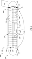
- FIG. 1 is a cross-sectional view of an aircraft 100 having an example environmental control system (ECS) 102.
- Aircraft 100 includes a forward end 104, an aft end 106, and a passenger cabin 108 extending therebetween.
- Cabin 108 is separated from a lower lobe 110 of aircraft 100 by a cabin floor 112.
- ECS 102 circulates air through cabin 108 to provide the passengers with cool, clean air.
- ECS 102 includes a main distribution duct 114 defined in the crown volume 116 above cabin 108. From main distribution duct 114, air is channeled to each row or aisle 118 in cabin 108 such that a generally uniform distribution air airflow is distributed to cabin 108 from main distribution duct 114.
- ECS 102 includes a variety of components 122 located in lower lobe 110 that draw air from cabin 108 through a return air grill defined in a decompression panel assembly 120 in each aisle 118. More specifically, components 122 include a cooling filter 124 positioned proximate forward end 104. A recirculation filter 126, a mixing manifold 128, and at least one air conditioning pack 130 are positioned proximate a wing box 132 of aircraft 100. Additionally, an outlet valve 134 is positioned at aft end 106. Generally, components 122 are positioned along the length of the aircraft 100 between forward end 104 and aft end 106 at any location that facilitates operation of ECS 102 as described herein.
- each component 122 of ECS 102 draws air through decompression panel assemblies 120.
- the pressure of the draw or suction force 136 through each decompression panel assembly 120 will vary based on its location relative to one of components 122.
- decompression panel assemblies 120 closest to each component will have a higher suction or draw force because of the close proximity.
- cooling filter 124 and outlet valve 134 exert a higher draw force on decompression panel assemblies in aisles 118 at forward end 104 and aft end 106, respectively.
- recirculation filter 126 and air conditioning pack 130 cause a higher suction force at decompression panel assemblies 120 in aisles 118 closer thereto.
- FIG. 1 illustrates the suction force through decompression panel assemblies 120 in aisles 118 that are distanced from components 122. This idea is illustrated in FIG. 1 by showing the suction force of selected aisles in broken lines. The thicker and denser the line, the higher the suction force on the corresponding decompression panel assembly 120.
- FIG. 2 is a schematic view of ECS 102 illustrating example decompression panel assemblies 120. More specifically, FIG. 2 is a schematic illustration of a first aisle 118A having a first decompression panel 120A, a second aisle 118B having a second decompression panel 120B; and a third aisle 118C having a third decompression panel 120C. As described above, each aisle 118A, 188B, and 118C has a different suction force, ⁇ P, due to its proximity to various components of ECS 102. Specifically, aisles 118A and 118C have higher suction forces ⁇ P A and ⁇ P c due to their relative proximity to cooling filter 124 and recirculation filter 126.
- Aisle 118B has a lower suction force ⁇ P c because it is spaced further from cooling filter 124 and recirculation filter 126. Additionally, each aisle 118A, 118B, and 118C has a constant structure flow restriction ⁇ R through lower lobe 110.
- each decompression panel assembly 120 may have a different airflow restriction constant K. More specifically, decompression panel assemblies 120 positioned closer to components 122 of ECS 102 include an airflow restriction constant K that is higher than decompression panel assemblies 120 spaced from components 122. For example, referring to FIG.
- the relatively higher suction force ⁇ P A in aisle 118A means that decompression panel 120A will have a higher airflow restriction constant K A than airflow restriction constant K B of decompression panel 120B in aisle 120B, which is subjected a lower suction force ⁇ P B .
- the difference in airflow restriction constants K A and K B result in the mass flow ⁇ A through decompression panel assembly 120A of aisle 118A being substantially similar to the mass flow ⁇ B through decompression panel assembly 120B of aisle 118B.
- the airflow restriction constant Kc of decompression panel 120C is tailored such that the mass flow mc through decompression panel assembly 120C of aisle 118C is substantially similar to the mass flows ⁇ A and ⁇ B .
- the airflow restriction constant K of each decompression panel assembly 120 is tailored based on its location along aircraft and proximity to components 122 of ECS 102 such that the mass flow m of aisles 118A, 118B, and 118C are substantially similar.
- the decompression panel assembly 120 at least partially separates from a frame or grill (not shown) to allow a higher mass flow of air therethrough.
- each decompression panel assembly 120 includes a predetermined array 138 of apertures 140 that provide that decompression panel assembly 120 with a predetermined airflow restriction constant K that will combine with the suction force ⁇ P at the location of the decompression panel assembly 120 to result in a mass flow m substantially similar to the mass flows m of each other aisle 118. As described herein, when each aisle 118 has a substantially similar mass flow m, cross-aisle airflow is reduced or prevented.
- FIG. 3A illustrates a decompression panel assembly 142 having a first array 138A.
- FIG. 3B illustrates a decompression panel assembly 144 having a second array 138B.
- the number, location, and configuration of arrays 138A and 138B are based on the location of decompression panel assemblies 142 and 144 along aircraft 100.
- the location along aircraft 100 determines the proximity to one of components 122 of ECS 102 and the corresponding suction force associated therewith.
- decompression panel assemblies 120 located closer to components 122 will generally have an array 138 with a lower number of apertures 140
- decompression panel assemblies 120 located farther from components 122 will generally have an array 138 with a higher number of apertures 140.
- decompression panel assemblies 120 may have an array 138 with any number of apertures 140 positioned anywhere on decompression panel assembly 120, and in any configuration to facilitate substantially similar mass flows and operation of ECS 102 as described herein.
- decompression panel assemblies 142 and 144 are manufactured with corresponding arrays 138A and 138B, while the remainder of the panel is solid material.
- a decompression panel assembly 146 is manufactured with a plurality of perforations 148 that define apertures 140 once they are removed.
- decompression panel assemblies 146 are manufactured identical to one another and then modified once its position in aircraft 100 is determined. Specifically, once the location is determined, a technician can remove the tabs defined by perforations 148 to provide the decompression panel assembly 1146 with a predetermined array 138 of apertures 140 that correspond to the determined location.
- FIG. 5 is a front perspective view of an alternative decompression panel assembly 200 that may be used in ECS 102 (shown in FIG. 1 ).
- FIG 6 is a rear perspective view of decompression panel assembly 200.
- decompression panel assembly 200 includes a housing 202, a frame 204 coupled to housing 202, and an inlet grill 206 coupled to frame 204.
- inlet grill 206 is coupled to housing 202.
- Housing 202 includes at least a top wall 208 and a rear wall 210.
- Decompression panel assembly 200 also includes a pair of decompression flaps 212 pivotably coupled to rear wall 210 via a hinge 214.
- each decompression flap 212 extends between rear wall 210 and one of inlet grill 206 or frame 204 at an oblique angle such that decompression panel assembly 200 is substantially trapezoidal.
- FIG. 7 is a top cross-sectional view of decompression panel assembly 200.
- housing 202 includes a first inner wall 216, a second inner wall 218, and a plurality of guide vanes 220.
- Inner walls 216 and 218 combine with rear wall 210 to form a chamber 222 that receives airflow through inlet grill 206. More specifically, in normal operation (that is, not during decompression) a return airflow flows through a portion (shown in FIG. 8 ) of inlet grill 206, into chamber 222, and is pulled down through chamber 222 by components 122 of ECS 102.
- decompression flaps 212 are in a closed position, as illustrated by solid lines in FIG.
- decompression flaps 212 open to abut against a sidewall interior 226 and to allow airflow through decompression panel assembly 200.
- guide vanes 220 direct the incoming airflow at an oblique angle with respect to the angle of the airflow through inlet grill 206. Changing the direction of the airflow prevents recirculation back through inlet grill 206 and into cabin 108.
- FIG. 8 is a side cross-sectional view of decompression panel assembly 200
- FIG. 9 is another side cross-sectional view of decompression panel assembly 200 illustrating a pair of example inserts 228.
- decompression panel assembly 200 includes an insert 228 positioned within chamber 222 and configured to provide a predetermined flow restriction to the airflow flowing therethrough based on the location of the insert 228 along the length of aircraft 100 and the proximity of insert 228 to various components 122 of ECS 102.
- Insert 228 is removably coupled to housing 202 and/or inlet grill 206. More specifically, insert 228 is mechanically coupled to at least one wall 210, 216, and 218 of housing 202 with a fastening mechanism 229. For example, insert 228 may be friction fit, attach with fastening mechanism 229, such as a latch, or slide into a slot defined in chamber 222. Generally, insert 228 is coupling within chamber 222 by any means that facilitates operation of decompression panel assembly 200 as described herein.
- decompression panel assemblies 200 closest to each component 122 of ECS 102 will have a higher suction or draw force, also known as a differential pressure, because of the close proximity.
- suction or draw force also known as a differential pressure
- the mass flow through each decompression panel 200, and each insert 228, specifically, should be the same.
- each decompression panel assembly 200 may have a different airflow restriction based on its location along the length of the aircraft. More specifically, decompression panel assemblies 200 positioned closer to components 122 of ECS 102 include an airflow restriction that is higher than decompression panel assemblies 200 spaced from components 122.
- each decompression panel assembly 200 includes an insert 228 having a predetermined array 234 of apertures 232 that provide that particular decompression panel assembly 200 with a predetermined airflow restriction that will combine with the suction force at the location of the decompression panel assembly 200 to result in a mass flow substantially similar to the mass flows of each other aisle 118. As described herein, when each aisle 118 has a substantially similar mass flow, cross-aisle airflow is reduced or prevented.
- FIG. 9 illustrates a decompression panel assembly 200 and a pair of interchangeable inserts 228A and 229B that each include a predetermined aperture array 234A and 234B, respectively.
- the number, location, and configuration of arrays 234A and 234B are based on the location of decompression panel assembly 200 along aircraft 100.
- the location along aircraft 100 determines the proximity to one of components 122 of ECS 102 and the corresponding suction force associated therewith.
- decompression panel assemblies 200 located closer to components 122 will generally have an array 234 with a lower number of apertures 232
- decompression panel assemblies 200 located farther from components 122 will generally have an array 234 with a higher number of apertures 232.
- decompression panel assemblies 200 may have an array 234 with any number of apertures 232 positioned anywhere on decompression panel assembly 200, and in any configuration to facilitate substantially similar mass flows and operation of ECS 102 as described herein.
- inserts 238 allows for all decompression panel assemblies 200 to be manufactured independent of the final location of the decompression panel assembly 200 on the aircraft 100. Once the location of a particular decompression panel assembly 200 is determined, a corresponding insert 228 can be positioned within chamber 222 that provides the decompression panel assembly 200 with the predetermined airflow restriction that combines with the suction force of components 122 to result in a mass flow substantially similar to mass flows of decompression panel assemblies 200 of surrounding aisles 118.
- Example systems described below include an environmental control system that facilitates minimizing airflow between passengers within confined spaces, such as aircraft passenger cabins.
- Example systems described provide decompression panel assemblies that include different flow restrictions based on their location along the length of the aircraft and proximity to other components of the environmental control system.
- the aircraft includes a first aisle having a first decompression panel assembly with a first array of apertures that define a first airflow restriction.
- a second aisle includes a second decompression panel assembly having a second array of apertures that define a second airflow restriction different than the first airflow restriction.
- the different air flow restrictions are configured to provide a substantially similar mass flow through both the decompression panel assemblies.
- Example systems facilitate reducing the spread of airborne contaminants between nearby occupants, reducing noise and undesirable drafts, and limiting the formation of stagnant zones of circulation within the confined space.
Landscapes
- Health & Medical Sciences (AREA)
- General Health & Medical Sciences (AREA)
- Pulmonology (AREA)
- Engineering & Computer Science (AREA)
- Aviation & Aerospace Engineering (AREA)
- Ventilation (AREA)
Abstract
Description
- The field of the present disclosure relates generally to environmental control systems and, more specifically, to environmental control systems that limit airflow forward and aftward through adjacent passenger aisles.
- One purpose of an environmental control system is to distribute air through the main passenger cabin of the aircraft. Generally, air is supplied through ducts in the cabin ceiling and then flows through return air grills located near the cabin floor in the sidewall of each aisle. In many known configurations, the return air grills are built into decompression panel assemblies and are identical to each other along the cabin such that each return air grill provides a substantially similar airflow restriction therethrough. At least some known environmental control systems also include various components, such as filters, fans, and air conditioning packs that draw air through the return air grills. These components are positioned at various locations along the aircraft and so they draw air primarily through the return air grills from the aisles around which the component is located. Because each of the return air grills have a similar flow restriction, there tends to be a cross-aisle airflow in the aft or forward direction toward the nearest component of the environmental control system drawing air through the return air grills. In such a configuration, the airflow entering the return air grills in the aisle nearest the drawing component may have passed through one or more adjacent aisles, thus exposing the passengers in the component aisle to more cross-aisle airflow than passengers seated in aisle further from the drawing component of the environmental control system.
- This section is intended to introduce the reader to various aspects of art that may be related to various aspects of the disclosure, which are described and/or claimed below. This discussion is believed to be helpful in providing the reader with background information to facilitate a better understanding of the various aspects of the present disclosure. Accordingly, it should be understood that these statements are to be read in this light, and not as admissions of prior art.
- In one aspect, an environmental control system for use in an aircraft is provided. The environmental control system includes at least one component positioned along a length of the aircraft and a decompression panel assembly comprising an array of apertures. The array of apertures is based on a location of the decompression panel assembly along the length of the aircraft relative to the at least one component
- In another aspect, an aircraft is provided. The aircraft includes a first aisle including a first decompression panel assembly having a first array of apertures that define a first airflow restriction. The aircraft also includes a second aisle including a second decompression panel assembly having a second array of apertures that define a second airflow restriction different than the first airflow restriction.
- In yet another aspect, a decompression panel assembly for use in an aircraft is provided. The decompression panel assembly includes a frame, a housing including a rear wall that is spaced from the frame, and a pair of decompression panels coupled to the rear wall and extending toward the frame.
- In yet another aspect, a decompression panel assembly for use in an aircraft having an environmental control system is provided. The decompression panel assembly includes a housing that defines a chamber and an insert configured to be positioned within the chamber. The insert includes an array of apertures configured to provide a predetermined airflow restriction through the decompression panel assembly. The array of apertures is based on a location of the decompression panel assembly along a length of the aircraft.
- Various refinements exist of the features noted in relation to the above-mentioned aspects of the present disclosure. Further features may also be incorporated in the above-mentioned aspects of the present disclosure as well. These refinements and additional features may exist individually or in any combination. For instance, various features discussed below in relation to any of the illustrated embodiments of the present disclosure may be incorporated into any of the above-described aspects of the present disclosure, alone or in any combination.
Further embodiments are described in the following examples: - Example 1. An environmental control system for use in an aircraft, the environmental control system comprising:
- at least one component positioned along a length of the aircraft; and
- a decompression panel assembly comprising an array of apertures, wherein the array is based on a location of the decompression panel assembly along the length of the aircraft relative to the at least one component.
- Example 2. The environmental control system in accordance with Example 1, wherein the array of apertures comprises a greater number of apertures the farther the decompression panel assembly is located from the component along the length of the aircraft.
- Example 3. The environmental control system in accordance with Example 1, wherein the array of apertures comprises a smaller number of apertures the closer the decompression panel assembly is located to the component along the length of the aircraft.
- Example 4. An aircraft comprising:
- a first aisle comprising a first decompression panel assembly having a first array of apertures that define a first airflow restriction; and
- a second aisle comprising a second decompression panel assembly having a second array of apertures that define a second airflow restriction different than the first airflow restriction.
- Example 5. The aircraft in accordance with Example 4 further comprising an environmental control system comprising a component configured to provide a first suction force through the first decompression panel assembly and a second suction force through the second decompression panel assembly.
- Example 6. The aircraft in accordance with Example 5, wherein the first decompression panel assembly is positioned a first distance from the component and the second decompression panel assembly is positioned a second, longer distance from the component.
- Example 7. The aircraft in accordance with Example 6, wherein the first and the second airflow restrictions are based on a proximity to the component along a length of the aircraft.
- Example 8. The aircraft in accordance with Example 6, wherein the first suction force is larger than the second suction force.
- Example 9. The aircraft in accordance with Example 4, wherein the first airflow restriction is configured to provide a first mass flow of air through the first decompression panel assembly, wherein the second airflow restriction is configured to provide a second mass flow of air through the second decompression panel assembly, wherein the first mass flow and the second mass flow are substantially similar.
- Example 10. The aircraft in accordance with Example 4, wherein the first airflow restriction is greater than the second airflow restriction.
- Example 11. The aircraft in accordance with Example 4, wherein the first and the second airflow restrictions are based on a location of the first aisle and the second aisle along a length of the aircraft.
- Example 12. The aircraft in accordance with Example 11, wherein the first airflow restriction comprises a first array having a first number of apertures, and wherein the second airflow restriction comprises a second array having a second number of apertures greater than the first number of apertures.
- Example 13. The aircraft in accordance with Example 4, wherein the first and second airflow restrictions comprise an array of a plurality of apertures.
- Example 14. The aircraft in accordance with Example 4, wherein the first and second airflow restrictions comprise an array of a plurality of apertures formed on interchangeable inserts.
- Example 15. The aircraft in accordance with Example 14, wherein the inserts are configured to be positioned within a chamber defined by the decompression panel assembly.
- Example 16. A decompression panel assembly for use in an aircraft, the decompression panel assembly comprising:
- a frame;
- a housing comprising a rear wall that is spaced from the frame; and
- a pair of decompression panels coupled to the rear wall and extending toward the frame.
- Example 17. The decompression panel assembly in accordance with Example 16, wherein the pair of decompression panels are pivotably coupled to the rear wall via a hinge.
- Example 18. The decompression panel assembly in accordance with Example 16, wherein the pair of decompression panels extend obliquely toward the frame with respect to the rear wall.
- Example 19. The decompression panel assembly in accordance with Example 16, wherein the pair of decompression panels are configured to pivot with respect to the rear wall during a decompression event.
- Example 20. The decompression panel assembly in accordance with Example 16, further comprising an inlet grill and a plurality of guide vanes configured to channel an airflow channeled through the inlet grill.
- Example 21. The decompression panel assembly in accordance with Example 20, wherein the plurality of guide vanes are obliquely oriented with respect to the inlet grill and the rear wall.
- Example 22. The decompression panel assembly in accordance with Example 16, wherein the rear wall at least partially defines a chamber within the housing.
- Example 23. The decompression panel assembly in accordance with Example 22, further comprising an insert configured to be positioned within the chamber to provide a predetermined airflow restriction through the decompression panel assembly.
- Example 24. The decompression panel assembly in accordance with Example 23, wherein the airflow restriction comprises an array of apertures formed in the insert, wherein the array of apertures is based on a location of the decompression panel assembly along a length of the aircraft.
- Example 25. A decompression panel assembly for use in an aircraft having an environmental control system, the decompression panel assembly comprising:
- a housing that defines a chamber;
- an insert configured to be positioned within the chamber and comprising an array of apertures configured to provide a predetermined airflow restriction through the decompression panel assembly, wherein the array of apertures is based on a location of the decompression panel assembly along a length of the aircraft.
- Example 26. The decompression panel assembly in accordance with Example 25, wherein the insert is interchangeable with a second insert having a different array of apertures that provide a different airflow restriction.
- Example 27. The decompression panel assembly in accordance with Example 25, wherein the environmental control system comprises at least one component positioned along a length of the aircraft, and wherein the array of apertures comprises a greater number of apertures the farther the insert is located from the component along the length of the aircraft.
- Example 28. The decompression panel assembly in accordance with Example 27, wherein the array of apertures comprises a smaller number of apertures the closer the insert is located to the component along the length of the aircraft.
- Example 29. The aircraft in accordance with Example 27, wherein array of apertures are based on a proximity to the component along a length of the aircraft.
-
-
FIG. 1 is a schematic cross-sectional view of an aircraft cabin with an example environmental control system; -
FIG. 2 is a schematic view of the environmental control system shown inFIG. 1 illustrating example decompression panels; -
FIG. 3A is a front view of an example decompression panel having a first aperture array; -
FIG. 3B is a front view of an example decompression panel having a second aperture array; -
FIG. 4 is a front view of an alternate decompression panel for use in the environmental control system shown inFIG. 1 ; -
FIG. 5 is a front perspective view of an alternative decompression panel assembly that may be used in the environmental control system shown inFIG. 1 ; -
FIG 6 is a rear perspective view of the decompression panel assembly shown inFIG. 5 ; -
FIG. 7 is a top cross-sectional view of the decompression panel assembly shown inFIG. 5 ; -
FIG. 8 is a side cross-sectional view of the decompression panel assembly shown inFIG. 5 ; and -
FIG. 9 is another side cross-sectional view of the decompression panel assembly shown inFIG. 5 illustrating a pair of example inserts; - Corresponding reference characters indicate corresponding parts throughout the drawings.
- Examples described below include an environmental control system that facilitates minimizing airflow between passengers within confined spaces, such as aircraft passenger cabins. Example systems described provide decompression panel assemblies that include different flow restrictions based on their location along the length of the aircraft and proximity to other components of the environmental control system. In one example, the aircraft includes a first aisle having a first decompression panel assembly with a first array of apertures that define a first airflow restriction. Similarly, a second aisle includes a second decompression panel assembly having a second array of apertures that define a second airflow restriction different than the first airflow restriction. The different air flow restrictions are configured to provide a substantially similar mass flow through both the decompression panel assemblies. Having a similar mass flow through the decompression assemblies in each aisle facilitates limiting cross-circulation between passengers seated in adjacent aisles. Example systems facilitate reducing the spread of airborne contaminants between nearby occupants, reducing noise and undesirable drafts, and limiting the formation of stagnant zones of circulation within the confined space.
- Referring to the drawings,
FIG. 1 is a cross-sectional view of anaircraft 100 having an example environmental control system (ECS) 102.Aircraft 100 includes aforward end 104, anaft end 106, and apassenger cabin 108 extending therebetween.Cabin 108 is separated from alower lobe 110 ofaircraft 100 by acabin floor 112. In the embodiment,ECS 102 circulates air throughcabin 108 to provide the passengers with cool, clean air.ECS 102 includes amain distribution duct 114 defined in thecrown volume 116 abovecabin 108. Frommain distribution duct 114, air is channeled to each row oraisle 118 incabin 108 such that a generally uniform distribution air airflow is distributed tocabin 108 frommain distribution duct 114. - In the embodiment,
ECS 102 includes a variety ofcomponents 122 located inlower lobe 110 that draw air fromcabin 108 through a return air grill defined in adecompression panel assembly 120 in eachaisle 118. More specifically,components 122 include acooling filter 124 positioned proximateforward end 104. Arecirculation filter 126, a mixingmanifold 128, and at least oneair conditioning pack 130 are positioned proximate awing box 132 ofaircraft 100. Additionally, anoutlet valve 134 is positioned ataft end 106. Generally,components 122 are positioned along the length of theaircraft 100 betweenforward end 104 andaft end 106 at any location that facilitates operation ofECS 102 as described herein. - In operation, each
component 122 ofECS 102 draws air throughdecompression panel assemblies 120. However, the pressure of the draw orsuction force 136 through eachdecompression panel assembly 120 will vary based on its location relative to one ofcomponents 122. Specifically,decompression panel assemblies 120 closest to each component will have a higher suction or draw force because of the close proximity. For example, coolingfilter 124 andoutlet valve 134 exert a higher draw force on decompression panel assemblies inaisles 118 atforward end 104 andaft end 106, respectively. Similarly,recirculation filter 126 andair conditioning pack 130 cause a higher suction force atdecompression panel assemblies 120 inaisles 118 closer thereto. As such, the suction force throughdecompression panel assemblies 120 inaisles 118 that are distanced fromcomponents 122 is relatively lower. This idea is illustrated inFIG. 1 by showing the suction force of selected aisles in broken lines. The thicker and denser the line, the higher the suction force on the correspondingdecompression panel assembly 120. -
FIG. 2 is a schematic view ofECS 102 illustrating exampledecompression panel assemblies 120. More specifically,FIG. 2 is a schematic illustration of afirst aisle 118A having afirst decompression panel 120A, asecond aisle 118B having asecond decompression panel 120B; and athird aisle 118C having athird decompression panel 120C. As described above, eachaisle ECS 102. Specifically,aisles filter 124 andrecirculation filter 126.Aisle 118B has a lower suction force ΔPc because it is spaced further from coolingfilter 124 andrecirculation filter 126. Additionally, eachaisle lower lobe 110. - In order to prevent or reduce cross-aisle airflow and expose passengers of each
aisle 118 only to air from theiraisle 118, the mass flow, m, through eachdecompression panel 120 should be the same. Because of the difference in suction forces ΔP, in the embodiment, eachdecompression panel assembly 120 may have a different airflow restriction constant K. More specifically,decompression panel assemblies 120 positioned closer tocomponents 122 ofECS 102 include an airflow restriction constant K that is higher thandecompression panel assemblies 120 spaced fromcomponents 122. For example, referring toFIG. 2 , the relatively higher suction force ΔPA inaisle 118A means thatdecompression panel 120A will have a higher airflow restriction constant KA than airflow restriction constant KB ofdecompression panel 120B inaisle 120B, which is subjected a lower suction force ΔPB. In such a configuration, the difference in airflow restriction constants KA and KB result in the mass flow ṁA throughdecompression panel assembly 120A ofaisle 118A being substantially similar to the mass flow ṁB throughdecompression panel assembly 120B ofaisle 118B. Similarly, the airflow restriction constant Kc ofdecompression panel 120C is tailored such that the mass flow mc throughdecompression panel assembly 120C ofaisle 118C is substantially similar to the mass flows ṁA and ṁB. As such, the airflow restriction constant K of eachdecompression panel assembly 120 is tailored based on its location along aircraft and proximity tocomponents 122 ofECS 102 such that the mass flow m ofaisles decompression panel assembly 120 at least partially separates from a frame or grill (not shown) to allow a higher mass flow of air therethrough. - Referring to
FIGs 3A and 3B , eachdecompression panel assembly 120 includes apredetermined array 138 ofapertures 140 that provide thatdecompression panel assembly 120 with a predetermined airflow restriction constant K that will combine with the suction force ΔP at the location of thedecompression panel assembly 120 to result in a mass flow m substantially similar to the mass flows m of eachother aisle 118. As described herein, when eachaisle 118 has a substantially similar mass flow m, cross-aisle airflow is reduced or prevented.FIG. 3A illustrates adecompression panel assembly 142 having afirst array 138A. Similarly,FIG. 3B illustrates adecompression panel assembly 144 having asecond array 138B. The number, location, and configuration ofarrays decompression panel assemblies aircraft 100. The location alongaircraft 100 determines the proximity to one ofcomponents 122 ofECS 102 and the corresponding suction force associated therewith. As described herein,decompression panel assemblies 120 located closer tocomponents 122 will generally have anarray 138 with a lower number ofapertures 140, anddecompression panel assemblies 120 located farther fromcomponents 122 will generally have anarray 138 with a higher number ofapertures 140. Generally,decompression panel assemblies 120 may have anarray 138 with any number ofapertures 140 positioned anywhere ondecompression panel assembly 120, and in any configuration to facilitate substantially similar mass flows and operation ofECS 102 as described herein. - In one embodiment, as shown in
FIGs 3A and 3B ,decompression panel assemblies corresponding arrays FIG. 4 , adecompression panel assembly 146 is manufactured with a plurality ofperforations 148 that defineapertures 140 once they are removed. In such an embodiment,decompression panel assemblies 146 are manufactured identical to one another and then modified once its position inaircraft 100 is determined. Specifically, once the location is determined, a technician can remove the tabs defined byperforations 148 to provide the decompression panel assembly 1146 with apredetermined array 138 ofapertures 140 that correspond to the determined location. -
FIG. 5 is a front perspective view of an alternativedecompression panel assembly 200 that may be used in ECS 102 (shown inFIG. 1 ).FIG 6 is a rear perspective view ofdecompression panel assembly 200. In the embodiment,decompression panel assembly 200 includes ahousing 202, aframe 204 coupled tohousing 202, and aninlet grill 206 coupled toframe 204. In another embodiment,inlet grill 206 is coupled tohousing 202.Housing 202 includes at least atop wall 208 and arear wall 210.Decompression panel assembly 200 also includes a pair ofdecompression flaps 212 pivotably coupled torear wall 210 via ahinge 214. In the embodiment, eachdecompression flap 212 extends betweenrear wall 210 and one ofinlet grill 206 orframe 204 at an oblique angle such thatdecompression panel assembly 200 is substantially trapezoidal. -
FIG. 7 is a top cross-sectional view ofdecompression panel assembly 200. In the embodiment,housing 202 includes a firstinner wall 216, a secondinner wall 218, and a plurality ofguide vanes 220.Inner walls rear wall 210 to form achamber 222 that receives airflow throughinlet grill 206. More specifically, in normal operation (that is, not during decompression) a return airflow flows through a portion (shown inFIG. 8 ) ofinlet grill 206, intochamber 222, and is pulled down throughchamber 222 bycomponents 122 ofECS 102. During normal operation, decompression flaps 212 are in a closed position, as illustrated by solid lines inFIG. 7 , and block airflow throughdecompression panel assembly 200 except throughchamber 222. During decompression, alatch 224 that attaches the distal end of eachdecompression flap 212 to theinlet grill 206 orframe 204 is released, and decompression flaps 212 pivot viahinge 214 to their decompression position, shown in broken lines inFIG. 7 . In the decompression position, decompression flaps 212 open to abut against asidewall interior 226 and to allow airflow throughdecompression panel assembly 200. During decompression, guidevanes 220 direct the incoming airflow at an oblique angle with respect to the angle of the airflow throughinlet grill 206. Changing the direction of the airflow prevents recirculation back throughinlet grill 206 and intocabin 108. -
FIG. 8 is a side cross-sectional view ofdecompression panel assembly 200, andFIG. 9 is another side cross-sectional view ofdecompression panel assembly 200 illustrating a pair of example inserts 228. During normal operation, whendecompression panels 212 are closed, an airflow enterschamber 222 through aportion 230 ofinlet grill 206 and is channeled or drawn in a downward direction by the suction forces ofcomponents 122. In the embodiment,decompression panel assembly 200 includes aninsert 228 positioned withinchamber 222 and configured to provide a predetermined flow restriction to the airflow flowing therethrough based on the location of theinsert 228 along the length ofaircraft 100 and the proximity ofinsert 228 tovarious components 122 ofECS 102. -
Insert 228 is removably coupled tohousing 202 and/orinlet grill 206. More specifically, insert 228 is mechanically coupled to at least onewall housing 202 with afastening mechanism 229. For example, insert 228 may be friction fit, attach withfastening mechanism 229, such as a latch, or slide into a slot defined inchamber 222. Generally, insert 228 is coupling withinchamber 222 by any means that facilitates operation ofdecompression panel assembly 200 as described herein. - As described above,
decompression panel assemblies 200 closest to eachcomponent 122 ofECS 102 will have a higher suction or draw force, also known as a differential pressure, because of the close proximity. In order to prevent or reduce cross-aisle airflow and expose passengers of eachaisle 118 only to air from theirown aisle 118, the mass flow through eachdecompression panel 200, and eachinsert 228, specifically, should be the same. Because of the difference in suction forces, eachdecompression panel assembly 200 may have a different airflow restriction based on its location along the length of the aircraft. More specifically,decompression panel assemblies 200 positioned closer tocomponents 122 ofECS 102 include an airflow restriction that is higher thandecompression panel assemblies 200 spaced fromcomponents 122. - As shown in
FIG. 9 , eachdecompression panel assembly 200 includes aninsert 228 having apredetermined array 234 ofapertures 232 that provide that particulardecompression panel assembly 200 with a predetermined airflow restriction that will combine with the suction force at the location of thedecompression panel assembly 200 to result in a mass flow substantially similar to the mass flows of eachother aisle 118. As described herein, when eachaisle 118 has a substantially similar mass flow, cross-aisle airflow is reduced or prevented. -
FIG. 9 illustrates adecompression panel assembly 200 and a pair ofinterchangeable inserts 228A and 229B that each include apredetermined aperture array arrays decompression panel assembly 200 alongaircraft 100. The location alongaircraft 100 determines the proximity to one ofcomponents 122 ofECS 102 and the corresponding suction force associated therewith. As described herein,decompression panel assemblies 200 located closer tocomponents 122 will generally have anarray 234 with a lower number ofapertures 232, anddecompression panel assemblies 200 located farther fromcomponents 122 will generally have anarray 234 with a higher number ofapertures 232. Generally,decompression panel assemblies 200 may have anarray 234 with any number ofapertures 232 positioned anywhere ondecompression panel assembly 200, and in any configuration to facilitate substantially similar mass flows and operation ofECS 102 as described herein. - The interchangeability of inserts 238 allows for all
decompression panel assemblies 200 to be manufactured independent of the final location of thedecompression panel assembly 200 on theaircraft 100. Once the location of a particulardecompression panel assembly 200 is determined, acorresponding insert 228 can be positioned withinchamber 222 that provides thedecompression panel assembly 200 with the predetermined airflow restriction that combines with the suction force ofcomponents 122 to result in a mass flow substantially similar to mass flows ofdecompression panel assemblies 200 of surroundingaisles 118. - Examples described below include an environmental control system that facilitates minimizing airflow between passengers within confined spaces, such as aircraft passenger cabins. Example systems described provide decompression panel assemblies that include different flow restrictions based on their location along the length of the aircraft and proximity to other components of the environmental control system. In one example, the aircraft includes a first aisle having a first decompression panel assembly with a first array of apertures that define a first airflow restriction. Similarly, a second aisle includes a second decompression panel assembly having a second array of apertures that define a second airflow restriction different than the first airflow restriction. The different air flow restrictions are configured to provide a substantially similar mass flow through both the decompression panel assemblies. Having a similar mass flow through the decompression assemblies in each aisle facilitates limiting cross-circulation between passengers seated in adjacent aisles. Example systems facilitate reducing the spread of airborne contaminants between nearby occupants, reducing noise and undesirable drafts, and limiting the formation of stagnant zones of circulation within the confined space.
- The systems and methods described are not limited to the specific embodiments described herein, but rather, components of the systems and/or steps of the methods may be utilized independently and separately from other components and/or steps described herein.
- Although specific features of various embodiments of the disclosure may be shown in some drawings and not in others, this is for convenience only. In accordance with the principles of the disclosure, any feature of a drawing may be referenced and/or claimed in combination with any feature of any other drawing.
- As used herein, an element or step recited in the singular and proceeded with the word "a" or "an" should be understood as not excluding plural elements or steps unless such exclusion is explicitly recited. Furthermore, references to "one embodiment" of the present invention or the "example embodiment" are not intended to be interpreted as excluding the existence of additional embodiments that also incorporate the recited features.
- This written description uses examples to disclose various implementations, including the best mode, and also to enable any person skilled in the art to practice the various implementations, including making and using any devices or systems and performing any incorporated methods. The patentable scope of the disclosure is defined by the claims, and may include other examples that occur to those skilled in the art after reading this specification. Such other examples are intended to be within the scope of the claims if they have structural elements that do not differ from the literal language of the claims, or if they include equivalent structural elements with insubstantial differences from the literal language of the claims.
Claims (15)
- An environmental control system (102) for use in an aircraft, the environmental control system comprising:at least one component (122) positioned along a length of the aircraft; anda decompression panel assembly (120; 200) comprising an array (138; 234) of apertures (140; 232), wherein the array is based on a location of the decompression panel assembly (120; 200) along the length of the aircraft relative to the at least one component (122).
- The environmental control system (102) in accordance with Claim 1, wherein the array (138) of apertures (140) comprises a greater number of apertures the farther the decompression panel assembly (120; 200) is located from the component along the length of the aircraft.
- The environmental control system (102) in accordance with Claims 1-2, wherein the array of apertures comprises a smaller number of apertures the closer the decompression panel assembly (120; 200) is located to the component along the length of the aircraft.
- An aircraft comprising the environmental control system (102) of claims 1-3 further comprising:a first aisle (118A) comprising a first decompression panel (120A) assembly having a first array (138A) of apertures that define a first airflow restriction; anda second aisle (118B) comprising a second decompression panel (120B) assembly having a second array (138B) of apertures that define a second airflow restriction different than the first airflow restriction.
- The aircraft in accordance with Claim 4 further comprising an environmental control system (102) comprising a component (122) configured to provide a first suction force through the first decompression panel (120A) assembly and a second suction force through the second decompression panel (120B) assembly.
- The aircraft in accordance with Claim 5, wherein the first decompression panel (120A) assembly is positioned a first distance from the component (122) and the second decompression panel (120B) assembly is positioned a second, longer distance from the component (122).
- The aircraft in accordance with Claim 6, wherein the first and the second airflow restrictions are based on a proximity to the component (122) along a length of the aircraft.
- The aircraft in accordance with Claims 6-7, wherein the first suction force is larger than the second suction force.
- The aircraft in accordance with Claims 4-8, wherein the first airflow restriction is configured to provide a first mass flow of air through the first decompression panel (120A) assembly, wherein the second airflow restriction is configured to provide a second mass flow of air through the second decompression panel (120B) assembly, wherein the first mass flow and the second mass flow are substantially similar.
- The aircraft in accordance with Claims 4-9, wherein the first airflow restriction is greater than the second airflow restriction.
- The aircraft in accordance with Claims 4-10, wherein the first and the second airflow restrictions are based on a location of the first aisle (118A) and the second aisle (118B) along a length of the aircraft.
- The aircraft in accordance with Claim 11, wherein the first airflow restriction comprises a first array having a first number of apertures, and wherein the second airflow restriction comprises a second array having a second number of apertures greater than the first number of apertures.
- The aircraft in accordance with Claims 4-12, wherein the first and second airflow restrictions comprise an array (234) of a plurality of apertures (232).
- The aircraft in accordance with Claims 4-13, wherein the first and second airflow restrictions comprise an array (234) of a plurality of apertures (232) formed on interchangeable inserts (228).
- The aircraft in accordance with Claim 14, wherein the inserts (228) are configured to be positioned within a chamber (222) defined by the decompression panel assembly.
Applications Claiming Priority (1)
| Application Number | Priority Date | Filing Date | Title |
|---|---|---|---|
| US202063055630P | 2020-07-23 | 2020-07-23 |
Publications (2)
| Publication Number | Publication Date |
|---|---|
| EP3943395A1 true EP3943395A1 (en) | 2022-01-26 |
| EP3943395B1 EP3943395B1 (en) | 2024-09-04 |
Family
ID=76920620
Family Applications (1)
| Application Number | Title | Priority Date | Filing Date |
|---|---|---|---|
| EP21185437.7A Active EP3943395B1 (en) | 2020-07-23 | 2021-07-13 | Environmental control system for use in an aircraft |
Country Status (4)
| Country | Link |
|---|---|
| US (1) | US11958617B2 (en) |
| EP (1) | EP3943395B1 (en) |
| JP (1) | JP7840644B2 (en) |
| CN (1) | CN113968345B (en) |
Citations (6)
| Publication number | Priority date | Publication date | Assignee | Title |
|---|---|---|---|---|
| US2433544A (en) * | 1945-01-24 | 1947-12-30 | Robert E Blake | Sectional duct means having a fan for removing air from an enclosure |
| US2483704A (en) * | 1946-06-04 | 1949-10-04 | Air Control Products Inc | Air conditioning system and register |
| EP0905018A2 (en) * | 1997-09-26 | 1999-03-31 | The Boeing Company | Aircraft decompression vent assembly |
| US20150115104A1 (en) * | 2013-10-25 | 2015-04-30 | The Boeing Company | Decompression panel for use in an aircraft assembly |
| EP3170739A1 (en) * | 2015-11-20 | 2017-05-24 | Airbus Operations GmbH | Decompression assembly with two decompression openings |
| WO2018132096A1 (en) * | 2017-01-11 | 2018-07-19 | Pats Aircraft, Llc | Aircraft passenger cabin airflow metering |
Family Cites Families (22)
| Publication number | Priority date | Publication date | Assignee | Title |
|---|---|---|---|---|
| USRE32554E (en) * | 1975-12-17 | 1987-12-08 | Mcdonnell Douglas Corporation | Vent structure |
| US4432514A (en) * | 1976-09-23 | 1984-02-21 | The Boeing Company | Decompression equalization relief valve |
| US5118053A (en) | 1989-09-27 | 1992-06-02 | The Boeing Company | Pressure equalization systems |
| US5137231A (en) * | 1991-04-29 | 1992-08-11 | The Boeing Company | Decompression venting grille for aircraft |
| US5746653A (en) | 1995-09-15 | 1998-05-05 | Solar Attic, Inc. | Air distributor or collector |
| US6264141B1 (en) | 1997-02-19 | 2001-07-24 | Mcdonnell Douglas Corporation | Aircraft decompression protection panel |
| DE10031714C2 (en) | 2000-06-29 | 2002-10-10 | Aircabin Gmbh | Decompression unit for explosive air pressure compensation |
| US6702230B2 (en) * | 2002-06-04 | 2004-03-09 | The Boeing Company | Ballistic resistant flight deck door assembly having ventilation feature |
| US7029065B2 (en) | 2003-02-13 | 2006-04-18 | The Boeing Company | Ventilated seating system with improved low pressure performance |
| WO2006024726A1 (en) * | 2004-08-03 | 2006-03-09 | Airbus | Door for closing an opening inside an aircraft |
| RU2403188C2 (en) * | 2004-08-03 | 2010-11-10 | Эрбюс | Inner safety door for aircraft |
| DE102006020147A1 (en) * | 2006-05-02 | 2007-11-15 | Airbus Deutschland Gmbh | Fire barrier for aircraft to protect from burn-out between cargo and passenger cab, has burnout-safety-panel for blocking fire in partition wall area of aircraft body |
| DE102009012015A1 (en) * | 2009-03-06 | 2010-09-09 | Airbus Deutschland Gmbh | Decompression assembly for an aircraft |
| US9233747B2 (en) * | 2013-10-25 | 2016-01-12 | The Boeing Company | Decompression panel for use in an aircraft assembly |
| US9499251B2 (en) * | 2013-10-25 | 2016-11-22 | The Boeing Company | Decompression panel for use in an aircraft |
| USD817851S1 (en) * | 2014-03-28 | 2018-05-15 | The Boeing Company | Decompression panel |
| US10029798B2 (en) * | 2014-03-31 | 2018-07-24 | The Boeing Company | Structure and method for reducing air flow in a wall volume of an aircraft |
| US10494079B2 (en) | 2016-03-30 | 2019-12-03 | The Boeing Company | Decompression panel assembly and methods of manufacturing the same |
| US10399660B2 (en) * | 2016-06-06 | 2019-09-03 | The Boening Company | Decompression panel assembly and methods of assembling the same |
| DE102016121366B4 (en) * | 2016-11-08 | 2021-08-12 | Airbus Operations Gmbh | CLADDING PANEL AND METHOD OF MANUFACTURING A CLADDING PANEL |
| US11548613B2 (en) * | 2019-06-27 | 2023-01-10 | The Boeing Company | Air grille panel assembly, system, and method of installing the same in a vehicle |
| JP7830037B2 (en) * | 2020-07-23 | 2026-03-16 | ザ・ボーイング・カンパニー | Air supply system for use in aircraft |
-
2021
- 2021-06-21 JP JP2021102339A patent/JP7840644B2/en active Active
- 2021-07-06 US US17/367,725 patent/US11958617B2/en active Active
- 2021-07-13 EP EP21185437.7A patent/EP3943395B1/en active Active
- 2021-07-20 CN CN202110821918.2A patent/CN113968345B/en active Active
Patent Citations (6)
| Publication number | Priority date | Publication date | Assignee | Title |
|---|---|---|---|---|
| US2433544A (en) * | 1945-01-24 | 1947-12-30 | Robert E Blake | Sectional duct means having a fan for removing air from an enclosure |
| US2483704A (en) * | 1946-06-04 | 1949-10-04 | Air Control Products Inc | Air conditioning system and register |
| EP0905018A2 (en) * | 1997-09-26 | 1999-03-31 | The Boeing Company | Aircraft decompression vent assembly |
| US20150115104A1 (en) * | 2013-10-25 | 2015-04-30 | The Boeing Company | Decompression panel for use in an aircraft assembly |
| EP3170739A1 (en) * | 2015-11-20 | 2017-05-24 | Airbus Operations GmbH | Decompression assembly with two decompression openings |
| WO2018132096A1 (en) * | 2017-01-11 | 2018-07-19 | Pats Aircraft, Llc | Aircraft passenger cabin airflow metering |
Also Published As
| Publication number | Publication date |
|---|---|
| CN113968345B (en) | 2025-11-14 |
| US20220024595A1 (en) | 2022-01-27 |
| CN113968345A (en) | 2022-01-25 |
| JP7840644B2 (en) | 2026-04-06 |
| JP2022022107A (en) | 2022-02-03 |
| EP3943395B1 (en) | 2024-09-04 |
| US11958617B2 (en) | 2024-04-16 |
Similar Documents
| Publication | Publication Date | Title |
|---|---|---|
| US11999490B2 (en) | Air curtain systems and methods for vehicle cabins | |
| EP0301606A1 (en) | Aircraft cabin ventilation system | |
| EP2931605B1 (en) | Aircraft circulation system for passenger cabins | |
| US6189831B1 (en) | Noren-type separating apparatus for separating a smoking area and a non-smoking area in an airliner with respect to cigarette smoke | |
| EP3728036B1 (en) | Overhead flow distribution assembly for aircraft cabin | |
| DE102008053668A1 (en) | System and method for air conditioning an aircraft cabin with improved cooling performance | |
| EP0693423A1 (en) | Conditionning method for a two-deck passengers aircraft, in particular wide body aircraft, and device for performing the method | |
| US20180170146A1 (en) | Hvac system | |
| DE112018001353T5 (en) | Air conditioning for one vehicle | |
| DE102008048743B4 (en) | Integrated air supply device | |
| JPH07215297A (en) | Air vent for aircraft | |
| CN114426100A (en) | Ventilation system and method for an interior compartment of a vehicle | |
| RU2616490C2 (en) | Vehicle air conditioning system and railway vehicle equipped with such system | |
| US11958617B2 (en) | Environmental control system for use in an aircraft | |
| US20220024276A1 (en) | Vehicle heating, ventilation, and air conditioning system | |
| US9505498B2 (en) | Aircraft cabin airflow nozzles and associated systems and methods | |
| DE102004040908A1 (en) | Vehicle air conditioning | |
| US20100317277A1 (en) | Air outlet | |
| CN105584636A (en) | Aircraft provided with an improved air conditioning system | |
| US20200269986A1 (en) | Air conditioning piping structure for aircraft and air conditioning system | |
| JP7281908B2 (en) | Aircraft air conditioning duct structure, aircraft, and aircraft manufacturing method | |
| DE102020107685A1 (en) | AUXILIARY CLIMATE CONTROL SYSTEM WITH TWO ZONES FOR ONE VEHICLE | |
| US20200180388A1 (en) | Motor vehicle with space saving heating, ventilation and air conditioning system architecture | |
| US20190351730A1 (en) | Heating, ventilation, and air conditioning system | |
| DE10253854B3 (en) | Air conditioner for motor vehicle has housing halves with separating walls for main airflows and temperature regulating doors in flow channels |
Legal Events
| Date | Code | Title | Description |
|---|---|---|---|
| PUAI | Public reference made under article 153(3) epc to a published international application that has entered the european phase |
Free format text: ORIGINAL CODE: 0009012 |
|
| STAA | Information on the status of an ep patent application or granted ep patent |
Free format text: STATUS: THE APPLICATION HAS BEEN PUBLISHED |
|
| AK | Designated contracting states |
Kind code of ref document: A1 Designated state(s): AL AT BE BG CH CY CZ DE DK EE ES FI FR GB GR HR HU IE IS IT LI LT LU LV MC MK MT NL NO PL PT RO RS SE SI SK SM TR |
|
| STAA | Information on the status of an ep patent application or granted ep patent |
Free format text: STATUS: REQUEST FOR EXAMINATION WAS MADE |
|
| 17P | Request for examination filed |
Effective date: 20220620 |
|
| RBV | Designated contracting states (corrected) |
Designated state(s): AL AT BE BG CH CY CZ DE DK EE ES FI FR GB GR HR HU IE IS IT LI LT LU LV MC MK MT NL NO PL PT RO RS SE SI SK SM TR |
|
| RAP3 | Party data changed (applicant data changed or rights of an application transferred) |
Owner name: THE BOEING COMPANY |
|
| STAA | Information on the status of an ep patent application or granted ep patent |
Free format text: STATUS: EXAMINATION IS IN PROGRESS |
|
| 17Q | First examination report despatched |
Effective date: 20230504 |
|
| GRAP | Despatch of communication of intention to grant a patent |
Free format text: ORIGINAL CODE: EPIDOSNIGR1 |
|
| STAA | Information on the status of an ep patent application or granted ep patent |
Free format text: STATUS: GRANT OF PATENT IS INTENDED |
|
| INTG | Intention to grant announced |
Effective date: 20240524 |
|
| GRAS | Grant fee paid |
Free format text: ORIGINAL CODE: EPIDOSNIGR3 |
|
| GRAA | (expected) grant |
Free format text: ORIGINAL CODE: 0009210 |
|
| STAA | Information on the status of an ep patent application or granted ep patent |
Free format text: STATUS: THE PATENT HAS BEEN GRANTED |
|
| P01 | Opt-out of the competence of the unified patent court (upc) registered |
Free format text: CASE NUMBER: APP_40515/2024 Effective date: 20240709 |
|
| AK | Designated contracting states |
Kind code of ref document: B1 Designated state(s): AL AT BE BG CH CY CZ DE DK EE ES FI FR GB GR HR HU IE IS IT LI LT LU LV MC MK MT NL NO PL PT RO RS SE SI SK SM TR |
|
| REG | Reference to a national code |
Ref country code: GB Ref legal event code: FG4D |
|
| REG | Reference to a national code |
Ref country code: CH Ref legal event code: EP |
|
| REG | Reference to a national code |
Ref country code: IE Ref legal event code: FG4D |
|
| REG | Reference to a national code |
Ref country code: DE Ref legal event code: R096 Ref document number: 602021018187 Country of ref document: DE |
|
| REG | Reference to a national code |
Ref country code: LT Ref legal event code: MG9D |
|
| REG | Reference to a national code |
Ref country code: NL Ref legal event code: MP Effective date: 20240904 |
|
| PG25 | Lapsed in a contracting state [announced via postgrant information from national office to epo] |
Ref country code: NO Free format text: LAPSE BECAUSE OF FAILURE TO SUBMIT A TRANSLATION OF THE DESCRIPTION OR TO PAY THE FEE WITHIN THE PRESCRIBED TIME-LIMIT Effective date: 20241204 |
|
| PG25 | Lapsed in a contracting state [announced via postgrant information from national office to epo] |
Ref country code: GR Free format text: LAPSE BECAUSE OF FAILURE TO SUBMIT A TRANSLATION OF THE DESCRIPTION OR TO PAY THE FEE WITHIN THE PRESCRIBED TIME-LIMIT Effective date: 20241205 Ref country code: PL Free format text: LAPSE BECAUSE OF FAILURE TO SUBMIT A TRANSLATION OF THE DESCRIPTION OR TO PAY THE FEE WITHIN THE PRESCRIBED TIME-LIMIT Effective date: 20240904 Ref country code: FI Free format text: LAPSE BECAUSE OF FAILURE TO SUBMIT A TRANSLATION OF THE DESCRIPTION OR TO PAY THE FEE WITHIN THE PRESCRIBED TIME-LIMIT Effective date: 20240904 |
|
| PG25 | Lapsed in a contracting state [announced via postgrant information from national office to epo] |
Ref country code: BG Free format text: LAPSE BECAUSE OF FAILURE TO SUBMIT A TRANSLATION OF THE DESCRIPTION OR TO PAY THE FEE WITHIN THE PRESCRIBED TIME-LIMIT Effective date: 20240904 |
|
| PG25 | Lapsed in a contracting state [announced via postgrant information from national office to epo] |
Ref country code: LV Free format text: LAPSE BECAUSE OF FAILURE TO SUBMIT A TRANSLATION OF THE DESCRIPTION OR TO PAY THE FEE WITHIN THE PRESCRIBED TIME-LIMIT Effective date: 20240904 |
|
| PG25 | Lapsed in a contracting state [announced via postgrant information from national office to epo] |
Ref country code: HR Free format text: LAPSE BECAUSE OF FAILURE TO SUBMIT A TRANSLATION OF THE DESCRIPTION OR TO PAY THE FEE WITHIN THE PRESCRIBED TIME-LIMIT Effective date: 20240904 |
|
| PG25 | Lapsed in a contracting state [announced via postgrant information from national office to epo] |
Ref country code: ES Free format text: LAPSE BECAUSE OF FAILURE TO SUBMIT A TRANSLATION OF THE DESCRIPTION OR TO PAY THE FEE WITHIN THE PRESCRIBED TIME-LIMIT Effective date: 20240904 Ref country code: RS Free format text: LAPSE BECAUSE OF FAILURE TO SUBMIT A TRANSLATION OF THE DESCRIPTION OR TO PAY THE FEE WITHIN THE PRESCRIBED TIME-LIMIT Effective date: 20241204 |
|
| PG25 | Lapsed in a contracting state [announced via postgrant information from national office to epo] |
Ref country code: RS Free format text: LAPSE BECAUSE OF FAILURE TO SUBMIT A TRANSLATION OF THE DESCRIPTION OR TO PAY THE FEE WITHIN THE PRESCRIBED TIME-LIMIT Effective date: 20241204 Ref country code: PL Free format text: LAPSE BECAUSE OF FAILURE TO SUBMIT A TRANSLATION OF THE DESCRIPTION OR TO PAY THE FEE WITHIN THE PRESCRIBED TIME-LIMIT Effective date: 20240904 Ref country code: NO Free format text: LAPSE BECAUSE OF FAILURE TO SUBMIT A TRANSLATION OF THE DESCRIPTION OR TO PAY THE FEE WITHIN THE PRESCRIBED TIME-LIMIT Effective date: 20241204 Ref country code: LV Free format text: LAPSE BECAUSE OF FAILURE TO SUBMIT A TRANSLATION OF THE DESCRIPTION OR TO PAY THE FEE WITHIN THE PRESCRIBED TIME-LIMIT Effective date: 20240904 Ref country code: HR Free format text: LAPSE BECAUSE OF FAILURE TO SUBMIT A TRANSLATION OF THE DESCRIPTION OR TO PAY THE FEE WITHIN THE PRESCRIBED TIME-LIMIT Effective date: 20240904 Ref country code: GR Free format text: LAPSE BECAUSE OF FAILURE TO SUBMIT A TRANSLATION OF THE DESCRIPTION OR TO PAY THE FEE WITHIN THE PRESCRIBED TIME-LIMIT Effective date: 20241205 Ref country code: FI Free format text: LAPSE BECAUSE OF FAILURE TO SUBMIT A TRANSLATION OF THE DESCRIPTION OR TO PAY THE FEE WITHIN THE PRESCRIBED TIME-LIMIT Effective date: 20240904 Ref country code: ES Free format text: LAPSE BECAUSE OF FAILURE TO SUBMIT A TRANSLATION OF THE DESCRIPTION OR TO PAY THE FEE WITHIN THE PRESCRIBED TIME-LIMIT Effective date: 20240904 Ref country code: BG Free format text: LAPSE BECAUSE OF FAILURE TO SUBMIT A TRANSLATION OF THE DESCRIPTION OR TO PAY THE FEE WITHIN THE PRESCRIBED TIME-LIMIT Effective date: 20240904 |
|
| REG | Reference to a national code |
Ref country code: AT Ref legal event code: MK05 Ref document number: 1720154 Country of ref document: AT Kind code of ref document: T Effective date: 20240904 |
|
| PG25 | Lapsed in a contracting state [announced via postgrant information from national office to epo] |
Ref country code: NL Free format text: LAPSE BECAUSE OF FAILURE TO SUBMIT A TRANSLATION OF THE DESCRIPTION OR TO PAY THE FEE WITHIN THE PRESCRIBED TIME-LIMIT Effective date: 20240904 |
|
| PG25 | Lapsed in a contracting state [announced via postgrant information from national office to epo] |
Ref country code: PT Free format text: LAPSE BECAUSE OF FAILURE TO SUBMIT A TRANSLATION OF THE DESCRIPTION OR TO PAY THE FEE WITHIN THE PRESCRIBED TIME-LIMIT Effective date: 20250106 Ref country code: IS Free format text: LAPSE BECAUSE OF FAILURE TO SUBMIT A TRANSLATION OF THE DESCRIPTION OR TO PAY THE FEE WITHIN THE PRESCRIBED TIME-LIMIT Effective date: 20250104 |
|
| PG25 | Lapsed in a contracting state [announced via postgrant information from national office to epo] |
Ref country code: SM Free format text: LAPSE BECAUSE OF FAILURE TO SUBMIT A TRANSLATION OF THE DESCRIPTION OR TO PAY THE FEE WITHIN THE PRESCRIBED TIME-LIMIT Effective date: 20240904 Ref country code: RO Free format text: LAPSE BECAUSE OF FAILURE TO SUBMIT A TRANSLATION OF THE DESCRIPTION OR TO PAY THE FEE WITHIN THE PRESCRIBED TIME-LIMIT Effective date: 20240904 |
|
| PG25 | Lapsed in a contracting state [announced via postgrant information from national office to epo] |
Ref country code: EE Free format text: LAPSE BECAUSE OF FAILURE TO SUBMIT A TRANSLATION OF THE DESCRIPTION OR TO PAY THE FEE WITHIN THE PRESCRIBED TIME-LIMIT Effective date: 20240904 Ref country code: AT Free format text: LAPSE BECAUSE OF FAILURE TO SUBMIT A TRANSLATION OF THE DESCRIPTION OR TO PAY THE FEE WITHIN THE PRESCRIBED TIME-LIMIT Effective date: 20240904 |
|
| PG25 | Lapsed in a contracting state [announced via postgrant information from national office to epo] |
Ref country code: CZ Free format text: LAPSE BECAUSE OF FAILURE TO SUBMIT A TRANSLATION OF THE DESCRIPTION OR TO PAY THE FEE WITHIN THE PRESCRIBED TIME-LIMIT Effective date: 20240904 |
|
| PG25 | Lapsed in a contracting state [announced via postgrant information from national office to epo] |
Ref country code: SK Free format text: LAPSE BECAUSE OF FAILURE TO SUBMIT A TRANSLATION OF THE DESCRIPTION OR TO PAY THE FEE WITHIN THE PRESCRIBED TIME-LIMIT Effective date: 20240904 Ref country code: IT Free format text: LAPSE BECAUSE OF FAILURE TO SUBMIT A TRANSLATION OF THE DESCRIPTION OR TO PAY THE FEE WITHIN THE PRESCRIBED TIME-LIMIT Effective date: 20240904 |
|
| REG | Reference to a national code |
Ref country code: DE Ref legal event code: R097 Ref document number: 602021018187 Country of ref document: DE |
|
| PG25 | Lapsed in a contracting state [announced via postgrant information from national office to epo] |
Ref country code: DK Free format text: LAPSE BECAUSE OF FAILURE TO SUBMIT A TRANSLATION OF THE DESCRIPTION OR TO PAY THE FEE WITHIN THE PRESCRIBED TIME-LIMIT Effective date: 20240904 |
|
| PLBE | No opposition filed within time limit |
Free format text: ORIGINAL CODE: 0009261 |
|
| STAA | Information on the status of an ep patent application or granted ep patent |
Free format text: STATUS: NO OPPOSITION FILED WITHIN TIME LIMIT |
|
| 26N | No opposition filed |
Effective date: 20250605 |
|
| PG25 | Lapsed in a contracting state [announced via postgrant information from national office to epo] |
Ref country code: SE Free format text: LAPSE BECAUSE OF FAILURE TO SUBMIT A TRANSLATION OF THE DESCRIPTION OR TO PAY THE FEE WITHIN THE PRESCRIBED TIME-LIMIT Effective date: 20240904 |
|
| PGFP | Annual fee paid to national office [announced via postgrant information from national office to epo] |
Ref country code: DE Payment date: 20250729 Year of fee payment: 5 |
|
| PGFP | Annual fee paid to national office [announced via postgrant information from national office to epo] |
Ref country code: GB Payment date: 20250728 Year of fee payment: 5 |
|
| PGFP | Annual fee paid to national office [announced via postgrant information from national office to epo] |
Ref country code: FR Payment date: 20250725 Year of fee payment: 5 |
|
| REG | Reference to a national code |
Ref country code: CH Ref legal event code: H13 Free format text: ST27 STATUS EVENT CODE: U-0-0-H10-H13 (AS PROVIDED BY THE NATIONAL OFFICE) Effective date: 20260224 |
|
| PG25 | Lapsed in a contracting state [announced via postgrant information from national office to epo] |
Ref country code: LU Free format text: LAPSE BECAUSE OF NON-PAYMENT OF DUE FEES Effective date: 20250713 |
|
| REG | Reference to a national code |
Ref country code: BE Ref legal event code: MM Effective date: 20250731 |
|
| PG25 | Lapsed in a contracting state [announced via postgrant information from national office to epo] |
Ref country code: BE Free format text: LAPSE BECAUSE OF NON-PAYMENT OF DUE FEES Effective date: 20250731 |
|
| PG25 | Lapsed in a contracting state [announced via postgrant information from national office to epo] |
Ref country code: CH Free format text: LAPSE BECAUSE OF NON-PAYMENT OF DUE FEES Effective date: 20250731 |