JP7281908B2 - Aircraft air conditioning duct structure, aircraft, and aircraft manufacturing method - Google Patents
Aircraft air conditioning duct structure, aircraft, and aircraft manufacturing method Download PDFInfo
- Publication number
- JP7281908B2 JP7281908B2 JP2019006461A JP2019006461A JP7281908B2 JP 7281908 B2 JP7281908 B2 JP 7281908B2 JP 2019006461 A JP2019006461 A JP 2019006461A JP 2019006461 A JP2019006461 A JP 2019006461A JP 7281908 B2 JP7281908 B2 JP 7281908B2
- Authority
- JP
- Japan
- Prior art keywords
- blowout
- aircraft
- air
- section
- starboard
- Prior art date
- Legal status (The legal status is an assumption and is not a legal conclusion. Google has not performed a legal analysis and makes no representation as to the accuracy of the status listed.)
- Active
Links
- 238000004378 air conditioning Methods 0.000 title claims description 98
- 238000004519 manufacturing process Methods 0.000 title claims description 5
- 230000001143 conditioned effect Effects 0.000 claims description 98
- 238000011144 upstream manufacturing Methods 0.000 claims description 61
- 238000003860 storage Methods 0.000 claims description 23
- 238000007664 blowing Methods 0.000 claims description 21
- 239000002184 metal Substances 0.000 claims description 4
- 238000004080 punching Methods 0.000 claims description 4
- 239000003570 air Substances 0.000 description 123
- 238000009826 distribution Methods 0.000 description 24
- 108010066114 cabin-2 Proteins 0.000 description 22
- 230000000052 comparative effect Effects 0.000 description 9
- 230000000694 effects Effects 0.000 description 5
- 230000004048 modification Effects 0.000 description 4
- 238000012986 modification Methods 0.000 description 4
- 238000010586 diagram Methods 0.000 description 3
- 238000010438 heat treatment Methods 0.000 description 3
- 230000004323 axial length Effects 0.000 description 2
- 238000000034 method Methods 0.000 description 2
- 239000012080 ambient air Substances 0.000 description 1
- 238000010276 construction Methods 0.000 description 1
- 238000001816 cooling Methods 0.000 description 1
- 238000009792 diffusion process Methods 0.000 description 1
- 239000000446 fuel Substances 0.000 description 1
- 238000000265 homogenisation Methods 0.000 description 1
- 238000001746 injection moulding Methods 0.000 description 1
- 230000002452 interceptive effect Effects 0.000 description 1
- 239000000463 material Substances 0.000 description 1
- 238000000465 moulding Methods 0.000 description 1
- 230000036316 preload Effects 0.000 description 1
- 239000011347 resin Substances 0.000 description 1
- 229920005989 resin Polymers 0.000 description 1
- 230000000630 rising effect Effects 0.000 description 1
- 238000009827 uniform distribution Methods 0.000 description 1
Images


Classifications
-
- F—MECHANICAL ENGINEERING; LIGHTING; HEATING; WEAPONS; BLASTING
- F24—HEATING; RANGES; VENTILATING
- F24F—AIR-CONDITIONING; AIR-HUMIDIFICATION; VENTILATION; USE OF AIR CURRENTS FOR SCREENING
- F24F13/00—Details common to, or for air-conditioning, air-humidification, ventilation or use of air currents for screening
- F24F13/02—Ducting arrangements
- F24F13/06—Outlets for directing or distributing air into rooms or spaces, e.g. ceiling air diffuser
- F24F13/072—Outlets for directing or distributing air into rooms or spaces, e.g. ceiling air diffuser of elongated shape, e.g. between ceiling panels
-
- B—PERFORMING OPERATIONS; TRANSPORTING
- B64—AIRCRAFT; AVIATION; COSMONAUTICS
- B64D—EQUIPMENT FOR FITTING IN OR TO AIRCRAFT; FLIGHT SUITS; PARACHUTES; ARRANGEMENT OR MOUNTING OF POWER PLANTS OR PROPULSION TRANSMISSIONS IN AIRCRAFT
- B64D11/00—Passenger or crew accommodation; Flight-deck installations not otherwise provided for
- B64D11/003—Stowage devices for passengers' personal luggage
-
- B—PERFORMING OPERATIONS; TRANSPORTING
- B64—AIRCRAFT; AVIATION; COSMONAUTICS
- B64D—EQUIPMENT FOR FITTING IN OR TO AIRCRAFT; FLIGHT SUITS; PARACHUTES; ARRANGEMENT OR MOUNTING OF POWER PLANTS OR PROPULSION TRANSMISSIONS IN AIRCRAFT
- B64D13/00—Arrangements or adaptations of air-treatment apparatus for aircraft crew or passengers, or freight space
- B64D13/06—Arrangements or adaptations of air-treatment apparatus for aircraft crew or passengers, or freight space the air being conditioned
-
- B—PERFORMING OPERATIONS; TRANSPORTING
- B64—AIRCRAFT; AVIATION; COSMONAUTICS
- B64F—GROUND OR AIRCRAFT-CARRIER-DECK INSTALLATIONS SPECIALLY ADAPTED FOR USE IN CONNECTION WITH AIRCRAFT; DESIGNING, MANUFACTURING, ASSEMBLING, CLEANING, MAINTAINING OR REPAIRING AIRCRAFT, NOT OTHERWISE PROVIDED FOR; HANDLING, TRANSPORTING, TESTING OR INSPECTING AIRCRAFT COMPONENTS, NOT OTHERWISE PROVIDED FOR
- B64F5/00—Designing, manufacturing, assembling, cleaning, maintaining or repairing aircraft, not otherwise provided for; Handling, transporting, testing or inspecting aircraft components, not otherwise provided for
- B64F5/10—Manufacturing or assembling aircraft, e.g. jigs therefor
-
- F—MECHANICAL ENGINEERING; LIGHTING; HEATING; WEAPONS; BLASTING
- F24—HEATING; RANGES; VENTILATING
- F24F—AIR-CONDITIONING; AIR-HUMIDIFICATION; VENTILATION; USE OF AIR CURRENTS FOR SCREENING
- F24F13/00—Details common to, or for air-conditioning, air-humidification, ventilation or use of air currents for screening
- F24F13/02—Ducting arrangements
- F24F13/0236—Ducting arrangements with ducts including air distributors, e.g. air collecting boxes with at least three openings
-
- B—PERFORMING OPERATIONS; TRANSPORTING
- B64—AIRCRAFT; AVIATION; COSMONAUTICS
- B64D—EQUIPMENT FOR FITTING IN OR TO AIRCRAFT; FLIGHT SUITS; PARACHUTES; ARRANGEMENT OR MOUNTING OF POWER PLANTS OR PROPULSION TRANSMISSIONS IN AIRCRAFT
- B64D13/00—Arrangements or adaptations of air-treatment apparatus for aircraft crew or passengers, or freight space
- B64D13/06—Arrangements or adaptations of air-treatment apparatus for aircraft crew or passengers, or freight space the air being conditioned
- B64D2013/0603—Environmental Control Systems
- B64D2013/0625—Environmental Control Systems comprising means for distribution effusion of conditioned air in the cabin
-
- Y—GENERAL TAGGING OF NEW TECHNOLOGICAL DEVELOPMENTS; GENERAL TAGGING OF CROSS-SECTIONAL TECHNOLOGIES SPANNING OVER SEVERAL SECTIONS OF THE IPC; TECHNICAL SUBJECTS COVERED BY FORMER USPC CROSS-REFERENCE ART COLLECTIONS [XRACs] AND DIGESTS
- Y02—TECHNOLOGIES OR APPLICATIONS FOR MITIGATION OR ADAPTATION AGAINST CLIMATE CHANGE
- Y02T—CLIMATE CHANGE MITIGATION TECHNOLOGIES RELATED TO TRANSPORTATION
- Y02T50/00—Aeronautics or air transport
- Y02T50/50—On board measures aiming to increase energy efficiency
Landscapes
- Engineering & Computer Science (AREA)
- Aviation & Aerospace Engineering (AREA)
- Combustion & Propulsion (AREA)
- Chemical & Material Sciences (AREA)
- Mechanical Engineering (AREA)
- General Engineering & Computer Science (AREA)
- Manufacturing & Machinery (AREA)
- Pulmonology (AREA)
- General Health & Medical Sciences (AREA)
- Health & Medical Sciences (AREA)
- Transportation (AREA)
- Air-Conditioning For Vehicles (AREA)
- Duct Arrangements (AREA)
Description
本発明は、航空機の空調システムを構成する空調ダクト構造、それを備えた航空機、および航空機の製造方法に関する。 The present invention relates to an air-conditioning duct structure that constitutes an air-conditioning system for an aircraft, an aircraft having the same, and a method for manufacturing an aircraft.
航空機の空調システムは、エンジン抽気および外気から得られた調和空気を客室等の区画に供給する。客室の右舷および左舷にはそれぞれ、調和空気が流れる空調ダクトが設けられている。空調ダクトにより、例えば客室の天井付近や頭上の荷物収納部の付近に導かれた調和空気が、吹出口から客室の内側に向けて吹き出される。
吹出口は、特許文献1に示すように、例えば方形に形成される。
Aircraft air conditioning systems supply compartments, such as passenger cabins, with conditioned air obtained from engine bleed air and ambient air. Air-conditioning ducts through which conditioned air flows are provided on the starboard and port sides of the cabin. Conditioned air guided by the air conditioning duct to, for example, the vicinity of the ceiling of the passenger compartment or the vicinity of the overhead luggage compartment is blown out from the air outlet toward the inside of the passenger compartment.
The outlet is formed in a square, for example, as shown in
右舷の天井付近の部材と、左舷の天井付近の部材とに設けられた一対の吹出口から調和空気を客室の左右方向に沿って吹き出し、左右方向の中心部に相当する通路の位置で合流した流れを下方に吹き下ろすことで、各座席の下方まで調和空気を供給したい。
ところが、右舷の吹出口と左舷の吹出口とからそれぞれ噴出した調和空気の流れが、周りの空気を引き込みコアンダ効果により上方の天井に吸い寄せられて張り付いてしまうと、調和空気を下方にまで到達させることが難しくなる。特に、温かい調和空気が吹き出される暖房時には尚更である。調和空気が下方まで到達しなければ、客室内の温度の上下方向の差が拡がってしまう。
Conditioned air was blown out along the left-right direction of the cabin from a pair of air outlets provided in the member near the starboard ceiling and the member near the port side ceiling, and joined at the aisle position corresponding to the center in the left-right direction. By blowing the flow downward, we want to supply conditioned air to the bottom of each seat.
However, when the flow of conditioned air ejected from the starboard and port air outlets draws in the surrounding air and is attracted to the ceiling above due to the Coanda effect, the conditioned air reaches the bottom. It becomes difficult to let This is especially true during heating when warm conditioned air is blown out. If the conditioned air does not reach the lower part, the difference in the temperature in the passenger compartment in the vertical direction will increase.
しかも、本発明の発明者が、吹出口から天井に張り付く流れについて流れ場の解析を行ったところ、右舷の吹出口および左舷の吹出口からほぼ等しい流速で調和空気が吹き出されていても、噴流の合流位置が客室の左右方向の中心部に対して右側または左側にずれることがわかった。
コアンダ効果により天井の表面に調和空気の噴流が張り付いた状態に保持されると、右舷からの噴流と左舷からの噴流との間に僅かなエネルギー差があるだけでも、噴流の合流位置が右側および左側のいずれかにずれてしまうものと考えられる。
Moreover, when the inventor of the present invention analyzed the flow field of the flow that sticks to the ceiling from the air outlet, it was found that even if the conditioned air was blown out from the air outlet on the starboard side and the air outlet on the port side at almost the same flow rate, the jet flow It was found that the merging position of the two was shifted to the right or left of the center of the passenger compartment in the left-right direction.
When the jet of conditioned air is kept attached to the surface of the ceiling by the Coanda effect, even if there is a slight energy difference between the jet from the starboard side and the jet from the port side, the confluence position of the jets will be on the right side. and to the left.
特許文献1に記載された方形の吹出口も、仮に、天井付近の部材に、左右方向の中央に向けて調和空気を吹き出すように左右対称に配置されたならば、上記と同様に天井に張り付き、噴流の合流位置がずれてしまう。
If the square air outlet described in
合流位置がずれると、天井直下の合流位置から下方に吹き下ろす風の左右方向の対称性が低下してしまう。例えば、合流位置が右側にずれたことで、通路の右側の座席では風速(流速)が速く、通路の左側の座席では風速(流速)が遅いというように、客室内の風速分布に偏りが生じることとなる。 If the confluence position shifts, the symmetry in the left-right direction of the wind that blows downward from the confluence position directly below the ceiling is reduced. For example, due to the shift of the merging position to the right, the wind speed (flow speed) is faster in the seats on the right side of the aisle, and the wind speed (flow speed) is slower in the seats on the left side of the aisle, resulting in an uneven wind speed distribution in the cabin. It will happen.
本発明は、航空機の空調ダクトにより、いずれも天井付近に位置する右舷の吹出口と左舷の吹出口とから調和空気が吹き出される構成において、調和空気の天井への張り付きを防ぐことにより、区画の下方まで調和空気を供給すること、および左右方向に風速分布の均一化を図ることの少なくともいずれかを実現することを目的とする。 The present invention prevents the conditioned air from sticking to the ceiling in a configuration in which air conditioning ducts of an aircraft blow out conditioned air from a starboard outlet and a port side outlet, both of which are located near the ceiling. It is an object of the present invention to realize at least one of supplying conditioned air to the lower part of the air conditioner and homogenizing the wind speed distribution in the left-right direction.
本発明の航空機の空調ダクト構造は、航空機の与圧区画の右舷および左舷にそれぞれ設けられ、航空機の与圧区画の天井付近まで調和空気を導く空調ダクトを備える。
本発明は、右舷および左舷のそれぞれの空調ダクトは、天井よりも外舷から内舷に向けてかつ下方に向けて与圧区画に調和空気を吹き出す吹出部と、吹出部の上流側に連なる吹出上流部と、を含み、かつ、吹出部の末端側が水平方向に対して下向きに傾斜するように吹出部または吹出上流部が湾曲していることを特徴とする。
The aircraft air-conditioning duct structure of the present invention includes air-conditioning ducts that are provided on the starboard side and the port side of the pressurized compartment of the aircraft, respectively, and guide conditioned air to the vicinity of the ceiling of the pressurized compartment of the aircraft.
The air conditioning ducts on the starboard side and the port side each have a blowout section for blowing conditioned air from the outer side to the inner side and downward from the ceiling into the pressurized compartment, and a blowout section connected to the upstream side of the blowout section. and an upstream portion, and the blowout portion or the blowout upstream portion is curved such that the distal end side of the blowout portion is inclined downward with respect to the horizontal direction.
本発明の航空機の空調ダクト構造において、天井は、与圧区画としての客室の座席の上方に位置する右舷の荷物収納部と左舷の荷物収納部との左右方向の間に露出し、右舷の吹出部は、右舷の荷物収納部の上方に開口し、左舷の吹出部は、左舷の荷物収納部の上方に開口していることが好ましい。 In the aircraft air-conditioning duct structure of the present invention, the ceiling is exposed between the starboard luggage compartment located above the seats in the cabin as a pressurized compartment and the portboard luggage compartment in the left-right direction. It is preferable that the section opens above the starboard luggage storage section, and the port blowout section opens above the port side luggage storage section.
本発明の航空機の空調ダクト構造において、右舷の吹出部は、天井の右端の付近であって右舷の荷物収納部と天井との境界の近傍に開口し、左舷の吹出部は、天井の左端の付近であって左舷の荷物収納部と天井との境界の近傍に開口していることが好ましい。 In the aircraft air conditioning duct structure of the present invention, the starboard outlet opens near the right end of the ceiling and near the boundary between the starboard luggage compartment and the ceiling, and the port outlet opens at the left end of the ceiling. It is preferable to open near the boundary between the luggage compartment on the port side and the ceiling.
本発明の航空機の空調ダクト構造において、空調ダクトは、客室の内壁とスキンとの間、および荷物収納部とスキンとの間を延びて吹出部まで至ることが好ましい。 In the aircraft air-conditioning duct structure of the present invention, the air-conditioning duct preferably extends between the inner wall of the passenger cabin and the skin, and between the luggage compartment and the skin to reach the air outlet.
本発明の航空機の空調ダクト構造において、右舷の吹出部および左舷の吹出部は、左右対称の形態に構成され、水平方向に対してそれぞれ等しい角度をなす方向に調和空気を吹き出すことが好ましい。 In the aircraft air-conditioning duct structure of the present invention, it is preferable that the starboard and port air outlets are configured symmetrically, and blow out conditioned air in directions forming equal angles with the horizontal direction.
本発明の航空機の空調ダクト構造において、与圧区画における右舷の座席と左舷の座席との間の通路の位置は、与圧区画の左右方向の中心部に相当することが好ましい。 In the aircraft air-conditioning duct structure of the present invention, the position of the passage between the starboard seat and the port seat in the pressurized compartment preferably corresponds to the center of the pressurized compartment in the left-right direction.
本発明の航空機の空調ダクト構造において、吹出部は、吹出上流部に対して流路断面積が拡大されていることが好ましい。 In the aircraft air-conditioning duct structure of the present invention, it is preferable that the blow-out portion has a passage cross-sectional area enlarged with respect to the blow-out upstream portion.
本発明の航空機の空調ダクト構造において、吹出部は、吹出上流部に対して、航空機の機軸方向に流路断面積が拡大されていることが好ましい。 In the aircraft air-conditioning duct structure of the present invention, it is preferable that the blow-out portion has a channel cross-sectional area enlarged in the axial direction of the aircraft with respect to the blow-out upstream portion.
本発明の航空機の空調ダクト構造において、吹出部は、吹出上流部に対して流路断面積が大きい箇所で調和空気の流れを整流する整流部を備えることが好ましい。 In the aircraft air-conditioning duct structure of the present invention, it is preferable that the blow-out portion includes a rectifying portion that rectifies the flow of the conditioned air at a portion having a larger flow passage cross-sectional area than the blow-out upstream portion.
本発明の航空機の空調ダクト構造において、整流部は、パンチングメタルを用いて構成されていることが好ましい。 In the aircraft air-conditioning duct structure of the present invention, it is preferable that the straightening section is constructed using a punching metal.
本発明の航空機の空調ダクト構造において、吹出部は、吹出上流部に対して航空機の機軸方向に次第に拡がる拡幅部と、拡幅部の下流側に連なり、偏平な断面形状を呈する偏平部と、を備えることが好ましい。 In the aircraft air-conditioning duct structure of the present invention, the blow-out portion includes a widened portion that gradually expands in the axial direction of the aircraft with respect to the upstream portion of the blow-out, and a flat portion that continues downstream of the widened portion and has a flat cross-sectional shape. It is preferable to have
本発明の航空機の空調ダクト構造において、吹出部は、吹出上流部に対して流路断面積が大きい箇所で調和空気の流れを整流する整流部を備え、整流部は、偏平部に備えられることが好ましい。 In the aircraft air-conditioning duct structure of the present invention, the blowout section includes a rectifying section that rectifies the flow of the conditioned air at a location having a larger flow passage cross-sectional area than the blowout upstream section, and the rectifying section is provided in the flat section. is preferred.
本発明の航空機の空調ダクト構造において、吹出部は、吹出上流部に対して航空機の機軸方向に拡がり、複数の空調ダクトにそれぞれ対応する吹出部が、機軸方向と平行な同一直線上に沿って、機軸方向における吹出部の長さの1/2以下の間隔をおいて配置されていることが好ましい。 In the aircraft air-conditioning duct structure of the present invention, the blow-out portion extends in the axial direction of the aircraft with respect to the blow-out upstream portion, and the blow-out portions corresponding to the plurality of air-conditioning ducts extend along the same straight line parallel to the axial direction. , are preferably arranged at intervals of 1/2 or less of the length of the blowout portion in the axial direction.
本発明の航空機の空調ダクト構造において、吹出部は、航空機の機軸方向に沿って連続し、天井付近まで調和空気を導く複数の吹出上流部から調和空気を受け入れて吹き出すことが好ましい。 In the aircraft air-conditioning duct structure of the present invention, it is preferable that the blowout section is continuous along the axial direction of the aircraft and receives and blows out the conditioned air from a plurality of upstream blowout sections that guide the conditioned air to the vicinity of the ceiling.
また、本発明の航空機は、上述の空調ダクト構造と、与圧区画と、を備えることを特徴とする。 Further, an aircraft of the present invention is characterized by comprising the air conditioning duct structure described above and a pressurized compartment.
さらに、本発明は、航空機を製造する方法であって、航空機の右舷および左舷にそれぞれ設けられ、航空機の与圧区画の天井付近まで調和空気を導く空調ダクトに、天井よりも外舷から内舷に向けてかつ下方に向けて与圧区画に調和空気を吹き出す吹出部を与えるステップを含むことを特徴とする。 Further, the present invention relates to a method of manufacturing an aircraft, in which air conditioning ducts provided on the starboard side and the port side of the aircraft, respectively, for guiding conditioned air to the vicinity of the ceiling of the pressurized compartment of the aircraft, are arranged from the outer side to the inner side rather than the ceiling. providing a blower for blowing conditioned air toward and downwardly into the pressurized compartment.
本発明によれば、空調ダクトの末端部を構成する吹出部から、天井よりも外舷から内舷に向けてかつ下方に向けて与圧区画に調和空気が吹き出されることにより、吹き出された調和空気の噴流が天井に張り付くことを防いで、与圧区画の下方にまで調和空気を供給することができる。また、調和空気の噴流の天井への張り付きが防止されることで、右舷から吹き出された噴流と左舷から吹き出された噴流とか合流して吹き下ろす領域を含め、左右方向における風速分布の均一化を図ることができる。
本発明における空調ダクトは、吹出部の末端側が水平方向に対して下流側へ下向きに傾斜するように吹出部または吹出上流部が湾曲しているため、航空機のスキンと内壁や天井等との狭隘な間隙に取り回して吹出部を下向きに配置することができる。
According to the present invention, the conditioned air is blown out from the blowout part constituting the end part of the air conditioning duct to the pressurized compartment from the outer side to the inner side and downward from the ceiling. The jet of conditioned air can be prevented from sticking to the ceiling, and the conditioned air can be supplied even below the pressurized compartment. In addition, by preventing the jet of conditioned air from sticking to the ceiling, it is possible to equalize the wind speed distribution in the horizontal direction, including the area where the jet from the starboard side and the jet from the port side join and blow down. can be planned.
In the air-conditioning duct of the present invention, the air outlet or upstream part of the air outlet is curved so that the end side of the air outlet is inclined downward to the downstream side with respect to the horizontal direction. It is possible to arrange the blow-out part downward by arranging it in a small gap.
以下、添付図面を参照しながら、本発明の実施形態に係る航空機1の空調ダクト構造100(図3)を説明する。
まず、図1~図3を参照し、航空機1に搭載されている空調システムにより、空調ダクト構造100(図3)を通じて調和空気が供給される客室2の構成について説明する。
Hereinafter, an air conditioning duct structure 100 (FIG. 3) for an
First, referring to FIGS. 1 to 3, the configuration of the
(客室の構成)
航空機1の空調システムは、エンジン抽気と外気とから得られた調和空気を客室2や図示しない操縦室等の予圧区画に供給することで、予圧区画の予圧、冷暖房、および換気を行う。
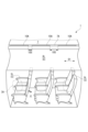
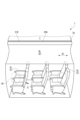
図1~図3は、客室2の内壁3、床4、座席5、荷物収納部6、および天井7を示している。内壁3には窓の開口3Aが形成されている。
(Guest room configuration)
The air conditioning system of the
1-3 show the
本明細書において、航空機の機体の軸線(機軸)に沿った方向のことを機軸方向D1と定義する。この機軸方向D1の機首側を「前」、尾翼側を「後」と称するものとする。
機軸と直交するように右舷と左舷とを結ぶ方向のことを左右方向D2と定義する。上記の前および後を基準として、右舷は、機軸よりも右側を言い、左舷は、機軸よりも左側を言う。さらに、左右方向D2における機体の外側のことを外舷と言い、機体の内側のことを内舷と言うものとする。
本明細書における「上」および「下」は、鉛直方向の上および下に従う。
In this specification, the direction along the axis of the fuselage (machine axis) of the aircraft is defined as the machine axis direction D1. The nose side of this axis direction D1 is called "front", and the tail side is called "rear".
The direction that connects the starboard side and the port side so as to be perpendicular to the axis is defined as a left-right direction D2. Based on the above front and rear, starboard refers to the right side of the axis, and port refers to the left side of the axis. Furthermore, the outer side of the fuselage in the horizontal direction D2 is called the outerboard, and the inner side of the fuselage is called the innerboard.
"Top" and "bottom" as used herein follow the vertical direction up and down.
客室2が配置される機体の胴体8は、図1に示すように、典型的には円形の横断面を呈する。客室2の内壁3および天井7は、胴体8のスキン81の裏側に沿って円弧状に湾曲している。
客室2は、内壁3と天井7と床4との内側に、機軸を中心に左右対称の形状に区画されていることが好ましい。
The
It is preferable that the
座席5は、通路9を挟んで、客室2の右舷と左舷とにそれぞれ配置されている。座席5は、機体重量バランス等の観点から、機軸を中心に左右対称に配置されることが好ましい。本実施形態では、右舷の座席5Rが2列をなし、同じく左舷の座席5Lも2列をなし、それぞれ機軸方向D1に所定の間隔をおいて並んでいる。通路9の位置は、左右方向D2の中心部に相当する。
The
手荷物が収納される荷物収納部6(6R,6L)も、機軸を中心に左右対称に構成されている。右舷の荷物収納部6Rは、座席5Rの上方に位置し、左舷の荷物収納部6Lは、座席5Lの上方に位置している。天井7は、荷物収納部6Rと荷物収納部6Lとの左右方向D2の間に露出している。
荷物収納部6R,6Lの閉じられた扉61と、天井7と、内壁3と、床4とに囲まれた空間2Aに、天井7付近に位置する吹出口10Aから調和空気が吹き出される。
客室空間2Aを流動した調和空気は、例えば床4の付近に位置する排気口から図示しない排気ダクトに流入する。
左右対称の形状である客室空間2Aに、後述するように、左右方向D2にほぼ対称な風速分布が与えられることとなる。
The baggage storage sections 6 (6R, 6L) for storing baggage are also configured symmetrically about the axis. The starboard
Conditioned air is blown out from an
The conditioned air that has flowed through the
A substantially symmetrical wind speed distribution in the left-right direction D2 is given to the
吹出口10Aは、空調ダクト10R,10L(図3)の吹出部11の末端部19に位置している。吹出口10Aは、天井7付近で荷物収納部6R,6Lのそれぞれの上方に位置している。図1および図2に示すように、複数のスリット状の吹出口10Aが、機軸方向D1に、吹出口10Aの長さよりも狭い間隔をおいて配置されている。
The
さて、空調システムにより温度や流量等が制御された調和空気は、機体の右舷および左舷にそれぞれ設けられた空調ダクト10(10R,10L)により各予圧区画に供給される。図3には、空調ダクト10の一部である支流ダクトを示している。
空調ダクト10は、概ね機軸方向D1に沿って床4よりも下方の空間41に配置される主流部(図示しない)と、主流部を流れる調和空気が分配される複数の支流部とを含んでいる。
図3に示す空調ダクト10の支流部は、図示しない主流部から、客室2の内壁3とスキン81との間を上方に延び、さらに荷物収納部6とスキン81との間を上方に延びて吹出部11まで至る。支流部は、スキン81を裏側から支持する図示しないストリンガ等に取り付けられている。
本実施形態では、空調ダクト10の各支流部に、吹出部11が個別に対応している。
Conditioned air, the temperature and flow rate of which are controlled by the air conditioning system, is supplied to each preload section through air conditioning ducts 10 (10R, 10L) provided on the starboard side and port side of the fuselage, respectively. FIG. 3 shows a tributary duct that is part of the
The air-
The tributary portion of the air-
In this embodiment, each branch of the air-
(空調ダクトの末端側の構成)
以下、図3~図5を参照し、空調ダクト10Rと、空調ダクト10Lとを備えた空調ダクト構造100の末端部19およびその近傍について説明する。
空調ダクト10R,10Lのそれぞれにおける末端部19およびその近傍を含む末端区間101を図3に実線で示しているように、末端区間101は、スキン81の裏側にほぼ沿うように、外舷から内舷に向けて延びている。末端区間101は、内壁3とスキン81との間を立ち上がる上流区間102に接続される。
空調ダクト10R,10Lの末端区間101や上流区間102は、典型的には樹脂材料から構成されている。
(Construction of terminal side of air conditioning duct)
The
As shown in solid lines in FIG. 3, the
右舷の空調ダクト10Rの末端区間101は、天井7付近で客室2に調和空気を吹き出す吹出部11と、吹出部11の上流側に連なる吹出上流部12とを含んでいる。
同様に、左舷の空調ダクト10Lの末端区間101は、天井7付近で客室2に調和空気を吹き出す吹出部11と、吹出部11の上流側に連なる吹出上流部12とを含んでいる。
A
Similarly, the
吹出上流部12は、円形、楕円形、長円形等の適宜な形状の横断面を呈するダクトであり、荷物収納部6とスキン81との間に、ストリンガ等の部材と干渉せずに配置可能な長さでほぼ全体が直線状に延びている。
The blow-out
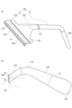
図4および図5(b)に示すように、吹出部11は、天井7よりも外舷から内舷に向けてかつ下方に向けて調和空気を吹き出す。吹出部11は、末端側が水平方向に対して下向きに傾斜するように湾曲箇所110で湾曲している。
吹出部11の末端側は、水平方向に対して下流側へ下向きに傾斜するように湾曲している。図4に示すように、本実施形態の空調ダクト10は、吹出部11の湾曲箇所110を含めて、延出方向の複数の箇所で湾曲している。
As shown in FIGS. 4 and 5(b), the
The end side of the blow-out
右舷の空調ダクト10Rの末端区間101(101R)と、左舷の空調ダクト10Lの末端区間101(101L)とは、同一形状に構成され、図3に示すように、機軸に対して左右対称に配置されている。末端区間101R,101Lは、機軸方向D1においても同じ位置に配置されている。
The terminal section 101 (101R) of the starboard air-
(吹出部の詳細な構成)
図5(a)および(b)を参照し、吹出部11のより詳細な構成を説明する。
吹出部11は、図5(a)に示すように、吹出上流部12に対して流路断面積が拡大されていることが好ましい。また、吹出部11が、吹出上流部12に対して流路断面積が大きい箇所で調和空気の流れを整流する1以上の整流部13を備えていることが好ましい。
(Detailed configuration of blowing part)
A more detailed configuration of the
As for blow-off
本実施形態の吹出部11は、吹出上流部12に対して機軸方向D1に次第に拡がる拡幅部11Aと、拡幅部11Aの下流側に連なり、偏平な断面形状を呈する偏平部11Bとを備えている。吹出部11は、吹出上流部12の軸心に対して機軸方向D1に対称に形成されている。
The
拡幅部11Aは、吹出上流部12に対して上下方向の寸法が若干小さく、吹出上流部12と接続されている位置11Cから機軸方向D1の両側に次第に拡がる形状が与えられている。拡幅部11Aの流路断面積は、吹出上流部12の流路断面積に対して次第に拡大されている。
The widened
偏平部11Bは、拡幅部11Aの最大の幅よりも広い幅を有し、末端側の湾曲箇所110で水平方向に対して下流側へ下方に向けて湾曲している。偏平部11Bの末端部には、吹出口10Aをなす偏平な筒状の出口部材11Dが別体で備えられている。
偏平部11Bは、図4および図5に示すように、荷物収納部6の上方の天井7付近で、天井7に設置された部材7Aに開口している。
より具体的には、右舷の偏平部11Bは、天井7の右端の付近であって右舷の荷物収納部6Rと天井7との境界の近傍に開口し、左舷の偏平部11Bは、天井7の左端の付近であって左舷の荷物収納部6Lと天井7との境界の近傍に開口している。
胴体8のスキン81の内側に施工されている吹出部11の偏平部11Bに、室内側から、部材7Aに形成された開口(図示しない)を介して出口部材11Dを装着すると、部材7Aに吹出部11を固定することができる。
The
As shown in FIGS. 4 and 5, the
More specifically, the starboard
When the
吹出口10Aは、図2に示すように、機軸方向D1と平行な同一直線上に沿って所定の間隔105をおいて配置されている。各吹出口10Aから吹き出される気流の風速分布を機軸方向D1に均一化する観点より、間隔105の寸法を最小化することが好ましい。間隔105は、例えば、機軸方向D1における吹出口10Aの長さの1/2以下の寸法であることが好ましい。
機軸方向D1に沿って吹出口10Aをほぼ隙間なく並べると、より好ましい。
As shown in FIG. 2, the
It is more preferable to arrange the
図4に示すように、本実施形態の吹出部11は、吹出上流部12との接続位置から吹出口10Aまでに亘り、側面視においてなだらかなジグザグ状に湾曲している。
なお、吹出部11の末端側が水平方向に対して下流側へ下向きに傾斜するように、吹出部11または吹出上流部12が湾曲していれば足りる。
スキン81と内壁3や天井7との間の間隙に沿って空調ダクト10R,10Lを配置し、かつ空調ダクト10R,10Lの末端部19を水平方向に対して下向きに傾斜させるため、少なくとも末端区間の101の適宜な位置で空調ダクト10R,10Lを湾曲させている。
As shown in FIG. 4, the
In addition, it is sufficient if the
In order to arrange the air-
本実施形態の吹出部11において、詳細には、拡幅部11Aが吹出上流部12の軸線に対し交差する向きに下流側へ下向きに延びており、拡幅部11Aに対し偏平部11Bが交差する向きに下流側へ上向きに延びている。
複数の湾曲箇所110,111,112を含む吹出部11の末端側は、図5(b)に示すように、水平方向に対し角度θをなして傾斜している。
図3に示すように、右舷の空調ダクト10Rの吹出部11と左舷の空調ダクト10Lの吹出部11とは、水平方向に対してそれぞれ等しい角度θをなす方向に調和空気を客室2に吹き出す。
More specifically, in the
As shown in FIG. 5(b), the end side of the
As shown in FIG. 3 , the
後述するように、吹出部11から吹き出された調和空気の流れが天井7に張り付くことを防ぎつつ、右舷の吹出部11からの噴流と左舷の吹出部11からの噴流とを合流させて通路9の床4に向けて吹き下ろすことができるように、吹出部11の末端側の角度θを適切に定めることが好ましい。
As will be described later, while preventing the flow of conditioned air blown out from the
偏平部11Bの末端部の構成は、本実施形態には限られず、適宜に構成することができる。例えば、偏平部11Bの末端部に出口部材11Dが備えられておらず、偏平部11Bの末端部が吹出口10Aをなしていてもよいし、部材7Aに形成された吹出口10Aに、偏平部11Bの末端部が接続されていてもよい。
The configuration of the end portion of the
偏平部11Bは、拡幅部11Aの終端に対して短い軸方向区間で急激に機軸方向D1に拡大されている。拡幅部11Aおよび偏平部11Bにより、調和空気は機軸方向D1(前後方向)に拡げられて、吹出口10Aから客室2に噴出することとなる。
偏平部11Bの内側には、短い区間で調和空気の流れを機軸方向D1に十分に拡げるため、整流部13(図5(a)および(b))が配置されている。
The
Inside the
整流部13は、偏平部11Bにおいて吹出上流部12に対して流路断面積が大きい箇所で調和空気の流れを整流する。整流部13により、流路断面積の急拡大に伴い生じるダクト内の偏流を抑えることができるので、スリット状の吹出口10Aから噴出される調和空気の流れが均等となる。
The rectifying
整流部13は、偏平部11Bの幅が急激に拡大した箇所11Eの下流に位置している。より具体的には、整流部13は、急拡大の箇所11Eと、湾曲箇所110との間に位置している。湾曲箇所110よりも下流に配置されている整流部13により、湾曲箇所110における偏流の影響を受けずに整流効果を十分に得ることができる。
整流部13は、調和空気を整流することができる適宜な部材、例えばパンチングメタルやメッシュ部材等を用いて構成することができる。本実施形態の整流部13は、パンチングメタルであり、調和空気の流れと直交して配置されている。
The rectifying
The straightening
整流部13は、適宜な方法で偏平部11Bに設けることができる。例えば、吹出部11の射出成形の金型に整流部13を配置して行うインサート成形により、整流部13の配置された吹出部11を得ることができる。あるいは、整流部13が配置される位置の上流側と下流側とに吹出部11を分割して成形し、吹出部11の上流部分および下流部分の間に整流部13を挟むようにして、吹出部11に整流部13を組み付けるようにしてもよい。後者の場合は、ダクトに形成された切欠に整流部13を嵌め込むとよい。
The rectifying
整流部13は、拡幅部11Aに配置されていたり、拡幅部11Aと偏平部11Bとの両方に配置されていたりしてもよい。偏平部11Bにおける湾曲箇所110よりも末端側に整流部13が配置されていてもよい。流路断面積の拡大に伴い調和空気をスムーズに拡げるために、適宜な位置に適宜な数の整流部13を配置することができる。
本実施形態の吹出部11によれば、幅が急拡大し、かつ整流部13を備えていることで、短い軸方向長さで必要な機軸方向D1の幅に調和空気を拡げることができる。吹出部11の軸方向の長さが短く、かつ偏平であることから、吹出部11は、設置される間隙の寸法を考慮した省スペースの要求に適合する。
The straightening
According to the blowing
(空調ダクト構造の作用)
図3を参照し、本実施形態の空調ダクト構造100による作用を説明する。
右舷の空調ダクト10Rの吹出部11(11R)からは、破線の矢印F1で示すように、天井7よりも外舷から内舷に向けてかつ下方に向けて調和空気が吹き出される。
左舷の空調ダクト10Lの吹出部11(11L)からも、破線の矢印F2で示すように、天井7よりも外舷から内舷に向けてかつ下方に向けて調和空気が吹き出される。
各吹出部11R,11Lは等しい角度θで下方に向いており、かつ、各吹出部11R,11Lから吹き出される調和空気のそれぞれの流速はほぼ等しいため、右舷からの噴流(F1)と、左舷からの噴流(F2)とは客室2の左右方向の中心部で衝突、合流して、拡散しつつ、下方へと吹き下ろす(図6(a)参照)。
(Action of air conditioning duct structure)
The action of the air
From the blowout portion 11 (11R) of the
Conditioned air is also blown downward from the
Each of the
各吹出部11R,11Lから調和空気が吹き出される位置は、天井7付近ではあるものの、上述したように各吹出部11R,11Lの末端側が天井7から離れる向きである下向きに構成されているため、噴流(F1,F2)がコアンダ効果により上方の天井7に吸い寄せられて張り付くことを防止することができる。各吹出部11R,11Lから調和空気が、上方の天井7へと引き寄せられずに、下方へ向けて噴出するため、噴流(F1,F2)が座席5の下方まで十分に到達する効果が得られる。
Although the position from which the conditioned air is blown out from each of the
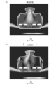
図6(a)および(b)は、客室2のモックアップモデルを用いて調和空気の流れ場を解析した結果に基づいて、客室空間2Aの風速分布を色の濃淡により示している。
図6(a)では、本実施形態の吹出部11および吹出上流部12に相当する条件設定に基づいて、吹出部11と同様の位置から、外舷から内舷に向けて、かつ下方に向けて調和空気が吹き出される。
図6(b)に示す比較例では、吹出部として断面矩形状の吹出口を有するダクトを用いており、吹出部11と同様の位置から、外舷から内舷に向けて、水平方向に調和空気が吹き出される。図6(b)で用いられたダクトの吹出口は、本実施形態の吹出口10Aと比べて上下方向の寸法(高さ)が大きく、機軸方向D1の寸法(幅)は小さい。比較例の吹出口の幅が狭いため、比較例において機軸方向D1に隣り合う吹出口の間隔は、本実施形態の吹出口10Aの間隔と比べて広い。
本実施形態と比較例とのそれぞれの吹出部の開口面積は、ほぼ同等である。比較例のダクトの吹出口は、それよりも上流部に対して流路断面積が拡大されている。
6(a) and 6(b) show the wind speed distribution in the
In FIG. 6A, based on the condition settings corresponding to the
In the comparative example shown in FIG. 6(b), a duct having an outlet with a rectangular cross section is used as the outlet. Air is blown out. The outlet of the duct used in FIG. 6B has a larger dimension (height) in the vertical direction and a smaller dimension (width) in the axial direction D1 than the
The opening areas of the blowout portions of the present embodiment and the comparative example are substantially the same. The air outlet of the duct of the comparative example has a channel cross-sectional area that is larger than that of the upstream portion.
比較例(図6(b))では、右舷および左舷から吹き出された調和空気が天井7に張り付いている。そのため、座席5の下方にまで調和空気が到達しない領域が存在する上、合流位置Cが客室2の左右方向D2の中心からずれており、それに伴い、吹き下ろす流れの風速分布の対称性が損なわれている。図6(b)に示す例では、合流位置Cが図6(b)の左側(右舷)へずれているため、通路の右側の座席5Rでは風速が速く、通路の左側の座席5Lでは風速が遅い傾向にある。風速の違いは温度差に繋がる。
In the comparative example ( FIG. 6( b )), the conditioned air blown out from the starboard side and the port side clings to the
それに対して、吹出部11により下向きに調和空気を吹き出す本実施形態(図6(a))では、右舷および左舷から吹き出された調和空気の流れが天井7から離れている。そして、右舷からの噴流と左舷からの噴流とが合流し、拡散しつつ吹き下ろす領域を含めて、風速分布が左右方向D2にほぼ対称な流れ場が客室空間2Aに与えられる。図6(a)に示す解析結果によれば、通路9の左右両側にほぼ均一な風速分布の流れ場が与えられる。
On the other hand, in the present embodiment (FIG. 6A) in which the conditioned air is blown downward from the blowing
図6(a)および図3に示すように、噴流(F1,F2)が天井7に張り付いていなければ、暖房時の調和空気であっても、調和空気の噴流(F1,F2)を座席5の下方まで到達させることができ、噴流(F1,F2)の僅かな流速差に起因する風力の差により合流位置Cが左右方向D2の中心から右側または左側にずれてしまうことも防止することができる。
As shown in FIGS. 6(a) and 3, if the jets (F1, F2) do not stick to the
本実施形態では、右舷の吹出上流部12と左舷の吹出上流部12とをそれぞれ流れる調和空気に流速差があったとしても、流路断面積が拡大された吹出部11により調和空気の流れが拡げられて下方へ噴出し、合流するまでの間に噴流(F1,F2)の周囲の気流に対する拡散が進む。拡散が進むことで、右舷と左舷との流速の偏りを生じに難くなる結果、右舷の吹出部11により吹き出された調和空気と、左舷の吹出部11により吹き出された調和空気とが所定の合流位置Cで合流する。図6(b)の比較例では、天井7に張り付く流れが拡散を生じ難いため、右舷と左舷との流速の偏りが合流位置Cに影響を与える。
吹出部11が断面円形や断面矩形状等の形態であったとしても、吹出上流部12に対して流路断面積が拡大されているならば、本実施形態と同様である。図6(b)に示す比較例の吹出口の形態であっても、水平方向に調和空気を吹き出すのではなく、本実施形態と同様に下方に向けて調和空気を吹き出すように吹出口の向きが設定されることで、風速分布の非対称性が改善されることとなる。
本実施形態によれば、左右方向D2の中心部である合流位置Cで合流した流れが、客室2の左右方向D2の中心に位置する通路9に向けて吹き下ろすので、座席5に風が吹き付けることを避けることができ、座席5における風速分布、温度分布に偏りが生じることも避けることができる。
In the present embodiment, even if there is a difference in flow velocity between the conditioned air flowing through the
Even if the blow-out
According to this embodiment, the flow that joins at the confluence position C, which is the center in the left-right direction D2, blows down toward the
なお、空調システムによる制御下においてファン等を起因とする流れの揺らぎ等の要因により、合流位置Cが周期的に左右方向D2に変位することは許容される。 It should be noted that, under the control of the air conditioning system, it is permissible for the merging position C to periodically displace in the left-right direction D2 due to factors such as fluctuations in the flow caused by a fan or the like.
さらに、本実施形態によれば、吹出口10Aが狭い間隔で機軸方向D1に沿って配置されているため、客室空間2Aの前後方向(D1)における風速分布の偏りをも避けることができる。そのため、吹出口10Aに近い座席5では温度が低く、吹出口10Aから遠い座席5では温度が高いといったような前後方向(D1)における温度のばらつきを避けることができる。
Furthermore, according to the present embodiment, since the
以上で説明したように、本実施形態によれば、客室2の下方まで調和空気を供給すること、左右方向D2に風速分布の均一化を図ること、および機軸方向D1に風速分布の均一化を図ることのいずれも実現することができる。したがって、客室2全体に亘り風速を規定の範囲内に収めて、乗客の快適性を向上することができる。
As described above, according to the present embodiment, it is possible to supply conditioned air to the lower part of the
風速分布の均一化によって、客室2の全体に亘り温度にムラがなければ、客室2の1箇所または数箇所において検知された代表の温度に基づいて行われる空調システムの制御が、抽気の使用量を抑えながら、調和空気の温度の変動が小さく安定して行われることとなる。つまり、抽気の使用量を抑えて効率よく制御が行われるため、燃費の低減に寄与することができる。
If there is no unevenness in the temperature throughout the
本実施形態によれば、空調ダクト10R,10Lの末端部に位置する吹出部11の向きを水平方向に対して下向きに傾斜させているため、天井7付近から調和空気を吹き出していながら、天井7への噴流(F1,F2)の張り付きを防ぐことができる。
そのため、調和空気を天井7付近まで導く従来の空調ダクトの支流ダクトを使用し、その支流ダクトの末端側に下向きの吹出部11を与えればよいので経済的である。吹出部11に整流部材等の部材を付加する必要がない点でも経済的であって、機体重量の増加を避けながら風速分布の均一化を図ることができる。
以上からすれば、本発明の吹出部11および吹出上流部12を備えた空調ダクト構造100は、新造される航空機1のみならず、既存の航空機1の改修時にも適合する。つまり、既存機の客室2等の予圧区画に調和空気を供給する空調ダクトの末端部に代えて、吹出部11を与えることで、天井7への調和空気の張り付きを防いで、予圧区画の風速分布および温度分布を均一化することができる。
According to this embodiment, since the direction of the blow-out
Therefore, it is economical to use a branch duct of a conventional air conditioning duct that guides the conditioned air to the vicinity of the
In view of the above, the air
さらに、吹出部11の末端側が水平方向に対して下流側へ下向きに傾斜するように吹出部11または吹出上流部12が湾曲しているため、スキン81と内壁3や荷物収納部6等との間の狭隘な間隙にも空調ダクト10R,10Lを取り回し、それぞれの吹出部11を下向きに配置することができる。
Furthermore, since the
(本発明の変形例)
図7、図8(a)および(b)を参照し、客室2の機軸方向D1における風速分布の均一化に関する変形例を説明する。
図7に示すように機軸方向D1に連続した吹出口20Aを有する吹出部21は、図8(a)および(b)に示すように、機軸方向D1に細長いチャンバである。吹出部21は、天井7付近まで調和空気を導く複数の吹出上流部22から調和空気を受け入れ、スリット状の吹出口20Aから客室空間2Aに吹き出す。
(Modification of the present invention)
7, 8(a) and 8(b), description will be given of a modified example of equalization of the wind speed distribution in the axial direction D1 of the
As shown in FIG. 7, the
吹出部21は、吹出部11(図3)と同様に、空調ダクト10R,10Lのそれぞれの末端部として、右舷と左舷とにそれぞれ設けられている。図8(a)に左舷の吹出部21を示すように、各吹出部21は、天井7付近で荷物収納部6R,6Lのそれぞれの上方に位置している。
As with the blowout portion 11 (FIG. 3), the
吹出部21は、機軸方向D1に並んだ複数の吹出上流部22に対応する長さに形成されている。吹出部21の下流側の壁211には、機軸方向D1に並んだ複数の吹出上流部22が接続されている。
図8(a)に示すように、吹出上流部22が湾曲していることにより、吹出部21の末端側が水平方向に対して下向きに傾斜している。そのため、吹出部21は、天井7よりも外舷から内舷に向けてかつ下方に向けて客室2に調和空気を吹き出す。
The
As shown in FIG. 8( a ), due to the curved
図8(b)に示すように2以上の吹出部21を機軸方向D1に接触した状態に、隙間なく隣接して配置することができる。この場合、隣接する複数の吹出部21に亘り、吹出口20Aをなす単一の出口部材21D(図7)を与えることができる。そうすると、部品点数が減り、かつ外観を向上させることができる。
As shown in FIG. 8(b), two or
吹出部21は、客室2の機軸方向D1の全体に亘る長さに形成されていてもよい。その場合は、単一の吹出部21に、客室2の領域において機軸方向D1に並んだ複数の吹出上流部22の全数を接続することができる。
The blow-out
吹出部21によれば、天井7から離れた向きに、調和空気が機軸方向D1において均一に噴出されるため、上記実施形態と同様に天井7への調和空気の張り付きを防いで上下方向や左右方向D2の風速のムラを抑えることに加えて、風速分布を機軸方向D1により一層均一化することができる。
According to the blowing
なお、上記実施形態の吹出部11(図5(a))を機軸方向D1に接触した状態に隣接して配置することによっても、上記変形例と同様の構成を得て、機軸方向D1における風速分布の均一化をより十分に図ることができる。 By arranging the blowout part 11 (FIG. 5(a)) of the above embodiment adjacently in contact with the axis direction D1, a configuration similar to that of the above modification can be obtained, and the wind speed in the axis direction D1 can be reduced. Uniform distribution can be achieved more sufficiently.
上記以外にも、本発明の主旨を逸脱しない限り、上記実施形態で挙げた構成を取捨選択したり、他の構成に適宜変更したりすることが可能である。 In addition to the above, it is possible to select the configurations described in the above embodiments or to change them to other configurations as appropriate without departing from the gist of the present invention.
本発明の空調ダクト10R,10Lの吹出部11は、急激に幅が拡大する箇所を含まずに上流端から下流端に亘り幅が拡大されていてもよい。
本発明の空調ダクト10R,10Lの吹出部11は、天井7よりも外舷から内舷に向けてかつ下方に向けて客室2に調和空気を吹き出す限りにおいて、必ずしも上流に対して流路断面積が拡大している必要はない。上流に対して流路断面積が拡大されていなくても、右舷および左舷の吹出部により吹き出された調和空気の噴流の天井7への張り付きが抑制される。この場合に、噴流の合流位置Cが客室2の左右方向D2の中心(機軸の位置)から若干ずれたとしても許容される。調和空気の噴流の天井7への張り付きが抑制されることにより、座席5の下方まで調和空気を供給することができるので、上下方向の温度差を小さくすることができる。
The blow-out
As long as the
客室2の座席5の配置形態によって、通路9の位置や荷物収納部6の位置も変わり、天井7の形態も変わる。例えば、座席5が配置される領域が、右、中間、左の3つあり、それらの隣接する領域の間に2つの通路9が存在し、各領域の頭上に合計3つの荷物収納部が存在する場合を考える。その場合には、天井7が、左の荷物収納部と中間の荷物収納部との間、および中間の荷物収納部と右の荷物収納部との間の2箇所に露出する。この場合において、左側の天井露出部の付近に本発明の空調ダクトの吹出部11を左右対称に与え、右側の天井露出部の付近にも本発明の空調ダクトの吹出部11を左右対称に与えることにより、調和空気の天井への張り付きを防いで客室内の風速分布、温度分布の均一化を図ることができる。
Depending on the layout of the
本発明の空調ダクト構造100は、客室2に限らず、操縦室等の他の与圧区画にも適用することができる。
The air
1 航空機
2 客室(与圧区画)
2A 客室空間
3 内壁
4 床
5,5L,5R 座席
6,6L,6R 荷物収納部
7 天井
7A 部材
8 胴体
9 通路
100 空調ダクト構造
10,10L,10R 空調ダクト
10A 吹出口
11,11L,11R 吹出部
11A 拡幅部
11B 偏平部
11C 接続位置
11D 出口部材
12 吹出上流部
13 整流部
19 末端部
20A 吹出口
21 吹出部
21D 出口部材
22 吹出上流部
61 扉
81 スキン
101,101L,101R 末端区間
102 上流区間
105 間隔
110,111,112 湾曲箇所
211 壁
C 合流位置
D1 機軸方向
D2 左右方向
1
Claims (16)
右舷および左舷のそれぞれの前記空調ダクトは、
前記天井よりも外舷から内舷に向けてかつ下方に向けて前記与圧区画に前記調和空気を吹き出す吹出部と、前記吹出部の上流側に連なる吹出上流部と、を含み、
かつ、前記吹出部の末端側が水平方向に対して下向きに傾斜するように前記吹出部または前記吹出上流部が湾曲しており、
右舷側の前記吹出部からの前記調和空気の噴流と、左舷側の前記吹出部からの前記調和空気の噴流とは、水平方向に対して等しい角度で下方に向けられ、実質的に等しい速度で噴出し、
前記右舷側の前記吹出部からの前記噴流と、前記左舷側の前記吹出部からの前記噴流とは、前記右舷側の前記吹出部と前記左舷側の前記吹出部の間の中心部で合流し、拡散しつつ下方に吹き下ろすことを特徴とする航空機の空調ダクト構造。
Air conditioning ducts provided on the starboard side and the port side of the pressurized compartment of the aircraft, respectively, for guiding conditioned air to the vicinity of the ceiling of the pressurized compartment of the aircraft,
The air conditioning ducts on each of the starboard and port sides are
A blowout section that blows the conditioned air from the outer side to the inner side and downward from the ceiling to the pressurized section, and a blowout upstream section that continues upstream of the blowout section,
and the blowout portion or the blowout upstream portion is curved such that a distal end side of the blowout portion is inclined downward with respect to the horizontal direction,
The jet of conditioned air from the outlet on the starboard side and the jet of conditioned air from the outlet on the port side are directed downward at equal angles to the horizontal and at substantially equal velocities. erupt,
The jet from the starboard-side blow-out portion and the jet from the port-side blow-out portion join at a central portion between the starboard-side blow-out portion and the port-side blow-out portion. , an air-conditioning duct structure for an aircraft characterized by blowing downward while diffusing .
右舷の前記吹出部は、右舷の前記荷物収納部の上方に開口し、
左舷の前記吹出部は、左舷の前記荷物収納部の上方に開口している、
請求項1に記載の航空機の空調ダクト構造。
The ceiling is exposed between the left and right direction between the starboard luggage storage section and the port side luggage storage section located above the seats of the cabin as the pressurized compartment,
The starboard blowout portion opens above the starboard baggage storage portion,
The blowout section on the port side opens above the baggage storage section on the port side,
The aircraft air conditioning duct structure according to claim 1.
左舷の前記吹出部は、前記天井の左端の付近であって左舷の前記荷物収納部と前記天井との境界の近傍に開口している、
請求項2に記載の航空機の空調ダクト構造。
The starboard blowout portion opens near the right end of the ceiling and near the boundary between the starboard cargo storage portion and the ceiling,
The port-side air outlet is near the left end of the ceiling and is open near the boundary between the port-side cargo storage unit and the ceiling,
The aircraft air conditioning duct structure according to claim 2.
前記客室の内壁とスキンとの間、および前記荷物収納部と前記スキンとの間を延びて前記吹出部まで至る、
請求項2または3に記載の航空機の空調ダクト構造。
The air conditioning duct is
extending between the inner wall of the passenger compartment and the skin and between the luggage compartment and the skin to the outlet;
The aircraft air conditioning duct structure according to claim 2 or 3.
左右対称の形態に構成され、水平方向に対してそれぞれ等しい角度をなす方向に前記調和空気を吹き出す、
請求項1から4のいずれか一項に記載の航空機の空調ダクト構造。
The blowout section on the starboard side and the blowout section on the port side are
The conditioned air is configured in a symmetrical form and blows the conditioned air in directions that form equal angles with respect to the horizontal direction.
The aircraft air conditioning duct structure according to any one of claims 1 to 4.
請求項5に記載の航空機の空調ダクト構造。
The position of the aisle between the starboard seat and the port seat in the pressurized compartment corresponds to the center of the pressurized compartment in the horizontal direction,
The aircraft air conditioning duct structure according to claim 5.
請求項1から6のいずれか一項に記載の航空機の空調ダクト構造。
The blow-out portion has a channel cross-sectional area enlarged with respect to the blow-out upstream portion,
The aircraft air conditioning duct structure according to any one of claims 1 to 6.
前記吹出上流部に対して、前記航空機の機軸方向に流路断面積が拡大されている、
請求項7に記載の航空機の空調ダクト構造。
The blowing part is
A flow passage cross-sectional area is enlarged in the axial direction of the aircraft with respect to the blowout upstream portion,
The aircraft air conditioning duct structure according to claim 7.
請求項7または8に記載の航空機の空調ダクト構造。
The blowout section includes a straightening section that straightens the flow of the conditioned air at a location where the flow passage cross-sectional area is larger than that of the blowout upstream section.
The aircraft air conditioning duct structure according to claim 7 or 8.
請求項9に記載の航空機の空調ダクト構造。
The rectifying section is configured using a punching metal,
The aircraft air conditioning duct structure according to claim 9.
前記吹出上流部に対して前記航空機の機軸方向に次第に拡がる拡幅部と、
前記拡幅部の下流側に連なり、偏平な断面形状を呈する偏平部と、を備える、
請求項8から10のいずれか一項に記載の航空機の空調ダクト構造。
The blowing part is
a widened portion that gradually widens in the axial direction of the aircraft with respect to the blowout upstream portion;
a flat portion having a flat cross-sectional shape, which is connected to the downstream side of the widened portion;
Aircraft air conditioning duct structure according to any one of claims 8 to 10.
前記整流部は、前記偏平部に備えられる、
請求項11に記載の航空機の空調ダクト構造。
The blowout section includes a straightening section that straightens the flow of the conditioned air at a location where the cross-sectional area of the flow path is larger than that of the blowout upstream section,
The rectifying section is provided in the flat section,
The aircraft air conditioning duct structure according to claim 11.
複数の前記空調ダクトにそれぞれ対応する前記吹出部が、
前記機軸方向と平行な同一直線上に沿って、前記機軸方向における前記吹出部の長さの1/2以下の間隔をおいて配置されている、
請求項8から12のいずれか一項に記載の航空機の空調ダクト構造。
The blowout portion extends in the axial direction of the aircraft with respect to the blowout upstream portion,
The blow-out portions respectively corresponding to the plurality of air-conditioning ducts,
are arranged along the same straight line parallel to the axial direction at intervals of 1/2 or less of the length of the blowout portion in the axial direction,
Aircraft air conditioning duct structure according to any one of claims 8 to 12.
前記航空機の機軸方向に沿って連続し、
前記天井付近まで前記調和空気を導く複数の前記吹出上流部から前記調和空気を受け入れて吹き出す、
請求項1から13のいずれか一項に記載の航空機の空調ダクト構造。
The blowing part is
Continuous along the axial direction of the aircraft,
receiving and blowing out the conditioned air from the plurality of blowing upstream parts that guide the conditioned air to the vicinity of the ceiling;
Aircraft air conditioning duct structure according to any one of claims 1 to 13.
前記与圧区画と、を備える、
ことを特徴とする航空機。
an air conditioning duct structure according to any one of claims 1 to 14;
the pressurized compartment;
An aircraft characterized by:
航空機の右舷および左舷にそれぞれ設けられ、前記航空機の与圧区画の天井付近まで調和空気を導く空調ダクトに、前記天井よりも外舷から内舷に向けてかつ下方に向けて前記与圧区画に前記調和空気を吹き出す吹出部を与えるステップを含み、
右舷側の前記吹出部からの前記調和空気の噴流と、左舷側の前記吹出部からの前記調和空気の噴流とは、水平方向に対して等しい角度で下方に向けられ、実質的に等しい速度で噴出し、
前記右舷側の前記吹出部からの前記噴流と、前記左舷側の前記吹出部からの前記噴流とは、前記右舷側の前記吹出部と前記左舷側の前記吹出部の間の中心部で合流し、拡散しつつ下方に吹き下ろすことを特徴とする航空機の製造方法。 A method of manufacturing an aircraft, comprising:
Air-conditioning ducts provided on the starboard side and port side of the aircraft, respectively, that guide conditioned air to the vicinity of the ceiling of the pressurized compartment of the aircraft. including the step of providing a blowing unit for blowing the conditioned air;
The jet of conditioned air from the outlet on the starboard side and the jet of conditioned air from the outlet on the port side are directed downward at equal angles to the horizontal and at substantially equal velocities. erupt,
The jet from the starboard-side blow-out portion and the jet from the port-side blow-out portion join at a central portion between the starboard-side blow-out portion and the port-side blow-out portion. , a method of manufacturing an aircraft characterized by blowing downward while diffusing .
Priority Applications (2)
| Application Number | Priority Date | Filing Date | Title |
|---|---|---|---|
| JP2019006461A JP7281908B2 (en) | 2019-01-18 | 2019-01-18 | Aircraft air conditioning duct structure, aircraft, and aircraft manufacturing method |
| US16/718,882 US11548647B2 (en) | 2019-01-18 | 2019-12-18 | Air-conditioning duct structure of aircraft, aircraft, and method of manufacturing aircraft |
Applications Claiming Priority (1)
| Application Number | Priority Date | Filing Date | Title |
|---|---|---|---|
| JP2019006461A JP7281908B2 (en) | 2019-01-18 | 2019-01-18 | Aircraft air conditioning duct structure, aircraft, and aircraft manufacturing method |
Publications (2)
| Publication Number | Publication Date |
|---|---|
| JP2020114716A JP2020114716A (en) | 2020-07-30 |
| JP7281908B2 true JP7281908B2 (en) | 2023-05-26 |
Family
ID=71609648
Family Applications (1)
| Application Number | Title | Priority Date | Filing Date |
|---|---|---|---|
| JP2019006461A Active JP7281908B2 (en) | 2019-01-18 | 2019-01-18 | Aircraft air conditioning duct structure, aircraft, and aircraft manufacturing method |
Country Status (2)
| Country | Link |
|---|---|
| US (1) | US11548647B2 (en) |
| JP (1) | JP7281908B2 (en) |
Families Citing this family (2)
| Publication number | Priority date | Publication date | Assignee | Title |
|---|---|---|---|---|
| US20210387737A1 (en) * | 2020-06-10 | 2021-12-16 | Walter Dorwin Teague Associates, Inc. | Passenger air shield |
| JP7830037B2 (en) * | 2020-07-23 | 2026-03-16 | ザ・ボーイング・カンパニー | Air supply system for use in aircraft |
Citations (2)
| Publication number | Priority date | Publication date | Assignee | Title |
|---|---|---|---|---|
| US20070164158A1 (en) | 2005-12-21 | 2007-07-19 | Airbus Deutschland Gmbh | Aircraft Fuselage With Upper And Lower Deck |
| JP2016155537A (en) | 2014-07-21 | 2016-09-01 | ザ・ボーイング・カンパニーThe Boeing Company | Aeration system, method and apparatus |
Family Cites Families (11)
| Publication number | Priority date | Publication date | Assignee | Title |
|---|---|---|---|---|
| JPH01178536U (en) | 1988-06-03 | 1989-12-21 | ||
| DE19509773C1 (en) * | 1995-03-17 | 1996-06-27 | Daimler Benz Aerospace Airbus | Ventilating system for reducing concentration of impurities in aircraft passenger area |
| US5897079A (en) * | 1997-08-18 | 1999-04-27 | Mcdonnell Douglas Corporation | Air curtain insulating system for aircraft cabin |
| US6812982B2 (en) * | 2000-05-12 | 2004-11-02 | Fuji Photo Film Co., Ltd. | Optical compensatory sheet producing method and apparatus, thermal treating method and apparatus, and dust removing method and apparatus |
| JP3383798B2 (en) | 2001-01-29 | 2003-03-04 | 川崎重工業株式会社 | Air flow blowing device |
| DE102006005543B4 (en) | 2006-02-07 | 2010-06-24 | Airbus Deutschland Gmbh | Aircraft air conditioning system with cyclone vents |
| DE102007049926A1 (en) * | 2007-10-18 | 2009-04-23 | Airbus Deutschland Gmbh | System and method for air conditioning at least a portion of an aircraft |
| DE102008026093B4 (en) * | 2008-05-30 | 2014-02-13 | Airbus Operations Gmbh | System and method for ventilating an aircraft cabin |
| DE102012009632A1 (en) * | 2012-05-14 | 2013-11-14 | Airbus Operations Gmbh | Modular overhead luggage rack |
| JP6121161B2 (en) * | 2012-12-27 | 2017-04-26 | 川崎重工業株式会社 | Vehicle air conditioning system and railway vehicle equipped with the same |
| US9581163B2 (en) * | 2013-08-27 | 2017-02-28 | The Boeing Company | Air diffuser systems, methods, and apparatuses |
-
2019
- 2019-01-18 JP JP2019006461A patent/JP7281908B2/en active Active
- 2019-12-18 US US16/718,882 patent/US11548647B2/en active Active
Patent Citations (2)
| Publication number | Priority date | Publication date | Assignee | Title |
|---|---|---|---|---|
| US20070164158A1 (en) | 2005-12-21 | 2007-07-19 | Airbus Deutschland Gmbh | Aircraft Fuselage With Upper And Lower Deck |
| JP2016155537A (en) | 2014-07-21 | 2016-09-01 | ザ・ボーイング・カンパニーThe Boeing Company | Aeration system, method and apparatus |
Also Published As
| Publication number | Publication date |
|---|---|
| JP2020114716A (en) | 2020-07-30 |
| US20200231287A1 (en) | 2020-07-23 |
| US11548647B2 (en) | 2023-01-10 |
Similar Documents
| Publication | Publication Date | Title |
|---|---|---|
| US9561855B2 (en) | Alternate directional momentum ventilation nozzle for passenger cabins | |
| KR102190027B1 (en) | Thermal system with high aspect ratio vents | |
| EP2851298B1 (en) | Air diffuser system | |
| EP0292033B1 (en) | Dual nozzle cabin ventilation system | |
| US10743671B2 (en) | Air conditioning seat | |
| CN106240287B (en) | Personal air flow device for a vehicle | |
| US6413159B1 (en) | Airplane cabin overhead air outlets | |
| EP3728036B1 (en) | Overhead flow distribution assembly for aircraft cabin | |
| US10315775B2 (en) | Duct structure which discharges air through air pressure regulating valve and aircraft | |
| JP7281908B2 (en) | Aircraft air conditioning duct structure, aircraft, and aircraft manufacturing method | |
| RU2616490C2 (en) | Vehicle air conditioning system and railway vehicle equipped with such system | |
| EP3967603B1 (en) | Air distribution nozzles, aircraft that include air distribution nozzles, and methods of utilizing air distribution nozzles | |
| JP6428004B2 (en) | Blower | |
| US11034215B2 (en) | Vehicle ventilation system | |
| US9011216B1 (en) | Diversion directional nozzle | |
| EP3943394B1 (en) | Air distribution system for use in an aircraft | |
| JP6358028B2 (en) | Vehicle air conditioner | |
| JP7600975B2 (en) | Vehicle air conditioning system | |
| JP7600974B2 (en) | Vehicle air conditioning system | |
| JP5474028B2 (en) | Air conditioning equipment and vehicles | |
| CZ307411B6 (en) | A ventilation diffuser for vehicles and a vehicle with a ventilation diffuser | |
| JP7480471B2 (en) | Vehicle Circulator | |
| EP4082909B1 (en) | Air distribution nozzles, aircraft that include air distribution nozzles, and methods of utilizing air distribution nozzles | |
| CN113557149A (en) | vehicle ventilation components | |
| JP4048107B2 (en) | Railway vehicle |
Legal Events
| Date | Code | Title | Description |
|---|---|---|---|
| A625 | Written request for application examination (by other person) |
Free format text: JAPANESE INTERMEDIATE CODE: A625 Effective date: 20220107 |
|
| A131 | Notification of reasons for refusal |
Free format text: JAPANESE INTERMEDIATE CODE: A131 Effective date: 20221122 |
|
| A977 | Report on retrieval |
Free format text: JAPANESE INTERMEDIATE CODE: A971007 Effective date: 20221125 |
|
| A521 | Request for written amendment filed |
Free format text: JAPANESE INTERMEDIATE CODE: A523 Effective date: 20230119 |
|
| TRDD | Decision of grant or rejection written | ||
| A01 | Written decision to grant a patent or to grant a registration (utility model) |
Free format text: JAPANESE INTERMEDIATE CODE: A01 Effective date: 20230509 |
|
| A61 | First payment of annual fees (during grant procedure) |
Free format text: JAPANESE INTERMEDIATE CODE: A61 Effective date: 20230516 |
|
| R150 | Certificate of patent or registration of utility model |
Ref document number: 7281908 Country of ref document: JP Free format text: JAPANESE INTERMEDIATE CODE: R150 |