EP3943370A1 - Spoiler of a vehicle - Google Patents
Spoiler of a vehicle Download PDFInfo
- Publication number
- EP3943370A1 EP3943370A1 EP20187461.7A EP20187461A EP3943370A1 EP 3943370 A1 EP3943370 A1 EP 3943370A1 EP 20187461 A EP20187461 A EP 20187461A EP 3943370 A1 EP3943370 A1 EP 3943370A1
- Authority
- EP
- European Patent Office
- Prior art keywords
- spoiler
- heat sink
- cavity
- cooling channel
- channel structure
- Prior art date
- Legal status (The legal status is an assumption and is not a legal conclusion. Google has not performed a legal analysis and makes no representation as to the accuracy of the status listed.)
- Granted
Links
Images



Classifications
-
- B—PERFORMING OPERATIONS; TRANSPORTING
- B62—LAND VEHICLES FOR TRAVELLING OTHERWISE THAN ON RAILS
- B62D—MOTOR VEHICLES; TRAILERS
- B62D35/00—Vehicle bodies characterised by streamlining
- B62D35/007—Rear spoilers
-
- H—ELECTRICITY
- H01—ELECTRIC ELEMENTS
- H01Q—ANTENNAS, i.e. RADIO AERIALS
- H01Q1/00—Details of, or arrangements associated with, antennas
- H01Q1/02—Arrangements for de-icing; Arrangements for drying-out ; Arrangements for cooling; Arrangements for preventing corrosion
-
- H—ELECTRICITY
- H01—ELECTRIC ELEMENTS
- H01Q—ANTENNAS, i.e. RADIO AERIALS
- H01Q1/00—Details of, or arrangements associated with, antennas
- H01Q1/27—Adaptation for use in or on movable bodies
- H01Q1/32—Adaptation for use in or on road or rail vehicles
- H01Q1/325—Adaptation for use in or on road or rail vehicles characterised by the location of the antenna on the vehicle
- H01Q1/3275—Adaptation for use in or on road or rail vehicles characterised by the location of the antenna on the vehicle mounted on a horizontal surface of the vehicle, e.g. on roof, hood, trunk
-
- H—ELECTRICITY
- H01—ELECTRIC ELEMENTS
- H01Q—ANTENNAS, i.e. RADIO AERIALS
- H01Q1/00—Details of, or arrangements associated with, antennas
- H01Q1/27—Adaptation for use in or on movable bodies
- H01Q1/32—Adaptation for use in or on road or rail vehicles
- H01Q1/325—Adaptation for use in or on road or rail vehicles characterised by the location of the antenna on the vehicle
- H01Q1/3291—Adaptation for use in or on road or rail vehicles characterised by the location of the antenna on the vehicle mounted in or on other locations inside the vehicle or vehicle body
-
- H—ELECTRICITY
- H01—ELECTRIC ELEMENTS
- H01Q—ANTENNAS, i.e. RADIO AERIALS
- H01Q1/00—Details of, or arrangements associated with, antennas
- H01Q1/42—Housings not intimately mechanically associated with radiating elements, e.g. radome
-
- H—ELECTRICITY
- H01—ELECTRIC ELEMENTS
- H01Q—ANTENNAS, i.e. RADIO AERIALS
- H01Q1/00—Details of, or arrangements associated with, antennas
- H01Q1/44—Details of, or arrangements associated with, antennas using equipment having another main function to serve additionally as an antenna, e.g. means for giving an antenna an aesthetic aspect
-
- H—ELECTRICITY
- H01—ELECTRIC ELEMENTS
- H01Q—ANTENNAS, i.e. RADIO AERIALS
- H01Q23/00—Antennas with active circuits or circuit elements integrated within them or attached to them
-
- H—ELECTRICITY
- H05—ELECTRIC TECHNIQUES NOT OTHERWISE PROVIDED FOR
- H05K—PRINTED CIRCUITS; CASINGS OR CONSTRUCTIONAL DETAILS OF ELECTRIC APPARATUS; MANUFACTURE OF ASSEMBLAGES OF ELECTRICAL COMPONENTS
- H05K7/00—Constructional details common to different types of electric apparatus
- H05K7/20—Modifications to facilitate cooling, ventilating, or heating
-
- Y—GENERAL TAGGING OF NEW TECHNOLOGICAL DEVELOPMENTS; GENERAL TAGGING OF CROSS-SECTIONAL TECHNOLOGIES SPANNING OVER SEVERAL SECTIONS OF THE IPC; TECHNICAL SUBJECTS COVERED BY FORMER USPC CROSS-REFERENCE ART COLLECTIONS [XRACs] AND DIGESTS
- Y02—TECHNOLOGIES OR APPLICATIONS FOR MITIGATION OR ADAPTATION AGAINST CLIMATE CHANGE
- Y02T—CLIMATE CHANGE MITIGATION TECHNOLOGIES RELATED TO TRANSPORTATION
- Y02T10/00—Road transport of goods or passengers
- Y02T10/80—Technologies aiming to reduce greenhouse gasses emissions common to all road transportation technologies
- Y02T10/82—Elements for improving aerodynamics
Definitions
- the present disclosure relates to a spoiler of a vehicle.
- the invention provides a spoiler of a vehicle comprising a body and an electronic component, wherein the body comprises a cavity, wherein the electronic component is arranged in this cavity, wherein the spoiler comprises an outer recess, wherein the spoiler comprises an outer heat sink, wherein the outer heat sink is arranged in the outer recess of the body and wherein the outer recess passes over into the cavity.
- a spoiler is appropriate to enhance the thermal management of a telematics system since the electronic component which is part of the spoiler can be cooled efficiently.
- the body of the spoiler comprises an inner recess and the spoiler comprises an inner heat sink, wherein the inner heat sink is arranged in the inner recess of the body and the inner recess passes over into the cavity and wherein the cavity is arranged between the outer recess and the inner recess.
- the second heat sink enhance the cooling capacity of the spoiler.
- the outer heat sink forms a part of a skin of the body or the outer heat sink is covered by a skin of the body. Such a positioning of the outer heatsink provides an efficient cooling since the heat sink can be cooled directly or nearly directly by the air stream.
- the body comprises a cooling channel structure, wherein the inner recess is arranged between the cavity and a middle section of the cooling channel structure and wherein the cooling channel structure comprises at least one inlet and at least one outlet.
- the cooling capacity is enhanced by a cooling channel structure. This means that cooling is more effective.
- the inlet and the outlet are positioned in such a way on the spoiler that an airflow is generated in the cooling channel structure by the airstream, wherein the inlet is located in a frontside area of the body of the spoiler in which overpressure is generated by the airstream and wherein the outlet is located in a backside area of the body of the spoiler in which the pressure is lower than the overpressure.
- the inlet and the outlet are positioned in such a way on the spoiler that an airflow is generated in the cooling channel structure by the airstream, wherein the outlet is located in a frontside area of the body of the spoiler in which suction is generated by the airstream and the inlet is located in a backside area of the body of the spoiler in which air can be sucked in.
- Such an arrangement generates a highly effective cooling.
- the spoiler comprises a fan, wherein the fan is arranged either in the cooling channel structure or outside the body at the outlet or at the inlet of the cooling channel structure, whereby in the case that the fan is located outside the body of the spoiler the fan comprises a housing which is shaped aerodynamically and complements the body.
- the electronic component comprises
- the least one amplifier is arranged in the cavity either near to the TCU and near to the inner heat sink or near to the antennas and near to the outer heat sink.
- a first cooling channel structure is positioned in such a way that the TCU is cooled and at least one additional cooling channel structure is positioned in such a way that at least one antenna and/or at least one amplifier is cooled.
- Such an arrangement with multiple cooling channel structures makes the cooling more effective and allows to dimension each cooling channel structure with respect to the necessary cooling capacity.
- a TCU is an embedded system on board of a vehicle that provides radio communication capabilities to the vehicle to. e.g., access the Internet.
- an electronic component comprises at least one electronic unit and for example as a first electronic unit a TCU and as a second electronic unit antennas and optionally as a third electronic unit amplifiers.
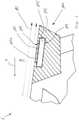
- Figure 1 shows a spoiler 1 of a vehicle V, which is mounted to the roof R of the vehicle V and is representative for the spoilers shown in figures 2 to 5 .
- Figure 2 shows in a cutting view schematically a first embodiment of an inventive spoiler 101 of a vehicle V, wherein the spoiler 101 is designed generally similar to the spoiler 1 shown in figure 1 .
- the Spoiler 101 comprises a body 102 and an electronic component 103.
- the body 102 comprises a cavity 104, wherein the electronic component 103 is arranged in this cavity 104.
- the spoiler 101 comprises an outer recess 105 and that the spoiler comprises an outer heat sink 106, wherein the outer heat sink 106 is arranged in the outer recess 105 of the body 102 and wherein the outer recess 105 passes over into the cavity 104.
- the electronic component 103 is cooled by the heat sink 106 which is in contact with a bottom side of a skin 102a of the body 102 of the spoiler 101. Heat that is generated by the electronic component 103 is conveyed via the outer heat sink 106 through the skin 102a of the body 102 to a top side of the skin 102a and from the top side of the skin 102a to the ambient air A, wherein the cooling effect is enlarged when the vehicle V moves and an airstream AS cools the skin 102a of the body 102 in an area of the heat sink 106.
- the heat sink forms a part of a skin of the body of the spoiler and the heat is directly transferred from the heat sink to the ambient air.
- Figure 3 shows in a cutting view schematically a second embodiment of an inventive spoiler 201 of a vehicle V.
- the Spoiler 201 comprises a body 202 and an electronic component 203.
- the body 202 comprises a cavity 204, wherein the electronic component 203 is arranged in this cavity 204.
- the spoiler 201 comprises an outer recess 205 and the spoiler comprises an outer heat sink 206, wherein the outer heat sink 206 is arranged in the outer recess 205 of the body 202 and wherein the outer recess 205 passes over into the cavity 204.
- the spoiler 201 comprises an inner recess 221 and the spoiler 201 comprises an inner heat sink 222, wherein the inner heat sink 222 is arranged in the inner recess 221 of the body 202 and the inner recess 221 passes over into the cavity 204 and wherein the cavity 204 is arranged between the outer recess 205 and the inner recess 221.
- the electronic component 203 is cooled by the heat sink 206 which is in contact with a skin 202a of the body 202 of the spoiler 201. Heat that is generated by the electronic component 203 is conveyed through the skin 202a to ambient air A, wherein the cooling effect is enlarged when the vehicle V moves and an airstream AS cools the skin 202a of the body 202 in an area of the heat sink 206.
- the heat sink forms the surface of the body and the heat is directly transferred to the ambient air.
- the heat sink forms a part of the surface of the body of the spoiler.
- the body 202 comprises a cooling channel structure 241, wherein the inner recess 221 is arranged between the cavity 204 and a middle section 242 of the cooling channel structure 241 and wherein the cooling channel structure 241 comprises an inlet 243 and an outlet 244.
- the inner heat sink 222 is cooled by ambient air A flowing through the cooling channel structure 241.
- the inlet 243 and the outlet 244 are positioned in such a way on the body 202 of the spoiler 201 that an airflow AF is generated in the cooling channel structure 241 by the airstream AS, wherein the inlet 243 is located in a frontside area 245 of the body 202 of the spoiler 201 in which overpressure PI is generated by the airstream AS.
- the outlet is located opposite to the inlet 243 in a backside area 246 of the body 202 of the spoiler 201.
- the airstream AS and the airflow AF run in much in the same direction, namely in the direction of the airstream AS.
- the electronic component 203 comprises antennas 251 and a TCU 252, wherein antennas 251 are housed in the cavity 204 adjacent to the outer heat sink 206 and the TCU 252 is housed in the cavity 204 adjacent to the inner heat sink 222.
- the spoiler 201 may comprise an electric fan 261 (shown in dotted lines), wherein the fan 261 is arranged in the cooling channel structure 241 between the inlet 243 and the middle section 242 of the cooling channel structure 241 and shown by dotted lines.
- the fan will be active, when the vehicle V is stationary and the electronic component 203 is active.
- the fan 261 may be additionally controlled by a temperature sensor.
- the spoiler 201 may comprise an electric fan 262 (shown in dotted lines), wherein the fan 262 is arranged outside the body 202 at the outlet 244 of the cooling channel structure 241.
- the fan 262 comprises a housing 263 which is shaped aerodynamically and complements the body 202 of the spoiler 201.
- the fan 262 will be active, when the vehicle V is stationary and the electronic component 203 is active.
- the fan 262 may be additionally controlled by a temperature sensor.
- Figure 4 shows in a cutting view schematically a third embodiment of an inventive spoiler 301 of a vehicle V.
- the Spoiler 301 comprises a body 302 and an electronic component 303.
- the body 302 comprises a cavity 304, wherein the electronic component 303 is arranged in this cavity 304.
- the spoiler 301 comprises an outer recess 305 and the spoiler comprises an outer heat sink 306, wherein the outer heat sink 306 is arranged in the outer recess 305 of the body 302 and wherein the outer recess 305 passes over into the cavity 304.
- the spoiler 301 comprises an inner recess 321 and the spoiler 301 comprises an inner heat sink 322, wherein the inner heat sink 322 is arranged in the inner recess 321 of the body 302 and the inner recess 321 passes over into the cavity 304 and wherein the cavity 304 is arranged between the outer recess 305 and the inner recess 321.
- the electronic component 303 is cooled by the outer heat sink 306 which is in contact with a skin 302a of the body 302 of the spoiler 301. Heat that is generated by the electronic component 303 is conveyed via the outer heat sink 306 through the skin 302a to ambient air A, wherein the cooling effect is enlarged when the vehicle V moves and an airstream AS cools the skin 302a of the body 302 in an area of the heat sink 306.
- the heat sink forms the surface of the body and the heat is directly transferred to the ambient air.
- the heat sink forms a part of the surface of the body of the spoiler.
- the body 302 comprises a cooling channel structure 341, wherein the inner recess 321 is arranged between the cavity 304 and a middle section 342 of the cooling channel structure 341 and wherein the cooling channel structure 341 comprises an inlet 343 and an outlet 344.
- the inner heat sink 322 is cooled by ambient air A flowing through the cooling channel structure 341.
- the inlet 343 and the outlet 344 are positioned in such a way on the body 302 of the spoiler 301 that an airflow AF is generated in the cooling channel structure 341 by the airstream AS, wherein the inlet 343 is located in a backside area 346 of the body 302 of the spoiler 301.
- the outlet 344 is located opposite to the inlet 343 in a frontside area 345 of the body 302 of the spoiler 301.
- the airstream AS and the airflow AF run in much in the opposite directions.
- the airstream AS runs opposite to a moving direction x of the vehicle V and the airflow AF runs in the moving direction x of the vehicle V.
- the outlet is positioned in such a way that a Venturi effect is generated and suction is generated by the airstream at the outlet.
- the electronic component 303 comprises antennas 351 and a TCU 352, wherein antennas 351 are housed in the cavity 304 adjacent to the outer heat sink 306 and the TCU 352 is housed in the cavity 304 adjacent to the inner heat sink 322.
- FIG 5 shows in a top view schematically a forth embodiment of an inventive spoiler 401 of a vehicle.
- the spoiler 401 is symbolized by a rectangular outline.
- the spoiler 401 comprises a body 402 and an outer recess 421 and a cavity 404.
- the outer recess 421 houses an outer heat sink 406 which lies below a skin 402a of the body which is shown in a transparent manner.
- the cavity 404 lies below the outer recess 421 and houses a TCU 452 as a first part of an electronic component 403 and houses antennas 451 as a second part of the electronic component 403.
- the TCU 452 is in direct contact with the outer heat sink 406 and the antennas 451 are arranged next to the TCU 452 and are cooled by the outer heat sink 406 via the TCU 452.
- the spoiler 401 comprises two amplifiers 461, 462 which are arranged in the cavity 404 near to the antennas 451 and are cooled via the antennas 451 and the TCU 452.
- the spoiler 401 comprises additionally or alternatively to the outer heat sink 406 an inner heat sink 422 which is positioned adjacent to the TCU 452, to the antennas 451 and to the amplifiers 461, 462.
- the spoiler 401 comprises according to the second optional embodiment a first cooling channel structure 441a, a second cooling channel structure 441b and a third cooling channel structure 441c.
- the inner heat sink 422 is cooled by the first cooling channel structure 441a, the second cooling channel structure 441b and the third cooling channel structure 441c, wherein the second and the third cooling channel structures 441b, 441c are additional cooling channel structures with respect to the first cooling channel structure 441a.
- the TCU 452 is mainly cooled by the first cooling channel structure 441a.
- the left side antennas 451 and the amplifier 461 are mainly cooled by the second cooling channel structure 441b and the right side antennas 451 and the amplifier 462 are mainly cooled by the third cooling channel structure 441c.
- the cooling channel structures 441a, 441b and 441c are designed similar to the cooling channel structure shown in figure 3 or 4 .
Landscapes
- Engineering & Computer Science (AREA)
- Remote Sensing (AREA)
- Chemical & Material Sciences (AREA)
- Combustion & Propulsion (AREA)
- Transportation (AREA)
- Mechanical Engineering (AREA)
- Physics & Mathematics (AREA)
- Thermal Sciences (AREA)
- Microelectronics & Electronic Packaging (AREA)
- Cooling Or The Like Of Electrical Apparatus (AREA)
Abstract
Description
- The present disclosure relates to a spoiler of a vehicle.
- From
US 2019/027818 A1 it is known to arrange a TCU in a cavity of a spoiler. - It is an object of the invention to propose a spoiler of a vehicle which allows to improve the functional availability of a telematics system.
- The invention provides a spoiler of a vehicle comprising a body and an electronic component, wherein the body comprises a cavity, wherein the electronic component is arranged in this cavity, wherein the spoiler comprises an outer recess, wherein the spoiler comprises an outer heat sink, wherein the outer heat sink is arranged in the outer recess of the body and wherein the outer recess passes over into the cavity. Such a spoiler is appropriate to enhance the thermal management of a telematics system since the electronic component which is part of the spoiler can be cooled efficiently.
- It is further provided that the body of the spoiler comprises an inner recess and the spoiler comprises an inner heat sink, wherein the inner heat sink is arranged in the inner recess of the body and the inner recess passes over into the cavity and wherein the cavity is arranged between the outer recess and the inner recess. The second heat sink enhance the cooling capacity of the spoiler.
- It is further provided that the outer heat sink forms a part of a skin of the body or the outer heat sink is covered by a skin of the body. Such a positioning of the outer heatsink provides an efficient cooling since the heat sink can be cooled directly or nearly directly by the air stream.
- It is further provided that the body comprises a cooling channel structure, wherein the inner recess is arranged between the cavity and a middle section of the cooling channel structure and wherein the cooling channel structure comprises at least one inlet and at least one outlet. The cooling capacity is enhanced by a cooling channel structure. This means that cooling is more effective.
- It is further provided that the inlet and the outlet are positioned in such a way on the spoiler that an airflow is generated in the cooling channel structure by the airstream, wherein the inlet is located in a frontside area of the body of the spoiler in which overpressure is generated by the airstream and wherein the outlet is located in a backside area of the body of the spoiler in which the pressure is lower than the overpressure. Such an arrangement generates a highly effective cooling.
- It is further provided that the inlet and the outlet are positioned in such a way on the spoiler that an airflow is generated in the cooling channel structure by the airstream, wherein the outlet is located in a frontside area of the body of the spoiler in which suction is generated by the airstream and the inlet is located in a backside area of the body of the spoiler in which air can be sucked in. Such an arrangement generates a highly effective cooling.
- It is further provided that the spoiler comprises a fan, wherein the fan is arranged either in the cooling channel structure or outside the body at the outlet or at the inlet of the cooling channel structure, whereby in the case that the fan is located outside the body of the spoiler the fan comprises a housing which is shaped aerodynamically and complements the body. Such an arrangement allows to continue efficient cooling during parking of the vehicle or during a traffic jam. Additionally the location of the fan in the spoiler has the advantage that the fan would not be audible in an interior of the vehicle since there is no direct connection between the spoiler and the interior of the vehicle.
- It is further provided that the electronic component comprises
- antennas or
- a TCU or
- antennas and a TCU or
- antennas and a TCU and additional electronics e.g. at least one amplifier,
- Further it is provided that the least one amplifier is arranged in the cavity either near to the TCU and near to the inner heat sink or near to the antennas and near to the outer heat sink. Such an architecture allows an efficient cooling of a greater part of the electronics which are necessary for telematics functions and especially of the amplifiers for the antennas.
- According to another embodiment it is provided that a first cooling channel structure is positioned in such a way that the TCU is cooled and at least one additional cooling channel structure is positioned in such a way that at least one antenna and/or at least one amplifier is cooled. Such an arrangement with multiple cooling channel structures makes the cooling more effective and allows to dimension each cooling channel structure with respect to the necessary cooling capacity.
- According to the invention a TCU is an embedded system on board of a vehicle that provides radio communication capabilities to the vehicle to. e.g., access the Internet.
- According to the invention an electronic component comprises at least one electronic unit and for example as a first electronic unit a TCU and as a second electronic unit antennas and optionally as a third electronic unit amplifiers.
- The foregoing and other features and advantages of the present invention will become apparent to those skilled in the art to which the present invention relates upon reading the following description with reference to the accompanying drawing, in which:
- Figure 1
- shows a spoiler of a vehicle, which is mounted to a roof of a vehicle;
- Figure 2
- shows in a cutting view schematically a first embodiment of an inventive spoiler;
- Figure 3
- shows in a cutting view schematically a second embodiment of an inventive spoiler;
- Figure 4
- shows in a cutting view schematically a third embodiment of an inventive spoiler and
- Figure 5
- shows in a top view a forth embodiment of an inventive spoiler.
-
Figure 1 shows a spoiler 1 of a vehicle V, which is mounted to the roof R of the vehicle V and is representative for the spoilers shown infigures 2 to 5 . -
Figure 2 shows in a cutting view schematically a first embodiment of aninventive spoiler 101 of a vehicle V, wherein thespoiler 101 is designed generally similar to the spoiler 1 shown infigure 1 . - The Spoiler 101 comprises a
body 102 and anelectronic component 103. Thebody 102 comprises acavity 104, wherein theelectronic component 103 is arranged in thiscavity 104. Additionally thespoiler 101 comprises anouter recess 105 and that the spoiler comprises anouter heat sink 106, wherein theouter heat sink 106 is arranged in theouter recess 105 of thebody 102 and wherein theouter recess 105 passes over into thecavity 104. - The
electronic component 103 is cooled by theheat sink 106 which is in contact with a bottom side of a skin 102a of thebody 102 of thespoiler 101. Heat that is generated by theelectronic component 103 is conveyed via theouter heat sink 106 through the skin 102a of thebody 102 to a top side of the skin 102a and from the top side of the skin 102a to the ambient air A, wherein the cooling effect is enlarged when the vehicle V moves and an airstream AS cools the skin 102a of thebody 102 in an area of theheat sink 106. - According to an embodiment that is not shown the heat sink forms a part of a skin of the body of the spoiler and the heat is directly transferred from the heat sink to the ambient air.
-
Figure 3 shows in a cutting view schematically a second embodiment of aninventive spoiler 201 of a vehicle V. - The Spoiler 201 comprises a
body 202 and anelectronic component 203. Thebody 202 comprises acavity 204, wherein theelectronic component 203 is arranged in thiscavity 204. Thespoiler 201 comprises anouter recess 205 and the spoiler comprises anouter heat sink 206, wherein theouter heat sink 206 is arranged in theouter recess 205 of thebody 202 and wherein theouter recess 205 passes over into thecavity 204. Additionally thespoiler 201 comprises aninner recess 221 and thespoiler 201 comprises aninner heat sink 222, wherein theinner heat sink 222 is arranged in theinner recess 221 of thebody 202 and theinner recess 221 passes over into thecavity 204 and wherein thecavity 204 is arranged between theouter recess 205 and theinner recess 221. - The
electronic component 203 is cooled by theheat sink 206 which is in contact with askin 202a of thebody 202 of thespoiler 201. Heat that is generated by theelectronic component 203 is conveyed through theskin 202a to ambient air A, wherein the cooling effect is enlarged when the vehicle V moves and an airstream AS cools theskin 202a of thebody 202 in an area of theheat sink 206. - According to an embodiment that is not shown the heat sink forms the surface of the body and the heat is directly transferred to the ambient air. Thus the heat sink forms a part of the surface of the body of the spoiler.
- Additionally the
body 202 comprises a coolingchannel structure 241, wherein theinner recess 221 is arranged between thecavity 204 and amiddle section 242 of the coolingchannel structure 241 and wherein the coolingchannel structure 241 comprises aninlet 243 and anoutlet 244. Thus theinner heat sink 222 is cooled by ambient air A flowing through the coolingchannel structure 241. - The
inlet 243 and theoutlet 244 are positioned in such a way on thebody 202 of thespoiler 201 that an airflow AF is generated in the coolingchannel structure 241 by the airstream AS, wherein theinlet 243 is located in afrontside area 245 of thebody 202 of thespoiler 201 in which overpressure PI is generated by the airstream AS. The outlet is located opposite to theinlet 243 in abackside area 246 of thebody 202 of thespoiler 201. The airstream AS and the airflow AF run in much in the same direction, namely in the direction of the airstream AS. - The
electronic component 203 comprisesantennas 251 and aTCU 252, whereinantennas 251 are housed in thecavity 204 adjacent to theouter heat sink 206 and theTCU 252 is housed in thecavity 204 adjacent to theinner heat sink 222. - According to a first optional embodiment of
figure 3 thespoiler 201 may comprise an electric fan 261 (shown in dotted lines), wherein thefan 261 is arranged in the coolingchannel structure 241 between theinlet 243 and themiddle section 242 of the coolingchannel structure 241 and shown by dotted lines. According to one possible embodiment the fan will be active, when the vehicle V is stationary and theelectronic component 203 is active. Thefan 261 may be additionally controlled by a temperature sensor. - According to a second optional embodiment of
figure 3 which can be realized as alternative to the first optional embodiment offigure 3 thespoiler 201 may comprise an electric fan 262 (shown in dotted lines), wherein thefan 262 is arranged outside thebody 202 at theoutlet 244 of the coolingchannel structure 241. Thefan 262 comprises ahousing 263 which is shaped aerodynamically and complements thebody 202 of thespoiler 201. According to one possible embodiment thefan 262 will be active, when the vehicle V is stationary and theelectronic component 203 is active. Thefan 262 may be additionally controlled by a temperature sensor. -
Figure 4 shows in a cutting view schematically a third embodiment of aninventive spoiler 301 of a vehicle V. - The
Spoiler 301 comprises abody 302 and anelectronic component 303. Thebody 302 comprises acavity 304, wherein theelectronic component 303 is arranged in thiscavity 304. Thespoiler 301 comprises anouter recess 305 and the spoiler comprises anouter heat sink 306, wherein theouter heat sink 306 is arranged in theouter recess 305 of thebody 302 and wherein theouter recess 305 passes over into thecavity 304. Additionally thespoiler 301 comprises aninner recess 321 and thespoiler 301 comprises aninner heat sink 322, wherein theinner heat sink 322 is arranged in theinner recess 321 of thebody 302 and theinner recess 321 passes over into thecavity 304 and wherein thecavity 304 is arranged between theouter recess 305 and theinner recess 321. - The
electronic component 303 is cooled by theouter heat sink 306 which is in contact with askin 302a of thebody 302 of thespoiler 301. Heat that is generated by theelectronic component 303 is conveyed via theouter heat sink 306 through theskin 302a to ambient air A, wherein the cooling effect is enlarged when the vehicle V moves and an airstream AS cools theskin 302a of thebody 302 in an area of theheat sink 306. - According to an embodiment that is not shown the heat sink forms the surface of the body and the heat is directly transferred to the ambient air. Thus the heat sink forms a part of the surface of the body of the spoiler.
- Additionally the
body 302 comprises a coolingchannel structure 341, wherein theinner recess 321 is arranged between thecavity 304 and amiddle section 342 of the coolingchannel structure 341 and wherein the coolingchannel structure 341 comprises aninlet 343 and anoutlet 344. Thus theinner heat sink 322 is cooled by ambient air A flowing through the coolingchannel structure 341. - The
inlet 343 and theoutlet 344 are positioned in such a way on thebody 302 of thespoiler 301 that an airflow AF is generated in the coolingchannel structure 341 by the airstream AS, wherein theinlet 343 is located in abackside area 346 of thebody 302 of thespoiler 301. Theoutlet 344 is located opposite to theinlet 343 in afrontside area 345 of thebody 302 of thespoiler 301. The airstream AS and the airflow AF run in much in the opposite directions. The airstream AS runs opposite to a moving direction x of the vehicle V and the airflow AF runs in the moving direction x of the vehicle V. In order to generate such a reverse airflow AF the outlet is positioned in such a way that a Venturi effect is generated and suction is generated by the airstream at the outlet. - The
electronic component 303 comprisesantennas 351 and aTCU 352, whereinantennas 351 are housed in thecavity 304 adjacent to theouter heat sink 306 and theTCU 352 is housed in thecavity 304 adjacent to theinner heat sink 322. -
Figure 5 shows in a top view schematically a forth embodiment of aninventive spoiler 401 of a vehicle. Thespoiler 401 is symbolized by a rectangular outline. Thespoiler 401 comprises abody 402 and anouter recess 421 and acavity 404. Theouter recess 421 houses anouter heat sink 406 which lies below askin 402a of the body which is shown in a transparent manner. Thecavity 404 lies below theouter recess 421 and houses aTCU 452 as a first part of anelectronic component 403 andhouses antennas 451 as a second part of theelectronic component 403. Wherein theTCU 452 is in direct contact with theouter heat sink 406 and theantennas 451 are arranged next to theTCU 452 and are cooled by theouter heat sink 406 via theTCU 452. - According to a first optional embodiment the
spoiler 401 comprises twoamplifiers cavity 404 near to theantennas 451 and are cooled via theantennas 451 and theTCU 452. - According to a second optional embodiment the
spoiler 401 comprises additionally or alternatively to theouter heat sink 406 aninner heat sink 422 which is positioned adjacent to theTCU 452, to theantennas 451 and to theamplifiers spoiler 401 comprises according to the second optional embodiment a firstcooling channel structure 441a, a secondcooling channel structure 441b and a thirdcooling channel structure 441c. Theinner heat sink 422 is cooled by the firstcooling channel structure 441a, the secondcooling channel structure 441b and the thirdcooling channel structure 441c, wherein the second and the thirdcooling channel structures cooling channel structure 441a. TheTCU 452 is mainly cooled by the firstcooling channel structure 441a. Theleft side antennas 451 and theamplifier 461 are mainly cooled by the secondcooling channel structure 441b and theright side antennas 451 and theamplifier 462 are mainly cooled by the thirdcooling channel structure 441c. The coolingchannel structures figure 3 or4 . -
- 1
- spoiler
- A
- ambient air
- AF
- airflow
- AS
- airstream
- P1
- overpressure
- R
- roof of V
- V
- vehicle
- x
- moving direction of V
- 101
- spoiler (first embodiment)
- 102
- body of 101
- 102a
- skin of 102
- 103
- electronic component
- 104
- cavity in 102
- 105
- outer recess in 102
- 106
- outer heat sink
- 201
- spoiler (second embodiment)
- 202
- body of 201
- 202a
- skin of 202
- 203
- electronic component
- 204
- cavity in 202
- 205
- outer recess in 202
- 206
- outer heat sink
- 221
- inner recess
- 222
- inner heat sink
- 241
- cooling channel structure
- 242
- middle section of 241
- 243
- inlet of 241
- 244
- outlet of 241
- 245
- frontside area
- 246
- backside area
- 251
- antennas
- 252
- TCU
- 261
- fan
- 262
- fan
- 263
- housing of 262
- 301
- spoiler (third embodiment)
- 302
- body of 301
- 302a
- skin of 302
- 303
- electronic component
- 304
- cavity in 302
- 305
- outer recess in 302
- 306
- outer heat sink
- 321
- inner recess
- 322
- inner heat sink
- 341
- cooling channel structure
- 342
- middle section of 341
- 343
- inlet of 341
- 344
- outlet of 341
- 345
- frontside area
- 346
- backside area
- 351
- antennas
- 352
- TCU
- 401
- spoiler (forth embodiment)
- 402
- body of 401
- 402a
- skin of 402
- 403
- electronic component
- 404
- cavity
- 406
- outer heat sink
- 421
- outer recess
- 422
- inner heat sink
- 441a
- first cooling channel structure
- 441b
- second cooling channel structure
- 441c
- third cooling channel structure
- 451
- antennas
- 452
- TCU
- 461, 462
- amplifier
Claims (10)
- Spoiler (1; 101; 201; 301; 401) of a vehicle (V) comprising a body (102; 202; 302; 402) and an electronic component (103; 203; 303; 403), wherein the body (102; 202; 302; 402) comprises a cavity (104; 204; 304; 404), wherein the electronic component (103; 203; 303; 404) is arranged in this cavity (104; 204; 304; 404) characterized in that the spoiler (1; 101; 201; 301; 401) comprises an outer recess (105; 205; 305; 405) and that the spoiler (1; 101; 201; 301; 401) comprises an outer heat sink (106; 206; 306; 406), wherein the outer heat sink (106; 206; 306; 406) is arranged in the outer recess (105; 205; 305; 405) of the body (102; 202; 302; 402) and wherein the outer recess (105;205; 305; 405) passes over into the cavity (104; 204; 304; 404).
- Spoiler according to claim 1 characterized in that the body (202; 302) of the spoiler (1; 201; 301) comprises an inner recess (221; 321) and the spoiler (201; 301) comprises an inner heat sink (222; 322), wherein the inner heat sink (222; 322) is arranged in the inner recess (221; 321) of the body (202; 302) and the inner recess (221; 321) passes over into the cavity (204; 304) and wherein the cavity (204; 304) is arranged between the outer recess (205; 305) and the inner recess (221; 321).
- Spoiler according to claim 1 characterized in that the outer heat sink (106; 206; 306) forms a part of a skin (102a; 302a; 302a) of the body (102; 202; 302) or the outer heat sink (106; 206; 306) is covered by a skin (102a; 202a; 302a) of the body (102; 202; 302).
- Spoiler according to claim 2 or 3 characterized in that the body (202; 302) comprises at least one cooling channel structure (241; 341), wherein the inner recess (221; 321) is arranged between the cavity (204; 304) and a middle section (242; 342) of the cooling channel structure (241; 341) and wherein the cooling channel structure (241; 341) comprises at least one inlet (243; 343) and at least one outlet (244; 344).
- Spoiler according to claim 4 characterized in that the inlet (243) and the outlet (244) are positioned in such a way on the body (202) of the spoiler (201) that an airflow (AF) is generated in the cooling channel structure (241) by the airstream (AS), wherein the inlet (243) is located in a frontside area (245) of the body (202) of the spoiler (201) in which overpressure (PI) is generated by the airstream (AS).
- Spoiler according to claim 4 characterized in that the inlet (343) and the outlet (344) are positioned in such a way on the body (302) of the spoiler (301) that an airflow (AF) is generated in the cooling channel structure (341) by the airstream (AS), wherein the outlet (344) is located in a frontside area (345) of the body (302) of the spoiler (301) in which suction is generated by the airstream (AS).
- Spoiler according to claim 4 characterized in that the spoiler (201) comprises a fan (261; 262), wherein the fan (261; 262) is arranged- either in the cooling channel structure (241)- or outside the body (202) at the outlet (244) or at the inlet (243) of the cooling channel structure (241),- whereby in the case that the fan (262) is located outside the body (202) of the spoiler (201) the fan (262) comprises a housing (263) which is shaped aerodynamically and complements the body (202).
- Spoiler according to claim 2 characterized in that the electronic component (103; 203; 303; 403) comprises- antennas (251; 351; 451) or- a TCU (252; 352; 452) or- antennas (251; 351; 451) and a TCU (252; 352;452) or- antennas (451) and a TCU (452) and additional electronics e.g. at least one amplifier (461; 462),- wherein for the case that the electronic component (203; 303) comprises antennas (251; 351) and the TCU (252; 352) the antennas (251; 351) are housed in the cavity (204; 304) adjacent to the outer heat sink (206; 306) and the TCU (252; 352) is housed in the cavity (204; 304) adjacent to the inner heat (222; 322) sink.
- Spoiler according to claim 8 characterized in that at least one amplifier (461; 462) is arranged in the cavity (404)- either near to the TCU and near to the inner heat sink- or near to the antennas (451) and near to the outer heat sink (406).
- Spoiler according to claim 4 characterized in that a first cooling channel structure (241; 341; 441a) is positioned in such a way that the TCU (252; 352; 452) is cooled and at least one additional cooling channel structure (441b; 441c) is positioned in such a way that at least one antenna (251; 351; 451) and/or at least one amplifier (461; 462) is cooled.
Priority Applications (4)
| Application Number | Priority Date | Filing Date | Title |
|---|---|---|---|
| EP20187461.7A EP3943370B1 (en) | 2020-07-23 | 2020-07-23 | Spoiler of a vehicle |
| US18/017,504 US12658554B2 (en) | 2020-07-23 | 2021-06-14 | Spoiler of a vehicle |
| PCT/EP2021/065964 WO2022017685A1 (en) | 2020-07-23 | 2021-06-14 | Spoiler of a vehicle |
| CN202180047270.6A CN115916635B (en) | 2020-07-23 | 2021-06-14 | vehicle spoiler |
Applications Claiming Priority (1)
| Application Number | Priority Date | Filing Date | Title |
|---|---|---|---|
| EP20187461.7A EP3943370B1 (en) | 2020-07-23 | 2020-07-23 | Spoiler of a vehicle |
Publications (2)
| Publication Number | Publication Date |
|---|---|
| EP3943370A1 true EP3943370A1 (en) | 2022-01-26 |
| EP3943370B1 EP3943370B1 (en) | 2024-01-03 |
Family
ID=71783934
Family Applications (1)
| Application Number | Title | Priority Date | Filing Date |
|---|---|---|---|
| EP20187461.7A Active EP3943370B1 (en) | 2020-07-23 | 2020-07-23 | Spoiler of a vehicle |
Country Status (4)
| Country | Link |
|---|---|
| US (1) | US12658554B2 (en) |
| EP (1) | EP3943370B1 (en) |
| CN (1) | CN115916635B (en) |
| WO (1) | WO2022017685A1 (en) |
Cited By (1)
| Publication number | Priority date | Publication date | Assignee | Title |
|---|---|---|---|---|
| US20220131260A1 (en) * | 2020-10-23 | 2022-04-28 | Hyundai Motor Company | Vehicle and an antenna spoiler for a vehicle |
Families Citing this family (2)
| Publication number | Priority date | Publication date | Assignee | Title |
|---|---|---|---|---|
| DE102022105578B4 (en) | 2022-03-09 | 2025-10-23 | Webasto SE | Flow control device for a motor vehicle |
| KR20240062622A (en) * | 2022-11-02 | 2024-05-09 | 현대모비스 주식회사 | Heat dissipation device for vehicle projectors |
Citations (4)
| Publication number | Priority date | Publication date | Assignee | Title |
|---|---|---|---|---|
| US6505696B1 (en) * | 2001-03-05 | 2003-01-14 | Clemon P. Prevost | Radiator system for use on automobiles having rear engines |
| US20130062132A1 (en) * | 2011-09-12 | 2013-03-14 | Dr. Ing. H.C.F. Porsche Aktiengesellschaft | Cooling device for a motor vehicle |
| US20190027818A1 (en) | 2017-07-18 | 2019-01-24 | Advanced Automotive Antennas, S.L.U. | Antenna modules for vehicles |
| WO2020089585A1 (en) * | 2018-10-31 | 2020-05-07 | Dyson Automotive Research And Development Limited | Vehicle spoiler assembly |
Family Cites Families (13)
| Publication number | Priority date | Publication date | Assignee | Title |
|---|---|---|---|---|
| US3837395A (en) * | 1973-09-13 | 1974-09-24 | United Aircraft Prod | Wing surface cooler |
| DE3615584A1 (en) * | 1986-05-09 | 1987-11-12 | Porsche Ag | MOTOR VEHICLE, ESPECIALLY CARS |
| US4962903A (en) * | 1987-10-19 | 1990-10-16 | Red Eye Arms, Inc. | Cooling method and apparatus for wings and other fuselage components |
| ATE366213T1 (en) | 2003-11-21 | 2007-07-15 | Airbus | FLUID COOLING SYSTEM FOR AIRCRAFT AND AIRCRAFT EQUIPPED WITH SUCH A SYSTEM |
| TWM340493U (en) * | 2007-11-09 | 2008-09-11 | Zhi-Yi Zhang | Memory heat dissipating device with increasing cooling area |
| DE102011053831B4 (en) * | 2011-09-21 | 2024-07-04 | Dr. Ing. H.C. F. Porsche Aktiengesellschaft | Rear spoiler with a cooling device for a motor vehicle |
| DE102012217469A1 (en) * | 2012-09-26 | 2014-03-27 | Siemens Aktiengesellschaft | Cooling system for components in (air) vehicle structures |
| KR20150135347A (en) * | 2013-03-14 | 2015-12-02 | 택투스 테크놀로지, 아이엔씨. | System for cooling an integrated circuit within a computing device |
| DE102015101797A1 (en) * | 2015-02-09 | 2016-08-11 | Dr. Ing. H.C. F. Porsche Aktiengesellschaft | Motor vehicle with a rear-mounted, supercharged internal combustion engine |
| EP3141757A1 (en) * | 2015-09-08 | 2017-03-15 | Micronel AG | Turbo fan with cooling element |
| US10575442B2 (en) * | 2018-07-06 | 2020-02-25 | Te Connectivity Corporation | Heat sink assembly for an electrical connector |
| CN109860131A (en) * | 2019-03-22 | 2019-06-07 | 西安微电子技术研究所 | A system-in-package structure with an internal heat sink |
| DE102020203884A1 (en) * | 2020-03-25 | 2021-09-30 | Zf Friedrichshafen Ag | Cooling system |
-
2020
- 2020-07-23 EP EP20187461.7A patent/EP3943370B1/en active Active
-
2021
- 2021-06-14 US US18/017,504 patent/US12658554B2/en active Active
- 2021-06-14 WO PCT/EP2021/065964 patent/WO2022017685A1/en not_active Ceased
- 2021-06-14 CN CN202180047270.6A patent/CN115916635B/en active Active
Patent Citations (4)
| Publication number | Priority date | Publication date | Assignee | Title |
|---|---|---|---|---|
| US6505696B1 (en) * | 2001-03-05 | 2003-01-14 | Clemon P. Prevost | Radiator system for use on automobiles having rear engines |
| US20130062132A1 (en) * | 2011-09-12 | 2013-03-14 | Dr. Ing. H.C.F. Porsche Aktiengesellschaft | Cooling device for a motor vehicle |
| US20190027818A1 (en) | 2017-07-18 | 2019-01-24 | Advanced Automotive Antennas, S.L.U. | Antenna modules for vehicles |
| WO2020089585A1 (en) * | 2018-10-31 | 2020-05-07 | Dyson Automotive Research And Development Limited | Vehicle spoiler assembly |
Cited By (2)
| Publication number | Priority date | Publication date | Assignee | Title |
|---|---|---|---|---|
| US20220131260A1 (en) * | 2020-10-23 | 2022-04-28 | Hyundai Motor Company | Vehicle and an antenna spoiler for a vehicle |
| US11670842B2 (en) * | 2020-10-23 | 2023-06-06 | Hyundai Motor Company | Vehicle and an antenna spoiler for a vehicle |
Also Published As
| Publication number | Publication date |
|---|---|
| CN115916635B (en) | 2026-08-07 |
| WO2022017685A1 (en) | 2022-01-27 |
| CN115916635A (en) | 2023-04-04 |
| EP3943370B1 (en) | 2024-01-03 |
| US20230282956A1 (en) | 2023-09-07 |
| US12658554B2 (en) | 2026-06-16 |
Similar Documents
| Publication | Publication Date | Title |
|---|---|---|
| EP3943370B1 (en) | Spoiler of a vehicle | |
| KR102671751B1 (en) | Vehicle-body antenna module and method for cooling a vehicle-body antenna module | |
| US6330153B1 (en) | Method and system for efficiently removing heat generated from an electronic device | |
| US5940268A (en) | Heat sink and electronic device employing the same | |
| US6408934B1 (en) | Cooling module | |
| CN103840244B (en) | Radar antenna and the radar installations for possessing the radar antenna | |
| CN107210512B (en) | Radio unit housing and base station antenna module | |
| JP6699695B2 (en) | Electronics | |
| EP1669840B1 (en) | Portable computer battery system | |
| US5978219A (en) | Heat dissipating device | |
| EP0903065B1 (en) | Apparatus and method for improved airflow through a chassis | |
| JP5531400B2 (en) | COOLING UNIT, COOLING SYSTEM, AND ELECTRONIC DEVICE | |
| US7684190B2 (en) | Heat sink with non-uniform fins and transverse protrusion | |
| USRE38382E1 (en) | Heat sink and electronic device employing the same | |
| US20080117595A1 (en) | Operating Housing | |
| JP5109645B2 (en) | Navigation device cooling device and temperature control system | |
| US12389571B2 (en) | Cooling device for electronic equipment | |
| TWI704447B (en) | Intake system and remote intake | |
| JP5299205B2 (en) | Electronic device and its cooling device | |
| US10806020B2 (en) | Device for receiving an electronics assembly | |
| EP4521867A1 (en) | Telematics control unit for a vehicle | |
| JP2006114608A (en) | Cooling system | |
| US10877078B2 (en) | Voltage determination device | |
| EP4521868A1 (en) | Electronic device | |
| JPH1187956A (en) | Electronic equipment with duct shape on heat sink |
Legal Events
| Date | Code | Title | Description |
|---|---|---|---|
| PUAI | Public reference made under article 153(3) epc to a published international application that has entered the european phase |
Free format text: ORIGINAL CODE: 0009012 |
|
| STAA | Information on the status of an ep patent application or granted ep patent |
Free format text: STATUS: THE APPLICATION HAS BEEN PUBLISHED |
|
| AK | Designated contracting states |
Kind code of ref document: A1 Designated state(s): AL AT BE BG CH CY CZ DE DK EE ES FI FR GB GR HR HU IE IS IT LI LT LU LV MC MK MT NL NO PL PT RO RS SE SI SK SM TR |
|
| STAA | Information on the status of an ep patent application or granted ep patent |
Free format text: STATUS: REQUEST FOR EXAMINATION WAS MADE |
|
| 17P | Request for examination filed |
Effective date: 20220725 |
|
| RBV | Designated contracting states (corrected) |
Designated state(s): AL AT BE BG CH CY CZ DE DK EE ES FI FR GB GR HR HU IE IS IT LI LT LU LV MC MK MT NL NO PL PT RO RS SE SI SK SM TR |
|
| STAA | Information on the status of an ep patent application or granted ep patent |
Free format text: STATUS: EXAMINATION IS IN PROGRESS |
|
| 17Q | First examination report despatched |
Effective date: 20230322 |
|
| RAP3 | Party data changed (applicant data changed or rights of an application transferred) |
Owner name: VALEO COMFORT AND DRIVING ASSISTANCE |
|
| P01 | Opt-out of the competence of the unified patent court (upc) registered |
Effective date: 20230528 |
|
| GRAP | Despatch of communication of intention to grant a patent |
Free format text: ORIGINAL CODE: EPIDOSNIGR1 |
|
| STAA | Information on the status of an ep patent application or granted ep patent |
Free format text: STATUS: GRANT OF PATENT IS INTENDED |
|
| RIC1 | Information provided on ipc code assigned before grant |
Ipc: H01Q 23/00 20060101ALI20230815BHEP Ipc: H01Q 1/44 20060101ALI20230815BHEP Ipc: H01Q 1/42 20060101ALI20230815BHEP Ipc: H01Q 1/32 20060101ALI20230815BHEP Ipc: H01Q 1/02 20060101ALI20230815BHEP Ipc: B62D 35/00 20060101AFI20230815BHEP |
|
| INTG | Intention to grant announced |
Effective date: 20230830 |
|
| GRAS | Grant fee paid |
Free format text: ORIGINAL CODE: EPIDOSNIGR3 |
|
| GRAA | (expected) grant |
Free format text: ORIGINAL CODE: 0009210 |
|
| STAA | Information on the status of an ep patent application or granted ep patent |
Free format text: STATUS: THE PATENT HAS BEEN GRANTED |
|
| AK | Designated contracting states |
Kind code of ref document: B1 Designated state(s): AL AT BE BG CH CY CZ DE DK EE ES FI FR GB GR HR HU IE IS IT LI LT LU LV MC MK MT NL NO PL PT RO RS SE SI SK SM TR |
|
| RAP3 | Party data changed (applicant data changed or rights of an application transferred) |
Owner name: VALEO COMFORT AND DRIVING ASSISTANCE |
|
| REG | Reference to a national code |
Ref country code: GB Ref legal event code: FG4D |
|
| REG | Reference to a national code |
Ref country code: DE Ref legal event code: R096 Ref document number: 602020023695 Country of ref document: DE |
|
| REG | Reference to a national code |
Ref country code: CH Ref legal event code: EP |
|
| REG | Reference to a national code |
Ref country code: IE Ref legal event code: FG4D |
|
| REG | Reference to a national code |
Ref country code: LT Ref legal event code: MG9D |
|
| PG25 | Lapsed in a contracting state [announced via postgrant information from national office to epo] |
Ref country code: ES Free format text: LAPSE BECAUSE OF FAILURE TO SUBMIT A TRANSLATION OF THE DESCRIPTION OR TO PAY THE FEE WITHIN THE PRESCRIBED TIME-LIMIT Effective date: 20240103 |
|
| PG25 | Lapsed in a contracting state [announced via postgrant information from national office to epo] |
Ref country code: ES Free format text: LAPSE BECAUSE OF FAILURE TO SUBMIT A TRANSLATION OF THE DESCRIPTION OR TO PAY THE FEE WITHIN THE PRESCRIBED TIME-LIMIT Effective date: 20240103 |
|
| REG | Reference to a national code |
Ref country code: NL Ref legal event code: MP Effective date: 20240103 |
|
| REG | Reference to a national code |
Ref country code: AT Ref legal event code: MK05 Ref document number: 1646531 Country of ref document: AT Kind code of ref document: T Effective date: 20240103 |
|
| PG25 | Lapsed in a contracting state [announced via postgrant information from national office to epo] |
Ref country code: NL Free format text: LAPSE BECAUSE OF FAILURE TO SUBMIT A TRANSLATION OF THE DESCRIPTION OR TO PAY THE FEE WITHIN THE PRESCRIBED TIME-LIMIT Effective date: 20240103 |
|
| PG25 | Lapsed in a contracting state [announced via postgrant information from national office to epo] |
Ref country code: NL Free format text: LAPSE BECAUSE OF FAILURE TO SUBMIT A TRANSLATION OF THE DESCRIPTION OR TO PAY THE FEE WITHIN THE PRESCRIBED TIME-LIMIT Effective date: 20240103 |
|
| PG25 | Lapsed in a contracting state [announced via postgrant information from national office to epo] |
Ref country code: IS Free format text: LAPSE BECAUSE OF FAILURE TO SUBMIT A TRANSLATION OF THE DESCRIPTION OR TO PAY THE FEE WITHIN THE PRESCRIBED TIME-LIMIT Effective date: 20240503 |
|
| PG25 | Lapsed in a contracting state [announced via postgrant information from national office to epo] |
Ref country code: LT Free format text: LAPSE BECAUSE OF FAILURE TO SUBMIT A TRANSLATION OF THE DESCRIPTION OR TO PAY THE FEE WITHIN THE PRESCRIBED TIME-LIMIT Effective date: 20240103 |
|
| PG25 | Lapsed in a contracting state [announced via postgrant information from national office to epo] |
Ref country code: GR Free format text: LAPSE BECAUSE OF FAILURE TO SUBMIT A TRANSLATION OF THE DESCRIPTION OR TO PAY THE FEE WITHIN THE PRESCRIBED TIME-LIMIT Effective date: 20240404 |
|
| PG25 | Lapsed in a contracting state [announced via postgrant information from national office to epo] |
Ref country code: HR Free format text: LAPSE BECAUSE OF FAILURE TO SUBMIT A TRANSLATION OF THE DESCRIPTION OR TO PAY THE FEE WITHIN THE PRESCRIBED TIME-LIMIT Effective date: 20240103 Ref country code: RS Free format text: LAPSE BECAUSE OF FAILURE TO SUBMIT A TRANSLATION OF THE DESCRIPTION OR TO PAY THE FEE WITHIN THE PRESCRIBED TIME-LIMIT Effective date: 20240403 |
|
| PG25 | Lapsed in a contracting state [announced via postgrant information from national office to epo] |
Ref country code: AT Free format text: LAPSE BECAUSE OF FAILURE TO SUBMIT A TRANSLATION OF THE DESCRIPTION OR TO PAY THE FEE WITHIN THE PRESCRIBED TIME-LIMIT Effective date: 20240103 Ref country code: CZ Free format text: LAPSE BECAUSE OF FAILURE TO SUBMIT A TRANSLATION OF THE DESCRIPTION OR TO PAY THE FEE WITHIN THE PRESCRIBED TIME-LIMIT Effective date: 20240103 |
|
| PG25 | Lapsed in a contracting state [announced via postgrant information from national office to epo] |
Ref country code: RS Free format text: LAPSE BECAUSE OF FAILURE TO SUBMIT A TRANSLATION OF THE DESCRIPTION OR TO PAY THE FEE WITHIN THE PRESCRIBED TIME-LIMIT Effective date: 20240403 Ref country code: NO Free format text: LAPSE BECAUSE OF FAILURE TO SUBMIT A TRANSLATION OF THE DESCRIPTION OR TO PAY THE FEE WITHIN THE PRESCRIBED TIME-LIMIT Effective date: 20240403 Ref country code: LT Free format text: LAPSE BECAUSE OF FAILURE TO SUBMIT A TRANSLATION OF THE DESCRIPTION OR TO PAY THE FEE WITHIN THE PRESCRIBED TIME-LIMIT Effective date: 20240103 Ref country code: IS Free format text: LAPSE BECAUSE OF FAILURE TO SUBMIT A TRANSLATION OF THE DESCRIPTION OR TO PAY THE FEE WITHIN THE PRESCRIBED TIME-LIMIT Effective date: 20240503 Ref country code: HR Free format text: LAPSE BECAUSE OF FAILURE TO SUBMIT A TRANSLATION OF THE DESCRIPTION OR TO PAY THE FEE WITHIN THE PRESCRIBED TIME-LIMIT Effective date: 20240103 Ref country code: GR Free format text: LAPSE BECAUSE OF FAILURE TO SUBMIT A TRANSLATION OF THE DESCRIPTION OR TO PAY THE FEE WITHIN THE PRESCRIBED TIME-LIMIT Effective date: 20240404 Ref country code: CZ Free format text: LAPSE BECAUSE OF FAILURE TO SUBMIT A TRANSLATION OF THE DESCRIPTION OR TO PAY THE FEE WITHIN THE PRESCRIBED TIME-LIMIT Effective date: 20240103 Ref country code: BG Free format text: LAPSE BECAUSE OF FAILURE TO SUBMIT A TRANSLATION OF THE DESCRIPTION OR TO PAY THE FEE WITHIN THE PRESCRIBED TIME-LIMIT Effective date: 20240103 Ref country code: AT Free format text: LAPSE BECAUSE OF FAILURE TO SUBMIT A TRANSLATION OF THE DESCRIPTION OR TO PAY THE FEE WITHIN THE PRESCRIBED TIME-LIMIT Effective date: 20240103 |
|
| PG25 | Lapsed in a contracting state [announced via postgrant information from national office to epo] |
Ref country code: PL Free format text: LAPSE BECAUSE OF FAILURE TO SUBMIT A TRANSLATION OF THE DESCRIPTION OR TO PAY THE FEE WITHIN THE PRESCRIBED TIME-LIMIT Effective date: 20240103 Ref country code: PT Free format text: LAPSE BECAUSE OF FAILURE TO SUBMIT A TRANSLATION OF THE DESCRIPTION OR TO PAY THE FEE WITHIN THE PRESCRIBED TIME-LIMIT Effective date: 20240503 |
|
| PG25 | Lapsed in a contracting state [announced via postgrant information from national office to epo] |
Ref country code: SE Free format text: LAPSE BECAUSE OF FAILURE TO SUBMIT A TRANSLATION OF THE DESCRIPTION OR TO PAY THE FEE WITHIN THE PRESCRIBED TIME-LIMIT Effective date: 20240103 Ref country code: PT Free format text: LAPSE BECAUSE OF FAILURE TO SUBMIT A TRANSLATION OF THE DESCRIPTION OR TO PAY THE FEE WITHIN THE PRESCRIBED TIME-LIMIT Effective date: 20240503 Ref country code: PL Free format text: LAPSE BECAUSE OF FAILURE TO SUBMIT A TRANSLATION OF THE DESCRIPTION OR TO PAY THE FEE WITHIN THE PRESCRIBED TIME-LIMIT Effective date: 20240103 Ref country code: LV Free format text: LAPSE BECAUSE OF FAILURE TO SUBMIT A TRANSLATION OF THE DESCRIPTION OR TO PAY THE FEE WITHIN THE PRESCRIBED TIME-LIMIT Effective date: 20240103 |
|
| REG | Reference to a national code |
Ref country code: DE Ref legal event code: R097 Ref document number: 602020023695 Country of ref document: DE |
|
| PG25 | Lapsed in a contracting state [announced via postgrant information from national office to epo] |
Ref country code: DK Free format text: LAPSE BECAUSE OF FAILURE TO SUBMIT A TRANSLATION OF THE DESCRIPTION OR TO PAY THE FEE WITHIN THE PRESCRIBED TIME-LIMIT Effective date: 20240103 |
|
| PG25 | Lapsed in a contracting state [announced via postgrant information from national office to epo] |
Ref country code: SM Free format text: LAPSE BECAUSE OF FAILURE TO SUBMIT A TRANSLATION OF THE DESCRIPTION OR TO PAY THE FEE WITHIN THE PRESCRIBED TIME-LIMIT Effective date: 20240103 |
|
| PG25 | Lapsed in a contracting state [announced via postgrant information from national office to epo] |
Ref country code: EE Free format text: LAPSE BECAUSE OF FAILURE TO SUBMIT A TRANSLATION OF THE DESCRIPTION OR TO PAY THE FEE WITHIN THE PRESCRIBED TIME-LIMIT Effective date: 20240103 |
|
| PG25 | Lapsed in a contracting state [announced via postgrant information from national office to epo] |
Ref country code: SK Free format text: LAPSE BECAUSE OF FAILURE TO SUBMIT A TRANSLATION OF THE DESCRIPTION OR TO PAY THE FEE WITHIN THE PRESCRIBED TIME-LIMIT Effective date: 20240103 |
|
| PG25 | Lapsed in a contracting state [announced via postgrant information from national office to epo] |
Ref country code: SM Free format text: LAPSE BECAUSE OF FAILURE TO SUBMIT A TRANSLATION OF THE DESCRIPTION OR TO PAY THE FEE WITHIN THE PRESCRIBED TIME-LIMIT Effective date: 20240103 Ref country code: SK Free format text: LAPSE BECAUSE OF FAILURE TO SUBMIT A TRANSLATION OF THE DESCRIPTION OR TO PAY THE FEE WITHIN THE PRESCRIBED TIME-LIMIT Effective date: 20240103 Ref country code: RO Free format text: LAPSE BECAUSE OF FAILURE TO SUBMIT A TRANSLATION OF THE DESCRIPTION OR TO PAY THE FEE WITHIN THE PRESCRIBED TIME-LIMIT Effective date: 20240103 Ref country code: EE Free format text: LAPSE BECAUSE OF FAILURE TO SUBMIT A TRANSLATION OF THE DESCRIPTION OR TO PAY THE FEE WITHIN THE PRESCRIBED TIME-LIMIT Effective date: 20240103 Ref country code: DK Free format text: LAPSE BECAUSE OF FAILURE TO SUBMIT A TRANSLATION OF THE DESCRIPTION OR TO PAY THE FEE WITHIN THE PRESCRIBED TIME-LIMIT Effective date: 20240103 |
|
| PLBE | No opposition filed within time limit |
Free format text: ORIGINAL CODE: 0009261 |
|
| STAA | Information on the status of an ep patent application or granted ep patent |
Free format text: STATUS: NO OPPOSITION FILED WITHIN TIME LIMIT |
|
| PG25 | Lapsed in a contracting state [announced via postgrant information from national office to epo] |
Ref country code: IT Free format text: LAPSE BECAUSE OF FAILURE TO SUBMIT A TRANSLATION OF THE DESCRIPTION OR TO PAY THE FEE WITHIN THE PRESCRIBED TIME-LIMIT Effective date: 20240103 |
|
| 26N | No opposition filed |
Effective date: 20241007 |
|
| PG25 | Lapsed in a contracting state [announced via postgrant information from national office to epo] |
Ref country code: IT Free format text: LAPSE BECAUSE OF FAILURE TO SUBMIT A TRANSLATION OF THE DESCRIPTION OR TO PAY THE FEE WITHIN THE PRESCRIBED TIME-LIMIT Effective date: 20240103 |
|
| PG25 | Lapsed in a contracting state [announced via postgrant information from national office to epo] |
Ref country code: MC Free format text: LAPSE BECAUSE OF FAILURE TO SUBMIT A TRANSLATION OF THE DESCRIPTION OR TO PAY THE FEE WITHIN THE PRESCRIBED TIME-LIMIT Effective date: 20240103 |
|
| REG | Reference to a national code |
Ref country code: CH Ref legal event code: PL |
|
| PG25 | Lapsed in a contracting state [announced via postgrant information from national office to epo] |
Ref country code: LU Free format text: LAPSE BECAUSE OF NON-PAYMENT OF DUE FEES Effective date: 20240723 |
|
| GBPC | Gb: european patent ceased through non-payment of renewal fee |
Effective date: 20240723 |
|
| PG25 | Lapsed in a contracting state [announced via postgrant information from national office to epo] |
Ref country code: LU Free format text: LAPSE BECAUSE OF NON-PAYMENT OF DUE FEES Effective date: 20240723 |
|
| PG25 | Lapsed in a contracting state [announced via postgrant information from national office to epo] |
Ref country code: BE Free format text: LAPSE BECAUSE OF NON-PAYMENT OF DUE FEES Effective date: 20240731 Ref country code: CH Free format text: LAPSE BECAUSE OF NON-PAYMENT OF DUE FEES Effective date: 20240731 Ref country code: SI Free format text: LAPSE BECAUSE OF FAILURE TO SUBMIT A TRANSLATION OF THE DESCRIPTION OR TO PAY THE FEE WITHIN THE PRESCRIBED TIME-LIMIT Effective date: 20240103 |
|
| PG25 | Lapsed in a contracting state [announced via postgrant information from national office to epo] |
Ref country code: GB Free format text: LAPSE BECAUSE OF NON-PAYMENT OF DUE FEES Effective date: 20240723 |
|
| REG | Reference to a national code |
Ref country code: BE Ref legal event code: MM Effective date: 20240731 |
|
| PG25 | Lapsed in a contracting state [announced via postgrant information from national office to epo] |
Ref country code: IE Free format text: LAPSE BECAUSE OF NON-PAYMENT OF DUE FEES Effective date: 20240723 |
|
| PG25 | Lapsed in a contracting state [announced via postgrant information from national office to epo] |
Ref country code: FI Free format text: LAPSE BECAUSE OF FAILURE TO SUBMIT A TRANSLATION OF THE DESCRIPTION OR TO PAY THE FEE WITHIN THE PRESCRIBED TIME-LIMIT Effective date: 20240103 |
|
| PGFP | Annual fee paid to national office [announced via postgrant information from national office to epo] |
Ref country code: DE Payment date: 20250711 Year of fee payment: 6 |
|
| PGFP | Annual fee paid to national office [announced via postgrant information from national office to epo] |
Ref country code: FR Payment date: 20250730 Year of fee payment: 6 |
|
| PG25 | Lapsed in a contracting state [announced via postgrant information from national office to epo] |
Ref country code: CY Free format text: LAPSE BECAUSE OF FAILURE TO SUBMIT A TRANSLATION OF THE DESCRIPTION OR TO PAY THE FEE WITHIN THE PRESCRIBED TIME-LIMIT; INVALID AB INITIO Effective date: 20200723 |
|
| PG25 | Lapsed in a contracting state [announced via postgrant information from national office to epo] |
Ref country code: HU Free format text: LAPSE BECAUSE OF FAILURE TO SUBMIT A TRANSLATION OF THE DESCRIPTION OR TO PAY THE FEE WITHIN THE PRESCRIBED TIME-LIMIT; INVALID AB INITIO Effective date: 20200723 |
|
| PG25 | Lapsed in a contracting state [announced via postgrant information from national office to epo] |
Ref country code: TR Free format text: LAPSE BECAUSE OF FAILURE TO SUBMIT A TRANSLATION OF THE DESCRIPTION OR TO PAY THE FEE WITHIN THE PRESCRIBED TIME-LIMIT Effective date: 20240103 |