EP3943029A1 - Plasmasonde mit verbessertem zündverhalten - Google Patents
Plasmasonde mit verbessertem zündverhalten Download PDFInfo
- Publication number
- EP3943029A1 EP3943029A1 EP20187417.9A EP20187417A EP3943029A1 EP 3943029 A1 EP3943029 A1 EP 3943029A1 EP 20187417 A EP20187417 A EP 20187417A EP 3943029 A1 EP3943029 A1 EP 3943029A1
- Authority
- EP
- European Patent Office
- Prior art keywords
- electrode
- plasma probe
- hydrophobic
- plasma
- probe according
- Prior art date
- Legal status (The legal status is an assumption and is not a legal conclusion. Google has not performed a legal analysis and makes no representation as to the accuracy of the status listed.)
- Granted
Links
Images



Classifications
-
- A—HUMAN NECESSITIES
- A61—MEDICAL OR VETERINARY SCIENCE; HYGIENE
- A61B—DIAGNOSIS; SURGERY; IDENTIFICATION
- A61B18/00—Surgical instruments, devices or methods for transferring non-mechanical forms of energy to or from the body
- A61B18/04—Surgical instruments, devices or methods for transferring non-mechanical forms of energy to or from the body by heating
- A61B18/12—Surgical instruments, devices or methods for transferring non-mechanical forms of energy to or from the body by heating by passing a current through the tissue to be heated, e.g. high-frequency current
- A61B18/14—Probes or electrodes therefor
- A61B18/1492—Probes or electrodes therefor having a flexible, catheter-like structure, e.g. for heart ablation
-
- A—HUMAN NECESSITIES
- A61—MEDICAL OR VETERINARY SCIENCE; HYGIENE
- A61B—DIAGNOSIS; SURGERY; IDENTIFICATION
- A61B18/00—Surgical instruments, devices or methods for transferring non-mechanical forms of energy to or from the body
- A61B18/04—Surgical instruments, devices or methods for transferring non-mechanical forms of energy to or from the body by heating
-
- A—HUMAN NECESSITIES
- A61—MEDICAL OR VETERINARY SCIENCE; HYGIENE
- A61B—DIAGNOSIS; SURGERY; IDENTIFICATION
- A61B18/00—Surgical instruments, devices or methods for transferring non-mechanical forms of energy to or from the body
- A61B18/04—Surgical instruments, devices or methods for transferring non-mechanical forms of energy to or from the body by heating
- A61B18/042—Surgical instruments, devices or methods for transferring non-mechanical forms of energy to or from the body by heating using additional gas becoming plasma
-
- A—HUMAN NECESSITIES
- A61—MEDICAL OR VETERINARY SCIENCE; HYGIENE
- A61B—DIAGNOSIS; SURGERY; IDENTIFICATION
- A61B18/00—Surgical instruments, devices or methods for transferring non-mechanical forms of energy to or from the body
-
- A—HUMAN NECESSITIES
- A61—MEDICAL OR VETERINARY SCIENCE; HYGIENE
- A61B—DIAGNOSIS; SURGERY; IDENTIFICATION
- A61B18/00—Surgical instruments, devices or methods for transferring non-mechanical forms of energy to or from the body
- A61B18/04—Surgical instruments, devices or methods for transferring non-mechanical forms of energy to or from the body by heating
- A61B18/08—Surgical instruments, devices or methods for transferring non-mechanical forms of energy to or from the body by heating by means of electrically-heated probes
-
- A—HUMAN NECESSITIES
- A61—MEDICAL OR VETERINARY SCIENCE; HYGIENE
- A61B—DIAGNOSIS; SURGERY; IDENTIFICATION
- A61B18/00—Surgical instruments, devices or methods for transferring non-mechanical forms of energy to or from the body
- A61B18/04—Surgical instruments, devices or methods for transferring non-mechanical forms of energy to or from the body by heating
- A61B18/12—Surgical instruments, devices or methods for transferring non-mechanical forms of energy to or from the body by heating by passing a current through the tissue to be heated, e.g. high-frequency current
-
- A—HUMAN NECESSITIES
- A61—MEDICAL OR VETERINARY SCIENCE; HYGIENE
- A61B—DIAGNOSIS; SURGERY; IDENTIFICATION
- A61B18/00—Surgical instruments, devices or methods for transferring non-mechanical forms of energy to or from the body
- A61B18/04—Surgical instruments, devices or methods for transferring non-mechanical forms of energy to or from the body by heating
- A61B18/12—Surgical instruments, devices or methods for transferring non-mechanical forms of energy to or from the body by heating by passing a current through the tissue to be heated, e.g. high-frequency current
- A61B18/1206—Generators therefor
-
- A—HUMAN NECESSITIES
- A61—MEDICAL OR VETERINARY SCIENCE; HYGIENE
- A61B—DIAGNOSIS; SURGERY; IDENTIFICATION
- A61B18/00—Surgical instruments, devices or methods for transferring non-mechanical forms of energy to or from the body
- A61B18/04—Surgical instruments, devices or methods for transferring non-mechanical forms of energy to or from the body by heating
- A61B18/12—Surgical instruments, devices or methods for transferring non-mechanical forms of energy to or from the body by heating by passing a current through the tissue to be heated, e.g. high-frequency current
- A61B18/14—Probes or electrodes therefor
- A61B18/1477—Needle-like probes
-
- H—ELECTRICITY
- H05—ELECTRIC TECHNIQUES NOT OTHERWISE PROVIDED FOR
- H05H—PLASMA TECHNIQUE; PRODUCTION OF ACCELERATED ELECTRICALLY-CHARGED PARTICLES OR OF NEUTRONS; PRODUCTION OR ACCELERATION OF NEUTRAL MOLECULAR OR ATOMIC BEAMS
- H05H1/00—Generating plasma; Handling plasma
- H05H1/24—Generating plasma
-
- A—HUMAN NECESSITIES
- A61—MEDICAL OR VETERINARY SCIENCE; HYGIENE
- A61B—DIAGNOSIS; SURGERY; IDENTIFICATION
- A61B18/00—Surgical instruments, devices or methods for transferring non-mechanical forms of energy to or from the body
- A61B2018/00053—Mechanical features of the instrument of device
- A61B2018/00059—Material properties
-
- A—HUMAN NECESSITIES
- A61—MEDICAL OR VETERINARY SCIENCE; HYGIENE
- A61B—DIAGNOSIS; SURGERY; IDENTIFICATION
- A61B18/00—Surgical instruments, devices or methods for transferring non-mechanical forms of energy to or from the body
- A61B2018/00053—Mechanical features of the instrument of device
- A61B2018/00059—Material properties
- A61B2018/00071—Electrical conductivity
-
- A—HUMAN NECESSITIES
- A61—MEDICAL OR VETERINARY SCIENCE; HYGIENE
- A61B—DIAGNOSIS; SURGERY; IDENTIFICATION
- A61B18/00—Surgical instruments, devices or methods for transferring non-mechanical forms of energy to or from the body
- A61B2018/00053—Mechanical features of the instrument of device
- A61B2018/00107—Coatings on the energy applicator
-
- A—HUMAN NECESSITIES
- A61—MEDICAL OR VETERINARY SCIENCE; HYGIENE
- A61B—DIAGNOSIS; SURGERY; IDENTIFICATION
- A61B18/00—Surgical instruments, devices or methods for transferring non-mechanical forms of energy to or from the body
- A61B2018/00053—Mechanical features of the instrument of device
- A61B2018/00172—Connectors and adapters therefor
-
- A—HUMAN NECESSITIES
- A61—MEDICAL OR VETERINARY SCIENCE; HYGIENE
- A61B—DIAGNOSIS; SURGERY; IDENTIFICATION
- A61B18/00—Surgical instruments, devices or methods for transferring non-mechanical forms of energy to or from the body
- A61B2018/00571—Surgical instruments, devices or methods for transferring non-mechanical forms of energy to or from the body for achieving a particular surgical effect
- A61B2018/00589—Coagulation
-
- A—HUMAN NECESSITIES
- A61—MEDICAL OR VETERINARY SCIENCE; HYGIENE
- A61B—DIAGNOSIS; SURGERY; IDENTIFICATION
- A61B18/00—Surgical instruments, devices or methods for transferring non-mechanical forms of energy to or from the body
- A61B2018/00964—Features of probes
- A61B2018/0097—Cleaning probe surfaces
-
- A—HUMAN NECESSITIES
- A61—MEDICAL OR VETERINARY SCIENCE; HYGIENE
- A61B—DIAGNOSIS; SURGERY; IDENTIFICATION
- A61B18/00—Surgical instruments, devices or methods for transferring non-mechanical forms of energy to or from the body
- A61B2018/00982—Surgical instruments, devices or methods for transferring non-mechanical forms of energy to or from the body combined with or comprising means for visual or photographic inspections inside the body, e.g. endoscopes
-
- H—ELECTRICITY
- H05—ELECTRIC TECHNIQUES NOT OTHERWISE PROVIDED FOR
- H05H—PLASMA TECHNIQUE; PRODUCTION OF ACCELERATED ELECTRICALLY-CHARGED PARTICLES OR OF NEUTRONS; PRODUCTION OR ACCELERATION OF NEUTRAL MOLECULAR OR ATOMIC BEAMS
- H05H2245/00—Applications of plasma devices
- H05H2245/30—Medical applications
- H05H2245/32—Surgery, e.g. scalpels, blades or bistoury; Treatments inside the body
Definitions
- the invention relates to a plasma probe, in particular for plasma coagulation of biological tissue. More particularly, the invention relates to a plasma probe for endoscopic use.
- a plasma probe which consists of a tube of flexible material. This tube is inserted into a patient's body through a working channel of an endoscope.
- the tube has an end piece made of a temperature resistant material such as PTFE or ceramic.
- the tube can also be made of PTFE (polytetrafluoroethylene).
- An electrode is arranged in the channel enclosed by the tube and the end piece, the tip of which does not protrude from the opening of the tube or the end piece.
- the electrode is connected to a voltage source. Inert gas, such as argon, flows through the channel enclosed by the tube, so that a plasma jet emanates from the probe.
- a regulation unit allows the volume flow of the gas to be adjusted, which can provide at least two gas flows of different sizes. In standby mode, the gas flow is low. In order to ensure that fluids that have penetrated the probe are expelled from the probe when the plasma is ignited, the gas flow is increased during operation. This can be avoided that in the blood accumulate in the tube, which would create the risk of infection in a later operation on another patient (see section [0040]).
- Another plasma probe which consists of a thin tube with a distal refractory end piece and an electrode arranged in the lumen of the tube.
- the electrode is formed in particular by a metal sheet provided with a distal tip, the longitudinal edges of which are supported on the inside of the tube.
- a plasma probe with a tube made of PTFE or a similar material is known. At the distal end, this tube has an end piece made of PTFE or ceramic.
- An electrode is arranged in the tube, around which the inert gas supplied by the tube flows and which forms a plasma jet. Again, the gas flow can be decreased during standby periods and increased upon activation to prevent body fluids from entering and being carried through the probe to other patients.
- the above-described probes occasionally show poor ignition behavior. This means that either a particularly high voltage must be used to build up a plasma discharge, or the probe must be brought very close to the tissue to be treated.
- the plasma probe according to the invention has a flexible fluid line, which can consist, for example, of a thin hose made of a suitable plastic, such as PTFE or another suitable plastic.
- the fluid line delimits at least one channel, the proximal end of which can be connected to a gas source.
- the gas source is used to supply the channel with a defined gas flow, which exits at an outflow opening formed at the distal end of the fluid line.
- the plasma probe also has an electrode which can be connected to an electrical source via an electrical line.
- the line can be a wire extending through the channel, a stranded wire or the like, or a conductor routed on or in the wall of the hose.
- the electrical source can be a high-frequency generator, such as is present in medical devices for supplying such probes.
- the electrode is preferably arranged in the vicinity of the outflow opening.
- the preferably pointed end of the electrode can preferably be arranged in the channel in such a way that it does not protrude from the outflow opening. This rules out any damage to biological tissue caused by the mechanical impact of the electrode.
- the electrode can extend through the outflow opening and wear a blunt, preferably electrically insulating, body at the end, in order in turn to avoid injury to tissue.
- Such a probe is suitable for omnidirectional lateral plasma delivery.
- a hydrophobic surface area is formed on the electrode.
- This preferably relates in particular to a section of the electrode which is close to the distal end of the electrode or adjoins the distal end of the electrode.
- the surface of the electrode can also be made hydrophobic overall.
- the hydrophobic surface area of the electrode also prevents biological tissue, tissue fluid or products originating from the biological tissue from adhering to the electrode and changing its surface conductivity during operation of the plasma probe. This also prevents the discharge base point from migrating, and in particular the discharge base point from migrating away from the electrode tip and into the channel of the probe. This is also the otherwise impending thermal overload the probe prevented. Otherwise, such a thermal overload could also lead to deformation of the fluid conductor, which in turn would massively impede the gas flow and the formation of the plasma stream. If the probe is damaged, there could also be direct contact between the electrode and the tissue. The invention largely or entirely avoids these consequences of a wandering discharge base point.
- the water-repellent design of the electrode in particular the surface area of the same near the tip, also leads to increased ignitability, especially in adverse, i.e. particularly wet, operating conditions.
- the plasma probe of the present invention may include a fluid conduit made of heat resistant material itself or provided at its distal end with a heat resistant tip through which the channel extends.
- the end piece may have an inside diameter that matches or is slightly smaller than the inside diameter of the hose.
- the electrode preferably extends at least partially into the end piece, so that the discharge base point is arranged just before the outflow opening inside the end piece.
- hydrophobic surface area formed on the electrode In addition to the hydrophobic surface area formed on the electrode, further hydrophobic surface areas can be provided. This can prevent capillary effects. This means, on the one hand, that liquid can be blown off more easily and the liquid absorption could be reduced by reducing capillary forces.
- use the end piece and/or the hose has hydrophobic surface areas, in particular on the inside, adjacent to the channel, but if necessary also around the outflow opening and/or on the outside of the end piece and/or the hose. With these measures, the ignitability and stability of the probe can be promoted in a special way.
- the electrode it is possible to design the electrode to be hollow, so that the electrode has a channel through which gas can flow.
- This electrode can be provided with a hydrophobic surface, in particular in the vicinity of its distal end or else all over its outside. It is also possible to provide the channel enclosed by the electrode with a hydrophobic surface.
- a flow guide element made of metal or an electrical insulator such as plastic or ceramic for mounting the electrode in the channel and/or for influencing the gas flow, which flow guide element can be set up to direct the gas flow in the center of the cross section, ie to throttle in the vicinity of the electrode compared to edge areas of the cross-section. This measure also serves to increase the ignitability.
- the flow guide element can also be equipped with a hydrophobic surface and, for this purpose, e.g. be provided with a hydrophobic surface structure or coating.
- hydrophobic coatings for example silicone oil, fluoropolymers such as polytetrafluoroethylene, parylene, PFA (perfluoroalkoxy), polyamide, polyethylene, a silicone elastomer or similar.
- Hydrophobic coatings can be applied, for example, by a PVD or CVD process.
- the relevant surface areas can be provided with a large number of very fine, crossing grooves, which leave a grid of tiny projections free. The faces of these projections keep liquid droplets away from the bottom of the groove, so that liquid can easily run off.
- a plasma probe 10 is illustrated, as can be used through an endoscope, not further illustrated, for carrying out a plasma treatment on a patient.
- the plasma probe 10 is connected to a feeding device 11 or a device arrangement which is used to supply the plasma probe 10 with electric power and an inert gas.
- the device has an electrical generator, for example an HF generator 12, which is suitable for emitting a high-frequency AC voltage which is sufficient to ignite and maintain a plasma discharge.
- a gas source 13 which supplies a suitable gas, for example argon, serves to supply the inert gas.
- the gas source 13 is set up to deliver gas in a metered and controlled manner in order to supply the plasma probe 10 with a suitable volume flow of gas.
- the plasma probe 10 is connected to the HF generator 12 and to the gas source 13, for example via a suitable plug.
- the plasma probe 10 consists essentially of a flexible fluid line 14, for example in the form of a plastic hose. This can consist of PTFE or another plastic suitable for medical applications.
- the fluid line 14 encloses a channel 14a which leads to the outflow opening 16 provided at the distal end 15 of the hose 14 .
- an electrode 17 is arranged, for example in the form of a metal pin pointed at the end or a wire. While the distal end of the electrode 17 is preferably arranged approximately centrally in the channel 14a so that it does not protrude from the outflow opening 16, this is The proximal end of the electrode 17 is connected to a suitable electrical line 18 which leads to the generator 12.
- a suitable holding device can be provided for positioning the electrode 17 in the channel 14a, for example a plate-shaped holder 19 which is positioned diametrically in the channel 14a and which is supported on the inner wall of the tube 14 with both longitudinal edges.
- the electrode 17 can be clamped, welded or otherwise connected to the holder 19 .
- the electrode 17 has at least one hydrophobic surface area 21 .
- This preferably surrounds at least the distal end of the electrode 17.
- the hydrophobic surface area 21 can occupy the cylindrical outer peripheral surface of the electrode 17.
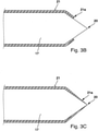
- Figure 3A illustrates the hydrophobic surface area 21, which can be produced by a water-repellent coating of the electrode 17.
- the electrode 17, which consists for example of tungsten or another metal, is provided on its outer peripheral surface with a layer of a water-repellent material, for example PTFE, silicone oil or the like.
- the tip 20 or a section thereof is preferably left free, ie uncoated, the term "tip" meaning the entire tapering, for example conical area of the electrode 17 .
- the electrode 17 can also according to Figure 3B be provided with a coating up to the area of the tip, which forms the hydrophobic surface area 21 .
- the coating can extend with undiminished thickness up to its end 21a, or as it Figure 3C illustrated decrease in thickness continuously or in stages towards its end 21a.
- the electrode 17 itself can consist of high-grade steel, steel, tungsten, hard metal or another high-melting material.
- the water-repellent effect can result in the hydrophobic surface area 21 due to the low surface energy of the material used, which is preferably less than 20 mJ/m 2 .
- the hydrophobic effect in the surface area 21 can be achieved by microstructuring the surface.
- the surface area 21 is shaped in such a way that a large number of very small spike-like protrusions protrude radially from it. This is achieved, for example, by first providing the surface area 21 with a helical groove, for example by means of a laser, and then with axial grooves.
- the length of the remaining projections and their distances from one another are matched to one another in such a way that a drop of water lying on the tips of these projections with the meniscus forming between the projections breaks the bottom of the groove due to its own surface tension is not affected.
- Other methods for microstructuring or influencing the surface roughness can also be used, such as dry etching or the application of nanoparticles.
- the tip 20 can be found to be hydrophobic due to the large curvature of its cone surface and tip.
- the holder 19 can have a hydrophobic surface area 22 which occupies the surface of the holder 19 in whole or in part.
- the hydrophobic surface area 22 can be achieved by suitable microstructuring of the surface or by coating it with water-repellent material. The description given above for the electrode 17 and the hydrophobic surface region 21 applies accordingly to the structuring of the surface or the coating materials.
- the tube 14 can be hydrophobic on the inside and/or outside and have corresponding hydrophobic surface areas 23 , 24 .
- its front side can be hydrophobic. This can be achieved by a suitable choice of material, for example by the tube 14 being made of PTFE.
- the hydrophobic effect of its surface can be increased by microstructuring and/or coating or choice of material, as explained above.
- the plasma probe 10 described so far works as follows: In operation, a gas flow, for example an argon flow, of a defined size flows through the channel 14a.
- the electrode 17 is, for example, with high-frequency AC voltage applied.
- the patient is connected to a neutral electrode. Starting from the tip 20, a plasma flow is now formed, which impinges on the tissue.
- liquid for example water, body fluid, rinsing liquid or the like
- the hydrophobic surface areas 21 as well as 22, 23, 24 prevent liquids from penetrating into the channel 14a or at least liquid droplets from settling in the channel 14a and on the electrode 17. Even a very small gas flow is therefore sufficient to prevent the electrode 17 and to free the channel 14a of liquid that has penetrated.
- the electrode 17, which has remained dry to this extent, can easily ignite at a large distance from the tissue. A gas flow that is kept low supports the ignitability.
- figure 4 illustrates a modified plasma probe 10, which is in addition to the plasma probe 10 according to figure 2 a ceramic insert 30 in the distal end 15 of the tube 14 .
- This has a hollow elongated shaft 31 which is pushed into the hose 14 .
- the channel 14a extends through the hose 14 and the shaft 31 to the outflow opening 16.
- the tip 20 of the electrode 17 is preferably in the insert 30 in arranged in the vicinity of the outflow opening 16 .
- the shaft 31 is used for heat distribution and dissipation.
- the insert 30 can be provided with a hydrophobic surface area 25 on the outside in the area of its distal end. Likewise, it can have a hydrophobic surface area 26 on the inside of its wall.
- the water-repellent effect of the surface areas 25, 26 can be achieved in any of the ways described above by selecting a suitable material and/or structuring the surface. Otherwise applies in connection with the Figures 1 to 2 according to the description given.
- the plasma probe 10 after figure 2 is in the Figures 5 and 6 shown separately again.
- the holder 19 can be designed as a cooling element and have one or more recesses on its tube-side edges, which minimize the contact surface with the tube.
- the holder 19 can be made of a metal, a ceramic material or a plastic or an elastomer such as silicone.
- flow channels 33, 34 are provided, through which gas, for example argon, can flow to the open hose end.
- figure 9 illustrates the exiting gas flow 35 and the plasma forming therein.
- the electrode 17 has a hydrophobic surface region 21 which preferably extends from the tip 20 to the holder 19.
- FIG. The holder 19 can also have hydrophobic surface areas 27, 28, in particular on its end face and/or in the flow channels 33, 34.
- the surface areas 27, 28 can be hydrophobic because the holder 19 itself consists of hydrophobic material, because it is coated with hydrophobic material and/or because its Surface is microstructured in terms of a lotus effect.
- the explanation given in connection with the electrode 17 applies accordingly to the microstructuring. Incidentally, the previous description of the Figures 1 to 4 for the embodiment according to Figures 5 and 6 additionally correspond.
- FIG 7 A further modified embodiment of the plasma probe 10 is shown in figure 7 illustrated.
- the description of the plasma probe 10 initially applies to this embodiment Figure 5 and 6 .
- the electrode 17 is hollow and thus designed without a point. It delimits a narrow channel 36.
- the electrode 17, which is thus designed as a small tube, is in turn connected to the wire 18 or other conductor. Its distal end does not protrude through the outflow opening 16 .
- the electrode 17 again carries the hydrophobic coating, for example.
- the surface area 21 can be hydrophobic because the electrode 17 itself consists of hydrophobic material, because it is coated with hydrophobic material and/or because its surface is microstructured in the sense of a lotus effect.
- FIG figure 8 A further modification of the plasma probe 10 according to the invention results from FIG figure 8 .
- the plasma probe 10 shown there has two holders 19a, 19b for supporting the electrode 17, which holders 19a, 19b pass through the lumen of the tube and can be arranged rotated about the electrode 17 in relation to one another.
- Each of the elements mentioned, in particular the electrode 17 and one of the holders 19a, 19b or both, can have a hydrophobic surface and consist of hydrophobic material or be made hydrophobic by coating with hydrophobic material or surface structuring.
- the electrode 17 does not necessarily have to stand back within the channel 15 behind the outflow opening 16 . It's like looking at the plasma probe 10 after figure 10 can be seen, it is also possible to lead the electrode 17 out of the outflow opening 16 .
- the electrode 17 is preferably provided with a blunt, preferably insulating body 37, for example a ceramic ball, which prevents direct galvanic contact between the electrode 17 and the surrounding biological tissue as well as mechanical damage to the tissue by the electrode 17.
- the electrode 17 can be removed from a holder 19 as shown in figure 10 is shown, or similar by several holders figure 8 be worn.
- the electrode 17 can have a tip 38 that is arranged in front of the outflow opening 16 and extends radially away from the electrode 17 .
- the electrode 17 can in turn have the hydrophobic surface area 21 .
- a further hydrophobic surface area 29 can be formed on the insulator 37 and occupy this completely or partially.
- the surface area 29 can be hydrophobic because the insulator 37 itself consists of hydrophobic material, because it is coated with hydrophobic material and/or because its surface is microstructured in the sense of a lotus effect. Otherwise, the previous descriptions apply correspondingly, in particular with regard to the formation of hydrophobic surface areas 21 to 27 .
- a hollow-cylindrical insert for thermal protection of the hose 14 can be inserted into the distal end 15 of the hose 14 .
- the inner diameter of this insert can correspond to that of the channel 14a or can be slightly smaller be than this.
- the insert can be hydrophobic, in particular on its inner wall and/or on at least one of its end faces. For this purpose, it can itself consist of hydrophobic material, be coated with hydrophobic material and/or be microstructured on the surface in the sense of a lotus effect.
- a plasma probe 10 according to the invention has a fluid line 14, which is preferably designed as a hose, and an electrode 17 arranged therein, the tip 20 of which is in the vicinity of the outflow opening 16.
- the electrode 17 has a hydrophobic surface area 21 . Additional elements of the plasma probe 10, in particular in the vicinity of the outflow opening 16, can optionally be equipped with hydrophobic surfaces. Such a probe has a significantly improved ability to ignite and, due to the constancy of the resulting discharge base point, improved stability.
Landscapes
- Health & Medical Sciences (AREA)
- Engineering & Computer Science (AREA)
- Surgery (AREA)
- Life Sciences & Earth Sciences (AREA)
- Physics & Mathematics (AREA)
- Plasma & Fusion (AREA)
- Heart & Thoracic Surgery (AREA)
- Veterinary Medicine (AREA)
- Nuclear Medicine, Radiotherapy & Molecular Imaging (AREA)
- Biomedical Technology (AREA)
- Otolaryngology (AREA)
- Medical Informatics (AREA)
- Molecular Biology (AREA)
- Animal Behavior & Ethology (AREA)
- General Health & Medical Sciences (AREA)
- Public Health (AREA)
- Cardiology (AREA)
- Spectroscopy & Molecular Physics (AREA)
- Surgical Instruments (AREA)
- Endoscopes (AREA)
- Investigating, Analyzing Materials By Fluorescence Or Luminescence (AREA)
Abstract
Description
- Die Erfindung betrifft eine Plasmasonde, insbesondere zur Plasmakoagulation von biologischem Gewebe. Weiter insbesondere betrifft die Erfindung eine Plasmasonde zum endoskopischen Einsatz.
- Aus der
DE 69636399 T2 ist eine Plasmasonde bekannt, die aus einem Rohr aus biegsamen Material besteht. Dieses Rohr wird durch einen Arbeitskanal eines Endoskops in den Körper eines Patienten geführt. Das Rohr weist ein Endstück auf, das aus einem temperaturbeständigen Material wie PTFE oder Keramik gefertigt ist. Ebenso kann das Rohr aus PTFE (Polytetrafluoräthylen) bestehen. In dem von dem Rohr und dem Endstück umschlossenen Kanal ist eine Elektrode angeordnet, deren Spitze aus der Öffnung des Rohrs bzw. des Endstücks nicht herausragt. Die Elektrode ist an eine Spannungsquelle angeschlossen. Der von dem Rohr umschlossene Kanal wird von Inertgas, beispielsweise Argon, durchströmt, sodass von der Sonde ein Plasmastrahl ausgeht. Eine Regulationseinheit gestattet dabei die Einstellung des Volumenstroms des Gases, die zumindest zwei verschieden große Gasströme bereitstellen kann. Im Standby-Betrieb ist der Gasstrom gering. Um sicherzustellen, dass in die Sonde eingedrungene Fluide bei Plasmazündung aus der Sonde wieder ausgetrieben sind, wird der Gasstrom während des Betriebs erhöht. Dadurch kann vermieden werden, dass sich in dem Rohr Blutreste ansammeln, was bei einer späteren Operation an einem anderen Patienten die Gefahr einer Infektion hervorrufen würde (siehe Abschnitt [0040]). - Aus der
DE 100 30 111 B4 ist eine weitere Plasmasonde bekannt, die aus einem dünnen Schlauch mit einem distalen hitzebeständigen Endstück und einer in dem Lumen des Schlauchs angeordnete Elektrode besteht. Die Elektrode wird insbesondere durch ein mit einer distalen Spitze versehenes Blech gebildet, dessen Längskanten sich an der Innenseite des Schlauchs abstützen. - Aus der
EP 0 957 793 B2 ist eine Plasmasonde mit einem Schlauch aus PTFE oder einem ähnlichen Material bekannt. Dieser Schlauch ist am distalen Ende mit einem Endstück versehen, das aus PTFE oder aus Keramik besteht. In dem Schlauch ist eine Elektrode angeordnet, die von dem von dem Schlauch herangeführten Edelgas umströmt wird und einen Plasmastrahl bildet. Wiederum kann der Gasstrom in Standby-Phasen verringert und bei Aktivierung erhöht werden, um ein Eindringen von Körperflüssigkeiten und Verschleppung derselben durch die Sonde auf andere Patienten zu vermeiden. - Weiter wird in der
EP 0 957 793 B2 eine Plasmasonde vorgeschlagen, deren Endstück aus Keramik besteht. Unmittelbar an das proximale Ende des hohlen Schafts des keramischen Endstücks ist eine rohrförmige Elektrode angeschlossen, deren Innendurchmesser mit dem Innendurchmesser des keramischen Endstücks übereinstimmt. Diese Anordnung dient zur Koagulation großer Gewebeflächen. - Im praktischen Betrieb zeigen die vorbeschriebenen Sonden gelegentlich schlechtes Zündverhalten. Dies bedeutet, dass zum Aufbau einer Plasmaentladung entweder besonders hohe Spannung genutzt werden müssen oder die Sonde sehr nahe an das zu behandelnde Gewebe herangeführt werden muss.
- Davon ausgehend ist es Aufgabe der Erfindung, eine Plasmasonde mit verbessertem Zündverhalten anzugeben.
- Diese Aufgabe wird mit der Plasmasonde nach Anspruch 1 gelöst:
Die erfindungsgemäße Plasmasonde weist eine flexible Fluidleitung auf, die beispielsweise durch einen dünnen Schlauch aus einem geeigneten Kunststoff, wie beispielsweise PTFE oder einem anderen geeigneten Kunststoff, bestehen kann. Die Fluidleitung begrenzt wenigstens einen Kanal, dessen proximales Ende mit einer Gasquelle verbindbar ist. Die Gasquelle dient dazu, den Kanal mit einem definierten Gasstrom zu versorgen, der an einer an dem distalen Ende der Fluidleitung ausgebildeten Ausströmöffnung austritt. - Weiter weist die Plasmasonde eine Elektrode auf, die über eine elektrische Leitung an eine elektrische Quelle anschließbar ist. Die Leitung kann ein sich durch den Kanal erstreckender Draht, eine Litze oder dergleichen oder ein an oder in der Wandung des Schlauchs geführter Leiter sein. Die elektrische Quelle kann ein Hochfrequenzgenerator sein, wie er in medizinischen Geräten zur Versorgung solcher Sonden vorhanden ist. Die Elektrode ist vorzugsweise in Nachbarschaft zu der Ausströmöffnung angeordnet. Das vorzugsweise spitz ausgebildete Ende der Elektrode kann in dem Kanal vorzugsweise so angeordnet sein, dass es nicht aus der Ausströmöffnung herausragt. Damit ist eine Verletzung von biologischem Gewebe durch mechanische Einwirkung der Elektrode ausgeschlossen. Alternativ kann sich die Elektrode durch die Ausströmöffnung hindurch erstrecken und endseitig einen stumpfen, vorzugsweise elektrisch isolierenden, Körper tragen, um wiederum Verletzungen von Gewebe zu vermeiden. Eine solche Sonde eignet sich für die omnidirektionale laterale Plasmaabgabe.
- Erfindungsgemäß ist an der Elektrode ein hydrophober Oberflächenbereich ausgebildet. Vorzugsweise betrifft dies insbesondere einen dem distalen Ende der Elektrode nahen oder an das distale Ende der Elektrode angrenzenden Abschnitt der Elektrode. Die Oberfläche der Elektrode kann auch insgesamt hydrophob ausgebildet sein.
- Durch die hydrophobe Ausbildung der Oberfläche der Elektrode wird deren Zündverhalten wesentlich verbessert. Wenn beim Einführen der Plasmasonde in das Endoskop Flüssigkeiten, beispielsweise Spülflüssigkeit, die Plasmasonde benetzen, neigen solche Flüssigkeiten auch zum Eindringen in die offene Ausströmöffnung der Plasmasonde. Solche Flüssigkeitströpfchen können den Gasstrom beeinträchtigen, Turbulenzen und Asymmetrien in der Gasströmung erzeugen und die Elektronenemission an der Spitze der Elektrode behindern. Ist die Elektrode hingegen wasserabweisend (hydrophob), werden solche Effekte reduziert oder vermieden.
- Der hydrophobe Oberflächenbereich der Elektrode verhindert auch, dass sich während des Betriebs der Plasmasonde biologisches Gewebe, Gewebeflüssigkeit oder aus dem biologischen Gewebe herrührende Produkte an der Elektrode anlagern und deren Oberflächenleitfähigkeit verändern. Damit wird auch ein Wandern des Entladungsfußpunkts und insbesondere ein Wandern des Entladungsfußpunkts von der Elektrodenspitze weg in den Kanal der Sonde hinein unterbunden. So wird auch die sonst drohende thermische Überbelastung der Sonde verhindert. Eine solche thermische Überbeanspruchung könnte sonst auch zur Verformung des Fluidleiters führen, was wiederum die Gasströmung und die Ausbildung des Plasmastroms massiv behindern würde. Auch könnte bei entsprechender Sondenschädigung ein direkter Kontakt zwischen Elektrode und Gewebe erfolgen. Diese Folgewirkungen eines wandernden Entladungsfußpunkts vermeidet die Erfindung weitgehend oder ganz.
- Die wasserabweisende Ausbildung der Elektrode, insbesondere des spitzennahen Oberflächenbereichs derselben, führt außerdem zu erhöhter Zündwilligkeit, insbesondere bei widrigen, d.h., besonders nassen Einsatzbedingungen.
- Die erfindungsgemäße Plasmasonde kann eine Fluidleitung aufweisen, die selbst aus wärmebeständigem Material besteht oder an ihrem distalen Ende mit einem wärmebeständigen Endstück versehen ist, durch das sich der Kanal erstreckt. Das Endstück kann einen Innendurchmesser aufweisen, der mit dem Innendurchmesser des Schlauchs übereinstimmt oder auch geringfügig kleiner ist als dieser. Vorzugsweise erstreckt sich die Elektrode wenigstens teilweise in das Endstück, sodass der Entladungsfußpunkt kurz vor der Ausströmöffnung innerhalb des Endstücks angeordnet ist.
- Zusätzlich zu dem an der Elektrode ausgebildeten hydrophoben Oberflächenbereich können weitere hydrophobe Oberflächenbereiche vorgesehen sein. Dadurch können Kapillareffekte verhindert werden. Das heißt es wird einerseits ein leichteres Abblasen von Flüssigkeit ermöglicht und es könnte durch die Verminderung von Kapillarkräften die Flüssigkeitsaufnahme reduziert werden. Dazu können das Endstück und/oder der Schlauch insbesondere innen, an den Kanal angrenzend, bedarfsweise jedoch auch um die Ausströmöffnung herum und/oder an der Außenseite des Endstücks und/oder des Schlauchs hydrophobe Oberflächenbereiche aufweisen. Mit diesen Maßnahmen lassen sich Zündwilligkeit und Standfestigkeit der Sonde in besonderer Weise fördern.
- Darüber hinaus ist es möglich, die Elektrode hohl auszubilden, sodass die Elektrode einen von Gas durchströmbaren Kanal aufweist. Diese Elektrode kann insbesondere in der Nähe ihres distalen Endes oder auch insgesamt an ihrer Außenseite mit einer hydrophoben Oberfläche versehen sein. Es ist auch möglich, den von der Elektrode umschlossenen Kanal mit einer hydrophoben Oberfläche zu versehen.
- Weiter ist es möglich, zur Lagerung der Elektrode in dem Kanal und/oder zur Beeinflussung der Gasströmung ein Strömungsleitelement aus Metall oder einem elektrischen Isolator, wie Kunststoff oder Keramik vorzusehen, welches Strömungsleitelement dazu eingerichtet sein kann, den Gasstrom im Zentrum des Querschnitts, d.h., in Nachbarschaft der Elektrode im Vergleich zu Randbereichen des Querschnitts zu drosseln. Auch diese Maßnahme dient der Erhöhung der Zündwilligkeit. Auch das Strömungsleitelement kann mit einer hydrophoben Oberfläche ausgestattet und dazu z.B. mit einer hydrophoben Oberflächenstruktur oder Beschichtung versehen sein.
- Um die gewünschten Oberflächenabschnitte hydrophob zu gestalten, können diese mit einer hydrophoben Beschichtung versehen sein, beispielsweise Silikonöl, Fluoropolymere, wie z.B. Polytetrafluoräthylen, Parylene, PFA (Perfluoroalkoxy), Polyamid, Polyethylen, einem SilikonElastomer oder dergleichen. Hydrophobe Beschichtungen können z.B. durch einen PVD oder CVD-Prozess aufgebracht werden. Zusätzlich oder alternativ ist es möglich, die wasserabweisende Wirkung der betreffenden Oberflächenbereiche durch Mikrostrukturierung der Oberflächen zu erzielen. Dazu können die betreffenden Oberflächenbereiche mit einer Vielzahl sich kreuzender feinster Nuten versehen sein, die ein Raster winziger Vorsprünge freilassen. Diese Vorsprünge halten Flüssigkeitstropfen mit ihren Stirnflächen von den Nutböden fern, sodass Flüssigkeit leicht abperlen kann.
- Weitere Einzelheiten vorteilhafter Ausführungsformen der Erfindung sind Gegenstand von Unteransprüchen, sowie der Zeichnung oder der Beschreibung. Es zeigen:
-
Figur 1 ein medizinisches Gerät mit einer daran angeschlossenen Plasmasonde, in schematisierter Darstellung, -
Figur 2 die Plasmasonde nachFigur 1 , in längsgeschnittener Darstellung ihres distalen Endabschnitts, -
Figur 3A - 3D die Elektrode der Plasmasonde nachFigur 2 , in längsgeschnittener vergrößerter Darstellung ihres distalen Endes, in unterschiedlichen Ausführungsformen, -
Figur 4 eine abgewandelte Ausführungsform der erfindungsgemäßen Plasmasonde, in Längsschnittdarstellung ihres distalen Endes, -
Figur 5 eine weitere Ausführungsform einer erfindungsgemäßen Plasmasonde, in längsgeschnittener Darstellung ihres distalen Endes, -
Figur 6 die Plasmasonde nachFigur 5 mit Blickrichtung auf das distale Ende, -
Figur 7 und 8 weitere Ausführungsformen erfindungsgemäßer Plasmasonden, jeweils in Längsschnittdarstellung ihres distalen Endes, -
Figur 9 die Plasmasonde nachFigur 8 unter Veranschaulichung des Strömungsprofils, -
Figur 10 eine Ausführungsform der erfindungsgemäßen Plasmasonde, in längsgeschnittener Darstellung ihres distalen Endes. - In
Figur 1 ist eine Plasmasonde 10 veranschaulicht, wie sie durch ein nicht weiter veranschaulichtes Endoskop zur Durchführung einer Plasmabehandlung an einem Patienten Anwendung finden kann. Die Plasmasonde 10 ist dazu an ein speisendes Gerät 11 oder eine Geräteanordnung angeschlossen, das oder die zur Versorgung der Plasmasonde 10 mit elektrischem Strom und einem Inertgas dient. Das Gerät weist dazu einen elektrischen Generator, beispielsweise einen HF-Generator 12 auf, der dazu geeignet ist, eine hochfrequente Wechselspannung abzugeben, die ausreicht, um eine Plasmaentladung zu zünden und aufrecht zu erhalten. - Zur Versorgung mit Inertgas dient eine Gasquelle 13, die ein geeignetes Gas, beispielsweise Argon, liefert. Die Gasquelle 13 ist dabei darauf eingerichtet, Gas dosiert und kontrolliert zu liefern, um die Plasmasonde 10 mit einem geeigneten Volumenstrom Gas zu versorgen.
- Die Plasmasonde 10 ist an ihrem proximalen Ende, beispielsweise über einen geeigneten Stecker, an den HF-Generator 12 und an die Gasquelle 13 angeschlossen.
- Die Plasmasonde 10 besteht im Wesentlichen aus einer flexiblen Fluidleitung 14 beispielsweise in Gestalt eines Kunststoffschlauchs. Dieser kann aus PTFE oder einem anderen für medizinische Anwendungen geeigneten Kunststoff bestehen. Die Fluidleitung 14 umschließt einen Kanal 14a, der zu der an dem distalen Ende 15 des Schlauchs 14 vorgesehenen Ausströmöffnung 16 führt. In dem distalen Ende 15 ist eine Elektrode 17 beispielsweise in Form eines endseitig zugespitzten metallischen Stifts oder eines Drahts angeordnet. Während das distale Ende der Elektrode 17 in dem Kanal 14a vorzugsweise etwa mittig so angeordnet ist, dass es nicht aus der Ausströmöffnung 16 herausragt, ist das proximale Ende der Elektrode 17 mit einer geeigneten elektrischen Leitung 18 verbunden, die zu dem Generator 12 führt.
- Zur Positionierung der Elektrode 17 in den Kanal 14a kann eine geeignete Halteeinrichtung vorgesehen sein, beispielsweise ein diametral in dem Kanal 14a positionierter plattenförmiger Halter 19, der sich mit beiden Längskanten an der Innenwandung des Schlauchs 14 abstützt. Die Elektrode 17 kann mit dem Halter 19 verklemmt, verschweißt oder anderweitig verbunden sein. Es ist auch möglich, die Elektrode 17 und den Halter 18 aus ein einziges Teil, beispielsweise ein rhombisches Blechteil auszubilden, dessen Spitze die Position der Spitze 20 der Elektrode 17 einnimmt und dessen Längskanten sich innen an dem Schlauch 14 abstützen.
- Erfindungsgemäß weist die Elektrode 17 mindestens einen hydrophoben Oberflächenbereich 21 auf. Dieser umgibt vorzugsweise wenigstens das distale Ende der Elektrode 17. Insbesondere kann der hydrophoben Flächenbereich 21 die zylindrische Außenumfangsfläche der Elektrode 17 einnehmen.
Figur 3A veranschaulicht den hydrophoben Flächenbereich 21, der durch eine wasserabweisende Beschichtung der Elektrode 17 erzeugt sein kann. Die beispielsweise aus Wolfram oder einem anderen Metall bestehende Elektrode 17 ist dazu an ihrer Außenumfangsfläche mit einer Schicht aus einem wasserabweisenden Material beispielsweise PTFE, Silikonöl oder dergleichen versehen. Vorzugsweise ist die Spitze 20 oder ein Abschnitt derselben jedoch freigelassen, also unbeschichtet, wobei unter dem Begriff der "Spitze" der gesamte sich verjüngende, z.B. kegelförmige Bereich der Elektrode 17 gemeint ist. - Die Elektrode 17 kann auch gemäß
Figur 3B bis in den Bereich der Spitze hinein mit einer Beschichtung versehen sein, die den hydrophoben Flächenbereich 21 bildet. Die Beschichtung kann sich Dabei mit unverminderter Dicke bis zu ihrem Ende 21a erstrecken, oder, wie esFigur 3C veranschaulicht, zu ihrem Ende 21a hin in ihrer Dicke kontinuierlich oder in Stufen abnehmen. Außerdem kann jede der vorbeschriebenen Elektroden 17, wie esFigur 3D am Beispiel der Elektrode nachFigur 3B darstellt, eine elektrisch gut leitende Schicht 17a tragen, wie z.B. eine Schicht aus Silber. Diese wird von der Beschichtung des hydrophoben Flächenbereichs 21 zu der oder bis in den Bereich der Spitze 20 bedeckt. Die Elektrode 17 selbst kann bei allen Ausführungsbeispielen aus Edelstahl, Stahl, Wolfram, Hartmetall oder einem anderen hochschmelzenden Material bestehen. - Die wasserabweisende Wirkung kann sich in dem hydrophoben Flächenbereich 21 durch die geringe Oberflächenenergie des verwendeten Materials ergeben, die vorzugsweise geringer als 20 mJ/m2 ist. Zusätzlich oder alternativ kann die hydrophobe Wirkung in dem Flächenbereich 21 durch eine Mikrostrukturierung der Oberfläche erreicht werden. Dazu wird der Oberflächenbereich 21 so geformt, dass von ihm eine Vielzahl sehr kleiner stachelartiger Forstätze radial vorstehen. Beispielsweise wird dies erreicht, indem der Oberflächenbereich 21 zunächst beispielsweise mittels Lasers mit einer Schraubennut und nachfolgend mit axialen Nuten versehen wird. Die Länge der verbleibenden Vorsprünge und deren Abstände zueinander sind dabei so aufeinander abgestimmt, dass ein auf den Spitzen dieser Vorsprünge liegender Wassertropfen mit dem sich zwischen den Vorsprüngen ausbildenden Meniskus den Nutboden aufgrund seiner eigenen Oberflächenspannung nicht berührt. Es sind auch andere Verfahren zur Mikrostrukturierung oder Beeinflussung der Oberflächenrauheit anwendbar, wie z.B. Trockenätzen oder das Aufbringen von Nanopartikeln.
- Die Spitze 20 kann sich infolge ihrer großen Krümmung ihrer Kegelfläche und deren Spitze als hydrophob erweisen.
- Des Weiteren kann der Halter 19 einen hydrophoben Oberflächenbereich 22 aufweisen, der die Oberfläche des Halters 19 ganz oder teilweise einnimmt. Wiederum kann der hydrophobe Oberflächenbereich 22 durch geeignete Mikrostrukturierung der Oberfläche oder durch Beschichtung derselben mit wasserabweisendem Material erreicht werden. Zu der Strukturierung der Oberfläche oder den Beschichtungsmaterialien gilt die obige zu der Elektrode 17 und dem hydrophoben Oberflächenbereich 21 gegebenen Beschreibung entsprechend.
- Zudem kann der Schlauch 14 innen und/oder außen hydrophob sein und entsprechende hydrophobe Oberflächenbereiche 23, 24 aufweisen. Ebenso kann seine Stirnseite hydrophob sein. Erreicht werden kann dies durch geeignete Materialwahl, beispielsweise indem der Schlauch 14 aus PTFE besteht. Die hydrophobe Wirkung seiner Oberfläche kann durch Mikrostrukturierung und oder Beschichtung oder Materialwahl wie vorstehend erläutert erhöht werden.
- Die insoweit beschriebene Plasmasonde 10 arbeitet wie folgt:
In Betrieb strömt ein Gasstrom, beispielsweise ein Argon-Strom definierter Größe durch den Kanal 14a. Die Elektrode 17 ist z.B. mit hochfrequenter Wechselspannung beaufschlagt. Der Patient ist an eine Neutralelektrode angeschlossen. Ausgehend von der Spitze 20 bildet sich nun ein Plasmastrom, der auf das Gewebe trifft. - Bei Betriebsunterbrechung oder vor Betriebsbeginn kann Flüssigkeit, beispielsweise Wasser, Körperflüssigkeit, Spülflüssigkeit oder dergleichen an die Ausströmöffnung 16 gelangen. Jedoch vermeiden die hydrophoben Oberflächenbereiche 21 sowie auch 22, 23, 24 das Eindringen der Flüssigkeiten in den Kanal 14a oder wenigstens das Festsetzen von Flüssigkeitstropfen in dem Kanal 14a und an der Elektrode 17. Schon ein sehr geringer Gasstrom reicht somit aus, die Elektrode 17 und den Kanal 14a von eingedrungener Flüssigkeit zu befreien. Die insoweit trocken gebliebene Elektrode 17 kann mit großem Abstand zum Gewebe leicht zünden. Ein dabei gering gehaltener Gasstrom unterstützt die Zündwilligkeit.
- Gleiches gilt beim Einführen der Plasmasonde 10 durch ein Endoskop in den Patienten vor Behandlungsbeginn. Auch in diesem Fall kann Flüssigkeit in den Kanal 14a vordringen, die dann schon mit sehr geringen Gasflüssen von der Elektrode 17 fortgespült werden kann.
- An der insoweit grundsätzlich erläuterten Erfindung sind zahlreiche Abwandlungen möglich:
Figur 4 veranschaulicht eine abgewandelte Plasmasonde 10, die zusätzlich zu der Plasmasonde 10 nachFigur 2 in dem distalen Ende 15 des Schlauchs 14 einen keramischen Einsatz 30 aufweist. Dieser weist einen hohl ausgebildeten länglichen Schaft 31 auf, der in den Schlauch 14 eingeschoben ist. Der Kanal 14a erstreckt sich durch den Schlauch 14 und den Schaft 31 bis zu der Ausströmöffnung 16. Die Spitze 20 der Elektrode 17 ist in dem Einsatz 30 vorzugsweise in der Nähe der Ausströmöffnung 16 angeordnet. Der Schaft 31 dient der Wärmeverteilung und Ableitung. Der Einsatz 30 kann im Bereich seines distalen Endes außen mit einem hydrophoben Oberflächenbereich 25 versehen sein. Gleichfalls kann er innen an seiner Wandung einen hydrophoben Oberflächenbereich 26 aufweisen. Die wasserabweisende Wirkung der Oberflächenbereiche 25, 26 kann auf jede der vorbeschriebenen Weisen durch geeignete Stoffwahl und/oder Strukturierung der Oberfläche erreicht werden. Ansonsten gilt die im Zusammenhang mit denFiguren 1 bis 2 gegebene Beschreibung entsprechend. - Die Plasmasonde 10 nach
Figur 2 ist in denFiguren 5 und 6 nochmals gesondert dargestellt. Der Halter 19 kann als Kühlelement ausgebildet sein und an seinen schlauchseitigen Rändern eine oder mehrere Ausnehmungen aufweisen, die die Berührungsfläche zu dem Schlauch minimieren. Der Halter 19 kann aus einem Metall, einem Keramikmaterial oder einem Kunststoff oder einem Elastomer, wie z.B. Silicon, gefertigt sein. Zu beiden Seiten des Halters 19 sind, wieFigur 6 zeigt, Strömungskanäle 33, 34 vorgesehen, durch die Gas, z.B. Argon zu dem offenen Schlauchende hin strömen kann.Figur 9 veranschaulicht die austretende Gasströmung 35 und das sich darin ausbildende Plasma. - Wiederum kann, wie
Figur 5 zeigt, die Elektrode 17 einen hydrophoben Oberflächenbereich 21 aufweisen, der sich vorzugsweise von der Spitze 20 bis zum den Halter 19 erstreckt. Auch kann der Halter 19 insbesondere an seiner Stirnseite und/oder in den Strömungskanälen 33, 34 hydrophobe Oberflächenbereiche 27, 28 aufweisen. Die Oberflächenbereiche 27, 28 können hydrophob sein, weil der Halter 19 selbst aus hydrophobem Material besteht, weil es mit hydrophobem Material beschichtet ist und/oder weil seine Oberfläche im Sinne eines Lotuseffekts mikrostrukturiert ist. Zur Mikrostrukturierung gilt die im Zusammenhang mit der Elektrode 17 gegebene Erläuterung entsprechend. Im Übrigen gilt auch die vorige Beschreibung derFiguren 1 bis 4 für die Ausführungsform nachFiguren 5 und 6 ergänzend entsprechen. - Eine weiter abgewandelte Ausführungsform der Plasmasonde 10 ist in
Figur 7 veranschaulicht. Für diese Ausführungsform gilt zunächst die Beschreibung der Plasmasonde 10 nachFigur 5 und 6 . Anders als dort ist die Elektrode 17 jedoch hohl und somit ohne Spitze ausgebildet. Sie umgrenzt einen engen Kanal 36. Die somit als Röhrchen ausgebildete Elektrode 17 ist wiederum mit dem Draht 18 oder sonstigen Leiter verbunden. Ihr distales Ende durchragt die Ausströmöffnung 16 nicht. An ihrer Außenseite trägt die Elektrode 17 z.B. wiederum die hydrophobe Beschichtung. Der Oberflächenbereich 21 kann hydrophob sein, weil die Elektrode 17 selbst aus hydrophobem Material besteht, weil sie mit hydrophobem Material beschichtet ist und/oder weil ihre Oberfläche im Sinne eines Lotuseffekts mikrostrukturiert ist. - Eine weitere Abwandlung der erfindungsgemäßen Plasmasonde 10 ergibt sich aus
Figur 8 . Die dort dargestellte Plasmasonde 10 weist zur Lagerung der Elektrode 17 zwei Halter 19a, 19b auf, die das Lumen des Schlauchs durchqueren und gegeneinander um die Elektrode 17 verdreht angeordnet sein können. Jedes der genannten Elemente, insbesondere die Elektrode 17 sowie einer der Halter 19a, 19b oder auch beide, können eine hydrophobe Oberfläche aufweisen und dazu aus hydrophoben Material bestehen oder durch Beschichtung mit hydrophoben Material oder Oberflächenstrukturierung hydrophob ausgestaltet sein. - Die Elektrode 17 muss nicht zwingend innerhalb des Kanals 15 hinter der Ausströmöffnung 16 zurückstehen. Es ist, wie sich an der Plasmasonde 10 nach
Figur 10 erkennen lässt, auch möglich, die Elektrode 17 aus der Ausströmöffnung 16 herauszuführen. In diesem Fall ist die Elektrode 17 vorzugsweise mit einem stumpfen, vorzugsweise isolierenden Körper 37, beispielsweise einer Keramikkugel, versehen, die einen direkten galvanischen Kontakt zwischen der Elektrode 17 und umgebenden biologischem Gewebe ebenso verhindert, wie eine mechanische Schädigung des Gewebes durch die Elektrode 17. Die Elektrode 17 kann von einem Halter 19, wie es inFigur 10 dargestellt ist, oder auch von mehreren Haltern ähnlichFigur 8 getragen sein. Als Entladungsfußpunkt kann die Elektrode 17 vor der Ausströmöffnung 16 angeordnete, sich radial von der Elektrode 17 weg erstreckende Spitze 38 aufweisen. Die Elektrode 17 kann wiederum den hydrophoben Oberflächenbereich 21 aufweisen. Ein weiterer hydrophober Oberflächenbereich 29 kann an dem Isolator 37 ausgebildet sein und diesen ganz oder teilweise einnehmen. Der Oberflächenbereich 29 kann hydrophob sein, weil der Isolator 37 selbst aus hydrophobem Material besteht, weil er mit hydrophobem Material beschichtet ist und/oder weil seine Oberfläche im Sinne eines Lotuseffekts mikrostrukturiert ist. Ansonsten gelten die vorigen Beschreibungen, insbesondere hinsichtlich der Ausbildung hydrophober Oberflächenbereiche 21 bis 27 entsprechend. - Bei allen Ausführungsformen gemäß
Figur 5 bis 10 kann in das distale Ende 15 des Schlauchs 14 ein hohlzylindrischer Einsatz zum thermischen Schutz des Schlauchs 14 eingesetzt sein. Der Innendurchmesser dieses Einsatzes kann dem des Kanals 14a entsprechen oder auch geringfügig geringer sein als dieser. der Einsatz kann insbesondere an seiner inneren Wandung und oder an wenigstens einer seiner Stirnseiten hydrophob sein. Dazu kann er selbst aus hydrophobem Material bestehen, mit hydrophobem Material beschichtet und/oder an der Oberfläche im Sinne eines Lotuseffekts mikrostrukturiert sein. - Eine erfindungsgemäße Plasmasonde 10 weist eine Fluidleitung 14, die vorzugsweise als Schlauch ausgebildet ist, und eine darin angeordnete Elektrode 17 auf, deren Spitze 20 in der Nähe der Ausströmöffnung 16 steht. Die Elektrode 17 weist einen hydrophob ausgebildeten Oberflächenbereich 21 auf. Optional können weitere Elemente der Plasmasonde 10, insbesondere in Nachbarschaft zu der Ausströmöffnung 16, mit hydrophoben Oberflächen ausgestattet sein. Eine solche Sonde weist eine deutlich verbesserte Zündwilligkeit und aufgrund der Konstanz des sich ergebenden Entladungsfußpunkts eine verbesserte Standfestigkeit auf.
-
- 10
- Plasmasonde
- 11
- Gerät
- 12
- HF-Generator
- 13
- Gasquelle
- 14
- Fluidleitung (Kunststoffschlauch)
- 15
- distales Ende der Fluidleitung
- 16
- Ausströmöffnung
- 17
- Elektrode
- 18
- Leitung
- 19
- Halter
- 20
- Spitze der Elektrode 17
- 21 - 29
- hydrophobe Oberflächenbereiche
- 21a
- Ende des hydrophoben Oberflächenbereichs
- 30
- Einsatz
- 31
- Schaft
- 32
- Ausnehmung
- 33
- Strömungskanal
- 34a
- Strömungskanal
- 35
- Gasströmung
- 36
- Kanal
- 37
- Isolator
- 38
- Spitzen
Claims (11)
- Plasmasonde (10), insbesondere zur Plasmakoagulation von biologischem Gewebe,
mit einer Fluidleitung (14), die wenigstens einen an eine Gasquelle (13) anschließbaren Kanal (14a) begrenzt, der zu einem distalen Ende (15) der Fluidleitung (14) führt und dort an einer Ausströmöffnung (16) endet,
mit einer in Nachbarschaft zu der Ausströmöffnung (16) angeordneten Elektrode (17), die über eine Leitung (18) an eine, elektrische Quelle (12) anschließbar ist,
dadurch gekennzeichnet, dass an der Elektrode (17) ein hydrophober Oberflächenbereich (21) ausgebildet ist. - Plasmasonde nach Anspruch 1, dadurch gekennzeichnet, dass die Fluidleitung (14) ein flexibler Schlauch aus elektrisch isolierendem Material ist, in dessen distalen Ende (15) ein elektrisch isolierendes, hitzefestes Endstück (30) gehalten ist, durch das sich der Kanal (14a) erstreckt.
- Plasmasonde nach einem der vorstehenden Ansprüche, dadurch gekennzeichnet, dass die Elektrode (17) wenigstens teilweise in dem Endstück (30) angeordnet ist.
- Plasmasonde nach einem der vorstehenden Ansprüche 2 oder 3, dadurch gekennzeichnet, dass ein hydrophober Oberflächenbereich (26) zusätzlich an dem Endstück (30) und/oder an dem Schlauch (14) ausgebildet ist.
- Plasmasonde nach einem der vorstehenden Ansprüche, dadurch gekennzeichnet, dass die Elektrode (17) hohl ausgebildet ist und an ihrer Außenseite einen hydrophoben Oberflächenbereich (21) aufweist.
- Plasmasonde nach einem der vorstehenden Ansprüche, dadurch gekennzeichnet, dass an oder in dem distalen Ende (15) ein Halter (19) angeordnet ist, der mit der Elektrode (17) verbunden ist und diese in der Fluidleitung (14) fixiert.
- Plasmasonde nach Anspruch 6, dadurch gekennzeichnet, dass an dem Halter (19) zusätzlich ein hydrophober Oberflächenbereich (27, 28) ausgebildet ist.
- Plasmasonde nach einem der vorstehenden Ansprüche, dadurch gekennzeichnet, dass der hydrophobe Oberflächenbereich (21) mit Wasser einen Benetzungswinkel (α) festlegt, der größer als 90° ist.
- Plasmasonde nach einem der vorstehenden Ansprüche, dadurch gekennzeichnet, dass die Oberflächenenergie des hydrophoben Bereichs (21) kleiner als 20 mJ/m2 ist.
- Plasmasonde nach einem der vorstehenden Ansprüche, dadurch gekennzeichnet, dass der hydrophobe Bereich (21) durch hydrophobes Material gebildet ist.
- Plasmasonde nach Anspruch 6, dadurch gekennzeichnet, dass der Halter (19) wenigstens zwei an der Elektrode (17) entlang führende Kanäle (33, 34) aufweist.
Priority Applications (6)
| Application Number | Priority Date | Filing Date | Title |
|---|---|---|---|
| EP20187417.9A EP3943029B1 (de) | 2020-07-23 | 2020-07-23 | Plasmasonde mit verbessertem zündverhalten |
| PL20187417.9T PL3943029T3 (pl) | 2020-07-23 | 2020-07-23 | Sonda plazmowa z ulepszonymi właściwościami zapłonu |
| BR102021013051-2A BR102021013051A2 (pt) | 2020-07-23 | 2021-06-30 | Sonda de plasma com comportamento de ignição aperfeiçoado |
| KR1020210090036A KR20220012815A (ko) | 2020-07-23 | 2021-07-09 | 점화 거동이 개선된 플라즈마 프로브 |
| JP2021117307A JP7664107B2 (ja) | 2020-07-23 | 2021-07-15 | 点火挙動が改善されたプラズマプローブ |
| CN202110836504.7A CN113967066B (zh) | 2020-07-23 | 2021-07-23 | 具有改进的点火行为的等离子体探针 |
Applications Claiming Priority (1)
| Application Number | Priority Date | Filing Date | Title |
|---|---|---|---|
| EP20187417.9A EP3943029B1 (de) | 2020-07-23 | 2020-07-23 | Plasmasonde mit verbessertem zündverhalten |
Publications (3)
| Publication Number | Publication Date |
|---|---|
| EP3943029A1 true EP3943029A1 (de) | 2022-01-26 |
| EP3943029B1 EP3943029B1 (de) | 2025-04-02 |
| EP3943029C0 EP3943029C0 (de) | 2025-04-02 |
Family
ID=71783908
Family Applications (1)
| Application Number | Title | Priority Date | Filing Date |
|---|---|---|---|
| EP20187417.9A Active EP3943029B1 (de) | 2020-07-23 | 2020-07-23 | Plasmasonde mit verbessertem zündverhalten |
Country Status (6)
| Country | Link |
|---|---|
| EP (1) | EP3943029B1 (de) |
| JP (1) | JP7664107B2 (de) |
| KR (1) | KR20220012815A (de) |
| CN (1) | CN113967066B (de) |
| BR (1) | BR102021013051A2 (de) |
| PL (1) | PL3943029T3 (de) |
Citations (4)
| Publication number | Priority date | Publication date | Assignee | Title |
|---|---|---|---|---|
| DE69636399T2 (de) | 1995-09-26 | 2007-09-27 | Erbe Elektromedizin Gmbh | Flexibler Argon-Plasma-Endoskopieagulator |
| DE10030111B4 (de) | 2000-06-19 | 2008-07-10 | Erbe Elektromedizin Gmbh | Sondenelektrode |
| US20180353233A1 (en) * | 2017-06-07 | 2018-12-13 | Erbe Elektromedizin Gmbh | Instrument With a Multistream Instrument Head for Argon Plasma Coagulation |
| US20200188014A1 (en) * | 2017-05-16 | 2020-06-18 | Smith & Nephew, Inc. | Electrosurgical systems and methods |
Family Cites Families (13)
| Publication number | Priority date | Publication date | Assignee | Title |
|---|---|---|---|---|
| US7566333B2 (en) * | 2003-08-11 | 2009-07-28 | Electromedical Associates Llc | Electrosurgical device with floating-potential electrode and methods of using the same |
| DE102009044512B4 (de) * | 2009-09-11 | 2021-08-12 | Erbe Elektromedizin Gmbh | Karbonisierungsverhinderungsvorrichtung |
| WO2012058456A2 (en) * | 2010-10-27 | 2012-05-03 | University Of Florida Research Foundation, Inc. | Method and apparatus for disinfecting and/or self-sterilizing a stethoscope using plasma energy |
| GB201117274D0 (en) | 2011-10-06 | 2011-11-16 | Gyrus Medical Ltd | Electrosurgical apparatus and system |
| US20130116682A1 (en) * | 2011-11-09 | 2013-05-09 | Colorado State University Research Foundation | Non-Stick Conductive Coating for Biomedical Applications |
| US9439677B2 (en) * | 2012-01-20 | 2016-09-13 | Iogyn, Inc. | Medical device and methods |
| CN204121167U (zh) * | 2014-09-28 | 2015-01-28 | 大连顺达微创科技有限公司 | 一种管状电极内侧供液方式的等离子体手术电极 |
| CN204121166U (zh) * | 2014-09-28 | 2015-01-28 | 大连顺达微创科技有限公司 | 一种倾斜微孔供液方式的等离子体手术电极 |
| CN107949336B (zh) * | 2015-08-27 | 2021-10-22 | 密涅瓦外科有限公司 | 组织切除装置 |
| US10368939B2 (en) * | 2015-10-29 | 2019-08-06 | Covidien Lp | Non-stick coated electrosurgical instruments and method for manufacturing the same |
| US10631396B2 (en) * | 2017-03-20 | 2020-04-21 | Nanova, Inc. | Device for generating and delivering low temperature plasma |
| US20210169565A1 (en) | 2017-05-16 | 2021-06-10 | Smith & Nephew, Inc. | Electrosurgical systems and methods |
| CN210141600U (zh) * | 2019-05-28 | 2020-03-13 | 宁波方太厨具有限公司 | 灶具火盖 |
-
2020
- 2020-07-23 PL PL20187417.9T patent/PL3943029T3/pl unknown
- 2020-07-23 EP EP20187417.9A patent/EP3943029B1/de active Active
-
2021
- 2021-06-30 BR BR102021013051-2A patent/BR102021013051A2/pt unknown
- 2021-07-09 KR KR1020210090036A patent/KR20220012815A/ko active Pending
- 2021-07-15 JP JP2021117307A patent/JP7664107B2/ja active Active
- 2021-07-23 CN CN202110836504.7A patent/CN113967066B/zh active Active
Patent Citations (5)
| Publication number | Priority date | Publication date | Assignee | Title |
|---|---|---|---|---|
| DE69636399T2 (de) | 1995-09-26 | 2007-09-27 | Erbe Elektromedizin Gmbh | Flexibler Argon-Plasma-Endoskopieagulator |
| EP0957793B2 (de) | 1995-09-26 | 2009-01-28 | Erbe Elektromedizin GmbH | Flexibler argon-plasma-endoskopiekoagulator |
| DE10030111B4 (de) | 2000-06-19 | 2008-07-10 | Erbe Elektromedizin Gmbh | Sondenelektrode |
| US20200188014A1 (en) * | 2017-05-16 | 2020-06-18 | Smith & Nephew, Inc. | Electrosurgical systems and methods |
| US20180353233A1 (en) * | 2017-06-07 | 2018-12-13 | Erbe Elektromedizin Gmbh | Instrument With a Multistream Instrument Head for Argon Plasma Coagulation |
Also Published As
| Publication number | Publication date |
|---|---|
| JP7664107B2 (ja) | 2025-04-17 |
| CN113967066A (zh) | 2022-01-25 |
| PL3943029T3 (pl) | 2025-07-14 |
| CN113967066B (zh) | 2025-02-25 |
| KR20220012815A (ko) | 2022-02-04 |
| BR102021013051A2 (pt) | 2022-03-03 |
| EP3943029B1 (de) | 2025-04-02 |
| EP3943029C0 (de) | 2025-04-02 |
| JP2022022135A (ja) | 2022-02-03 |
Similar Documents
| Publication | Publication Date | Title |
|---|---|---|
| DE10030111B4 (de) | Sondenelektrode | |
| DE69834825T2 (de) | Elektrochirurgisches gerät zur gewebeentfernung | |
| DE10128701B4 (de) | Sondenanordnung | |
| EP2948086B1 (de) | Bipolares resektoskop | |
| EP1044654B1 (de) | Anordnung zur elektro-thermischen Behandlung des menschlichen oder tierischen Körpers | |
| DE60220079T2 (de) | Selbst benetzende, bipolare trockenfeldelektroden für die endoskopische chirurgie | |
| EP0996381B1 (de) | Einrichtung zur koagulation biologischer gewebe mittels eines ionizierbaren gases | |
| EP3141203B1 (de) | Ablationseinrichtung zur grossflächigen mukosaablation | |
| EP3769707B1 (de) | Elektrodenanordnung | |
| EP3649974B1 (de) | Elektrodenanordnung für ein bipolares resektoskop sowie resektoskop | |
| EP1682023B1 (de) | Vorrichtung zur koagulation von gewebe | |
| DE102006006052B4 (de) | Hochfrequenz-Behandlungsgerät für ein Endoskop | |
| DE102007003836A1 (de) | Bipolares Instrument und Verfahren zur elektrochirurgischen Behandlung von Gewebe | |
| WO1997028751A2 (de) | Schneidvorrichtung zur elektrotomie | |
| EP3984480A1 (de) | Multilumensonde | |
| WO2021130229A1 (de) | Vorrichtungen zur enukleation intrakorporaler gewebebereiche | |
| DE3642077C2 (de) | Vorrichtung, mit einem Generator und einer damit verbundenen Applikationssonde | |
| DE102017127976A1 (de) | Elektrochirurgische Vorrichtung | |
| EP3943029B1 (de) | Plasmasonde mit verbessertem zündverhalten | |
| EP1646323B1 (de) | Chirurgische sonde | |
| DE10028413B4 (de) | Elektrochirurgisches Instrument mit reduzierter Elektrodenfläche | |
| EP4119080A1 (de) | Plasmasonde und verfahren zur montage ihrer elektrode | |
| DE102009004968B4 (de) | Strahlgenerator zur Erzeugung eines gebündelten Plasmastrahls | |
| EP4124307B1 (de) | Elektrochirurgisches instrument mit beweglicher elektrode | |
| EP4403123A1 (de) | Plasmasonde zur medizinischen behandlung von gewebe |
Legal Events
| Date | Code | Title | Description |
|---|---|---|---|
| PUAI | Public reference made under article 153(3) epc to a published international application that has entered the european phase |
Free format text: ORIGINAL CODE: 0009012 |
|
| STAA | Information on the status of an ep patent application or granted ep patent |
Free format text: STATUS: THE APPLICATION HAS BEEN PUBLISHED |
|
| AK | Designated contracting states |
Kind code of ref document: A1 Designated state(s): AL AT BE BG CH CY CZ DE DK EE ES FI FR GB GR HR HU IE IS IT LI LT LU LV MC MK MT NL NO PL PT RO RS SE SI SK SM TR |
|
| STAA | Information on the status of an ep patent application or granted ep patent |
Free format text: STATUS: REQUEST FOR EXAMINATION WAS MADE |
|
| 17P | Request for examination filed |
Effective date: 20220421 |
|
| RBV | Designated contracting states (corrected) |
Designated state(s): AL AT BE BG CH CY CZ DE DK EE ES FI FR GB GR HR HU IE IS IT LI LT LU LV MC MK MT NL NO PL PT RO RS SE SI SK SM TR |
|
| GRAP | Despatch of communication of intention to grant a patent |
Free format text: ORIGINAL CODE: EPIDOSNIGR1 |
|
| STAA | Information on the status of an ep patent application or granted ep patent |
Free format text: STATUS: GRANT OF PATENT IS INTENDED |
|
| INTG | Intention to grant announced |
Effective date: 20241126 |
|
| RIC1 | Information provided on ipc code assigned before grant |
Ipc: A61B 18/12 20060101ALN20241119BHEP Ipc: A61B 18/00 20060101ALN20241119BHEP Ipc: A61B 18/04 20060101AFI20241119BHEP |
|
| GRAS | Grant fee paid |
Free format text: ORIGINAL CODE: EPIDOSNIGR3 |
|
| GRAA | (expected) grant |
Free format text: ORIGINAL CODE: 0009210 |
|
| STAA | Information on the status of an ep patent application or granted ep patent |
Free format text: STATUS: THE PATENT HAS BEEN GRANTED |
|
| AK | Designated contracting states |
Kind code of ref document: B1 Designated state(s): AL AT BE BG CH CY CZ DE DK EE ES FI FR GB GR HR HU IE IS IT LI LT LU LV MC MK MT NL NO PL PT RO RS SE SI SK SM TR |
|
| REG | Reference to a national code |
Ref country code: GB Ref legal event code: FG4D Free format text: NOT ENGLISH |
|
| REG | Reference to a national code |
Ref country code: CH Ref legal event code: EP |
|
| REG | Reference to a national code |
Ref country code: DE Ref legal event code: R096 Ref document number: 502020010726 Country of ref document: DE |
|
| REG | Reference to a national code |
Ref country code: IE Ref legal event code: FG4D Free format text: LANGUAGE OF EP DOCUMENT: GERMAN |
|
| U01 | Request for unitary effect filed |
Effective date: 20250408 |
|
| U07 | Unitary effect registered |
Designated state(s): AT BE BG DE DK EE FI FR IT LT LU LV MT NL PT RO SE SI Effective date: 20250415 |
|
| U1N | Appointed representative for the unitary patent procedure changed after the registration of the unitary effect |
Representative=s name: RUEGER ABEL PATENTANWAELTE PARTGMBB; DE |
|
| U20 | Renewal fee for the european patent with unitary effect paid |
Year of fee payment: 6 Effective date: 20250725 |
|
| PG25 | Lapsed in a contracting state [announced via postgrant information from national office to epo] |
Ref country code: ES Free format text: LAPSE BECAUSE OF FAILURE TO SUBMIT A TRANSLATION OF THE DESCRIPTION OR TO PAY THE FEE WITHIN THE PRESCRIBED TIME-LIMIT Effective date: 20250402 |
|
| PG25 | Lapsed in a contracting state [announced via postgrant information from national office to epo] |
Ref country code: NO Free format text: LAPSE BECAUSE OF FAILURE TO SUBMIT A TRANSLATION OF THE DESCRIPTION OR TO PAY THE FEE WITHIN THE PRESCRIBED TIME-LIMIT Effective date: 20250702 Ref country code: GR Free format text: LAPSE BECAUSE OF FAILURE TO SUBMIT A TRANSLATION OF THE DESCRIPTION OR TO PAY THE FEE WITHIN THE PRESCRIBED TIME-LIMIT Effective date: 20250703 |
|
| PGFP | Annual fee paid to national office [announced via postgrant information from national office to epo] |
Ref country code: PL Payment date: 20250703 Year of fee payment: 6 |
|
| PGFP | Annual fee paid to national office [announced via postgrant information from national office to epo] |
Ref country code: GB Payment date: 20250722 Year of fee payment: 6 |
|
| PG25 | Lapsed in a contracting state [announced via postgrant information from national office to epo] |
Ref country code: HR Free format text: LAPSE BECAUSE OF FAILURE TO SUBMIT A TRANSLATION OF THE DESCRIPTION OR TO PAY THE FEE WITHIN THE PRESCRIBED TIME-LIMIT Effective date: 20250402 |
|
| PG25 | Lapsed in a contracting state [announced via postgrant information from national office to epo] |
Ref country code: RS Free format text: LAPSE BECAUSE OF FAILURE TO SUBMIT A TRANSLATION OF THE DESCRIPTION OR TO PAY THE FEE WITHIN THE PRESCRIBED TIME-LIMIT Effective date: 20250702 |
|
| PG25 | Lapsed in a contracting state [announced via postgrant information from national office to epo] |
Ref country code: IS Free format text: LAPSE BECAUSE OF FAILURE TO SUBMIT A TRANSLATION OF THE DESCRIPTION OR TO PAY THE FEE WITHIN THE PRESCRIBED TIME-LIMIT Effective date: 20250802 |
|
| PG25 | Lapsed in a contracting state [announced via postgrant information from national office to epo] |
Ref country code: SM Free format text: LAPSE BECAUSE OF FAILURE TO SUBMIT A TRANSLATION OF THE DESCRIPTION OR TO PAY THE FEE WITHIN THE PRESCRIBED TIME-LIMIT Effective date: 20250402 |
|
| PG25 | Lapsed in a contracting state [announced via postgrant information from national office to epo] |
Ref country code: CZ Free format text: LAPSE BECAUSE OF FAILURE TO SUBMIT A TRANSLATION OF THE DESCRIPTION OR TO PAY THE FEE WITHIN THE PRESCRIBED TIME-LIMIT Effective date: 20250402 |
|
| PG25 | Lapsed in a contracting state [announced via postgrant information from national office to epo] |
Ref country code: SK Free format text: LAPSE BECAUSE OF FAILURE TO SUBMIT A TRANSLATION OF THE DESCRIPTION OR TO PAY THE FEE WITHIN THE PRESCRIBED TIME-LIMIT Effective date: 20250402 |
|
| PLBE | No opposition filed within time limit |
Free format text: ORIGINAL CODE: 0009261 |
|
| STAA | Information on the status of an ep patent application or granted ep patent |
Free format text: STATUS: NO OPPOSITION FILED WITHIN TIME LIMIT |
|
| REG | Reference to a national code |
Ref country code: CH Ref legal event code: L10 Free format text: ST27 STATUS EVENT CODE: U-0-0-L10-L00 (AS PROVIDED BY THE NATIONAL OFFICE) Effective date: 20260211 |
|
| REG | Reference to a national code |
Ref country code: CH Ref legal event code: H13 Free format text: ST27 STATUS EVENT CODE: U-0-0-H10-H13 (AS PROVIDED BY THE NATIONAL OFFICE) Effective date: 20260224 |
|
| 26N | No opposition filed |
Effective date: 20260105 |
|
| PG25 | Lapsed in a contracting state [announced via postgrant information from national office to epo] |
Ref country code: CH Free format text: LAPSE BECAUSE OF NON-PAYMENT OF DUE FEES Effective date: 20250731 |