EP3942949B1 - Smoking apparatus for enhancing heat exchange effect - Google Patents
Smoking apparatus for enhancing heat exchange effect Download PDFInfo
- Publication number
- EP3942949B1 EP3942949B1 EP20927028.9A EP20927028A EP3942949B1 EP 3942949 B1 EP3942949 B1 EP 3942949B1 EP 20927028 A EP20927028 A EP 20927028A EP 3942949 B1 EP3942949 B1 EP 3942949B1
- Authority
- EP
- European Patent Office
- Prior art keywords
- air
- duct
- guiding duct
- cigarette
- introduction pipe
- Prior art date
- Legal status (The legal status is an assumption and is not a legal conclusion. Google has not performed a legal analysis and makes no representation as to the accuracy of the status listed.)
- Active
Links
Images


Classifications
-
- A—HUMAN NECESSITIES
- A24—TOBACCO; CIGARS; CIGARETTES; SIMULATED SMOKING DEVICES; SMOKERS' REQUISITES
- A24F—SMOKERS' REQUISITES; MATCH BOXES; SIMULATED SMOKING DEVICES
- A24F40/00—Electrically operated smoking devices; Component parts thereof; Manufacture thereof; Maintenance or testing thereof; Charging means specially adapted therefor
- A24F40/40—Constructional details, e.g. connection of cartridges and battery parts
- A24F40/48—Fluid transfer means, e.g. pumps
- A24F40/485—Valves; Apertures
-
- A—HUMAN NECESSITIES
- A24—TOBACCO; CIGARS; CIGARETTES; SIMULATED SMOKING DEVICES; SMOKERS' REQUISITES
- A24F—SMOKERS' REQUISITES; MATCH BOXES; SIMULATED SMOKING DEVICES
- A24F40/00—Electrically operated smoking devices; Component parts thereof; Manufacture thereof; Maintenance or testing thereof; Charging means specially adapted therefor
- A24F40/20—Devices using solid inhalable precursors
Definitions
- the present invention relates to the field of novel cigarette smoking utensil, and in particular, to a smoke generating device with enhanced heat exchange effect.
- Existing heating cigarettes consist of two parts: a tobacco section and a filter rod. Most of filter rods are composed of a supporting section close to the tobacco section, a cooling section in the middle, and the end that is in contact with the consumer's lips. When the heating cigarette is inserted into the existing smoke generating device to heat the cigarette, as the tobacco section of the cigarette is relatively short, most of which is only 10 ⁇ 15mm, with the maximum no more than 20mm. Most cigarettes need to be inserted the smoke generating device together with the tobacco section and/or the supporting section of the filter rod into the heating cavity.
- the end of the heating element may be less than 2mm away from the supporting section of the cigarette filter rod, or even penetrating into the head of the supporting section of the filter rod.
- the supporting-section material cannot withstand the high temperature of the heating body with the occurrence of heat shrinkage or collapse. This not only affects the smoking of the second half of the cigarette (the cigarette deforms or softens due to heat shrinkage or collapse of the supporting section), but also directly affects the smoking taste of the cigarette.
- Smoke generating device with induction heating in a folded airway (Application No. CN202011044385.3 ) by the applicant designs a novel cigarette introduction pipe that reduces the contact area between the smoking utensil and the cigarette filter rod to reduce heat shrinkage of the material in the supporting section of the cigarette filter rod.
- CN202011044385.3 is directed to an electric heating smoking set with a circulating cooling airflow channel comprising an upper cover, a circumferential heating element surrounding a cigarette containing cavity, a heat insulation pipe, an inner support, a cleaning cover, an upper fixing piece and a shell.
- the present invention only improves the cigarette introduction pipe 1 of the smoking utensil in the above-mentioned patent (Application No.: CN202011044385.3 ), and the remaining parts, e.g., the heating part, are the same as the patent (Application No.: CN202011044385.3 ), which will not be described in detail in the description.
- the present invention provides a smoke generating device with enhanced heat exchange effect.
- the smoke generating device includes: a cigarette introduction pipe 1;
- the cigarette introduction pipe 1 is disposed at the upper end of the smoke generating device, with a hollow tubular structure, its internal cavity is an air-mixing cavity 1D, the center of the upper end of the cigarette introduction pipe 1 is the first introduction hole 1B, and the center of its lower end is the second introduction hole 1E, the outer ring of the first introduction hole 1B is provided with a plurality of air-guiding grooves 1C, the diameter of the air-mixing cavity 1D is greater than that of the first introduction hole 1B, the second introduction hole 1E and the first introduction hole 1B have the same diameter and are co-axial, the lower end of the cigarette introduction pipe 1 has at least one air inlet channel 1A;
- the cigarette introduction pipe 1 is divided into an upper duct 1F and a lower duct 1J, and at least one heat insulation pad is disposed between the upper duct 1F and the lower duct 1J.
- the upper duct 1F and the lower duct 1J are detachably connected or fixed by an adhesive.
- the lower end of the upper duct 1F and the upper end of the lower duct 1J have/form a positioning and matching platform 1H fitting up and down to realize the positioning and matching of the two ducts, the positioning and matching platform 1H is conical or cylindrical.
- the groove or gap between the lower end of the upper duct I F and the lower duct 1J is provided with a heat insulation pad, and the heat insulation pad itself is not filled with the groove or gap.
- the lower end of the upper duct 1F and the upper end of the lower duct 1J realize positioning and matching of each other through the positioning and matching platform 1H that fits up and down, or a part of the lower end of the upper duct 1F and a part of the upper end of the lower duct 1J together form a positioning and matching platform 1H.
- the first introduction hole 1B on the upper duct 1F is only a part of the circular ring, and the circumference of the contact part of the upper duct 1F with the cigarette does not include the arc length corresponding to the multiple air-guiding groove 1C for air inlet, thus, there are fewer arcs in direct contact with the supporting section of the cigarette filter rod, which can reduce the heat transmitting from the lower part of the smoking utensil, thereby obviously improving heat shrinkage of the supporting section of the filter rod.
- the air-mixing cavity 1D of the cigarette introduction pipe 1 is further provided with a first air-guiding duct 1M and a second air-guiding duct 1N;
- the heights of the first air-guiding duct 1M and the second air-guiding duct 1N are smaller than the minimum height of the air-mixing cavity 1D
- the inner diameters of the first air-guiding duct 1M and the second air-guiding duct 1N are smaller than the minimum diameter of the air-mixing cavity 1D
- the axes of the two ducts are coincident with or in parallel with the axe of the air-mixing cavity 1D
- the upper end of the first air-guiding duct 1M abuts against the inner wall of the upper end of the cigarette introduction pipe 1
- the lower end of the second air-guiding duct 1N abuts against the inner wall of the lower end of the cigarette introduction pipe 1;
- the second air-guiding duct 1N is disposed inside the air inlet channel 1A and surrounds the periphery of the first air-guiding duct 1M, and the gap between the first air-guiding duct 1M and the second air-guiding duct 1N serves as an airflow channel.
- the first air-guiding duct 1M or the second air-guiding duct 1N are integrally or detachably connected to the cigarette introduction pipe 1.
- the cigarette introduction pipe 1 is also provided with a fixing part for fixing the first air-guiding duct 1M and the second air-guiding duct 1N.
- the fixing part that fixes the first air-guiding duct 1M and the second air-guiding duct 1N is at least one upper inner protrusion 1Q and at least one lower inner protrusion 1P provided on the inner wall of the cigarette introduction pipe 1;
- the upper inner protrusion 1Q is integrally connected to the inner wall of the upper end of the cigarette introduction pipe 1, and protrudes downward into the air-mixing cavity 1D relative to the inner wall;
- the lower inner protrusion 1P is disposed on the inner side of the air inlet channel 1A, which is integrally connected to the inner wall of the lower end of the cigarette introduction pipe 1, and protrudes upward into the air-mixing cavity 1D relative to the inner wall; the first air-guiding duct 1M abuts against the side wall of the upper inner protrusion 1Q and is restricted to its inner side; the second air-guiding duct 1N abuts against the side wall of the lower inner protrusion 1P and is restricted to its outer side.
- peripheral and outer side in the present disclosure refers to the direction away from the central axis of the heating cup of the smoke generating device.
- the “inner” of “inner side” in the present disclosure refers to the direction close to the central axis of the heating cup of the smoke generating device.
- the upper inner protrusion 1Q and the lower inner protrusion 1P are point-shaped or ring-shaped.
- the circulation path and heat-exchange process of outside air in the air-mixing cavity 1D are as follows: In case the cigarette is inserted into the smoke generating device for smoking, the outside air enters the gap between the outer wall of the cigarette and the air-guiding groove 1C distributed in the circumferential direction of the first introduction hole 1B, while entering the bottom of the air-mixing cavity 1D, the outside air at room-temperature relatively cools down the outer wall of the heated and sucked cigarette filter rod of the smoke generating device.
- the air enters the gap between the first air-guiding duct 1M and the second air-guiding duct 1N through the airflow channel between the lower end of the first air-guiding duct 1M and the air-mixing cavity 1D, flowing upward to the airflow channel between the upper end of the second air-guiding duct 1N and the air-mixing cavity 1D, and entering the air inlet channel 1A downwards through the airflow channel between the outer wall of the second air-guiding duct 1N and the inner wall of the air-mixing cavity 1D.
- the airflow is folded back in the air-mixing cavity 1D many times, and the heat conducted from the inside of the smoke generating device exchanges with the air at room-temperature flowing through the air-mixing cavity 1D through the upper duct 1F and the lower duct 1J, until the passing air, under the negative pressure of smokers' suction, finally sends the preliminarily heated air (through the airflow channel where the heating element 6 is located) into the cigarette accommodating cavity through the air inlet channel 1A.
- first air-guiding duct 1M and the second air-guiding duct 1N may also obtain maximum heat through radiation of the cigarette introduction pipe 1 and the heating element 6 in contact with them, when the circulated air passes around the first air-guiding duct 1M and the second air-guiding duct 1N, the air is also heated.
- Another solution of the present invention is: the second air-guiding duct 1N is replaced with a plurality of annularly distributed air inlet needles 1L inserted into the air inlet channel 1A in an interference fit manner.
- Cigarette introduction pipe 1A. Air inlet channel, 1B. First introduction hole, 1C. Air-guiding groove, 1D. Air-mixing cavity, 1E. Second introduction hole, 1F. Upper duct, 1G Upper heat insulation pad, 1H. Positioning and matching platform, 1I. Lower heat insulation pad, 1J. Lower duct, 1K. Integrated duct, 1L. Air inlet needle, 1M. First air-guiding duct, 1N. Second air-guiding duct, 1P. Lower inner protrusion, 1Q, Upper inner protrusion,
- the smoke generating device includes: a cigarette introduction pipe 1; other parts of the smoking utensil are the same as those in the patent (Application No.2020110443853);
- the diameter of the first introduction hole 1B is equal to that of the cigarette accommodating cavity, both are slightly larger than the outer diameter of the inserted cigarette.
- the lower end of the upper duct 1F and the upper end of the lower duct 1J realize the positioning and matching of each other by forming a positioning and matching platform 1H that fits up and down.
- the positioning and matching platform 1H is cone-shaped, which can be fixed by the self-locking and positioning function of the cone.
- the positioning and matching platform 1H is formed by a conical part at the lower end of the upper duct 1F and a conical part at the upper end of the lower duct 1J.
- the contact surfaces of the upper duct 1F and the lower duct 1J are two horizontal planes at the upper and lower part and a slope surface in the middle of the two horizontal planes, an upper heat insulation pad 1G is disposed between the two upper horizontal planes, and a lower heat insulation pad 1I is disposed between the two lower horizontal planes.
- Both the upper heat insulation pad 1G and the lower heat insulation pad 1I are made of silica gel with high-temperature resistance and good heat insulation performance.
- the contact surface between the upper air-guiding duct 1F and the lower air-guiding duct 1J may also have other forms, as long as the above functions can be realized.
- the air-mixing cavity 1D of the cigarette introduction pipe 1 is further provided with a first air-guiding duct 1M and a second air-guiding duct 1N;
- the heights of the first air-guiding duct 1M and the second air-guiding duct 1N are smaller than the minimum height of the air-mixing cavity 1D
- the inner diameters of the first air-guiding duct 1M and the second air-guiding duct 1N are smaller than the minimum diameter of the air-mixing cavity 1D
- the axes of the two ducts are in parallel with the axe of the air-mixing cavity 1D
- the upper end of the first air-guiding duct 1M abuts against the inner wall of the upper end of the cigarette introduction pipe 1
- the lower end of the second air-guiding duct 1N abuts against the inner wall of the lower end of the cigarette introduction pipe 1
- the second air-guiding duct 1N is disposed inside the air inlet channel 1A and surrounds the periphery of the first air-guiding
- the first air-guiding duct 1M, the second air-guiding duct 1N are separate from the cigarette introduction pipe 1.
- the lower end of the first air-guiding duct 1M is opposite to the lower inner protrusion 1P, with the gap therebetween serves as an airflow channel.
- the upper end of the second air-guiding duct 1N is opposite to the upper inner protrusion 1Q, with the gap therebetween serves as an airflow channel.
- the gap between the outer wall of the second air-guiding duct 1N and the inner side of the air-mixing cavity 1D serves as an airflow channel.
- the circulation path and heat-exchange process of outside air in the air-mixing cavity 1D are as follows: In case the cigarette is inserted into the smoke generating device for smoking, the outside air enters the gap between the outer wall of the cigarette and the air-guiding groove 1C distributed in the circumferential direction of the first introduction hole 1B, while entering the bottom of the air-mixing cavity 1D, the outside air at room-temperature relatively cools down the outer wall of the heated and sucked cigarette filter rod of the smoke generating device.
- the air enters the gap between the first air-guiding duct 1M and the second air-guiding duct 1N through the airflow channel between the lower end of the first air-guiding duct 1M and the air-mixing cavity 1D, flowing upward to the airflow channel between the upper end of the second air-guiding duct 1N and the air-mixing cavity 1D, and entering the air inlet channel 1A downwards through the airflow channel between the outer wall of the second air-guiding duct 1N and the inner wall of the air-mixing cavity 1D.
- the airflow is folded back in the air-mixing cavity 1D many times, and the heat conducted from the inside of the smoke generating device exchanges with the air at room-temperature flowing through the air-mixing cavity 1D through the upper duct 1F and the lower duct 1J, until the passing air, under the negative pressure of smokers' suction, finally sends the preliminarily heated air (through the airflow channel where the heating element is located) into the cigarette accommodating cavity through the air inlet channel 1A.
- first air-guiding duct 1M and the second air-guiding duct 1N may also obtain maximum heat through radiation of the cigarette introduction pipe 1 and the heating element 6 in contact with them, when the circulated air passes around the first air-guiding duct 1M and the second air-guiding duct 1N, the air is also heated.
- FIG.1a is a schematic view of a cigarette introduction pipe 1.
- FIG. 1b is a schematic view of the cigarette introduction pipe 1 after inserting cigarettes.
- FIG.2 is a schematic view after inserting cigarettes in the smoke generating device in Embodiment 1.
- FIG.2 shows the positions of each part of the cigarette, the suction of airflow, and the direction of the airflow.
- the smoke generating device includes: a cigarette introduction pipe 1.
- Embodiment 2 As shown in FIG.3 , the difference between Embodiment 2 and Embodiment 1 is that: the second air-guiding duct 1N is replaced with a plurality of annularly distributed air inlet needle 1L inserted into the air inlet channel 1A in an interference fit manner.
- the diameter of the inner hole of the air inlet needle 1L is 0.1-0.9mm.
- the first air-guiding duct 1M can be replaced with: an integrated duct 1K integrally connected to the cigarette introduction pipe 1.
- the inner diameter of the integrated duct 1K is equal to the diameter of the first introduction hole 1B.
- the integrated duct 1K is thin-walled.
- FIG.3a is a schematic view of a cigarette introduction pipe 1.
- FIG.3b is a schematic view of the cigarette introduction pipe 1 after inserting cigarettes.
- the smoke generating device includes: a cigarette introduction pipe 1.
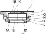
- the difference from Embodiment 1 is that: the lower end of the upper duct 1F and the upper end of the lower duct 1J realize the positioning and matching of each other by forming a positioning and matching platform 1H that fits up and down.
- the positioning and matching platform 1H is cylindrical
- the lower end of the upper duct 1F includes a stepped round platform
- the upper end of the lower duct 1J includes a matching stepped round platform, together forming a positioning and matching platform 1H.
- the contact surfaces of the upper duct 1F and the lower duct 1J are two upper and lower horizontal planes and the vertical plane in the middle of the horizontal planes, an upper heat insulation pad 1G is disposed between two upper horizontal planes, and a lower heat insulation pad 1I is disposed between the two lower horizontal planes.
- the air-mixing cavity 1D of the cigarette introduction pipe 1 is not provided with a first air-guiding duct 1M and a second air-guiding duct 1N.
Landscapes
- Cigarettes, Filters, And Manufacturing Of Filters (AREA)
Description
- The present invention relates to the field of novel cigarette smoking utensil, and in particular, to a smoke generating device with enhanced heat exchange effect.
- Existing heating cigarettes consist of two parts: a tobacco section and a filter rod. Most of filter rods are composed of a supporting section close to the tobacco section, a cooling section in the middle, and the end that is in contact with the consumer's lips. When the heating cigarette is inserted into the existing smoke generating device to heat the cigarette, as the tobacco section of the cigarette is relatively short, most of which is only 10~15mm, with the maximum no more than 20mm. Most cigarettes need to be inserted the smoke generating device together with the tobacco section and/or the supporting section of the filter rod into the heating cavity. Besides, in case consumers use general-purpose smoking utensils that are not produced for a certain variety (or brand) of cigarettes, the end of the heating element may be less than 2mm away from the supporting section of the cigarette filter rod, or even penetrating into the head of the supporting section of the filter rod. Under the above circumstances, once the cigarette is normally heated and smoked, there is a high probability that the supporting-section material cannot withstand the high temperature of the heating body with the occurrence of heat shrinkage or collapse. This not only affects the smoking of the second half of the cigarette (the cigarette deforms or softens due to heat shrinkage or collapse of the supporting section), but also directly affects the smoking taste of the cigarette.
- Smoke generating device with induction heating in a folded airway (Application No.
CN202011044385.3 - The present invention further improves on the basis of the above-mentioned patent (Application No.:
CN202011044385.3 CN111436662 A is directed to an electric heating smoking set with a circulating cooling airflow channel comprising an upper cover, a circumferential heating element surrounding a cigarette containing cavity, a heat insulation pipe, an inner support, a cleaning cover, an upper fixing piece and a shell. - The present invention only improves the
cigarette introduction pipe 1 of the smoking utensil in the above-mentioned patent (Application No.:CN202011044385.3 CN202011044385.3 - The present invention provides a smoke generating device with enhanced heat exchange effect. The smoke generating device includes: a
cigarette introduction pipe 1; - Wherein, the
cigarette introduction pipe 1 is disposed at the upper end of the smoke generating device, with a hollow tubular structure, its internal cavity is an air-mixing cavity 1D, the center of the upper end of thecigarette introduction pipe 1 is thefirst introduction hole 1B, and the center of its lower end is thesecond introduction hole 1E, the outer ring of thefirst introduction hole 1B is provided with a plurality of air-guidinggrooves 1C, the diameter of the air-mixing cavity 1D is greater than that of thefirst introduction hole 1B, thesecond introduction hole 1E and thefirst introduction hole 1B have the same diameter and are co-axial, the lower end of thecigarette introduction pipe 1 has at least oneair inlet channel 1A; - Wherein, the
cigarette introduction pipe 1 is divided into anupper duct 1F and alower duct 1J, and at least one heat insulation pad is disposed between theupper duct 1F and thelower duct 1J. - Preferably, the
upper duct 1F and thelower duct 1J are detachably connected or fixed by an adhesive. - Preferably, the lower end of the
upper duct 1F and the upper end of thelower duct 1J have/form a positioning and matchingplatform 1H fitting up and down to realize the positioning and matching of the two ducts, the positioning and matchingplatform 1H is conical or cylindrical. - Preferably, the groove or gap between the lower end of the upper duct I F and the
lower duct 1J is provided with a heat insulation pad, and the heat insulation pad itself is not filled with the groove or gap. - The lower end of the
upper duct 1F and the upper end of thelower duct 1J realize positioning and matching of each other through the positioning and matchingplatform 1H that fits up and down, or a part of the lower end of theupper duct 1F and a part of the upper end of thelower duct 1J together form a positioning and matchingplatform 1H. - Purposes of using heat insulation pad: performing relative heat insulation treatment on the
upper duct 1F and thelower duct 1J, so that the heat of induction heating from thelower duct 1J is more concentrated on thelower duct 1J, only a relatively small part can be transferred to theupper duct 1F through the positioning and matchingplatform 1H and the heat insulation pad with relatively large heat resistance; thus, the temperature at which the upper duct IF is slightly lower than that of thelower duct 1J. Whereas thefirst introduction hole 1B on theupper duct 1F is only a part of the circular ring, and the circumference of the contact part of theupper duct 1F with the cigarette does not include the arc length corresponding to the multiple air-guidinggroove 1C for air inlet, thus, there are fewer arcs in direct contact with the supporting section of the cigarette filter rod, which can reduce the heat transmitting from the lower part of the smoking utensil, thereby obviously improving heat shrinkage of the supporting section of the filter rod. - Preferably, the air-
mixing cavity 1D of thecigarette introduction pipe 1 is further provided with a first air-guidingduct 1M and a second air-guidingduct 1N; - Wherein, the heights of the first air-guiding
duct 1M and the second air-guidingduct 1N are smaller than the minimum height of the air-mixing cavity 1D, the inner diameters of the first air-guidingduct 1M and the second air-guidingduct 1N are smaller than the minimum diameter of the air-mixing cavity 1D, the axes of the two ducts are coincident with or in parallel with the axe of the air-mixing cavity 1D, the upper end of the first air-guidingduct 1M abuts against the inner wall of the upper end of thecigarette introduction pipe 1, the lower end of the second air-guidingduct 1N abuts against the inner wall of the lower end of thecigarette introduction pipe 1; - The second air-guiding
duct 1N is disposed inside theair inlet channel 1A and surrounds the periphery of the first air-guidingduct 1M, and the gap between the first air-guidingduct 1M and the second air-guidingduct 1N serves as an airflow channel. - Preferably, the first air-guiding
duct 1M or the second air-guidingduct 1N are integrally or detachably connected to thecigarette introduction pipe 1. - Preferably, the
cigarette introduction pipe 1 is also provided with a fixing part for fixing the first air-guidingduct 1M and the second air-guidingduct 1N. - Preferably, the fixing part that fixes the first air-guiding
duct 1M and the second air-guidingduct 1N is at least one upperinner protrusion 1Q and at least one lowerinner protrusion 1P provided on the inner wall of thecigarette introduction pipe 1; - Wherein, the upper
inner protrusion 1Q is integrally connected to the inner wall of the upper end of thecigarette introduction pipe 1, and protrudes downward into the air-mixing cavity 1D relative to the inner wall; - The lower
inner protrusion 1P is disposed on the inner side of theair inlet channel 1A, which is integrally connected to the inner wall of the lower end of thecigarette introduction pipe 1, and protrudes upward into the air-mixing cavity 1D relative to the inner wall; the first air-guidingduct 1M abuts against the side wall of the upperinner protrusion 1Q and is restricted to its inner side; the second air-guidingduct 1N abuts against the side wall of the lowerinner protrusion 1P and is restricted to its outer side. - The "periphery" and "outer side" in the present disclosure refers to the direction away from the central axis of the heating cup of the smoke generating device.
- The "inner" of "inner side" in the present disclosure refers to the direction close to the central axis of the heating cup of the smoke generating device.
- Preferably, the upper
inner protrusion 1Q and the lowerinner protrusion 1P are point-shaped or ring-shaped. - The circulation path and heat-exchange process of outside air in the air-mixing
cavity 1D are as follows:
In case the cigarette is inserted into the smoke generating device for smoking, the outside air enters the gap between the outer wall of the cigarette and the air-guidinggroove 1C distributed in the circumferential direction of thefirst introduction hole 1B, while entering the bottom of the air-mixing cavity 1D, the outside air at room-temperature relatively cools down the outer wall of the heated and sucked cigarette filter rod of the smoke generating device. The air enters the gap between the first air-guidingduct 1M and the second air-guidingduct 1N through the airflow channel between the lower end of the first air-guidingduct 1M and the air-mixing cavity 1D, flowing upward to the airflow channel between the upper end of the second air-guidingduct 1N and the air-mixing cavity 1D, and entering theair inlet channel 1A downwards through the airflow channel between the outer wall of the second air-guidingduct 1N and the inner wall of the air-mixingcavity 1D. - During this process, the airflow is folded back in the air-
mixing cavity 1D many times, and the heat conducted from the inside of the smoke generating device exchanges with the air at room-temperature flowing through the air-mixing cavity 1D through theupper duct 1F and thelower duct 1J, until the passing air, under the negative pressure of smokers' suction, finally sends the preliminarily heated air (through the airflow channel where the heating element 6 is located) into the cigarette accommodating cavity through theair inlet channel 1A. - Meanwhile, the first air-guiding
duct 1M and the second air-guidingduct 1N may also obtain maximum heat through radiation of thecigarette introduction pipe 1 and the heating element 6 in contact with them, when the circulated air passes around the first air-guidingduct 1M and the second air-guidingduct 1N, the air is also heated. - Another solution of the present invention is: the second air-guiding
duct 1N is replaced with a plurality of annularly distributedair inlet needles 1L inserted into theair inlet channel 1A in an interference fit manner. - The present invention has the following beneficial effects:
- 1. The present invention designs a smoke generating device with enhanced heat exchange effect, and the cigarette introduction pipe is designed as two separable parts - the upper and lower duct, the heat insulation pad performs relative heat insulation on the upper duct and the lower duct, further playing the role of reducing the heat transmitting from the lower heating cup and heating element to the upper part. Thus, the temperature of the upper duct in contact with the cigarette filter rod is lower, which greatly reduces heat shrinkage or collapse caused by the material of the supporting section of the cigarette filter rod in contact with the cigarette introduction pipe of the smoke generating device that cannot withstand high temperature of the heating body.
- 2. In the preferred technical solutions, the present invention designs the first air-guiding
duct 1M and the second air-guidingduct 1N that guide air circulation inside the cigarette introduction pipe, the air can go back and forth many times in the air-mixing chamber 1D to fully exchange heat. The outside air cools down the cigarette introduction pipe, while the cigarette introduction pipe and the heating element preheat the air. -
-
FIG.1 is a schematic longitudinal cross-sectional view of thecigarette introduction pipe 1 ofEmbodiment 1. FIG.1a shows the condition in which cigarettes are not inserted, while FIG.1b shows the part of the inserted cigarette with a dotted line. -
FIG.2 is a schematic longitudinal cross-sectional view of the smoke generating device ofEmbodiment 1 after inserting a cigarette. -
FIG.3 is a schematic longitudinal cross-sectional view of thecigarette introduction pipe 1 of Embodiment 2. FIG.3a shows the condition in which cigarettes are not inserted, while FIG.3b shows the part of the inserted cigarette with a dotted line. -
FIG.4 is a schematic longitudinal cross-sectional view of thecigarette introduction pipe 1 of Embodiment 3. - List of signs in the drawings:
1. Cigarette introduction pipe, 1A. Air inlet channel, 1B. First introduction hole, 1C. Air-guiding groove, 1D. Air-mixing cavity, 1E. Second introduction hole, 1F. Upper duct, 1G Upper heat insulation pad, 1H. Positioning and matching platform, 1I. Lower heat insulation pad, 1J. Lower duct, 1K. Integrated duct, 1L. Air inlet needle, 1M. First air-guiding duct, 1N. Second air-guiding duct, 1P. Lower inner protrusion, 1Q, Upper inner protrusion, - The present disclosure will be further explained below through specific embodiments.
- As shown in
FIG 1 , a smoke generating device with enhanced heat exchange effect, the smoke generating device includes: acigarette introduction pipe 1; other parts of the smoking utensil are the same as those in the patent (Application No.2020110443853); - Wherein, the
cigarette introduction pipe 1 is disposed at the upper end of the smoke generating device, with a hollow tubular structure, its internal cavity is an air-mixingcavity 1D, the center of the upper end of thecigarette introduction pipe 1 is thefirst introduction hole 1B, and the center of its lower end is thesecond introduction hole 1E, the outer ring of thefirst introduction hole 1B is provided with a plurality of air-guidinggrooves 1C, the diameter of the air-mixingcavity 1D is greater than that of thefirst introduction hole 1B, thesecond introduction hole 1E and thefirst introduction hole 1B have the same diameter and are co-axial, the lower end of thecigarette introduction pipe 1 has at least oneair inlet channel 1A; - Wherein, the
cigarette introduction pipe 1 is divided into anupper duct 1F and alower duct 1J, and at least one heat insulation pad is disposed between theupper duct 1F and thelower duct 1J. - The diameter of the
first introduction hole 1B is equal to that of the cigarette accommodating cavity, both are slightly larger than the outer diameter of the inserted cigarette. - In the embodiment, the lower end of the
upper duct 1F and the upper end of thelower duct 1J realize the positioning and matching of each other by forming a positioning andmatching platform 1H that fits up and down. The positioning andmatching platform 1H is cone-shaped, which can be fixed by the self-locking and positioning function of the cone. The positioning andmatching platform 1H is formed by a conical part at the lower end of theupper duct 1F and a conical part at the upper end of thelower duct 1J. The contact surfaces of theupper duct 1F and thelower duct 1J are two horizontal planes at the upper and lower part and a slope surface in the middle of the two horizontal planes, an upperheat insulation pad 1G is disposed between the two upper horizontal planes, and a lowerheat insulation pad 1I is disposed between the two lower horizontal planes. Both the upperheat insulation pad 1G and the lowerheat insulation pad 1I are made of silica gel with high-temperature resistance and good heat insulation performance. - Of course, in other embodiments, the contact surface between the upper air-guiding
duct 1F and the lower air-guidingduct 1J may also have other forms, as long as the above functions can be realized. - The air-mixing
cavity 1D of thecigarette introduction pipe 1 is further provided with a first air-guidingduct 1M and a second air-guidingduct 1N;
Wherein, the heights of the first air-guidingduct 1M and the second air-guidingduct 1N are smaller than the minimum height of the air-mixingcavity 1D, the inner diameters of the first air-guidingduct 1M and the second air-guidingduct 1N are smaller than the minimum diameter of the air-mixingcavity 1D, the axes of the two ducts are in parallel with the axe of the air-mixingcavity 1D, the upper end of the first air-guidingduct 1M abuts against the inner wall of the upper end of thecigarette introduction pipe 1, the lower end of the second air-guidingduct 1N abuts against the inner wall of the lower end of thecigarette introduction pipe 1; the second air-guidingduct 1N is disposed inside theair inlet channel 1A and surrounds the periphery of the first air-guidingduct 1M, the gap between the first air-guidingduct 1M and the second air-guidingduct 1N serves as an airflow channel. - The first air-guiding
duct 1M, the second air-guidingduct 1N are separate from thecigarette introduction pipe 1. - The
cigarette introduction pipe 1 is also provided with an upperinner protrusion 1Q and a lowerinner protrusion 1P inside to fix the position of the first air-guidingduct 1M and the second air-guidingduct 1N; - Wherein, the upper inner protrusion (1Q) is a ring-shaped boss, which is connected to the inner wall of the upper end of the
cigarette introduction pipe 1, and protrudes downward into the air-mixingcavity 1D relative to the inner wall; - The lower
inner protrusion 1P is a ring-shaped boss, which is disposed on the inner side of theair inlet channel 1A and connected to the inner wall of the lower end of thecigarette introduction pipe 1, it protrudes upward into the air-mixingcavity 1D relative to the inner wall; the first air-guidingduct 1M abuts against the side wall of the upperinner protrusion 1Q and is restricted to its inner side; the second air-guidingduct 1N abuts against the side wall of the lowerinner protrusion 1P and is restricted to its outer side. - The lower end of the first air-guiding
duct 1M is opposite to the lowerinner protrusion 1P, with the gap therebetween serves as an airflow channel. The upper end of the second air-guidingduct 1N is opposite to the upperinner protrusion 1Q, with the gap therebetween serves as an airflow channel. The gap between the outer wall of the second air-guidingduct 1N and the inner side of the air-mixingcavity 1D serves as an airflow channel. - The circulation path and heat-exchange process of outside air in the air-mixing
cavity 1D are as follows:
In case the cigarette is inserted into the smoke generating device for smoking, the outside air enters the gap between the outer wall of the cigarette and the air-guidinggroove 1C distributed in the circumferential direction of thefirst introduction hole 1B, while entering the bottom of the air-mixingcavity 1D, the outside air at room-temperature relatively cools down the outer wall of the heated and sucked cigarette filter rod of the smoke generating device. The air enters the gap between the first air-guidingduct 1M and the second air-guidingduct 1N through the airflow channel between the lower end of the first air-guidingduct 1M and the air-mixingcavity 1D, flowing upward to the airflow channel between the upper end of the second air-guidingduct 1N and the air-mixingcavity 1D, and entering theair inlet channel 1A downwards through the airflow channel between the outer wall of the second air-guidingduct 1N and the inner wall of the air-mixingcavity 1D. - During this process, the airflow is folded back in the air-mixing
cavity 1D many times, and the heat conducted from the inside of the smoke generating device exchanges with the air at room-temperature flowing through the air-mixingcavity 1D through theupper duct 1F and thelower duct 1J, until the passing air, under the negative pressure of smokers' suction, finally sends the preliminarily heated air (through the airflow channel where the heating element is located) into the cigarette accommodating cavity through theair inlet channel 1A. Meanwhile, the first air-guidingduct 1M and the second air-guidingduct 1N may also obtain maximum heat through radiation of thecigarette introduction pipe 1 and the heating element 6 in contact with them, when the circulated air passes around the first air-guidingduct 1M and the second air-guidingduct 1N, the air is also heated. - FIG.1a is a schematic view of a
cigarette introduction pipe 1. FIG. 1b is a schematic view of thecigarette introduction pipe 1 after inserting cigarettes. -
FIG.2 is a schematic view after inserting cigarettes in the smoke generating device inEmbodiment 1. -
FIG.2 shows the positions of each part of the cigarette, the suction of airflow, and the direction of the airflow. - A smoke generating device with enhanced heat exchange effect. The smoke generating device includes: a
cigarette introduction pipe 1. - As shown in
FIG.3 , the difference between Embodiment 2 andEmbodiment 1 is that: the second air-guidingduct 1N is replaced with a plurality of annularly distributedair inlet needle 1L inserted into theair inlet channel 1A in an interference fit manner. - The diameter of the inner hole of the
air inlet needle 1L is 0.1-0.9mm. - The first air-guiding
duct 1M can be replaced with: anintegrated duct 1K integrally connected to thecigarette introduction pipe 1. The inner diameter of theintegrated duct 1K is equal to the diameter of thefirst introduction hole 1B. Theintegrated duct 1K is thin-walled. - FIG.3a is a schematic view of a
cigarette introduction pipe 1. FIG.3b is a schematic view of thecigarette introduction pipe 1 after inserting cigarettes. - A smoke generating device with enhanced heat exchange effect. The smoke generating device includes: a
cigarette introduction pipe 1. - As shown in
FIG.4 , the difference fromEmbodiment 1 is that:
the lower end of theupper duct 1F and the upper end of thelower duct 1J realize the positioning and matching of each other by forming a positioning andmatching platform 1H that fits up and down. - In case the positioning and
matching platform 1H is cylindrical, the lower end of theupper duct 1F includes a stepped round platform, the upper end of thelower duct 1J includes a matching stepped round platform, together forming a positioning andmatching platform 1H. - The contact surfaces of the
upper duct 1F and thelower duct 1J are two upper and lower horizontal planes and the vertical plane in the middle of the horizontal planes, an upperheat insulation pad 1G is disposed between two upper horizontal planes, and a lowerheat insulation pad 1I is disposed between the two lower horizontal planes. - The air-mixing
cavity 1D of thecigarette introduction pipe 1 is not provided with a first air-guidingduct 1M and a second air-guidingduct 1N. - The protection scope of the present invention shall be subject to the protection scope of the claims.
Claims (10)
- A smoke generating device with enhanced heat exchange effect, comprising a cigarette introduction pipe (1);Wherein, the cigarette introduction pipe (1) is disposed at an upper end of the smoke generating device, with a hollow tubular structure, an internal cavity is an air-mixing cavity (1D), the center of the upper end of the cigarette introduction pipe (1) is a first introduction hole (1B), and the center of its lower end is a second introduction hole (lE), an outer ring of the first introduction hole (1B) is provided with a plurality of air-guiding grooves (1C), the diameter of the air-mixing cavity (1D) is greater than that of the first introduction hole (1B), the second introduction hole (1E) and the first introduction hole (1B) have the same diameter and are co-axial, a lower end of the cigarette introduction pipe (1) has at least one air inlet channel (1A);wherein, the cigarette introduction pipe (1) is divided into an upper duct (1F) and a lower duct (1J), and at least one heat insulation pad is disposed between the upper duct (1F) and the lower duct (11).
- The smoke generating device of claim 1, wherein the upper duct (1F) and the lower duct (1J) are detachably connected or fixed by an adhesive.
- The smoke generating device of claim 1, wherein the lower end of the upper duct (1F) and the upper end of the lower duct (I J) have/form a positioning and matching platform (1H) fitting up and down to realize the positioning and matching of the two ducts, the positioning and matching platform (1H) is conical or cylindrical.
- The smoke generating device of claim 1, wherein a groove or gap between the lower end of the upper duct (1F) and the lower duct (1J) is provided with a heat insulation pad, and the heat insulation pad itself is not filled with the groove or gap.
- The smoke generating device of claim 1, wherein the air-mixing cavity (1D) of the cigarette introduction pipe (1) is also provided with a first air-guiding duct (1M) and a second air-guiding duct (1N);wherein, a heights of the first air-guiding duct (1M) and the second air-guiding duct (1N) are smaller than a minimum height of the air-mixing cavity (1D), an inner diameters of the first air-guiding duct (1M) and the second air-guiding duct (1N) are smaller than a smallest diameter of the air-mixing cavity (1D), the axes of the two air-guiding ducts coincide with the axe of the air-mixing cavity (1D) or are disposed in parallel, an upper end of the first air-guiding duct (1M) abuts against an inner wall of the upper end of the cigarette introduction pipe (1), and the lower end of the second air-guiding duct (1N) abuts against an inner wall of the lower end of the cigarette introduction pipe (1);The second air-guiding duct (1N) is disposed inside an air inlet channel (1A) and surrounds the periphery of the first air-guiding duct (1M), a gap between the first air-guiding duct (1M) and the second air-guiding duct (1N) serves as an airflow channel.
- The smoke generating device of claim 5, wherein the first air-guiding duct (1M) or the second air-guiding duct (1N) are integrally or detachably connected to the cigarette introduction pipe (1).
- The smoke generating device of claim 5, wherein the cigarette introduction pipe (1) is also provided with a fixing part for fixing the first air-guiding duct (1M) and the second air-guiding duct (1N).
- The smoke generating device of claim 7, wherein the fixing part that fixes the first air-guiding duct (1M) and the second air-guiding duct (1N) is at least one upper inner protrusion (1Q) and at least one lower inner protrusion (1P) provided on the inner wall of the cigarette introduction pipe (1);Wherein, the upper inner protrusion (1Q) is integrally connected with the inner wall of the upper end of the cigarette introduction pipe (1), and protrudes downward into the air-mixing cavity (1D) relative to the inner wall;The lower inner protrusion (1P) is disposed on the inner side of the air inlet channel (1A), which is integrally connected to the inner wall of the lower end of the cigarette introduction pipe (1), and protrudes upward into the air-mixing cavity (1D) relative to the inner wall; the first air-guiding duct (1M) abuts against the side wall of the upper inner protrusion (1Q) and is restricted to its inner side; the second air-guiding duct (1N) abuts against the side wall of the lower inner protrusion (1P) and is restricted to its outer side.
- The smoke generating device of claim 5, wherein the second air-guiding duct (1N) is replaced with a plurality of annularly distributed air inlet needles (1L) inserted into the air inlet channel (1A) in an interference fit manner.
- The smoke generating device of claim 8, wherein the upper inner protrusion (1Q) and the lower inner protrusion (1P) are point-shaped or ring-shaped.
Applications Claiming Priority (1)
| Application Number | Priority Date | Filing Date | Title |
|---|---|---|---|
| PCT/CN2020/118752 WO2021189801A1 (en) | 2020-09-29 | 2020-09-29 | Smoking apparatus for enhancing heat exchange effect |
Publications (3)
| Publication Number | Publication Date |
|---|---|
| EP3942949A1 EP3942949A1 (en) | 2022-01-26 |
| EP3942949A4 EP3942949A4 (en) | 2022-06-01 |
| EP3942949B1 true EP3942949B1 (en) | 2023-04-12 |
Family
ID=77890899
Family Applications (1)
| Application Number | Title | Priority Date | Filing Date |
|---|---|---|---|
| EP20927028.9A Active EP3942949B1 (en) | 2020-09-29 | 2020-09-29 | Smoking apparatus for enhancing heat exchange effect |
Country Status (2)
| Country | Link |
|---|---|
| EP (1) | EP3942949B1 (en) |
| WO (1) | WO2021189801A1 (en) |
Families Citing this family (1)
| Publication number | Priority date | Publication date | Assignee | Title |
|---|---|---|---|---|
| CN112120292B (en) * | 2020-09-29 | 2024-11-29 | 云南中烟工业有限责任公司 | Fuming device for enhancing heat exchange effect |
Family Cites Families (6)
| Publication number | Priority date | Publication date | Assignee | Title |
|---|---|---|---|---|
| CN107772540B (en) * | 2016-08-29 | 2021-11-02 | 卓尔悦欧洲控股有限公司 | Flue-cured tobacco electronic cigarette and its cigarette pot structure |
| CN206923683U (en) * | 2017-06-02 | 2018-01-26 | 湖南中烟工业有限责任公司 | low temperature smoking set |
| CN208144423U (en) * | 2018-02-26 | 2018-11-27 | 常州市派腾电子技术服务有限公司 | Flue-cured tobacco heating member, pipe bowl device and electronic cigarette |
| US10706900B2 (en) | 2018-11-01 | 2020-07-07 | Intel Corporation | Data and clock synchronization and variation compensation apparatus and method |
| CN111436662B (en) * | 2020-04-30 | 2024-07-09 | 云南中烟工业有限责任公司 | Smoking article with circulating cooling airway, smoking system including the same and use method |
| CN111449302B (en) * | 2020-05-12 | 2024-08-13 | 深圳市长能汇科科技有限公司 | Heat-insulating non-contact type electronic cigarette heating device and use method thereof |
-
2020
- 2020-09-29 EP EP20927028.9A patent/EP3942949B1/en active Active
- 2020-09-29 WO PCT/CN2020/118752 patent/WO2021189801A1/en not_active Ceased
Also Published As
| Publication number | Publication date |
|---|---|
| EP3942949A4 (en) | 2022-06-01 |
| WO2021189801A1 (en) | 2021-09-30 |
| EP3942949A1 (en) | 2022-01-26 |
Similar Documents
| Publication | Publication Date | Title |
|---|---|---|
| US10159285B2 (en) | Vaporizer with improved ventilation | |
| CN109315840B (en) | Ceramic heating element and atomizer composed of same | |
| EP4000433B1 (en) | Smoke generating device for induction heating in folding air channel | |
| EP3162226B1 (en) | Electronic cigarette | |
| CN104068476B (en) | Heating assembly for electronic cigarette | |
| CN109640717A (en) | Apparatus for aerosol creation | |
| US20140283858A1 (en) | Electronic cigarette | |
| EP3932231B1 (en) | Smoking apparatus for induction heating at front end of cigarette | |
| CN109123807B (en) | Electric heating device | |
| CN105768227B (en) | Electronic cigarette core and electronic cigarette atomizer | |
| WO2016154797A1 (en) | Atomizer | |
| CN108542009B (en) | Composite base rod for heating incombustible cigarettes and heating incombustible cigarettes | |
| WO2020258384A1 (en) | Cigarette heating device | |
| CN113662266B (en) | An outer cigarette cup locking type electric heating smoking set, electric heating component and use method thereof | |
| CN105192894A (en) | Electronic cigarette atomizer heating device, electronic cigarette atomizer head and electronic cigarette thereof | |
| CN109832662B (en) | Cigarette capable of not burning by heating | |
| EP3942949A1 (en) | Smoking apparatus for enhancing heat exchange effect | |
| CN213663674U (en) | A smoking device with enhanced heat exchange effect | |
| CN112120292B (en) | Fuming device for enhancing heat exchange effect | |
| JP3220624U (en) | Non-combustion heating type smoking device and heating assembly thereof | |
| CN109770422B (en) | A method for manufacturing a cooling composite filter rod | |
| CN111449302B (en) | Heat-insulating non-contact type electronic cigarette heating device and use method thereof | |
| CN212414752U (en) | Fuming device for induction heating at front end of cigarette | |
| CN208941055U (en) | an electric heating appliance | |
| CN215189418U (en) | Centrally heated smoking set with auxiliary heating and cooling |
Legal Events
| Date | Code | Title | Description |
|---|---|---|---|
| STAA | Information on the status of an ep patent application or granted ep patent |
Free format text: STATUS: THE INTERNATIONAL PUBLICATION HAS BEEN MADE |
|
| PUAI | Public reference made under article 153(3) epc to a published international application that has entered the european phase |
Free format text: ORIGINAL CODE: 0009012 |
|
| STAA | Information on the status of an ep patent application or granted ep patent |
Free format text: STATUS: REQUEST FOR EXAMINATION WAS MADE |
|
| 17P | Request for examination filed |
Effective date: 20211022 |
|
| AK | Designated contracting states |
Kind code of ref document: A1 Designated state(s): AL AT BE BG CH CY CZ DE DK EE ES FI FR GB GR HR HU IE IS IT LI LT LU LV MC MK MT NL NO PL PT RO RS SE SI SK SM TR |
|
| STAA | Information on the status of an ep patent application or granted ep patent |
Free format text: STATUS: EXAMINATION IS IN PROGRESS |
|
| A4 | Supplementary search report drawn up and despatched |
Effective date: 20220504 |
|
| RIC1 | Information provided on ipc code assigned before grant |
Ipc: A24F 40/40 20200101AFI20220428BHEP |
|
| 17Q | First examination report despatched |
Effective date: 20220516 |
|
| REG | Reference to a national code |
Ref country code: DE Ref legal event code: R079 Free format text: PREVIOUS MAIN CLASS: A24F0040400000 Ipc: A24F0040480000 Ref document number: 602020009762 Country of ref document: DE |
|
| RIC1 | Information provided on ipc code assigned before grant |
Ipc: A24F 40/20 20200101ALN20221004BHEP Ipc: A24F 40/48 20200101AFI20221004BHEP |
|
| GRAP | Despatch of communication of intention to grant a patent |
Free format text: ORIGINAL CODE: EPIDOSNIGR1 |
|
| STAA | Information on the status of an ep patent application or granted ep patent |
Free format text: STATUS: GRANT OF PATENT IS INTENDED |
|
| RIC1 | Information provided on ipc code assigned before grant |
Ipc: A24F 40/20 20200101ALN20221028BHEP Ipc: A24F 40/48 20200101AFI20221028BHEP |
|
| INTG | Intention to grant announced |
Effective date: 20221129 |
|
| GRAS | Grant fee paid |
Free format text: ORIGINAL CODE: EPIDOSNIGR3 |
|
| GRAA | (expected) grant |
Free format text: ORIGINAL CODE: 0009210 |
|
| STAA | Information on the status of an ep patent application or granted ep patent |
Free format text: STATUS: THE PATENT HAS BEEN GRANTED |
|
| DAV | Request for validation of the european patent (deleted) | ||
| DAX | Request for extension of the european patent (deleted) | ||
| AK | Designated contracting states |
Kind code of ref document: B1 Designated state(s): AL AT BE BG CH CY CZ DE DK EE ES FI FR GB GR HR HU IE IS IT LI LT LU LV MC MK MT NL NO PL PT RO RS SE SI SK SM TR |
|
| REG | Reference to a national code |
Ref country code: GB Ref legal event code: FG4D |
|
| REG | Reference to a national code |
Ref country code: CH Ref legal event code: EP |
|
| REG | Reference to a national code |
Ref country code: DE Ref legal event code: R096 Ref document number: 602020009762 Country of ref document: DE |
|
| REG | Reference to a national code |
Ref country code: IE Ref legal event code: FG4D |
|
| REG | Reference to a national code |
Ref country code: AT Ref legal event code: REF Ref document number: 1559313 Country of ref document: AT Kind code of ref document: T Effective date: 20230515 |
|
| REG | Reference to a national code |
Ref country code: LT Ref legal event code: MG9D |
|
| REG | Reference to a national code |
Ref country code: NL Ref legal event code: MP Effective date: 20230412 |
|
| REG | Reference to a national code |
Ref country code: AT Ref legal event code: MK05 Ref document number: 1559313 Country of ref document: AT Kind code of ref document: T Effective date: 20230412 |
|
| PG25 | Lapsed in a contracting state [announced via postgrant information from national office to epo] |
Ref country code: NL Free format text: LAPSE BECAUSE OF FAILURE TO SUBMIT A TRANSLATION OF THE DESCRIPTION OR TO PAY THE FEE WITHIN THE PRESCRIBED TIME-LIMIT Effective date: 20230412 |
|
| PG25 | Lapsed in a contracting state [announced via postgrant information from national office to epo] |
Ref country code: SE Free format text: LAPSE BECAUSE OF FAILURE TO SUBMIT A TRANSLATION OF THE DESCRIPTION OR TO PAY THE FEE WITHIN THE PRESCRIBED TIME-LIMIT Effective date: 20230412 Ref country code: PT Free format text: LAPSE BECAUSE OF FAILURE TO SUBMIT A TRANSLATION OF THE DESCRIPTION OR TO PAY THE FEE WITHIN THE PRESCRIBED TIME-LIMIT Effective date: 20230814 Ref country code: NO Free format text: LAPSE BECAUSE OF FAILURE TO SUBMIT A TRANSLATION OF THE DESCRIPTION OR TO PAY THE FEE WITHIN THE PRESCRIBED TIME-LIMIT Effective date: 20230712 Ref country code: ES Free format text: LAPSE BECAUSE OF FAILURE TO SUBMIT A TRANSLATION OF THE DESCRIPTION OR TO PAY THE FEE WITHIN THE PRESCRIBED TIME-LIMIT Effective date: 20230412 Ref country code: AT Free format text: LAPSE BECAUSE OF FAILURE TO SUBMIT A TRANSLATION OF THE DESCRIPTION OR TO PAY THE FEE WITHIN THE PRESCRIBED TIME-LIMIT Effective date: 20230412 |
|
| PG25 | Lapsed in a contracting state [announced via postgrant information from national office to epo] |
Ref country code: RS Free format text: LAPSE BECAUSE OF FAILURE TO SUBMIT A TRANSLATION OF THE DESCRIPTION OR TO PAY THE FEE WITHIN THE PRESCRIBED TIME-LIMIT Effective date: 20230412 Ref country code: PL Free format text: LAPSE BECAUSE OF FAILURE TO SUBMIT A TRANSLATION OF THE DESCRIPTION OR TO PAY THE FEE WITHIN THE PRESCRIBED TIME-LIMIT Effective date: 20230412 Ref country code: LV Free format text: LAPSE BECAUSE OF FAILURE TO SUBMIT A TRANSLATION OF THE DESCRIPTION OR TO PAY THE FEE WITHIN THE PRESCRIBED TIME-LIMIT Effective date: 20230412 Ref country code: LT Free format text: LAPSE BECAUSE OF FAILURE TO SUBMIT A TRANSLATION OF THE DESCRIPTION OR TO PAY THE FEE WITHIN THE PRESCRIBED TIME-LIMIT Effective date: 20230412 Ref country code: IS Free format text: LAPSE BECAUSE OF FAILURE TO SUBMIT A TRANSLATION OF THE DESCRIPTION OR TO PAY THE FEE WITHIN THE PRESCRIBED TIME-LIMIT Effective date: 20230812 Ref country code: HR Free format text: LAPSE BECAUSE OF FAILURE TO SUBMIT A TRANSLATION OF THE DESCRIPTION OR TO PAY THE FEE WITHIN THE PRESCRIBED TIME-LIMIT Effective date: 20230412 Ref country code: GR Free format text: LAPSE BECAUSE OF FAILURE TO SUBMIT A TRANSLATION OF THE DESCRIPTION OR TO PAY THE FEE WITHIN THE PRESCRIBED TIME-LIMIT Effective date: 20230713 Ref country code: AL Free format text: LAPSE BECAUSE OF FAILURE TO SUBMIT A TRANSLATION OF THE DESCRIPTION OR TO PAY THE FEE WITHIN THE PRESCRIBED TIME-LIMIT Effective date: 20230412 |
|
| PG25 | Lapsed in a contracting state [announced via postgrant information from national office to epo] |
Ref country code: FI Free format text: LAPSE BECAUSE OF FAILURE TO SUBMIT A TRANSLATION OF THE DESCRIPTION OR TO PAY THE FEE WITHIN THE PRESCRIBED TIME-LIMIT Effective date: 20230412 |
|
| REG | Reference to a national code |
Ref country code: DE Ref legal event code: R097 Ref document number: 602020009762 Country of ref document: DE |
|
| PG25 | Lapsed in a contracting state [announced via postgrant information from national office to epo] |
Ref country code: SK Free format text: LAPSE BECAUSE OF FAILURE TO SUBMIT A TRANSLATION OF THE DESCRIPTION OR TO PAY THE FEE WITHIN THE PRESCRIBED TIME-LIMIT Effective date: 20230412 |
|
| PG25 | Lapsed in a contracting state [announced via postgrant information from national office to epo] |
Ref country code: SM Free format text: LAPSE BECAUSE OF FAILURE TO SUBMIT A TRANSLATION OF THE DESCRIPTION OR TO PAY THE FEE WITHIN THE PRESCRIBED TIME-LIMIT Effective date: 20230412 Ref country code: SK Free format text: LAPSE BECAUSE OF FAILURE TO SUBMIT A TRANSLATION OF THE DESCRIPTION OR TO PAY THE FEE WITHIN THE PRESCRIBED TIME-LIMIT Effective date: 20230412 Ref country code: RO Free format text: LAPSE BECAUSE OF FAILURE TO SUBMIT A TRANSLATION OF THE DESCRIPTION OR TO PAY THE FEE WITHIN THE PRESCRIBED TIME-LIMIT Effective date: 20230412 Ref country code: EE Free format text: LAPSE BECAUSE OF FAILURE TO SUBMIT A TRANSLATION OF THE DESCRIPTION OR TO PAY THE FEE WITHIN THE PRESCRIBED TIME-LIMIT Effective date: 20230412 Ref country code: DK Free format text: LAPSE BECAUSE OF FAILURE TO SUBMIT A TRANSLATION OF THE DESCRIPTION OR TO PAY THE FEE WITHIN THE PRESCRIBED TIME-LIMIT Effective date: 20230412 |
|
| PLBE | No opposition filed within time limit |
Free format text: ORIGINAL CODE: 0009261 |
|
| STAA | Information on the status of an ep patent application or granted ep patent |
Free format text: STATUS: NO OPPOSITION FILED WITHIN TIME LIMIT |
|
| 26N | No opposition filed |
Effective date: 20240115 |
|
| REG | Reference to a national code |
Ref country code: DE Ref legal event code: R119 Ref document number: 602020009762 Country of ref document: DE |
|
| REG | Reference to a national code |
Ref country code: CH Ref legal event code: PL |
|
| PG25 | Lapsed in a contracting state [announced via postgrant information from national office to epo] |
Ref country code: SI Free format text: LAPSE BECAUSE OF FAILURE TO SUBMIT A TRANSLATION OF THE DESCRIPTION OR TO PAY THE FEE WITHIN THE PRESCRIBED TIME-LIMIT Effective date: 20230412 |
|
| PG25 | Lapsed in a contracting state [announced via postgrant information from national office to epo] |
Ref country code: LU Free format text: LAPSE BECAUSE OF NON-PAYMENT OF DUE FEES Effective date: 20230929 |
|
| REG | Reference to a national code |
Ref country code: BE Ref legal event code: MM Effective date: 20230930 |
|
| PG25 | Lapsed in a contracting state [announced via postgrant information from national office to epo] |
Ref country code: SI Free format text: LAPSE BECAUSE OF FAILURE TO SUBMIT A TRANSLATION OF THE DESCRIPTION OR TO PAY THE FEE WITHIN THE PRESCRIBED TIME-LIMIT Effective date: 20230412 Ref country code: LU Free format text: LAPSE BECAUSE OF NON-PAYMENT OF DUE FEES Effective date: 20230929 Ref country code: MC Free format text: LAPSE BECAUSE OF FAILURE TO SUBMIT A TRANSLATION OF THE DESCRIPTION OR TO PAY THE FEE WITHIN THE PRESCRIBED TIME-LIMIT Effective date: 20230412 |
|
| REG | Reference to a national code |
Ref country code: IE Ref legal event code: MM4A |
|
| PG25 | Lapsed in a contracting state [announced via postgrant information from national office to epo] |
Ref country code: IE Free format text: LAPSE BECAUSE OF NON-PAYMENT OF DUE FEES Effective date: 20230929 |
|
| PG25 | Lapsed in a contracting state [announced via postgrant information from national office to epo] |
Ref country code: CH Free format text: LAPSE BECAUSE OF NON-PAYMENT OF DUE FEES Effective date: 20230930 |
|
| PG25 | Lapsed in a contracting state [announced via postgrant information from national office to epo] |
Ref country code: IE Free format text: LAPSE BECAUSE OF NON-PAYMENT OF DUE FEES Effective date: 20230929 Ref country code: FR Free format text: LAPSE BECAUSE OF NON-PAYMENT OF DUE FEES Effective date: 20230930 Ref country code: DE Free format text: LAPSE BECAUSE OF NON-PAYMENT OF DUE FEES Effective date: 20240403 Ref country code: CH Free format text: LAPSE BECAUSE OF NON-PAYMENT OF DUE FEES Effective date: 20230930 |
|
| PG25 | Lapsed in a contracting state [announced via postgrant information from national office to epo] |
Ref country code: BE Free format text: LAPSE BECAUSE OF NON-PAYMENT OF DUE FEES Effective date: 20230930 |
|
| PG25 | Lapsed in a contracting state [announced via postgrant information from national office to epo] |
Ref country code: BG Free format text: LAPSE BECAUSE OF FAILURE TO SUBMIT A TRANSLATION OF THE DESCRIPTION OR TO PAY THE FEE WITHIN THE PRESCRIBED TIME-LIMIT Effective date: 20230412 |
|
| PG25 | Lapsed in a contracting state [announced via postgrant information from national office to epo] |
Ref country code: BG Free format text: LAPSE BECAUSE OF FAILURE TO SUBMIT A TRANSLATION OF THE DESCRIPTION OR TO PAY THE FEE WITHIN THE PRESCRIBED TIME-LIMIT Effective date: 20230412 |
|
| GBPC | Gb: european patent ceased through non-payment of renewal fee |
Effective date: 20240929 |
|
| PG25 | Lapsed in a contracting state [announced via postgrant information from national office to epo] |
Ref country code: GB Free format text: LAPSE BECAUSE OF NON-PAYMENT OF DUE FEES Effective date: 20240929 |
|
| PG25 | Lapsed in a contracting state [announced via postgrant information from national office to epo] |
Ref country code: CY Free format text: LAPSE BECAUSE OF FAILURE TO SUBMIT A TRANSLATION OF THE DESCRIPTION OR TO PAY THE FEE WITHIN THE PRESCRIBED TIME-LIMIT; INVALID AB INITIO Effective date: 20200929 |
|
| PG25 | Lapsed in a contracting state [announced via postgrant information from national office to epo] |
Ref country code: HU Free format text: LAPSE BECAUSE OF FAILURE TO SUBMIT A TRANSLATION OF THE DESCRIPTION OR TO PAY THE FEE WITHIN THE PRESCRIBED TIME-LIMIT; INVALID AB INITIO Effective date: 20200929 |
|
| PGFP | Annual fee paid to national office [announced via postgrant information from national office to epo] |
Ref country code: IT Payment date: 20250922 Year of fee payment: 6 |
|
| PGFP | Annual fee paid to national office [announced via postgrant information from national office to epo] |
Ref country code: CZ Payment date: 20250916 Year of fee payment: 6 |
|
| PG25 | Lapsed in a contracting state [announced via postgrant information from national office to epo] |
Ref country code: TR Free format text: LAPSE BECAUSE OF FAILURE TO SUBMIT A TRANSLATION OF THE DESCRIPTION OR TO PAY THE FEE WITHIN THE PRESCRIBED TIME-LIMIT Effective date: 20230412 |