EP3942902B1 - Dimmeinheit zum dimmen einer leuchtdiode, led, beleuchtungsvorrichtung und entsprechendes verfahren - Google Patents
Dimmeinheit zum dimmen einer leuchtdiode, led, beleuchtungsvorrichtung und entsprechendes verfahren Download PDFInfo
- Publication number
- EP3942902B1 EP3942902B1 EP20714002.1A EP20714002A EP3942902B1 EP 3942902 B1 EP3942902 B1 EP 3942902B1 EP 20714002 A EP20714002 A EP 20714002A EP 3942902 B1 EP3942902 B1 EP 3942902B1
- Authority
- EP
- European Patent Office
- Prior art keywords
- dimming
- lighting device
- based lighting
- controller
- led based
- Prior art date
- Legal status (The legal status is an assumption and is not a legal conclusion. Google has not performed a legal analysis and makes no representation as to the accuracy of the status listed.)
- Active
Links
Images

Classifications
-
- H—ELECTRICITY
- H05—ELECTRIC TECHNIQUES NOT OTHERWISE PROVIDED FOR
- H05B—ELECTRIC HEATING; ELECTRIC LIGHT SOURCES NOT OTHERWISE PROVIDED FOR; CIRCUIT ARRANGEMENTS FOR ELECTRIC LIGHT SOURCES, IN GENERAL
- H05B45/00—Circuit arrangements for operating light-emitting diodes [LED]
- H05B45/10—Controlling the intensity of the light
- H05B45/14—Controlling the intensity of the light using electrical feedback from LEDs or from LED modules
-
- H—ELECTRICITY
- H05—ELECTRIC TECHNIQUES NOT OTHERWISE PROVIDED FOR
- H05B—ELECTRIC HEATING; ELECTRIC LIGHT SOURCES NOT OTHERWISE PROVIDED FOR; CIRCUIT ARRANGEMENTS FOR ELECTRIC LIGHT SOURCES, IN GENERAL
- H05B47/00—Circuit arrangements for operating light sources in general, i.e. where the type of light source is not relevant
- H05B47/10—Controlling the light source
- H05B47/175—Controlling the light source by remote control
- H05B47/19—Controlling the light source by remote control via wireless transmission
-
- H—ELECTRICITY
- H05—ELECTRIC TECHNIQUES NOT OTHERWISE PROVIDED FOR
- H05B—ELECTRIC HEATING; ELECTRIC LIGHT SOURCES NOT OTHERWISE PROVIDED FOR; CIRCUIT ARRANGEMENTS FOR ELECTRIC LIGHT SOURCES, IN GENERAL
- H05B47/00—Circuit arrangements for operating light sources in general, i.e. where the type of light source is not relevant
- H05B47/10—Controlling the light source
- H05B47/175—Controlling the light source by remote control
- H05B47/196—Controlling the light source by remote control characterised by user interface arrangements
- H05B47/1965—Controlling the light source by remote control characterised by user interface arrangements using handheld communication devices
Definitions
- the present disclosure is related to a dimming unit arranged for dimming a Light Emitting Diode, LED, based lighting device.
- the invention relates to a dimming unit according to claim 1, a method according to claim 9 and a computer program according to claim 15. Preferred embodiments of the invention are defined in the dependent claims.
- LED based lighting devices have been developed for a variety of lighting applications. Owing to their long lifetime and high energy efficiency, LED lamps are nowadays more popular compared to conventional lighting techniques.
- a dimming unit is arranged to dim the output of a LED based lighting device.
- GB 2421367 A discloses an apparatus for controlling a light bulb having two light sources each emitting light with a different colour temperature, based on input from a dimmer and using a controller.
- the controller uses lookup tables to control the light sources so that the light from the light bulb varies in colour temperature but has a constant brightness.
- One of the downsides of known dimming units is that they are not able to dim a LED based lighting device in such a way that it is perceived as pleasant for a user.
- a dimming unit arranged for dimming a Light Emitting Diode, LED, based lighting device according to claim 1.
- the dimming unit may not be placed, or mounted, at the same place where the LED based lighting device is mounted.
- the dimming unit is mounted in a wall installation box of a home wiring system while the LED based lighting device is mounted on the ceiling of a room. The dimming unit may then activate, and dim, the LED based lighting device.
- the controller is arranged for providing the switch control signal, and comprises a lookup table comprising a relationship between a current range of a preconfigured LED based lighting device and a brightness range of said preconfigured LED based lighting device.
- a dimmer is provided which is arranged for providing a dimming level to said controller based on an input dimming range.
- the dimmer is, for example, a potentiometer or anything a like. It is noted that a user may use the dimmer for providing its input with respect to the desired dimming level of the LED based lighting device.
- the dimmer may provide a dimming level that translated to an input dimming range.
- One of the aspects of the present disclosure is that the is further arranged for translating said dimming level to said switch control signal such that said brightness range is linear to said input dimming range using said lookup table.
- a perceived linear increase in the dimming level corresponds to a perceived linear increase in the brightness of the LED based lighting device
- a perceived linear decrease in the dimming level corresponds to a perceived linear decrease in the brightness of the LED based lighting device.
- the lookup table comprises data with respect to a preconfigured LED based lighting device.
- the dimmer assumes that the values set for the current range of the preconfigured LED based lighting device are also valid for the actual LED based lighting device to which the dimming unit connects.
- the controller is further arranged for measuring a current of said supply signal to said LED based lighting device, wherein said controller is arranged for calibrating said translating by measuring said current of said supply signal over said full input dimming range.
- a calibration step may be performed.
- the calibration step is performed to enlighten the controller over the full input dimming range of the dimmer. This allows the controller to determine a translation mechanism that is adequate over the full range of the input dimming range. The translation mechanism then ensures that the input dimming range translates linearly to the brightness level of the LED based lighting device.
- the said dimming unit further comprises a minimum threshold setter for setting a minimum threshold of said dimming level of said dimmer.
- the LED based lighting device is typically arranged to provide its full output, i.e. a maximum setting of the brightness, once the dimmer is set to the maximum input dimming range.
- a dead zone i.e. a particular sub range within the input dimming range, that does not contribute to the light output.
- the controller will start with the translating process. As such, the controller will act as if the effective input dimming range is in fact compensated for the dead zone, i.e. the sub range.
- the said controller comprises wireless receiving means for wirelessly receiving said dimming level from said dimmer.
- the controller may, for example, be equipped with a WiFi transceiver, a Bluetooth receiver or transceiver, a Zigbee receiver or transceiver, or anything alike. In stead of a user manually, directly, inputting the dimming level into the controller, it may also be input via wireless means, for example via a mobile phone or anything alike.
- the controller may thus comprise wireless receiving means for connecting to a further wireless device, which further wireless device is arranged to transmit the dimming range to the controller.
- the dimming unit further comprises a mobile User Equipment, UE, which mobile UE comprises said dimmer, and wherein said UE comprises wireless transmitting means arranged for wirelessly transmitting said dimming level to said wireless receiving means of said controller.
- UE Mobile User Equipment
- the mobile UE may, for example, comprise a smart phone, a tablet, a desktop computer, a laptop or anything alike.
- a mobile UE may be equipped with an "app", which app is arranged to receive input from a user with respect to the dimming level that is to be set for a LED based lighting device.
- the app may, for example, visualize a slider, which the user is able to manipulate from a minimum dimming level to a maximum dimming level.
- the receiving means are further arranged for wirelessly receiving any of:
- the controller is able to receive the data with respect to the current range of the actual LED based lighting device which is to be controlled by the dimming unit. This makes the translating part of the present disclosure more accurate.
- tailored values of the current range may be used, which tailored values are tailored to the actual LED based lighting device.
- the user may, for example, indicate, using an app on a mobile User Equipment, UE, which LED based lighting device is used, and the app may retrieve the relevant current ranges, or brightness levels, based on the indications provided by the user.
- the said dimmer comprises a potentiometer arranged to be set by a user.
- a potentiometer is a three-terminal resistor with a sliding or rotating contact, that can be manipulated by a user, that forms an adjustable voltage divider. If only two terminals are used, one end and the wiper, it acts as a variable resistor or rheostat. Both options are viable in the context of the present disclosure.
- a Light Emitting Diode, LED, based lighting device assembly comprising:
- a dimming unit in accordance with any of the examples as provided above, wherein said method comprises the steps of:
- the controller is further arranged for measuring a current of said supply signal to said LED based lighting device, wherein said method further comprises the step of:
- said dimming unit further comprises a minimum threshold setter for setting a minimum threshold of said dimming level of said dimmer, wherein said method further comprises the step of:
- the controller comprises wireless receiving means for wirelessly receiving said dimming level from said dimmer, and wherein said method further comprises the step of:
- the dimming unit further comprises a mobile User Equipment, UE, which mobile UE comprises said dimmer, and wherein said UE comprises wireless transmitting means, wherein said method further comprises the step of:
- the receiving means are further arranged for wirelessly receiving any of:
- a computer program product comprising computer readable medium having instructions stored thereon which, when executed by a dimming unit, cause said dimming unit to implement a method in accordance with any of the examples as provided above.
- Figure 1 discloses a schematic diagram 1001 of an electric circuit illustrating components comprised by the dimming unit.
- the dimming unit may comprise a plurality of components.
- the dimming unit comprises two switches as indicated with reference numerals 1002 and 1003.
- a first 1002 of the switches is arranged for allowing a positive half of the received Alternating Current, AC, mains signal to pass to the LED based lighting device 1009, and a second 1003 of the switches is arranged for allowing a negative half of the received AC mains signal to pass to the LED based lighting device 1009.
- the switches are controlled based on a switch control signals, which switch control signals are fed to the gates of the switches.
- the switches 1002, 1003 are power Metal Oxide Semiconductor, MOS, Field Effect Transistors, FETS. It may be noted that the switches may also comprise transistors, relays, or anything alike.
- a controller 1005 is provided in the form of a block.
- the controller 1005 may, for example, be an Integrated Controller, IC, an Application Specific IC, ASIC, a Field Programmable Gate Array, FPGA, analogue electronica, or anything alike.
- the controller 1005 comprises a lookup table comprising a relationship between a current range of a preconfigured LED based lighting device 1009 and a brightness range of said preconfigured LED based lighting device 1009.
- the lookup table may thus comprises a particular brightness, for example Lumen, for a particular current that flows through the LED based lighting device 1009.
- the dimming unit 1001 may further comprise a dimmer 1004 arranged for providing a dimming level to said controller 1005 based on an input dimming range.
- the dimmer 1004 is, for example, a potentiometer.
- the potentiometer has a sliding or rotating contact which the user is able to manipulate to select the desired dimming range.
- the controller 1005 is arranged for translating said dimming level to said switch control signal such that said brightness range is linear to said input dimming range using said lookup table. The end result is thus that the user perceives as if the brightness that originates from the LED based lighting device 1009 is linearly depending on the input dimming range.
- the switch control signals may be a PWM signal, i.e. a Pulse Width Modulation, signal.
- the PWM signal to the first switch may be inverted compared to the PWM signal to the second switch.
- a power unit 1006 is provided for converting the AC mains supply 1010 a low voltage power for empowering the controller 1005.
- the power unit 1006 may comprise a switched power supply or a transformer or anything alike.
- the controller may further be arranged for measuring a current of said supply signal to said LED based lighting device and/or wherein said controller is arranged for calibrating said translating by measuring said current of said supply signal over said full input dimming range.
- the current flowing to the LED based lighting device 1009 may be measured using a low Ohmic resistor in the current path to the LED based lighting device.
- the dimming unit 1001 may further comprise a minimum threshold setter 1007, for example also a potentiometer, for setting a minimum threshold of said dimming level of said dimmer.
- a minimum threshold setter 1007 for example also a potentiometer, for setting a minimum threshold of said dimming level of said dimmer.
- a safety mechanism may be provided in the form of a Negative Temperature Coefficient, NTC, resistor 1008.
- the resistor may indicate to the controller 1005 if the temperature rises too high. That particular input may be used by the controller to shut things down, or to take other adequate measures.
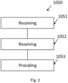
- Fig. 2 discloses a schematic flow diagram of a method 1050 of operating a dimming unit in accordance with the present disclosure.
- the method 1050 is directed to operating a dimming unit in accordance with any of the examples as provided above, wherein said method comprises the steps of:
Landscapes
- Engineering & Computer Science (AREA)
- Computer Networks & Wireless Communication (AREA)
- Circuit Arrangement For Electric Light Sources In General (AREA)
Claims (15)
- Dimmeinheit (1001), die zum Dimmen einer Leuchtdioden- bzw. LED-basierten Beleuchtungsvorrichtung (1009) eingerichtet ist, wobei die Dimmeinheit Folgendes umfasst:- einen Schalter, der zum Empfangen eines Wechselstrom- bzw. AC-Netzsignals und zum Liefern eines Versorgungssignals an die LED-basierte Beleuchtungsvorrichtung basierend auf einem Schaltersteuersignal eingerichtet ist;- eine Steuerung (1005), die zum Bereitstellen des Schaltersteuersignals eingerichtet ist und die eine Nachschlagetabelle umfasst, die eine Beziehung zwischen einem Strombereich einer vorkonfigurierten LED-basierten Beleuchtungsvorrichtung und einem Helligkeitsbereich der vorkonfigurierten LED-basierten Beleuchtungsvorrichtung umfasst;- einen Dimmer (1004), der zum Bereitstellen eines Dimmniveaus für die Steuerung basierend auf einem Eingangsdimmbereich eingerichtet ist;dadurch gekennzeichnet, dass die Steuerung ferner zum Übersetzen des Dimmniveaus in das Schaltersteuersignal derart, dass der Helligkeitsbereich linear zu dem Eingangsdimmbereich ist, unter Verwendung der Nachschlagetabelle eingerichtet ist.
- Dimmeinheit nach Anspruch 1, wobei die Steuerung ferner zum Messen eines Stroms des Versorgungssignals an die LED-basierte Beleuchtungsvorrichtung eingerichtet ist,
wobei die Steuerung zum Kalibrieren des Übersetzens durch Messen des Stroms des Versorgungssignals über einen vollen Eingangsdimmbereich eingerichtet ist. - Dimmeinheit nach einem der vorhergehenden Ansprüche, wobei die Dimmeinheit ferner ein Minimalschwelleneinstellungselement (1007) zum Einstellen einer Minimalschwelle des Dimmniveaus des Dimmers umfasst.
- Dimmeinheit nach einem der vorhergehenden Ansprüche, wobei die Steuerung ein Drahtlosempfangsmittel zum drahtlosen Empfangen des Dimmniveaus von dem Dimmer umfasst.
- Dimmeinheit nach Anspruch 4 wobei die Dimmeinheit ferner ein mobiles Benutzergerät, UE (User Equipment), umfasst, wobei das mobile UE den Dimmer umfasst, und wobei das UE ein Drahtlossendemittel umfasst, das zum drahtlosen Senden des Dimmniveaus an das Drahtlosempfangsmittel der Steuerung eingerichtet ist.
- Dimmeinheit nach einem der Ansprüche 4-5, wobei das Empfangsmittel ferner zum drahtlosen Empfangen von einer beliebigen von Folgendem eingerichtet ist:- einer Nachschlagetabelle zum Anpassen der Beziehung zu einer gewissen LED-basierten Beleuchtungsvorrichtung;- einer Beziehung zwischen einem Strombereich einer vorkonfigurierten LED-basierten Beleuchtungsvorrichtung und einem Helligkeitsbereich der vorkonfigurierten LED-basierten Beleuchtungsvorrichtung zum Einbinden in die Nachschlagetabelle zum Anpassen der Beziehung zu einer gewissen LED-basierten Beleuchtungsvorrichtung.
- Dimmeinheit nach einem der vorhergehenden Ansprüche, wobei der Dimmer ein Potentiometer umfasst, das dazu eingerichtet ist, durch einen Benutzer eingestellt zu werden.
- Leuchtdioden- bzw. LED-basierte Beleuchtungsvorrichtungsbaugruppe, die Folgendes umfasst:- eine Dimmeinheit nach einem der vorhergehenden Ansprüche, und- eine LED-basierte Beleuchtungsvorrichtung, die mit dem Schalter verbunden ist.
- Verfahren (1050) zum Betreiben einer Dimmeinheit nach einem der Ansprüche 1-6, wobei das Verfahren die folgenden Schritte umfasst:- Empfangen (1051), durch den Schalter, der AC-Netzsignalen und Liefern des Versorgungssignals an die LED-basierte Beleuchtungsvorrichtung basierend auf dem Schaltersteuersignal;- Empfangen (1052), durch die Steuerung, von dem Dimmer, des Dimmniveaus basierend auf dem Eingangsdimmbereich; und gekennzeichnet durch:- Liefern (1053), durch die Steuerung, des Schaltersteuersignals an den Schalter durch Übersetzen des Dimmniveaus in das Schaltersteuersignal derart, dass der Helligkeitsbereich linear zu dem Eingangsdimmbereich ist, unter Verwendung der Nachschlagetabelle.
- Verfahren nach Anspruch 9, wobei die Steuerung ferner zum Messen eines Stroms des Versorgungssignals an die LED-basierte Beleuchtungsvorrichtung eingerichtet ist, wobei das Verfahren ferner die folgenden Schritte umfasst:- Kalibrieren des Übersetzens durch Messen des Stroms des Versorgungssignals über einen vollen Eingangsdimmbereich.
- Verfahren nach einem der Ansprüche 9-10, wobei die Dimmeinheit ferner ein Minimalschwelleneinstellungselement zum Einstellen einer Minimalschwelle des Dimmniveaus des Dimmers umfasst, wobei das Verfahren ferner die folgenden Schritte umfasst:- Einstellen, durch das Minimalschwelleneinstellungselement, der Minimalschwelle des Dimmniveaus.
- Verfahren nach einem der Ansprüche 9-11, wobei die Steuerung ein Drahtlosempfangsmittel zum drahtlosen Empfangen des Dimmniveaus von dem Dimmer umfasst, und wobei das Verfahren ferner den folgenden Schritt umfasst:- Empfangen, durch das Drahtlosempfangsmittel, des Dimmniveaus von dem Dimmer.
- Verfahren nach einem der Ansprüche 9-11, wobei die Dimmeinheit ferner ein mobiles Benutzergerät, UE, umfasst, wobei das mobile UE den Dimmer umfasst, und wobei das UE ein Drahtlossendemittel umfasst, wobei das Verfahren ferner den folgenden Schritt umfasst:- drahtloses Senden, durch das Drahtlossendemittel, des Dimmniveaus an das Drahtlosempfangsmittel, das in der Steuerung enthalten ist.
- Verfahren nach einem der Ansprüche 12-13, wobei das Empfangsmittel ferner zum drahtlosen Empfangen von einer beliebigen von Folgendem eingerichtet ist:- einer Nachschlagetabelle zum Anpassen der Beziehung zu einer gewissen LED-basierten Beleuchtungsvorrichtung;- einer Beziehung zwischen einem Strombereich einer vorkonfigurierten LED-basierten Beleuchtungsvorrichtung und einem Helligkeitsbereich der vorkonfigurierten LED-basierten Beleuchtungsvorrichtung zum Einbinden in die Nachschlagetabelle zum Anpassen der Beziehung zu einer gewissen LED-basierten Beleuchtungsvorrichtung.
- Computerprogrammprodukt, das ein computerlesbares Medium mit darauf gespeicherten Anweisungen umfasst, die, wenn sie durch eine Dimmeinheit nach einem der Ansprüche 1-7 ausgeführt werden, die Dimmeinheit zum Durchführen eines Verfahrens nach einem der Ansprüche 9-14 veranlassen.
Applications Claiming Priority (2)
| Application Number | Priority Date | Filing Date | Title |
|---|---|---|---|
| NL2022772A NL2022772B1 (en) | 2019-03-20 | 2019-03-20 | A dimming unit arranged for dimming a Light Emitting Diode, LED, based lighting device as well as a corresponding method. |
| PCT/NL2020/050184 WO2020190139A1 (en) | 2019-03-20 | 2020-03-19 | A dimming unit arranged for dimming a light emitting diode, led, based lighting device as well as a corresponding method |
Publications (3)
| Publication Number | Publication Date |
|---|---|
| EP3942902A1 EP3942902A1 (de) | 2022-01-26 |
| EP3942902C0 EP3942902C0 (de) | 2025-05-07 |
| EP3942902B1 true EP3942902B1 (de) | 2025-05-07 |
Family
ID=66380089
Family Applications (1)
| Application Number | Title | Priority Date | Filing Date |
|---|---|---|---|
| EP20714002.1A Active EP3942902B1 (de) | 2019-03-20 | 2020-03-19 | Dimmeinheit zum dimmen einer leuchtdiode, led, beleuchtungsvorrichtung und entsprechendes verfahren |
Country Status (6)
| Country | Link |
|---|---|
| US (1) | US20220151038A1 (de) |
| EP (1) | EP3942902B1 (de) |
| CN (1) | CN113647200A (de) |
| AU (1) | AU2020240931A1 (de) |
| NL (1) | NL2022772B1 (de) |
| WO (1) | WO2020190139A1 (de) |
Families Citing this family (2)
| Publication number | Priority date | Publication date | Assignee | Title |
|---|---|---|---|---|
| NL2026739B1 (en) * | 2020-10-23 | 2022-06-16 | Klemko Techniek B V | A dimming unit arranged for dimming a Light Emitting Diode, LED, based lighting device, a LED based lighting device assembly comprising such a dimming unit and a method for operating such a dimming unit |
| JP2026511059A (ja) * | 2023-03-21 | 2026-04-10 | シグニファイ ホールディング ビー ヴィ | 単一の負荷に対する複数のサブドライバを用いた高効率調光 |
Family Cites Families (8)
| Publication number | Priority date | Publication date | Assignee | Title |
|---|---|---|---|---|
| GB2421367B (en) * | 2004-12-20 | 2008-09-03 | Stephen Bryce Hayes | Lighting apparatus and method |
| ES2298987T3 (es) * | 2005-02-02 | 2008-05-16 | Patent-Treuhand-Gesellschaft Fur Elektrische Gluhlampen Mbh | Metodo y sistema para atenuar fuentes de luz. |
| US7872423B2 (en) * | 2008-02-19 | 2011-01-18 | Lutron Electronics Co., Inc. | Smart load control device having a rotary actuator |
| TWI465151B (zh) * | 2011-12-07 | 2014-12-11 | Richtek Technology Corp | 控制led亮度的調光控制器及方法 |
| US9661697B2 (en) * | 2013-03-14 | 2017-05-23 | Laurence P. Sadwick | Digital dimmable driver |
| US9860949B2 (en) * | 2013-08-22 | 2018-01-02 | The L.D. Kichler Co. | Individually addressable dimmer systems and methods |
| WO2015061237A1 (en) * | 2013-10-21 | 2015-04-30 | Heinz Grether Pc | Brightness control for an led display |
| KR20150078260A (ko) * | 2013-12-30 | 2015-07-08 | 삼성디스플레이 주식회사 | 표시 장치, 이를 포함하는 다중 표시 장치, 및 표시 장치의 구동 방법 |
-
2019
- 2019-03-20 NL NL2022772A patent/NL2022772B1/en active
-
2020
- 2020-03-19 US US17/440,558 patent/US20220151038A1/en not_active Abandoned
- 2020-03-19 WO PCT/NL2020/050184 patent/WO2020190139A1/en not_active Ceased
- 2020-03-19 CN CN202080022863.2A patent/CN113647200A/zh active Pending
- 2020-03-19 AU AU2020240931A patent/AU2020240931A1/en not_active Abandoned
- 2020-03-19 EP EP20714002.1A patent/EP3942902B1/de active Active
Also Published As
| Publication number | Publication date |
|---|---|
| AU2020240931A1 (en) | 2021-09-30 |
| US20220151038A1 (en) | 2022-05-12 |
| CN113647200A (zh) | 2021-11-12 |
| EP3942902C0 (de) | 2025-05-07 |
| EP3942902A1 (de) | 2022-01-26 |
| WO2020190139A1 (en) | 2020-09-24 |
| NL2022772B1 (en) | 2020-09-28 |
Similar Documents
| Publication | Publication Date | Title |
|---|---|---|
| US20230180359A1 (en) | Multiple location load control system | |
| US10051706B2 (en) | Current splitter for LED lighting system | |
| US10652970B2 (en) | Radio frequency (RF) controlled lamp with dimmer compatibility | |
| KR101727093B1 (ko) | Ac 선전압에 정보를 인코딩하는 방법 및 장치 | |
| US20180027626A1 (en) | Color-temperature adjustable led lighting device and method for adjusting color temperature of led lighting device | |
| US9681508B2 (en) | Light modulation control unit, illumination system, and facility apparatus | |
| TW201336346A (zh) | 發光元件驅動電路及其控制方法 | |
| CN107787089B (zh) | 一种led灯具调控系统 | |
| EP3942902B1 (de) | Dimmeinheit zum dimmen einer leuchtdiode, led, beleuchtungsvorrichtung und entsprechendes verfahren | |
| CN103561503B (zh) | 一种适用于ac切相调光的led驱动电源 | |
| US20150156839A1 (en) | Method and apparatus for adjusting color temperature of luminance of lamp | |
| CN211406383U (zh) | Led驱动电路以及led调节系统 | |
| HK40060228A (en) | A dimming unit arranged for dimming a light emitting diode, led, based lighting device as well as a corresponding method | |
| NL2026739B1 (en) | A dimming unit arranged for dimming a Light Emitting Diode, LED, based lighting device, a LED based lighting device assembly comprising such a dimming unit and a method for operating such a dimming unit | |
| EP3393209A1 (de) | System zur regelung des minimalen ausgangsstroms einer led-dimmstromversorgung | |
| EP2806712A1 (de) | Anwendungsschaltung und Steuerverfahren dafür | |
| CN113646981A (zh) | Led调光组件的实现方法及led调光组件 | |
| JP2015185380A (ja) | Led照明装置 |
Legal Events
| Date | Code | Title | Description |
|---|---|---|---|
| STAA | Information on the status of an ep patent application or granted ep patent |
Free format text: STATUS: UNKNOWN |
|
| STAA | Information on the status of an ep patent application or granted ep patent |
Free format text: STATUS: THE INTERNATIONAL PUBLICATION HAS BEEN MADE |
|
| PUAI | Public reference made under article 153(3) epc to a published international application that has entered the european phase |
Free format text: ORIGINAL CODE: 0009012 |
|
| STAA | Information on the status of an ep patent application or granted ep patent |
Free format text: STATUS: REQUEST FOR EXAMINATION WAS MADE |
|
| 17P | Request for examination filed |
Effective date: 20210916 |
|
| AK | Designated contracting states |
Kind code of ref document: A1 Designated state(s): AL AT BE BG CH CY CZ DE DK EE ES FI FR GB GR HR HU IE IS IT LI LT LU LV MC MK MT NL NO PL PT RO RS SE SI SK SM TR |
|
| DAV | Request for validation of the european patent (deleted) | ||
| DAX | Request for extension of the european patent (deleted) | ||
| STAA | Information on the status of an ep patent application or granted ep patent |
Free format text: STATUS: EXAMINATION IS IN PROGRESS |
|
| 17Q | First examination report despatched |
Effective date: 20230601 |
|
| P01 | Opt-out of the competence of the unified patent court (upc) registered |
Effective date: 20230527 |
|
| REG | Reference to a national code |
Ref country code: DE Ref legal event code: R079 Free format text: PREVIOUS MAIN CLASS: H05B0045100000 Ipc: H05B0047175000 Ref country code: DE Ref legal event code: R079 Ref document number: 602020050788 Country of ref document: DE Free format text: PREVIOUS MAIN CLASS: H05B0045100000 Ipc: H05B0047175000 |
|
| GRAP | Despatch of communication of intention to grant a patent |
Free format text: ORIGINAL CODE: EPIDOSNIGR1 |
|
| STAA | Information on the status of an ep patent application or granted ep patent |
Free format text: STATUS: GRANT OF PATENT IS INTENDED |
|
| GRAS | Grant fee paid |
Free format text: ORIGINAL CODE: EPIDOSNIGR3 |
|
| RIC1 | Information provided on ipc code assigned before grant |
Ipc: H05B 47/19 20200101ALI20250127BHEP Ipc: H05B 45/10 20200101ALI20250127BHEP Ipc: H05B 47/175 20200101AFI20250127BHEP |
|
| INTG | Intention to grant announced |
Effective date: 20250211 |
|
| GRAA | (expected) grant |
Free format text: ORIGINAL CODE: 0009210 |
|
| STAA | Information on the status of an ep patent application or granted ep patent |
Free format text: STATUS: THE PATENT HAS BEEN GRANTED |
|
| AK | Designated contracting states |
Kind code of ref document: B1 Designated state(s): AL AT BE BG CH CY CZ DE DK EE ES FI FR GB GR HR HU IE IS IT LI LT LU LV MC MK MT NL NO PL PT RO RS SE SI SK SM TR |
|
| REG | Reference to a national code |
Ref country code: GB Ref legal event code: FG4D |
|
| REG | Reference to a national code |
Ref country code: CH Ref legal event code: EP |
|
| REG | Reference to a national code |
Ref country code: DE Ref legal event code: R096 Ref document number: 602020050788 Country of ref document: DE |
|
| REG | Reference to a national code |
Ref country code: IE Ref legal event code: FG4D |
|
| U01 | Request for unitary effect filed |
Effective date: 20250606 |
|
| U07 | Unitary effect registered |
Designated state(s): AT BE BG DE DK EE FI FR IT LT LU LV MT NL PT RO SE SI Effective date: 20250616 |
|
| P04 | Withdrawal of opt-out of the competence of the unified patent court (upc) registered |
Free format text: CASE NUMBER: APP_28073/2025 Effective date: 20250611 |
|
| PG25 | Lapsed in a contracting state [announced via postgrant information from national office to epo] |
Ref country code: ES Free format text: LAPSE BECAUSE OF FAILURE TO SUBMIT A TRANSLATION OF THE DESCRIPTION OR TO PAY THE FEE WITHIN THE PRESCRIBED TIME-LIMIT Effective date: 20250507 |
|
| PG25 | Lapsed in a contracting state [announced via postgrant information from national office to epo] |
Ref country code: NO Free format text: LAPSE BECAUSE OF FAILURE TO SUBMIT A TRANSLATION OF THE DESCRIPTION OR TO PAY THE FEE WITHIN THE PRESCRIBED TIME-LIMIT Effective date: 20250807 Ref country code: GR Free format text: LAPSE BECAUSE OF FAILURE TO SUBMIT A TRANSLATION OF THE DESCRIPTION OR TO PAY THE FEE WITHIN THE PRESCRIBED TIME-LIMIT Effective date: 20250808 |
|
| PG25 | Lapsed in a contracting state [announced via postgrant information from national office to epo] |
Ref country code: PL Free format text: LAPSE BECAUSE OF FAILURE TO SUBMIT A TRANSLATION OF THE DESCRIPTION OR TO PAY THE FEE WITHIN THE PRESCRIBED TIME-LIMIT Effective date: 20250507 |
|
| PG25 | Lapsed in a contracting state [announced via postgrant information from national office to epo] |
Ref country code: HR Free format text: LAPSE BECAUSE OF FAILURE TO SUBMIT A TRANSLATION OF THE DESCRIPTION OR TO PAY THE FEE WITHIN THE PRESCRIBED TIME-LIMIT Effective date: 20250507 |
|
| PG25 | Lapsed in a contracting state [announced via postgrant information from national office to epo] |
Ref country code: RS Free format text: LAPSE BECAUSE OF FAILURE TO SUBMIT A TRANSLATION OF THE DESCRIPTION OR TO PAY THE FEE WITHIN THE PRESCRIBED TIME-LIMIT Effective date: 20250807 |
|
| PG25 | Lapsed in a contracting state [announced via postgrant information from national office to epo] |
Ref country code: IS Free format text: LAPSE BECAUSE OF FAILURE TO SUBMIT A TRANSLATION OF THE DESCRIPTION OR TO PAY THE FEE WITHIN THE PRESCRIBED TIME-LIMIT Effective date: 20250907 |
|
| PG25 | Lapsed in a contracting state [announced via postgrant information from national office to epo] |
Ref country code: SM Free format text: LAPSE BECAUSE OF FAILURE TO SUBMIT A TRANSLATION OF THE DESCRIPTION OR TO PAY THE FEE WITHIN THE PRESCRIBED TIME-LIMIT Effective date: 20250507 |
|
| PG25 | Lapsed in a contracting state [announced via postgrant information from national office to epo] |
Ref country code: CZ Free format text: LAPSE BECAUSE OF FAILURE TO SUBMIT A TRANSLATION OF THE DESCRIPTION OR TO PAY THE FEE WITHIN THE PRESCRIBED TIME-LIMIT Effective date: 20250507 |
|
| PG25 | Lapsed in a contracting state [announced via postgrant information from national office to epo] |
Ref country code: SK Free format text: LAPSE BECAUSE OF FAILURE TO SUBMIT A TRANSLATION OF THE DESCRIPTION OR TO PAY THE FEE WITHIN THE PRESCRIBED TIME-LIMIT Effective date: 20250507 |
|
| PLBE | No opposition filed within time limit |
Free format text: ORIGINAL CODE: 0009261 |
|
| STAA | Information on the status of an ep patent application or granted ep patent |
Free format text: STATUS: NO OPPOSITION FILED WITHIN TIME LIMIT |
|
| REG | Reference to a national code |
Ref country code: CH Ref legal event code: L10 Free format text: ST27 STATUS EVENT CODE: U-0-0-L10-L00 (AS PROVIDED BY THE NATIONAL OFFICE) Effective date: 20260318 |
|
| 26N | No opposition filed |
Effective date: 20260210 |