EP3942243B1 - Silencer - Google Patents
Silencer Download PDFInfo
- Publication number
- EP3942243B1 EP3942243B1 EP20713263.0A EP20713263A EP3942243B1 EP 3942243 B1 EP3942243 B1 EP 3942243B1 EP 20713263 A EP20713263 A EP 20713263A EP 3942243 B1 EP3942243 B1 EP 3942243B1
- Authority
- EP
- European Patent Office
- Prior art keywords
- silencer
- intermediate module
- module element
- radial
- sleeve portion
- Prior art date
- Legal status (The legal status is an assumption and is not a legal conclusion. Google has not performed a legal analysis and makes no representation as to the accuracy of the status listed.)
- Active
Links
Images


Classifications
-
- F—MECHANICAL ENGINEERING; LIGHTING; HEATING; WEAPONS; BLASTING
- F41—WEAPONS
- F41A—FUNCTIONAL FEATURES OR DETAILS COMMON TO BOTH SMALLARMS AND ORDNANCE, e.g. CANNONS; MOUNTINGS FOR SMALLARMS OR ORDNANCE
- F41A21/00—Barrels; Gun tubes; Muzzle attachments; Barrel mounting means
- F41A21/30—Silencers
-
- F—MECHANICAL ENGINEERING; LIGHTING; HEATING; WEAPONS; BLASTING
- F41—WEAPONS
- F41A—FUNCTIONAL FEATURES OR DETAILS COMMON TO BOTH SMALLARMS AND ORDNANCE, e.g. CANNONS; MOUNTINGS FOR SMALLARMS OR ORDNANCE
- F41A21/00—Barrels; Gun tubes; Muzzle attachments; Barrel mounting means
- F41A21/28—Gas-expansion chambers; Barrels provided with gas-relieving ports
-
- F—MECHANICAL ENGINEERING; LIGHTING; HEATING; WEAPONS; BLASTING
- F41—WEAPONS
- F41A—FUNCTIONAL FEATURES OR DETAILS COMMON TO BOTH SMALLARMS AND ORDNANCE, e.g. CANNONS; MOUNTINGS FOR SMALLARMS OR ORDNANCE
- F41A21/00—Barrels; Gun tubes; Muzzle attachments; Barrel mounting means
- F41A21/32—Muzzle attachments or glands
-
- F—MECHANICAL ENGINEERING; LIGHTING; HEATING; WEAPONS; BLASTING
- F41—WEAPONS
- F41A—FUNCTIONAL FEATURES OR DETAILS COMMON TO BOTH SMALLARMS AND ORDNANCE, e.g. CANNONS; MOUNTINGS FOR SMALLARMS OR ORDNANCE
- F41A21/00—Barrels; Gun tubes; Muzzle attachments; Barrel mounting means
- F41A21/32—Muzzle attachments or glands
- F41A21/325—Mountings for muzzle attachments
Definitions
- the present invention relates to a silencer for a firearm, in particular an automatic or semi-automatic firearm, where the silencer comprises at a muzzle portion and an attachment portion, at least one module being arranged between said portions, where the silencer is intended to be releasably connected to a barrel of the firearm or to attachment element(s) arranged on the barrel of the firearm.
- Silencers for a firearm are well known in the prior art.
- the advantages of reducing the muzzle blast, noise and flash signature of a discharging firearm are well known.
- adjustable gas blocks have been used with autoloading rifles as a means to collect, restrict, and direct the flow of gas from the barrel into the gas operating system.
- reliable operation of the host firearm is ensured while also ensuring that recoiling parts are not actuated with undue force resulting in malfunctions or premature wear and breakage of parts.
- US 8.857.306 B1 relates to a firearm suppressor, where an inertial damping apparatus in communication with a dynamic suppression mechanism for a firearm.
- the apparatus is in communication with both a muzzle of a projectile release device and with the suppressor.
- the apparatus dynamically extends between different states of compression.
- the apparatus is comprised of a body and an axial sleeve, with the sleeve functioning to guide movement of the body and to hold a first end of axially variable material in position when subject to compression.
- US 2014/158459 A1 relates to a firearm sound suppressor, where the suppressor can be selectively oriented relative to the firearm.
- the suppressor has an elongate body, a piston assembly and a cam assembly.
- a piston of the piston assembly can be fixedly attached to the barrel of a firearm.
- An indexing ring is radially fixed relative to the piston.
- the cam lever is selectively movable between a second position, in which the indexing ring is fixed relative to the elongate body, and a first position, in which the indexing ring can rotate relative to the elongate body.
- US 2013/263490 A1 relates to an interchangeable, modular firearm muzzle mountable system, where the system includes a first firearm muzzle mountable device and a second firearm muzzle mountable device. Each device can have an inlet end coupling feature proximate to an inlet end of a central chamber and an outlet end coupling feature proximate to an outlet of the central chamber.
- the central chamber can be oriented along a central axis within an outer shell and the inlet and the outlet can be configured to allow a projectile from a firearm to pass along the central axis.
- the inlet end coupling feature of the first device can be removably couplable with a muzzle end of a firearm and the inlet end coupling feature of the second device can be removably couplable with the outlet end coupling feature of the first device beyond the muzzle end of the firearm.
- US 2018/356173 A relates to modular gun silencer, where the gun silencer includes an outer tube and a plurality of chamber separators suspended through a tensile force within a bore of the outer tube and defining chambers between each pair of chamber separators in the silencer. An outer edge of the chamber separators is spaced apart from an inner surface of the tube to allow gas equalization between the chambers.
- a plurality of tube portions separates the chamber separators from each other and from the proximal and distal ends of the silencer assembly.
- the tube portions define a continuous center tube suspended in tension within the outer tube and through which the projectile travels.
- the tube portions can have angled openings through which gas discharge exits into the chambers. Rotatable sleeves can be disposed over the tube portions to further disrupt gas flow and dissipate heat and sound.
- US 2018/202742 A relates to a modular suppressor kit, where the suppressor kit includes a modular suppressor and suppressor tool.
- the modular suppressor includes a barrel attachment portion that has a central passage.
- the barrel attachment portion is configured to attach to a firearm barrel.
- the modular suppressor includes a cap portion that has a central passage.
- the modular suppressor includes a body portion that has an internal baffle structure and an expansion chamber. The body portion is attachable to, and separable from, the barrel attachment portion and the cap portion.
- the body portion defines a central passage that is alignable with the central passage of the barrel attachment portion and the central passage of the cap portion.
- the suppressor tool has an engagement feature for engaging with at least one of the barrel attachment portion, cap portion, and body portion.
- WO2016/126227 constitutes other relevant prior art.
- the object of the present invention is to provide a silencer that controls the flow direction of the exhaust gases, which is modular, and comprises few parts and at the same time is light in weight.
- the present invention seeks to provide an alternative silencer, which offers satisfactory diversion of the exhaust gases' direction of flow while at the same time being modular and consisting of a small number of parts.
- the present invention relates to a silencer for a firearm, where the silencer is designed to be detachably connectable to one or more attachment elements arranged on a barrel of the firearm, or to the barrel of the firearm.
- a silencer for firearms where the silencer comprises an attachment part for releasable connection to a barrel of a firearm and a muzzle part, where at least one intermediate module element is arranged between the attachment part and the muzzle part, where the attachment part, the at least one intermediate module element and the muzzle part, when connected to each other in appropriate ways, will form the silencer.
- Each of the attachment part, the intermediate module element and the muzzle part comprises an outer sleeve portion, where the outer sleeve portions, when the silencer is assembled, will form an outer surface of the silencer.
- Each of the intermediate module elements comprises further an inner sleeve portion and a core portion, where the inner sleeve portion form a part of an inner surface of the silencer and where the core portion comprises a throughgoing bore. Furthermore, the outer and inner sleeve portion is connected through a radial part, where the radial part is provided with a plurality of axial throughgoing openings around it's periphery.
- the outer sleeve portion and inner sleeve portion of the intermediate module element(s) form a volume defining a first passage for exhaust gases, and the inner sleeve portion and the core portion form a volume defining a second passage for exhaust gases.
- the silencer according to the present invention may comprise one or a plurality of intermediate module elements, for instance two, three or more intermediate module elements, where the different parts and elements in appropriate ways are connected to each other to form the silencer.
- the exhaust gases after firing of a cartridge or shell from the firearm will enter into a cavity formed in the attachment part of the silencer, where the exhaust gases are expanded, whereafter a part of the expanded exhaust gases will be forced and compressed through the axial throughgoing openings provided around the periphery of the radial part of the attachment part and guided into a cavity formed in the subsequent intermediate module element.
- a part of the expanded exhaust gases will be forced and compressed through the throughgoing bore of the core portion and into a cavity formed between the core portion and the inner sleeve portion of the attachment part.
- a rest part of the expanded exhaust gas will be forced back and out of the cavity formed in the attachment part, where this rest part of the expanded exhaust gases will be utilized as means to operate the action of the host firearm.
- the silencer for example comprises two intermediate module elements, where the exhaust gases will escape out from the muzzle part of the silencer through the throughgoing openings provided in the muzzle part.
- the part of the exhaust gases that is guided into the cavity formed between the core portion and the inner sleeve portion of the intermediate module element(s) will escape out from the muzzle part through the throughgoing bore of the core element of the intermediate module element(s).
- each of the attachment part and the muzzle part may comprise a radial part provided with a plurality of axial throughgoing openings around a periphery of the radial part, and a center opening.
- the axial throughgoing openings may be arranged with a same distance between them, but it should be understood that the axial throughgoing openings could be arranged with different distance between then, at least for some of the axial throughgoing openings.
- the muzzle part may, on an inside of the outer sleeve portion and on an opposite side of the radial part, be provided with a threaded area or portion.
- the attachment part may, on an inside of the outer sleeve and on an opposite side of the radial part, be provided with a threaded area or portion.
- the inner sleeve portion and the core portion of each of the intermediate module elements may extend outward in one direction from the radial part, and the outer sleeve extends outward in an opposite direction from the radial part.
- each of the attachment part and the intermediate module element(s) is/are, on an inside of the outer sleeve portion provided with an internal or inner threaded portion, while an outside of the radial part of each intermediate module element is provided with an external or outer threaded portion.
- the internal threaded area or portion of the attachment part will allow the silencer to be releasably connected to a barrel of a firearm, or to attachment element(s) arranged on the barrel of the firearm.
- the barrel of the firearm or the attachment element(s) are then provided with an external or outer threaded portion.
- the external threaded portion of the attachment part and the internal threaded portion of an intermediate module element will allow a connection between the attachment part and the intermediate module element, while the external threaded portion of the intermediate module element and the internal threaded portion of the muzzle part or alternatively a subsequent following intermediate module element will allow a connection between the intermediate module element and the muzzle part, or the connection between two adjacent or subsequent intermediate module elements.
- each core portion of the intermediate module elements may be, around a periphery of the core portion, provided with a plurality of radial throughgoing openings, where the plurality of radial throughgoing openings form a connection with the throughgoing bore of the core portion.
- the number of radial throughgoing openings could vary from one to eight or even more, this depending on ammunition variance (i.e. caliber), and other factors, such as charge (i.e. gun powder present in the cartridges) or the like.
- the plurality of radial throughgoing openings provided in the intermediate module elements may be provided to form an angle with the throughgoing bore of the core portion.
- the radial throughgoing openings may have a circular, oval, polygonal or square form.
- a diameter of the inner sleeve portions may be larger than a diameter of the core portion.
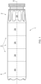
- Figure 1 shows a silencer 1 for firearms according to the present invention in an assembled state, where the silencer 1 comprises an attachment part 2, three intermediate module elements 3 and a muzzle part 4 that are connected to each other in appropriate ways.
- the length of the silencer 1 can be adjusted and thereby the effect thereof.
- the different parts 2, 3, 4 are arranged in alignment with each other and have a common center axis 6 extending over a length of the silencer 1.
- the attachment part 2 can be releasably connected to a barrel of a firearm (not shown) or to attachment element(s) (not shown) arranged on the barrel of the firearm.
- silencer 1 is shown to comprise three intermediate module elements 3, it should be understood that the silencer 1 according to the present invention could comprise fewer intermediate module elements 3, for instance one or two, or more intermediate module elements 3, for instance four or more.
- the firearm may, for example, be an automatic or semi-automatic rifle or the like.
- each of the attachment part 2, each intermediate module element 3 and muzzle part 4, see also figure 2 comprises an outer sleeve portion 2A, 3A, 4A, each of the outer sleeve portions 2A, 3A, 4A forming a part of an outer surface of the silencer 1, and together form the outer surface of the silencer 1 when the silencer 1 is assembled.
- Each of the intermediate module element 3 comprises further an inner sleeve portion 3B and a core portion 3C, where each of the inner sleeve portions 3B forms a part of an inner surface of the silencer 1 when the silencer 1 is assembled.
- a throughgoing bore 3D is formed in each of the core portions 3C of the intermediate module element(s) 3.
- each of the attachment part 2 and the muzzle part 4 comprise a radial part 2E, 4E provided with a plurality of axial throughgoing openings 2F, 4F around a periphery of the radial part 2E, 4E and a center opening.
- the plurality of axial throughgoing openings 2F, 4F may be arranged with a same distance between them, but it should be understood that the axial throughgoing openings 2F, 4F could be arranged with different distance between then, at least for some of the axial throughgoing openings 2F, 4F.
- each intermediate module element 3 The outer sleeve portion 3A and the inner sleeve portion 3B of each intermediate module element 3 are connected to each other through a radial part 3E.
- a plurality of axial throughgoing openings 2F are provided around a periphery of the radial part of the attachment part 2, and a plurality of axial throughgoing openings 3F are provided around a periphery of the radial part 3E of each intermediate module element 3.
- Exhaust gases can then through the above arrangement of the respective outer sleeve portions 2A, 3A, 4A of the attachment part 2, the intermediate module element(s) 3 and the muzzle part 4 together with the inner sleeve portions 3B of the intermediate module element(s) and the radial parts 2E, 3E, 4E of the attachment part 2, the intermediate module element(s) 3 and the muzzle part 4 escape through the plurality of axial throughgoing openings 2F, 3F, 4F from one part or element to a subsequent part or element, for instance from the attachment part 2 and to a subsequent following intermediate module element 3, from the intermediate module element 3 and to the subsequent following intermediate module element 3 or from an intermediate module element 3 to a subsequent following muzzle part 4, whereafter the exhaust gasses can escape out from the silencer 1 through the axial throughgoing openings 4F of the muzzle part 4.
- the outer sleeve portions 2A, 3A, 4A of the attachment part 2, the intermediate module element(s) 3 and the muzzle part 4, with the inner sleeve portions 3B of the intermediate module element(s) 3 will form a volume or cavity defining a first passage for exhaust gases, and the inner sleeve portions 3B and the core portions 3C of the intermediate module element(s) 3 will form a volume or cavity defining a second passage for exhaust gases through the silencer 1.
- the exhaust gases after firing of a cartridge or shell from a firearm will enter into a volume or cavity formed in the attachment part 2 of the silencer 1, where the exhaust gases are expanded in this volume or cavity, whereafter a part of the expanded exhaust gases will be forced and compressed through the axial throughgoing openings 2F provided around the periphery of the radial part 2E of the attachment part 2 and thereafter guided into a volume or cavity formed in the subsequent following intermediate module element 3.
- a part of the expanded exhaust gases will be forced and compressed through the center of the attachment part 2 and thereafter guided into the throughgoing bore 3D of the subsequent following intermediate module element 3.
- a rest part of the expanded exhaust gas will be forced back and out of the volume or cavity formed in the attachment part 2, where this rest part of the expanded exhaust gases will be utilized as means to operate the action of the host firearm.
- the process will be repeated in the subsequent following intermediate module element 3, where the exhaust gases once again are expanded in the volume or cavity formed in this intermediate module element 3 and thereafter forced and compressed through the axial throughgoing openings 3F provided around the periphery of the radial part 3E of this intermediate module element 3 and guided into a volume or cavity formed in the subsequent following muzzle part 4, if the silencer 1, for example comprises only one intermediate module element 3, where the exhaust gases will escape out from the muzzle part 4 of the silencer 1 through the axial throughgoing openings 4F provided in the muzzle part 4.
- the silencer 1 comprises two or more intermediate module elements 3, then the exhaust gases will be expanded once again in each intermediate module element 3 as described above and thereafter forced and compressed through the axial throughgoing openings 3F provided around the periphery of the radial part 3E of this intermediate module element 3 and guided into a volume or cavity formed in the subsequent following muzzle part 4.
- the part of the exhaust gases that are guided into the cavity 3H formed between the core portion 3C and the inner sleeve portion 3B of this intermediate module element 3 will escape out from this intermediate module element 3 and into the subsequent following intermediate module element 3 and eventually out from the muzzle part 4 through the throughgoing bore 3D of the core portion 3C of the adjacent intermediate module element 3.
- each of the intermediate module elements 3 are extended outward in one direction from the radial part 3E, and the outer sleeve 3A extends outward in an opposite direction from the radial part 3E.
- the outer sleeve portion 2A of the attachment part 2 will extend over the inner sleeve portion 3B of the subsequent following intermediate module element 3.
- the inner sleeve portion 3B and the core portion 3C of this intermediate module element 3 will extend into the outer sleeve portion 3A of a subsequent following intermediate module element 3 or into a subsequent following muzzle part 4.
- the attachment part 2 and the intermediate module element 3 are, on an inside of the outer sleeve 2A, 3A, provided with a threaded portion, while an outside of the radial parts 3E of the intermediate module elements 3 are provided with a threaded portion.
- the core portion 3C of the intermediate module element 3, around a periphery of the core portion 3C, is provided with a plurality of radial throughgoing openings 3G, where the plurality of the radial throughgoing openings 3G form a connection with the throughgoing bore 3D of the intermediate module element 3 and cavity 3H.
Landscapes
- Engineering & Computer Science (AREA)
- General Engineering & Computer Science (AREA)
- Exhaust Silencers (AREA)
Description
- The present invention relates to a silencer for a firearm, in particular an automatic or semi-automatic firearm, where the silencer comprises at a muzzle portion and an attachment portion, at least one module being arranged between said portions, where the silencer is intended to be releasably connected to a barrel of the firearm or to attachment element(s) arranged on the barrel of the firearm.
- Silencers for a firearm are well known in the prior art. The advantages of reducing the muzzle blast, noise and flash signature of a discharging firearm are well known.
- The need to regulate the flow of gas between the barrel and operating system of a firearm has been a concern since the invention of autoloading firearms. Gas is generated during the combustion of gun powder present in the cartridges used in firearms. This gas expands violently to push the bullet out of the firearm's barrel. These expanding gases are also utilized as a means to operate the action of the host firearm. In modern firearms, the preferred method of facilitating the function of an autoloading weapon is as follows. A hole, or gas port, is placed through the barrel, generally on the top. Location of the gas port varies between operating systems and gas port size is chosen to allow a broad range of ammunition to be utilized while guaranteeing the reliable function of the host firearm. Unfortunately, due to varying lengths of barrels, ammunition variance, and other factors, it is very difficult to choose a gas port size which universally works under all conditions. A popular way of compensating for these problems is to incorporate an adjustable gas block into the operating system.
- Traditionally, adjustable gas blocks have been used with autoloading rifles as a means to collect, restrict, and direct the flow of gas from the barrel into the gas operating system. By controlling the amount of gas directed into the operating system, reliable operation of the host firearm is ensured while also ensuring that recoiling parts are not actuated with undue force resulting in malfunctions or premature wear and breakage of parts.
- In response to military request and an increased interest in both civilian and police markets, recent firearm designs have incorporated adjustable gas blocks designed to be used in conjunction with noise suppressors or silencers. Noise suppressors provide a means to redirect and expand the gases generated from the discharge of a firearm so that the resulting flash and sound generated by the firearm is minimized or eliminated. As a result, back pressure is generated, forcing more gas into the firearm's operating system. This extra gas, or back pressure, increases the firing rate of a weapon when operating at full auto, fouls the weapon leading to premature malfunction, can cause a variety of feeding and extraction problems, and causes premature wear on the reciprocating parts of the operating system. As a result, regulating the flow of gas into a firearm's operating system and optimizing that flow for use with and without a noise suppressor has become a primary purpose of modern adjustable gas blocks.
-
US 8.857.306 B1 relates to a firearm suppressor, where an inertial damping apparatus in communication with a dynamic suppression mechanism for a firearm. The apparatus is in communication with both a muzzle of a projectile release device and with the suppressor. The apparatus dynamically extends between different states of compression. The apparatus is comprised of a body and an axial sleeve, with the sleeve functioning to guide movement of the body and to hold a first end of axially variable material in position when subject to compression. -
US 2014/158459 A1 relates to a firearm sound suppressor, where the suppressor can be selectively oriented relative to the firearm. The suppressor has an elongate body, a piston assembly and a cam assembly. A piston of the piston assembly can be fixedly attached to the barrel of a firearm. An indexing ring is radially fixed relative to the piston. The cam lever is selectively movable between a second position, in which the indexing ring is fixed relative to the elongate body, and a first position, in which the indexing ring can rotate relative to the elongate body. -
US 2013/263490 A1 relates to an interchangeable, modular firearm muzzle mountable system, where the system includes a first firearm muzzle mountable device and a second firearm muzzle mountable device. Each device can have an inlet end coupling feature proximate to an inlet end of a central chamber and an outlet end coupling feature proximate to an outlet of the central chamber. The central chamber can be oriented along a central axis within an outer shell and the inlet and the outlet can be configured to allow a projectile from a firearm to pass along the central axis. The inlet end coupling feature of the first device can be removably couplable with a muzzle end of a firearm and the inlet end coupling feature of the second device can be removably couplable with the outlet end coupling feature of the first device beyond the muzzle end of the firearm. -
US 2018/356173 A relates to modular gun silencer, where the gun silencer includes an outer tube and a plurality of chamber separators suspended through a tensile force within a bore of the outer tube and defining chambers between each pair of chamber separators in the silencer. An outer edge of the chamber separators is spaced apart from an inner surface of the tube to allow gas equalization between the chambers. A plurality of tube portions separates the chamber separators from each other and from the proximal and distal ends of the silencer assembly. The tube portions define a continuous center tube suspended in tension within the outer tube and through which the projectile travels. The tube portions can have angled openings through which gas discharge exits into the chambers. Rotatable sleeves can be disposed over the tube portions to further disrupt gas flow and dissipate heat and sound. -
US 2018/202742 A relates to a modular suppressor kit, where the suppressor kit includes a modular suppressor and suppressor tool. The modular suppressor includes a barrel attachment portion that has a central passage. The barrel attachment portion is configured to attach to a firearm barrel. The modular suppressor includes a cap portion that has a central passage. The modular suppressor includes a body portion that has an internal baffle structure and an expansion chamber. The body portion is attachable to, and separable from, the barrel attachment portion and the cap portion. The body portion defines a central passage that is alignable with the central passage of the barrel attachment portion and the central passage of the cap portion. The suppressor tool has an engagement feature for engaging with at least one of the barrel attachment portion, cap portion, and body portion.WO2016/126227 constitutes other relevant prior art. - The object of the present invention is to provide a silencer that controls the flow direction of the exhaust gases, which is modular, and comprises few parts and at the same time is light in weight.
- The present invention seeks to provide an alternative silencer, which offers satisfactory diversion of the exhaust gases' direction of flow while at the same time being modular and consisting of a small number of parts.
- This object is obtained according to the invention by the features disclosed in the following independent claim, with additional features of the invention set forth in the dependent claims and the description below.
- The present invention relates to a silencer for a firearm, where the silencer is designed to be detachably connectable to one or more attachment elements arranged on a barrel of the firearm, or to the barrel of the firearm.
- According to the present invention it is provided a silencer for firearms, where the silencer comprises an attachment part for releasable connection to a barrel of a firearm and a muzzle part, where at least one intermediate module element is arranged between the attachment part and the muzzle part, where the attachment part, the at least one intermediate module element and the muzzle part, when connected to each other in appropriate ways, will form the silencer. Each of the attachment part, the intermediate module element and the muzzle part comprises an outer sleeve portion, where the outer sleeve portions, when the silencer is assembled, will form an outer surface of the silencer. Each of the intermediate module elements comprises further an inner sleeve portion and a core portion, where the inner sleeve portion form a part of an inner surface of the silencer and where the core portion comprises a throughgoing bore. Furthermore, the outer and inner sleeve portion is connected through a radial part, where the radial part is provided with a plurality of axial throughgoing openings around it's periphery. When the silencer is assembled, the outer sleeve portion and inner sleeve portion of the intermediate module element(s) form a volume defining a first passage for exhaust gases, and the inner sleeve portion and the core portion form a volume defining a second passage for exhaust gases.
- The silencer according to the present invention may comprise one or a plurality of intermediate module elements, for instance two, three or more intermediate module elements, where the different parts and elements in appropriate ways are connected to each other to form the silencer.
- Through the above arrangement of the silencer, the exhaust gases after firing of a cartridge or shell from the firearm, will enter into a cavity formed in the attachment part of the silencer, where the exhaust gases are expanded, whereafter a part of the expanded exhaust gases will be forced and compressed through the axial throughgoing openings provided around the periphery of the radial part of the attachment part and guided into a cavity formed in the subsequent intermediate module element. At the same time, a part of the expanded exhaust gases will be forced and compressed through the throughgoing bore of the core portion and into a cavity formed between the core portion and the inner sleeve portion of the attachment part. A rest part of the expanded exhaust gas will be forced back and out of the cavity formed in the attachment part, where this rest part of the expanded exhaust gases will be utilized as means to operate the action of the host firearm.
- The process will be repeated in the subsequent intermediate module element, and in each following intermediate module element, where the exhaust gases once again are expanded in the cavity formed in this intermediate module element and thereafter forced and compressed through the throughgoing openings provided around the periphery of the radial part of the intermediate module element and thereafter guided into a cavity formed in the subsequent muzzle part, if the silencer, for example comprises two intermediate module elements, where the exhaust gases will escape out from the muzzle part of the silencer through the throughgoing openings provided in the muzzle part. At the same time, the part of the exhaust gases that is guided into the cavity formed between the core portion and the inner sleeve portion of the intermediate module element(s), will escape out from the muzzle part through the throughgoing bore of the core element of the intermediate module element(s).
- This expansion and compression process of the exhaust gases will be repeated as many times as there are intermediate modul elements in the silencer.
- In one aspect of the invention each of the attachment part and the muzzle part may comprise a radial part provided with a plurality of axial throughgoing openings around a periphery of the radial part, and a center opening. The axial throughgoing openings may be arranged with a same distance between them, but it should be understood that the axial throughgoing openings could be arranged with different distance between then, at least for some of the axial throughgoing openings.
- The muzzle part may, on an inside of the outer sleeve portion and on an opposite side of the radial part, be provided with a threaded area or portion. Similarly, the attachment part may, on an inside of the outer sleeve and on an opposite side of the radial part, be provided with a threaded area or portion.
- In one aspect of the invention the inner sleeve portion and the core portion of each of the intermediate module elements may extend outward in one direction from the radial part, and the outer sleeve extends outward in an opposite direction from the radial part. Through this arrangement, when for instance an attachment part is connected or assembled to a subsequent following intermediate module element, the outer sleeve portion of the attachment part will extend over the inner sleeve portion of the subsequent following intermediate module element. Similarly, the inner sleeve portion and the core portion of this intermediate module element will extend into the outer sleeve of a subsequent following intermediate module element or a subsequent following muzzle part.
- As the attachment part is to be connected to the subsequent following intermediate module element, and this intermediate module element is to be connected to a subsequent following intermediate module element or alternatively to the muzzle part, each of the attachment part and the intermediate module element(s) is/are, on an inside of the outer sleeve portion provided with an internal or inner threaded portion, while an outside of the radial part of each intermediate module element is provided with an external or outer threaded portion.
- The internal threaded area or portion of the attachment part will allow the silencer to be releasably connected to a barrel of a firearm, or to attachment element(s) arranged on the barrel of the firearm. The barrel of the firearm or the attachment element(s) are then provided with an external or outer threaded portion. Similarly, the external threaded portion of the attachment part and the internal threaded portion of an intermediate module element will allow a connection between the attachment part and the intermediate module element, while the external threaded portion of the intermediate module element and the internal threaded portion of the muzzle part or alternatively a subsequent following intermediate module element will allow a connection between the intermediate module element and the muzzle part, or the connection between two adjacent or subsequent intermediate module elements.
- In one aspect of the present invention, each core portion of the intermediate module elements may be, around a periphery of the core portion, provided with a plurality of radial throughgoing openings, where the plurality of radial throughgoing openings form a connection with the throughgoing bore of the core portion. It should be understood that the number of radial throughgoing openings could vary from one to eight or even more, this depending on ammunition variance (i.e. caliber), and other factors, such as charge (i.e. gun powder present in the cartridges) or the like.
- In one aspect the plurality of radial throughgoing openings provided in the intermediate module elements may be provided to form an angle with the throughgoing bore of the core portion. The radial throughgoing openings may have a circular, oval, polygonal or square form.
- In one aspect of the present invention a diameter of the inner sleeve portions may be larger than a diameter of the core portion.
- Further objects, structural embodiments and advantages of the present invention will be seen clearly from the following detailed description, the attached drawings and the claims below.
- The invention will now be explained through several not limiting embodiments with reference to the accompanying figures wherein;
-
Figure 1 shows an assembled silencer according to the present invention viewed from the side, -
Figure 2 shows a cross-section along the silencer according tofigure 1 , the cross-section being offset a center plane of the silencer, -
Figures 3A-3E show the silencer according tofigure 1 in an assembled state (figure 3A ), in greater detail (figures 3B-3D ) and a cross-section along line F-F infigure 3A (figure 3E ), and -
Figure 4 shows an attachment part of the silencer according to the present invention, seen in a perspective view. -
Figure 1 shows asilencer 1 for firearms according to the present invention in an assembled state, where thesilencer 1 comprises anattachment part 2, threeintermediate module elements 3 and amuzzle part 4 that are connected to each other in appropriate ways. With such a module-based arrangement of thesilencer 1, the length of thesilencer 1 can be adjusted and thereby the effect thereof. - The
different parts silencer 1. Theattachment part 2 can be releasably connected to a barrel of a firearm (not shown) or to attachment element(s) (not shown) arranged on the barrel of the firearm. - Although the
silencer 1 is shown to comprise threeintermediate module elements 3, it should be understood that thesilencer 1 according to the present invention could comprise fewerintermediate module elements 3, for instance one or two, or moreintermediate module elements 3, for instance four or more. - The firearm may, for example, be an automatic or semi-automatic rifle or the like.
- According to the present invention, each of the
attachment part 2, eachintermediate module element 3 and muzzlepart 4, see alsofigure 2 , comprises anouter sleeve portion outer sleeve portions silencer 1, and together form the outer surface of thesilencer 1 when thesilencer 1 is assembled. - Each of the
intermediate module element 3 comprises further aninner sleeve portion 3B and acore portion 3C, where each of theinner sleeve portions 3B forms a part of an inner surface of thesilencer 1 when thesilencer 1 is assembled. - A
throughgoing bore 3D is formed in each of thecore portions 3C of the intermediate module element(s) 3. - Furthermore, each of the
attachment part 2 and themuzzle part 4 comprise aradial part axial throughgoing openings radial part axial throughgoing openings axial throughgoing openings axial throughgoing openings - The
outer sleeve portion 3A and theinner sleeve portion 3B of eachintermediate module element 3 are connected to each other through aradial part 3E. - Furthermore, a plurality of
axial throughgoing openings 2F are provided around a periphery of the radial part of theattachment part 2, and a plurality ofaxial throughgoing openings 3F are provided around a periphery of theradial part 3E of eachintermediate module element 3. - Exhaust gases can then through the above arrangement of the respective
outer sleeve portions attachment part 2, the intermediate module element(s) 3 and themuzzle part 4 together with theinner sleeve portions 3B of the intermediate module element(s) and theradial parts attachment part 2, the intermediate module element(s) 3 and themuzzle part 4 escape through the plurality ofaxial throughgoing openings attachment part 2 and to a subsequent followingintermediate module element 3, from theintermediate module element 3 and to the subsequent followingintermediate module element 3 or from anintermediate module element 3 to a subsequent followingmuzzle part 4, whereafter the exhaust gasses can escape out from thesilencer 1 through theaxial throughgoing openings 4F of themuzzle part 4. - When the
silencer 1 is assembled, theouter sleeve portions attachment part 2, the intermediate module element(s) 3 and themuzzle part 4, with theinner sleeve portions 3B of the intermediate module element(s) 3 will form a volume or cavity defining a first passage for exhaust gases, and theinner sleeve portions 3B and thecore portions 3C of the intermediate module element(s) 3 will form a volume or cavity defining a second passage for exhaust gases through thesilencer 1. - Through the above arrangement of the
silencer 1, the exhaust gases after firing of a cartridge or shell from a firearm (not shown), will enter into a volume or cavity formed in theattachment part 2 of thesilencer 1, where the exhaust gases are expanded in this volume or cavity, whereafter a part of the expanded exhaust gases will be forced and compressed through theaxial throughgoing openings 2F provided around the periphery of theradial part 2E of theattachment part 2 and thereafter guided into a volume or cavity formed in the subsequent followingintermediate module element 3. At the same time, a part of the expanded exhaust gases will be forced and compressed through the center of theattachment part 2 and thereafter guided into the throughgoing bore 3D of the subsequent followingintermediate module element 3. A rest part of the expanded exhaust gas will be forced back and out of the volume or cavity formed in theattachment part 2, where this rest part of the expanded exhaust gases will be utilized as means to operate the action of the host firearm. - The process will be repeated in the subsequent following
intermediate module element 3, where the exhaust gases once again are expanded in the volume or cavity formed in thisintermediate module element 3 and thereafter forced and compressed through theaxial throughgoing openings 3F provided around the periphery of theradial part 3E of thisintermediate module element 3 and guided into a volume or cavity formed in the subsequent followingmuzzle part 4, if thesilencer 1, for example comprises only oneintermediate module element 3, where the exhaust gases will escape out from themuzzle part 4 of thesilencer 1 through theaxial throughgoing openings 4F provided in themuzzle part 4. At the same time, the part of the exhaust gases that is guided into thecavity 3H formed between thecore portion 3C and theinner sleeve portion 3B of thisintermediate module element 3, will escape out from themuzzle part 4 through the throughgoing bore 3D of thecore portion 3C of thisintermediate module element 3. - If the
silencer 1 comprises two or moreintermediate module elements 3, then the exhaust gases will be expanded once again in eachintermediate module element 3 as described above and thereafter forced and compressed through theaxial throughgoing openings 3F provided around the periphery of theradial part 3E of thisintermediate module element 3 and guided into a volume or cavity formed in the subsequent followingmuzzle part 4. At the same time, the part of the exhaust gases that are guided into thecavity 3H formed between thecore portion 3C and theinner sleeve portion 3B of thisintermediate module element 3, will escape out from thisintermediate module element 3 and into the subsequent followingintermediate module element 3 and eventually out from themuzzle part 4 through the throughgoing bore 3D of thecore portion 3C of the adjacentintermediate module element 3. - The respective
inner sleeve portion 3B and thecore portion 3C of each of theintermediate module elements 3 are extended outward in one direction from theradial part 3E, and theouter sleeve 3A extends outward in an opposite direction from theradial part 3E. Through this arrangement, when for instance anattachment part 2 is connected or assembled to a subsequent followingintermediate module element 3, theouter sleeve portion 2A of theattachment part 2 will extend over theinner sleeve portion 3B of the subsequent followingintermediate module element 3. Similarly, theinner sleeve portion 3B and thecore portion 3C of thisintermediate module element 3 will extend into theouter sleeve portion 3A of a subsequent followingintermediate module element 3 or into a subsequent followingmuzzle part 4. - The
attachment part 2 and theintermediate module element 3 are, on an inside of theouter sleeve radial parts 3E of theintermediate module elements 3 are provided with a threaded portion. - Furthermore, the
core portion 3C of theintermediate module element 3, around a periphery of thecore portion 3C, is provided with a plurality ofradial throughgoing openings 3G, where the plurality of theradial throughgoing openings 3G form a connection with the throughgoing bore 3D of theintermediate module element 3 andcavity 3H. - The present invention has now been explained with reference to embodiments, but a person of skill in the art will understand that changes and modifications could be made in relation to these embodiments within the scope of the invention as defined in the following claims.
Claims (11)
- A silencer (1) for firearms comprising an attachment part (2) and a muzzle part (4), where at least one intermediate module element (3) is arranged between said attachment part (2) and muzzle part (4), characterized in that
each of said attachment part (2), at least one intermediate module element (3) and muzzle part (4) comprises an outer sleeve portion (2A, 3A, 4A) which outer sleeve portion (2A, 3A, 4A) form a part of an outer surface of the silencer (1), said muzzle part (4) and at least one intermediate module element (3) and attachment part (2) further comprises an inner sleeve portion (3B, 4B) and a core portion (2C, 3C), the space between the core portion and the inner sleeve portion defining at least one cavity (3H) for expanded exhaust gas, which inner sleeve portion (3B,4B) forms a part of an inner surface of the silencer (1), said core portion (2C,3C) comprising a throughgoing bore (3D) and at least one opening (3G) connecting the bore (3D) with the cavity (3H), said outer sleeve portion (3A) and inner sleeve portion (3B) of module element (3) being connected through a radial part (3E), said attachment part (2) and radial part (3E) being provided with a plurality of axial throughgoing openings (2F, 3F) around their periphery, wherein, when the silencer (1) is assembled, the space between said outer sleeve portion (2A, 3A, 4A) and inner sleeve portion (3B, 4B) form a volume defining a first passage for exhaust gases via openings (2F) and (3F), and said inner sleeve portion (3B, 4B) and core portion (2C,3C) form a volume defining a second passage for exhaust gases and wherein the muzzle part (4) comprises a radial part (4E) provided with a plurality of axial throughgoing openings (4F) around a periphery of said radial part (4E), the opening (4F) in communication with the first passage. - A silencer (1) according to claim 1,
characterized in that each of the attachment part (2) and the muzzle part (4), on an inside of the outer sleeve portion (2A, 4A), is provided with a threaded portion. - A silencer (1) according to claim 1,
characterized in that the inner sleeve portion (3B) and the core portion (3C) of the intermediate module element (3) extend outward in one direction from the radial part (3E), and the outer sleeve portion (3A) extend outward in an opposite direction from the radial part (3E). - A silencer (1) according to claim 1 or 3,
characterized in that the intermediate module element (3), on an inside of the outer sleeve portion (3A), is provided with a threaded portion, and on an outside of the radial part (3E), is provided with a threaded portion. - A silencer (1) according to claim 1, 3 or 4,
characterized in that the core portion (3C) of the intermediate module element (3), around a periphery of the core portion (3C), is provided with a plurality of radial throughgoing openings (3G), the plurality of radial throughgoing openings (3G) forming a connection with the throughgoing bore (3D). - A silencer (1) according to claim 1,
characterized in that the plurality of axial throughgoing openings (3F) are angled over a material of the radial part (3E). - A silencer (1) according to claim 5,
characterized in that the plurality of radial throughgoing openings (3G) are provided forming an angle with the throughgoing bore (3D). - A silencer (1) according to any one of the proceeding claims, characterized in that a diameter (D) of the inner sleeve (3B) is larger than a diameter (d) of the core portion (3C).
- A silencer (1) according to any one of the proceeding claims,
characterized in that outer sleeve portion (2A) of the attachment part (2) has a tapered form. - A silencer (1) according to any one of the proceeding claims,
characterized in that the radial part (2E, 3E) of the attachment part (2) and the intermediate module element (3), on one side, is provided with an abutment portion for a barrel of a firearm, or an inner sleeve (2A, 3A) of a previous attachment part (2) or intermediate module element (3). - A silencer (1) according to any one of the proceeding claims,
characterized in that the plurality of radial throughgoing openings (3G) have a circular, oval, polygonal or square shape.
Priority Applications (1)
| Application Number | Priority Date | Filing Date | Title |
|---|---|---|---|
| EP24171873.3A EP4390297A3 (en) | 2019-03-22 | 2020-03-19 | Silencer |
Applications Claiming Priority (2)
| Application Number | Priority Date | Filing Date | Title |
|---|---|---|---|
| NO20190394A NO344916B1 (en) | 2019-03-22 | 2019-03-22 | Silencer |
| PCT/EP2020/057629 WO2020193369A1 (en) | 2019-03-22 | 2020-03-19 | Silencer |
Related Child Applications (1)
| Application Number | Title | Priority Date | Filing Date |
|---|---|---|---|
| EP24171873.3A Division EP4390297A3 (en) | 2019-03-22 | 2020-03-19 | Silencer |
Publications (3)
| Publication Number | Publication Date |
|---|---|
| EP3942243A1 EP3942243A1 (en) | 2022-01-26 |
| EP3942243C0 EP3942243C0 (en) | 2024-05-22 |
| EP3942243B1 true EP3942243B1 (en) | 2024-05-22 |
Family
ID=69941380
Family Applications (2)
| Application Number | Title | Priority Date | Filing Date |
|---|---|---|---|
| EP24171873.3A Pending EP4390297A3 (en) | 2019-03-22 | 2020-03-19 | Silencer |
| EP20713263.0A Active EP3942243B1 (en) | 2019-03-22 | 2020-03-19 | Silencer |
Family Applications Before (1)
| Application Number | Title | Priority Date | Filing Date |
|---|---|---|---|
| EP24171873.3A Pending EP4390297A3 (en) | 2019-03-22 | 2020-03-19 | Silencer |
Country Status (6)
| Country | Link |
|---|---|
| US (1) | US12044495B2 (en) |
| EP (2) | EP4390297A3 (en) |
| ES (1) | ES2985947T3 (en) |
| NO (1) | NO344916B1 (en) |
| PL (1) | PL3942243T3 (en) |
| WO (1) | WO2020193369A1 (en) |
Families Citing this family (4)
| Publication number | Priority date | Publication date | Assignee | Title |
|---|---|---|---|---|
| US12025390B2 (en) * | 2021-06-11 | 2024-07-02 | Smith & Wesson Inc. | End cap muzzle control |
| US12487045B2 (en) * | 2022-11-15 | 2025-12-02 | Argos Ordnance, Inc. | Firearm suppressor |
| US12442611B2 (en) * | 2022-11-21 | 2025-10-14 | Eight Holdings, LLC | Modular suppressor with beveled segments |
| WO2025137716A1 (en) * | 2023-12-21 | 2025-06-26 | Wain Research Operations Llc | Internal flash hider |
Family Cites Families (45)
| Publication number | Priority date | Publication date | Assignee | Title |
|---|---|---|---|---|
| US1000702A (en) | 1910-11-02 | 1911-08-15 | Eugene Thurler | Device for the suppression of the report of firearms. |
| US1207264A (en) * | 1916-07-20 | 1916-12-05 | Oliver J Bailey | Silencer for firearms. |
| FR493462A (en) * | 1917-05-09 | 1919-08-09 | Jivko Barlowatz | Silencer device, particularly applicable to firearms |
| US2449571A (en) * | 1945-01-31 | 1948-09-21 | Walker Brooks | Silencer for firearms |
| US3667570A (en) * | 1968-01-24 | 1972-06-06 | Michael H Adair | Silencers for firearms, internal combustion engines, or the like |
| US3710679A (en) * | 1970-12-29 | 1973-01-16 | Quantum Corp | Silencer for mounting on firearm barrel |
| US5679916A (en) * | 1992-09-17 | 1997-10-21 | Heckler & Koch Gmbh | Gun silencer |
| FR2766870B1 (en) * | 1997-07-30 | 1999-10-08 | Edwige Bourderionnet | DIRECT PASS SILENT MODERATOR |
| US6425310B1 (en) * | 2001-02-09 | 2002-07-30 | Edwin J. Champion | Muzzle brake |
| US6575074B1 (en) | 2002-07-23 | 2003-06-10 | Joseph D. Gaddini | Omega firearms suppressor |
| RU2366884C2 (en) * | 2007-04-25 | 2009-09-10 | Евгений Сергеевич Смоловик | Muzzle or barrel device |
| EP2075633A1 (en) | 2007-12-28 | 2009-07-01 | Nederlandse Organisatie voor toegepast- natuurwetenschappelijk onderzoek TNO | Method of releasing a plate made of brittle material, assembly of a support and peeling arrangement, and peeling arrangement |
| WO2010020500A2 (en) | 2008-08-18 | 2010-02-25 | Henkel Ag & Co. Kgaa | Agent for fibres containing keratin, containing at least one specific amphiphilic cationic polymer and at least one additional film-forming cationic and/or stabilizing polymer |
| US8459504B2 (en) | 2008-09-12 | 2013-06-11 | Paula Braxton | Food dispensing mouthpiece |
| WO2011035111A1 (en) | 2009-09-18 | 2011-03-24 | Silencerco, Llc | Firearm sound suppressor |
| NO20093389A (en) * | 2009-11-20 | 2010-09-27 | A Tec Holding As | Muffler |
| US8516941B1 (en) | 2010-02-11 | 2013-08-27 | O.S.S. Holdings, LLC | Interchangeable, modular firearm mountable device |
| US8196701B1 (en) | 2010-02-11 | 2012-06-12 | OS Inc. | Acoustic and heat control device |
| US8790434B1 (en) | 2010-02-11 | 2014-07-29 | O.S.S. Holdings, LLC | Particulate capture from a high energy discharge device |
| US9476661B2 (en) * | 2011-01-14 | 2016-10-25 | Stephen P. Troy | Firearm suppressor |
| NO333615B1 (en) * | 2011-11-29 | 2013-07-22 | A Tec Holding As | Muffler for weapons |
| US8459405B1 (en) * | 2012-01-12 | 2013-06-11 | Surefire, Llc | Firearm sound suppressor with front plate having a tapered bore |
| NO335475B1 (en) * | 2013-03-08 | 2014-12-15 | A Tec Holding As | Silencer for firearms |
| CN105308409A (en) * | 2013-05-29 | 2016-02-03 | 前田博美 | Muzzle brake and firearm |
| US8857306B1 (en) | 2013-07-05 | 2014-10-14 | Richard A. Edsall | Firearm suppressor |
| US8939057B1 (en) * | 2013-09-12 | 2015-01-27 | Richard A. Edsall | Firearm suppressor |
| US9410761B2 (en) * | 2014-07-17 | 2016-08-09 | Freedom Armory Inc. | Suppressor with configurable baffles |
| US10088259B2 (en) * | 2015-01-16 | 2018-10-02 | Surefire, Llc | Laser welded firearm sound suppressors |
| US9506710B2 (en) * | 2015-01-16 | 2016-11-29 | Ra Brands, L.L.C. | Modular silencer system |
| UA98121U (en) | 2015-02-05 | 2015-04-10 | SHOOTER LEVEL REDUCTION COMPENSATOR | |
| US9500427B1 (en) | 2015-10-29 | 2016-11-22 | Mark C. LaRue | Firearm sound and flash suppressor having low pressure discharge |
| US10107581B2 (en) * | 2016-01-17 | 2018-10-23 | Ascendance International LLC | Firearm suppression device |
| US9513078B1 (en) * | 2016-05-17 | 2016-12-06 | Precision Tooling Products, LLC | Quick mount firearm barrel accessory |
| WO2018026843A1 (en) * | 2016-08-03 | 2018-02-08 | Dorne Robert Lindsey | Modular gun silencer |
| US10401111B2 (en) * | 2017-01-13 | 2019-09-03 | Q, Llc | Modular firearm suppressor |
| NO343475B1 (en) * | 2017-03-30 | 2019-03-25 | A Tec Holding As | Muffler |
| US20180313626A1 (en) | 2017-04-26 | 2018-11-01 | Nicholas Randolph Tomczak | Suppressor for a firearm |
| US10119779B1 (en) * | 2017-06-27 | 2018-11-06 | Smith & Wesson Corp. | Suppressor for firearm and baffle cup therefor |
| US20190063859A1 (en) * | 2017-08-22 | 2019-02-28 | John Gilpin | Firearm suppressor |
| FR3073938B1 (en) | 2017-11-23 | 2021-01-08 | Deltafluid | NOISE REDUCING DEVICE FOR FIREARMS |
| US10890403B2 (en) | 2018-01-23 | 2021-01-12 | Delta P Design, Inc. | Suppressor with blowout panel |
| US11054208B2 (en) * | 2018-01-23 | 2021-07-06 | A-Tec Holding As | Apparatus for fastening a device onto a barrel of a firearm |
| US10591238B1 (en) * | 2018-12-12 | 2020-03-17 | Wade Bader | Firearm noise suppressor |
| NO344990B1 (en) * | 2019-03-08 | 2020-08-10 | A Tec Holding As | A coupling for quick and easy attachment and detachment |
| US11486670B1 (en) * | 2020-04-23 | 2022-11-01 | Seraph Enterprises, Inc. | Quick disconnect system for muzzle devices |
-
2019
- 2019-03-22 NO NO20190394A patent/NO344916B1/en unknown
-
2020
- 2020-03-19 US US17/438,470 patent/US12044495B2/en active Active
- 2020-03-19 EP EP24171873.3A patent/EP4390297A3/en active Pending
- 2020-03-19 WO PCT/EP2020/057629 patent/WO2020193369A1/en not_active Ceased
- 2020-03-19 PL PL20713263.0T patent/PL3942243T3/en unknown
- 2020-03-19 ES ES20713263T patent/ES2985947T3/en active Active
- 2020-03-19 EP EP20713263.0A patent/EP3942243B1/en active Active
Also Published As
| Publication number | Publication date |
|---|---|
| US20220155034A1 (en) | 2022-05-19 |
| WO2020193369A1 (en) | 2020-10-01 |
| PL3942243T3 (en) | 2024-07-15 |
| NO344916B1 (en) | 2020-06-29 |
| EP4390297A2 (en) | 2024-06-26 |
| EP3942243C0 (en) | 2024-05-22 |
| ES2985947T3 (en) | 2024-11-07 |
| EP3942243A1 (en) | 2022-01-26 |
| US12044495B2 (en) | 2024-07-23 |
| EP4390297A3 (en) | 2024-08-07 |
Similar Documents
| Publication | Publication Date | Title |
|---|---|---|
| US12044495B2 (en) | Coaxial gas flow silencer for a firearm | |
| US8863639B2 (en) | Adjustable gas block for a gas operated firearm | |
| US10900734B2 (en) | Firearm suppressor | |
| US8910745B2 (en) | Ported weapon silencer with spiral diffuser | |
| US11549772B2 (en) | Compact space-saving gun silencer | |
| EP3171119B1 (en) | Firearm suppressor and method of operation | |
| US20160018179A1 (en) | Suppressor with configurable baffles | |
| WO2016007467A2 (en) | Weapon barrel having integrated suppressor | |
| IL239761A (en) | Suppressor assembly for a firearm | |
| KR20190043141A (en) | Modular firearm silencer | |
| US9464858B2 (en) | Compact space-saving gun silencer | |
| US20210381794A1 (en) | Suppressor | |
| US12366426B2 (en) | Sound suppressor for a shotgun | |
| RU2472094C1 (en) | Variable-length muzzle brake | |
| RU2783549C1 (en) | Closed hyperboloid muzzle brake compensator | |
| US12038248B2 (en) | Suppressor | |
| EP4058747A1 (en) | Suppressor | |
| HK1192002B (en) | Sound suppressor for firearms | |
| NO344065B1 (en) | System for signature attenuation of a projectile | |
| HK1192002A1 (en) | Sound suppressor for firearms |
Legal Events
| Date | Code | Title | Description |
|---|---|---|---|
| STAA | Information on the status of an ep patent application or granted ep patent |
Free format text: STATUS: UNKNOWN |
|
| STAA | Information on the status of an ep patent application or granted ep patent |
Free format text: STATUS: THE INTERNATIONAL PUBLICATION HAS BEEN MADE |
|
| PUAI | Public reference made under article 153(3) epc to a published international application that has entered the european phase |
Free format text: ORIGINAL CODE: 0009012 |
|
| STAA | Information on the status of an ep patent application or granted ep patent |
Free format text: STATUS: REQUEST FOR EXAMINATION WAS MADE |
|
| 17P | Request for examination filed |
Effective date: 20211020 |
|
| AK | Designated contracting states |
Kind code of ref document: A1 Designated state(s): AL AT BE BG CH CY CZ DE DK EE ES FI FR GB GR HR HU IE IS IT LI LT LU LV MC MK MT NL NO PL PT RO RS SE SI SK SM TR |
|
| DAV | Request for validation of the european patent (deleted) | ||
| DAX | Request for extension of the european patent (deleted) | ||
| GRAP | Despatch of communication of intention to grant a patent |
Free format text: ORIGINAL CODE: EPIDOSNIGR1 |
|
| STAA | Information on the status of an ep patent application or granted ep patent |
Free format text: STATUS: GRANT OF PATENT IS INTENDED |
|
| INTG | Intention to grant announced |
Effective date: 20231218 |
|
| GRAS | Grant fee paid |
Free format text: ORIGINAL CODE: EPIDOSNIGR3 |
|
| GRAA | (expected) grant |
Free format text: ORIGINAL CODE: 0009210 |
|
| STAA | Information on the status of an ep patent application or granted ep patent |
Free format text: STATUS: THE PATENT HAS BEEN GRANTED |
|
| AK | Designated contracting states |
Kind code of ref document: B1 Designated state(s): AL AT BE BG CH CY CZ DE DK EE ES FI FR GB GR HR HU IE IS IT LI LT LU LV MC MK MT NL NO PL PT RO RS SE SI SK SM TR |
|
| REG | Reference to a national code |
Ref country code: GB Ref legal event code: FG4D |
|
| REG | Reference to a national code |
Ref country code: CH Ref legal event code: EP |
|
| REG | Reference to a national code |
Ref country code: DE Ref legal event code: R096 Ref document number: 602020031243 Country of ref document: DE |
|
| REG | Reference to a national code |
Ref country code: IE Ref legal event code: FG4D |
|
| U01 | Request for unitary effect filed |
Effective date: 20240617 |
|
| U07 | Unitary effect registered |
Designated state(s): AT BE BG DE DK EE FI FR IT LT LU LV MT NL PT SE SI Effective date: 20240626 |
|
| PG25 | Lapsed in a contracting state [announced via postgrant information from national office to epo] |
Ref country code: IS Free format text: LAPSE BECAUSE OF FAILURE TO SUBMIT A TRANSLATION OF THE DESCRIPTION OR TO PAY THE FEE WITHIN THE PRESCRIBED TIME-LIMIT Effective date: 20240922 |
|
| PG25 | Lapsed in a contracting state [announced via postgrant information from national office to epo] |
Ref country code: HR Free format text: LAPSE BECAUSE OF FAILURE TO SUBMIT A TRANSLATION OF THE DESCRIPTION OR TO PAY THE FEE WITHIN THE PRESCRIBED TIME-LIMIT Effective date: 20240522 |
|
| PG25 | Lapsed in a contracting state [announced via postgrant information from national office to epo] |
Ref country code: GR Free format text: LAPSE BECAUSE OF FAILURE TO SUBMIT A TRANSLATION OF THE DESCRIPTION OR TO PAY THE FEE WITHIN THE PRESCRIBED TIME-LIMIT Effective date: 20240823 |
|
| PG25 | Lapsed in a contracting state [announced via postgrant information from national office to epo] |
Ref country code: NO Free format text: LAPSE BECAUSE OF FAILURE TO SUBMIT A TRANSLATION OF THE DESCRIPTION OR TO PAY THE FEE WITHIN THE PRESCRIBED TIME-LIMIT Effective date: 20240822 Ref country code: IS Free format text: LAPSE BECAUSE OF FAILURE TO SUBMIT A TRANSLATION OF THE DESCRIPTION OR TO PAY THE FEE WITHIN THE PRESCRIBED TIME-LIMIT Effective date: 20240922 Ref country code: HR Free format text: LAPSE BECAUSE OF FAILURE TO SUBMIT A TRANSLATION OF THE DESCRIPTION OR TO PAY THE FEE WITHIN THE PRESCRIBED TIME-LIMIT Effective date: 20240522 Ref country code: GR Free format text: LAPSE BECAUSE OF FAILURE TO SUBMIT A TRANSLATION OF THE DESCRIPTION OR TO PAY THE FEE WITHIN THE PRESCRIBED TIME-LIMIT Effective date: 20240823 Ref country code: RS Free format text: LAPSE BECAUSE OF FAILURE TO SUBMIT A TRANSLATION OF THE DESCRIPTION OR TO PAY THE FEE WITHIN THE PRESCRIBED TIME-LIMIT Effective date: 20240822 |
|
| REG | Reference to a national code |
Ref country code: ES Ref legal event code: FG2A Ref document number: 2985947 Country of ref document: ES Kind code of ref document: T3 Effective date: 20241107 |
|
| PG25 | Lapsed in a contracting state [announced via postgrant information from national office to epo] |
Ref country code: CZ Free format text: LAPSE BECAUSE OF FAILURE TO SUBMIT A TRANSLATION OF THE DESCRIPTION OR TO PAY THE FEE WITHIN THE PRESCRIBED TIME-LIMIT Effective date: 20240522 |
|
| PG25 | Lapsed in a contracting state [announced via postgrant information from national office to epo] |
Ref country code: SK Free format text: LAPSE BECAUSE OF FAILURE TO SUBMIT A TRANSLATION OF THE DESCRIPTION OR TO PAY THE FEE WITHIN THE PRESCRIBED TIME-LIMIT Effective date: 20240522 Ref country code: RO Free format text: LAPSE BECAUSE OF FAILURE TO SUBMIT A TRANSLATION OF THE DESCRIPTION OR TO PAY THE FEE WITHIN THE PRESCRIBED TIME-LIMIT Effective date: 20240522 |
|
| PG25 | Lapsed in a contracting state [announced via postgrant information from national office to epo] |
Ref country code: SM Free format text: LAPSE BECAUSE OF FAILURE TO SUBMIT A TRANSLATION OF THE DESCRIPTION OR TO PAY THE FEE WITHIN THE PRESCRIBED TIME-LIMIT Effective date: 20240522 |
|
| PG25 | Lapsed in a contracting state [announced via postgrant information from national office to epo] |
Ref country code: SM Free format text: LAPSE BECAUSE OF FAILURE TO SUBMIT A TRANSLATION OF THE DESCRIPTION OR TO PAY THE FEE WITHIN THE PRESCRIBED TIME-LIMIT Effective date: 20240522 Ref country code: SK Free format text: LAPSE BECAUSE OF FAILURE TO SUBMIT A TRANSLATION OF THE DESCRIPTION OR TO PAY THE FEE WITHIN THE PRESCRIBED TIME-LIMIT Effective date: 20240522 Ref country code: RO Free format text: LAPSE BECAUSE OF FAILURE TO SUBMIT A TRANSLATION OF THE DESCRIPTION OR TO PAY THE FEE WITHIN THE PRESCRIBED TIME-LIMIT Effective date: 20240522 Ref country code: CZ Free format text: LAPSE BECAUSE OF FAILURE TO SUBMIT A TRANSLATION OF THE DESCRIPTION OR TO PAY THE FEE WITHIN THE PRESCRIBED TIME-LIMIT Effective date: 20240522 |
|
| REG | Reference to a national code |
Ref country code: DE Ref legal event code: R097 Ref document number: 602020031243 Country of ref document: DE |
|
| PLBE | No opposition filed within time limit |
Free format text: ORIGINAL CODE: 0009261 |
|
| STAA | Information on the status of an ep patent application or granted ep patent |
Free format text: STATUS: NO OPPOSITION FILED WITHIN TIME LIMIT |
|
| U20 | Renewal fee for the european patent with unitary effect paid |
Year of fee payment: 6 Effective date: 20250310 |
|
| 26N | No opposition filed |
Effective date: 20250225 |
|
| PGFP | Annual fee paid to national office [announced via postgrant information from national office to epo] |
Ref country code: ES Payment date: 20250409 Year of fee payment: 6 |
|
| PG25 | Lapsed in a contracting state [announced via postgrant information from national office to epo] |
Ref country code: MC Free format text: LAPSE BECAUSE OF FAILURE TO SUBMIT A TRANSLATION OF THE DESCRIPTION OR TO PAY THE FEE WITHIN THE PRESCRIBED TIME-LIMIT Effective date: 20240522 |
|
| REG | Reference to a national code |
Ref country code: CH Ref legal event code: H13 Free format text: ST27 STATUS EVENT CODE: U-0-0-H10-H13 (AS PROVIDED BY THE NATIONAL OFFICE) Effective date: 20251023 |
|
| PG25 | Lapsed in a contracting state [announced via postgrant information from national office to epo] |
Ref country code: CH Free format text: LAPSE BECAUSE OF NON-PAYMENT OF DUE FEES Effective date: 20250331 |
|
| PG25 | Lapsed in a contracting state [announced via postgrant information from national office to epo] |
Ref country code: IE Free format text: LAPSE BECAUSE OF NON-PAYMENT OF DUE FEES Effective date: 20250319 |
|
| U20 | Renewal fee for the european patent with unitary effect paid |
Year of fee payment: 7 Effective date: 20260205 |
|
| PGFP | Annual fee paid to national office [announced via postgrant information from national office to epo] |
Ref country code: GB Payment date: 20260213 Year of fee payment: 7 |
|
| PGFP | Annual fee paid to national office [announced via postgrant information from national office to epo] |
Ref country code: PL Payment date: 20260108 Year of fee payment: 7 |