EP3942214B1 - Systems and methods for a fluid noise suppressor - Google Patents
Systems and methods for a fluid noise suppressor Download PDFInfo
- Publication number
- EP3942214B1 EP3942214B1 EP20794874.6A EP20794874A EP3942214B1 EP 3942214 B1 EP3942214 B1 EP 3942214B1 EP 20794874 A EP20794874 A EP 20794874A EP 3942214 B1 EP3942214 B1 EP 3942214B1
- Authority
- EP
- European Patent Office
- Prior art keywords
- fluid
- resilient insert
- noise suppressor
- discrete
- outer shell
- Prior art date
- Legal status (The legal status is an assumption and is not a legal conclusion. Google has not performed a legal analysis and makes no representation as to the accuracy of the status listed.)
- Active
Links
Images


Classifications
-
- F—MECHANICAL ENGINEERING; LIGHTING; HEATING; WEAPONS; BLASTING
- F16—ENGINEERING ELEMENTS AND UNITS; GENERAL MEASURES FOR PRODUCING AND MAINTAINING EFFECTIVE FUNCTIONING OF MACHINES OR INSTALLATIONS; THERMAL INSULATION IN GENERAL
- F16L—PIPES; JOINTS OR FITTINGS FOR PIPES; SUPPORTS FOR PIPES, CABLES OR PROTECTIVE TUBING; MEANS FOR THERMAL INSULATION IN GENERAL
- F16L55/00—Devices or appurtenances for use in, or in connection with, pipes or pipe systems
- F16L55/04—Devices damping pulsations or vibrations in fluids
- F16L55/045—Devices damping pulsations or vibrations in fluids specially adapted to prevent or minimise the effects of water hammer
- F16L55/05—Buffers therefor
-
- F—MECHANICAL ENGINEERING; LIGHTING; HEATING; WEAPONS; BLASTING
- F16—ENGINEERING ELEMENTS AND UNITS; GENERAL MEASURES FOR PRODUCING AND MAINTAINING EFFECTIVE FUNCTIONING OF MACHINES OR INSTALLATIONS; THERMAL INSULATION IN GENERAL
- F16L—PIPES; JOINTS OR FITTINGS FOR PIPES; SUPPORTS FOR PIPES, CABLES OR PROTECTIVE TUBING; MEANS FOR THERMAL INSULATION IN GENERAL
- F16L55/00—Devices or appurtenances for use in, or in connection with, pipes or pipe systems
- F16L55/02—Energy absorbers; Noise absorbers
- F16L55/033—Noise absorbers
- F16L55/0332—Noise absorbers by inserting a body of compressible material in the pipe
-
- F—MECHANICAL ENGINEERING; LIGHTING; HEATING; WEAPONS; BLASTING
- F16—ENGINEERING ELEMENTS AND UNITS; GENERAL MEASURES FOR PRODUCING AND MAINTAINING EFFECTIVE FUNCTIONING OF MACHINES OR INSTALLATIONS; THERMAL INSULATION IN GENERAL
- F16L—PIPES; JOINTS OR FITTINGS FOR PIPES; SUPPORTS FOR PIPES, CABLES OR PROTECTIVE TUBING; MEANS FOR THERMAL INSULATION IN GENERAL
- F16L55/00—Devices or appurtenances for use in, or in connection with, pipes or pipe systems
- F16L55/02—Energy absorbers; Noise absorbers
- F16L55/033—Noise absorbers
- F16L55/0336—Noise absorbers by means of sound-absorbing materials
-
- G—PHYSICS
- G10—MUSICAL INSTRUMENTS; ACOUSTICS
- G10K—SOUND-PRODUCING DEVICES; METHODS OR DEVICES FOR PROTECTING AGAINST, OR FOR DAMPING, NOISE OR OTHER ACOUSTIC WAVES IN GENERAL; ACOUSTICS NOT OTHERWISE PROVIDED FOR
- G10K11/00—Methods or devices for transmitting, conducting or directing sound in general; Methods or devices for protecting against, or for damping, noise or other acoustic waves in general
- G10K11/16—Methods or devices for protecting against, or for damping, noise or other acoustic waves in general
- G10K11/162—Selection of materials
- G10K11/165—Particles in a matrix
-
- G—PHYSICS
- G10—MUSICAL INSTRUMENTS; ACOUSTICS
- G10K—SOUND-PRODUCING DEVICES; METHODS OR DEVICES FOR PROTECTING AGAINST, OR FOR DAMPING, NOISE OR OTHER ACOUSTIC WAVES IN GENERAL; ACOUSTICS NOT OTHERWISE PROVIDED FOR
- G10K11/00—Methods or devices for transmitting, conducting or directing sound in general; Methods or devices for protecting against, or for damping, noise or other acoustic waves in general
- G10K11/16—Methods or devices for protecting against, or for damping, noise or other acoustic waves in general
- G10K11/162—Selection of materials
Definitions
- the document US 3103234 relates to devices for dampening pressure surges in fluid conduits, and more particularly, devices for absorbing, dampening or minimizing sudden surges or changes in pressure in fluid pipe lines.
- the document US 2003/0159743 A1 relates to an in-line type fluid hammer prevention device capable of maintaining pressure energy conversion efficiency of elastic cushion for a long time by improving fluid sealing tightness against an elastic cushion by elastic cylindrical diaphragm, wherein an inlet cylindrical connecting body and an outlet connecting body are connected at an intermediate position of fluid channel of a piping system in series, and both ends of a sleeve is positioned between center through-holes, and a cylindrical diaphragm is placed around the outer periphery side of small holes provided on the wall of the sleeve, and inward lip portions at the both ends of the cylindrical diaphragm are pressed and supported by the protrusive flanges and the recessed seats, and an elastic cushion is placed outside the cylindrical diaphragm around the outer periphery side of the small holes of the sleeve.
- Fluid-borne noise may be generated by the action of pumps, valves, and actuators, and just through the turbulent flow of liquids.
- Commercially available technology uses a pressurized gas bladder, with complex internals, to control noise. This device requires continual maintenance contact to maintain the gas charge; if the bladder fails, the device loses its noise control function. Additionally, the complex internals are costly.
- the fluid noise suppressor includes an outer shell extending for a length of the outer surface of the resilient insert.
- the fluid channel is defined between the outer surface of the resilient insert and an inner surface of the outer shell.
- the fluid noise suppressor can further include a restraining portion integral to the outer shell and operable to restrain the resilient insert within the outer shell.
- the resilient insert and the outer shell can be concentrically aligned.
- the fluid noise suppressor includes a permeable cage extending along the outer surface of the resilient insert and placed between the outer shell and the resilient insert.
- the resilient insert can include an inner surface defining therethrough a channel for a fluid flowing along a length of the resilient insert having a mean static pressure.
- the fluid system can further include an existing length of a fluidic conduit; wherein the fluid noise suppressor can be located between an upstream portion and downstream portion of the existing length of the fluidic conduit; and wherein the upstream portion of the existing length of the fluidic conduit, the fluid noise suppressor, and the downstream portion of the existing length of the fluidic conduit, can be in fluidic communication along the existing length of the portions and fluid noise suppressor.
- the fluid noise suppressor system can include a fluid inlet connector disposed on an upstream end of the fluid noise suppressor providing both connectivity of the upstream end of the fluid noise suppressor to the upstream portion of the fluidic conduit and to inhibit travel of the resilient insert into the upstream portion of the fluidic conduit; and a fluid outlet connector disposed on a downstream end of the fluid noise suppressor providing both connectivity of the downstream end of the fluid noise suppressor to the downstream portion of the fluidic conduit and to inhibit travel of the resilient insert into the downstream portion of the fluidic conduit.
- the resilient insert can include a first discrete resilient insert portion and a second discrete resilient insert portion that can be operable to physically abut one another, preventing radial compression of the resilient insert that would lead to ineffective noise reduction.
- the resilient insert can include an annular cross-section; and wherein each of the discrete resilient insert portion includes a partially annular cross-section.
- the resilient insert can be segmented axially to form the first discrete resilient insert portion and the second discrete resilient insert portion.
- the resilient insert includes a polymeric matrix having a stiffness; and microspheres dispersed within the polymeric matrix; wherein the microspheres are pressurized to a pressure of 0.1 MPa or grater.
- the stiffness of the polymeric matrix of at least one of the resilient inserts can be different from another of the resilient inserts.
- each resilient insert portion can include a polymeric matrix having a stiffness; and microspheres dispersed within the polymeric matrix.
- microspheres are pressurized to an internal pressure of 0.1 MPa or greater; and the microspheres can be homogeneously dispersed within the polymeric matrix.
- microspheres are pressurized to an internal pressure of 0.1 MPa or greater; and the microspheres can be heterogeneously dispersed within the polymeric matrix.
- a fluid noise suppressor system is disclosed in claim 7.
- the resilient insert can be segmented axially to form the first discrete resilient insert portion and the second discrete resilient insert portion.
- the fluid noise suppressor system can further include a fluid inlet connector disposed on an upstream end of the fluid noise suppressor providing both connectivity of the upstream end of the fluid noise suppressor to the upstream portion of the fluidic conduit and to inhibit travel of the resilient insert into the upstream portion of the fluidic conduit; and a fluid outlet connector disposed on a downstream end of the fluid noise suppressor providing both connectivity of the downstream end of the fluid noise suppressor to the downstream portion of the fluidic conduit and to inhibit travel of the resilient insert into the downstream portion of the fluidic conduit.
- the permeable tube comprising a flange located on least at one end of the permeable tube and operable to restrain the resilient insert within the outer shell.
- the fluid noise suppressor system can further include a restraining portion integral to the outer shell and operable to restrain the resilient insert within the outer shell.
- the fluid noise suppressor system can further include a flange with an outer diameter disposed on an end of the permeable tube; wherein the outer diameter of the flange can be sized to abut an inner surface of the outer shell; and wherein the flange can be operable to restrain the resilient insert within the length of the outer shell.
- the fluid noise suppressor system can further include a restraining portion integral to the outer shell and operable to restrain the resilient insert within the outer shell.
- the restraining insert of the fluid noise suppressor can further include a flange with an outer diameter disposed on an end of the permeable tube, wherein the outer diameter of the flange can abut an inner surface of the outer shell, and the flange can be operable to restrain the resilient insert within the length of the outer shell.
- the restraining insert of the fluid noise suppressor can further include a restraining portion integral to the outer shell operable to restrain the resilient insert within the outer shell.
- the resilient insert can include a first discrete resilient insert portion and a second discrete resilient insert portion that can be operable to physically abut one another, preventing radial compression of the resilient insert that would lead to ineffective fluid noise reduction.
- the resilient insert can include an annular cross-section; and wherein each of the discrete resilient insert portion can include a partially annular cross-section.
- the resilient insert can be segmented axially to form the first discrete resilient insert portion and the second discrete resilient insert portion.
- FIG. 1A illustrates a fluid system 100.
- the fluid system 100 can include a fluid noise suppressor 100a, an upstream fluidic conduit 101a (i.e. an upstream portion of a fluidic conduit), and a downstream fluidic conduit 101b (i.e. a downstream portion of a fluidic conduit).
- the upstream and downstream fluidic conduits 101a, 101b can be plumbing fittings, fixtures, connectors, regulators, valves, and/or piping as known to one of in the art.
- the fluidic conduits 101a, 101b can be configured to transport fluid at a mean static pressure between about 100 psig and 10,000 psig.
- the mean static pressure can be a single value, such as, 500 psig.
- the mean static pressure can be an interval, such as 490 psig to 510 psig. In another example, the mean static pressure can be a value within a threshold value, such as, 500 psig ⁇ 10%, or 500 psig ⁇ 50 psig.
- the fluidic conduits 101a, 101b can be dimensioned, configured, and/or operable to comply with applicable regulatory codes such as codes published by the National Fluid Power Association (NFPA), American National Standards Institute (ANSI), Society of Automotive Engineers (SAE), or similar regulatory entities.
- the fluid noise suppressor 100a can include a resilient insert 102, an outer shell 104, a restraining insert 106, a fluid inlet connector 108, a fluid outlet connector 110, an upstream end 112, and a downstream end 114.
- the fluid noise suppressor 100a can be dimensioned, configured, and/or operable to comply with applicable regulatory codes such as codes published by the National Fluid Power Association (NFPA), American National Standards Institute (ANSI), Society of Automotive Engineers (SAE), or similar the regulatory entities.
- NFPA National Fluid Power Association
- ANSI American National Standards Institute
- SAE Society of Automotive Engineers
- Each of the fluid conduits 101a, 101b can be operable to transport a fluid into and/or out of the fluid noise suppressor 100a.
- the resilient insert 102 can be operable to dampen a fluctuation of a total pressure about the mean static pressure, providing effective noise reduction that without the resilient insert 102, would have occurred in the flowing fluid with the fluctuation.
- the mean static pressure is between about 100 psig to about 10,000 psig.
- the resilient insert 102 is made of a polymeric matrix having a stiffness. The stiffness of the polymeric matrix can be similar to that of syntactic foam, as would be understood by one of skill in the art.
- the polymeric matrix can be, for example, a urethane or a silicone rubber.
- the polymeric matrix includes microspheres dispersed within the polymeric matrix. The microspheres have an internal pressure of 0.1 MPa or greater.
- the microspheres can be homogenously dispersed throughout the polymeric matrix.
- the microspheres can be heterogeneously dispersed throughout the polymeric matrix.
- the resilient insert 102 can have cylindrical, cuboid, spherical, patterned and/or asymmetric shape.
- the resilient insert 102 can have an annular, a solid, a honeycomb, and/or a cuboid cross-section. Additionally or alternatively, the cross-section of the resilient insert 102 can be asymmetric and/or patterned. Additionally or alternatively, the resilient insert 102 can be segmented into two or more discrete resilient insert portions, for example, a first discrete resilient insert portion 102a and a second discrete resilient insert portion 102b.
- the resilient insert 102 can have a third discrete resilient insert portion 102e.
- the first discrete resilient insert portion 102a can physically abut the second resilient insert portion 102b.
- the resilient insert 102 can be segmented in a cross-sectional direction, axial direction, and/or in a diagonal direction. The segments can have curvilinear and/or linear cuts. Additionally or alternatively, the cuts to segment the resilient insert 102 into a first discrete resilient insert portion 102a and the second discrete resilient insert portion 102b can be along the outer surface 102c of the resilient insert 102.
- the resilient insert 102 may be advantageous to segment the resilient insert 102 along the outer surface 102c because the lack of direct connectivity between the first discrete resilient insert portion 102a and the second resilient insert portion 102b may reduce compression in the radial direction of each resilient insert portion 102a, 102b. This is desirable because radial compression can lead to reduced performance of the fluid noise suppressor. Additionally, the resilient insert 102 can have a length L.
- each discrete portion can different polymeric matrices, microsphere dispersion, microsphere internal pressures, and/or stiffnesses. It may be advantageous to have a polymeric matrix with dispersed pressurized microspheres because the polymeric matrix can absorb a portion of the pressure fluctuation and convert it into a mechanical displacement of the polymeric matrix. Additionally, the pressurized microspheres further absorb a portion of the pressure fluctuation by compressing under a pressure greater than their internal pressure. Further, common polymeric foam materials may not be mechanically robust enough for use in fluid noise suppressor devices.
- the resilient insert 102 can include an inner surface 102d, the inner surface 102d can define therethrough a channel 102g for a fluid flowing along a length of the resilient insert 102.
- the resilient insert 102 can include at least one opening 102f that connects the outer surface 102c to the inner surface 102d.
- the channel 102g can have a first opening 102f connecting to the inner surface 102d, which can define a cavity.
- the channel 102g can have a second opening operable to connect the outer surface 102c to the inner surface 102d.
- the outer surface 102c of the resilient insert 102 can define a channel between the outer surface 102c and the outer shell 104 for a fluid flowing along a length of the resilient insert 102, as will be discussed in detail in FIG. 2B .
- the resilient insert 102 can be concentrically aligned within the outer shell 104. Additionally, the resilient insert 102 can have a length L.
- the outer shell 104 can have an inner surface 104a and an opening 104b. Additionally or alternatively, the outer shell 104 can have a restraining portion 104c integral to the outer shell 104 and operable to restrain the resilient insert 102 within the outer shell 104 to prevent clogging of the fluid outlet connector 110.
- the restraining portion 104c can be one or more of: nubs, claws, protrusions, patterns, and/or diameter reducing mechanisms.
- the outer shell 104 can be manufactured from plastics such as PVC, and/or metals such as copper, and can be operable to withstand pressures exceeding 100 psig.
- the restraining insert 106 can include a permeable tube 106a having a first end 106b and a second end 106c.
- the permeable tube 106a i.e. a permeable cage
- the permeable tube 106a can include holes, slots, and/or other perforation operable to allow fluid transfer to and from the resilient insert.
- the permeable tube 106a can be a permeable membrane operable to allow fluids to diffuse into and out of the resilient insert 102.
- the permeable tube 106a can be at least partially surrounded by the resilient insert 102.
- the permeable tube 106a can at least partially surround the resilient insert 102.
- the permeable tube 106a can include a first flange 106d on at least one of the first or second end 106b, 106c.
- the first flange 106d can be operable to restrain the resilient insert 102 within the outer shell 104 keeping the resilient insert 102 from clogging the fluid outlet connector 110.
- the permeable tube 106a can include a second flange 106e on at least one of the first or second end 106b, 106c.
- the second flange 106e can be operable to restrain the resilient insert 102 within the outer shell 104 keeping the resilient insert 102 from clogging the fluid inlet connector 108.
- At least one of the first of second flanges 106d, 106e can have an outer diameter D1 configured to reside within in the outer shell 104.
- the resilient insert 106 can be manufactured from plastics such as PVC, and/or metals such as copper.
- the fluid inlet connector 108 can be disposed on an upstream end 112 of the fluid noise suppressor 100a providing both connectivity of the upstream end 112 of the fluid noise suppressor 100a to the upstream fluidic conduit 101a and to inhibit travel of the resilient insert 102 into the upstream fluidic conduit 101a.
- the fluid inlet connector 108 can include a threaded portion configured to receive the upstream fluidic conduit 101a.
- the threads can comply with existing standards for pipe threads, for example, American National Standard Pipe thread (NPT) standards.
- NPT American National Standard Pipe thread
- the fluid inlet connector 108 can have a custom thread and/or fitting depending on the application.
- the fluid inlet connector 108 can be manufactured from metals and/or plastics. Additionally or alternatively, the fluid inlet connector 108 can be integral to the outer shell 104. Additionally or alternatively, the fluid inlet connector 108 can be discrete to the outer shell 104.
- the fluid outlet connector 110 (i.e. fluid connector) can be disposed on a downstream end 114 of the fluid noise suppressor 100a providing both connectivity of the downstream end 114 of the fluid noise suppressor 100a to the downstream fluidic conduit 101b and to inhibit travel of the resilient insert 102 into the downstream fluidic conduit 101b.
- the fluid outlet connector 110 can include a threaded portion configured to receive the downstream fluidic conduit 101b.
- the threads can comply with existing standards for pipe threads, for example, American National Standard Pipe thread (NPT) standards.
- NPT American National Standard Pipe thread
- the fluid outlet connector 110 can have a custom thread and/or fitting depending on the application.
- the fluid outlet connector 110 can be manufactured from metals and/or plastics. Additionally or alternatively, the fluid outlet connector 110 can be integral to the outer shell 104. Additionally or alternatively, the fluid outlet connector 110 can be discrete to the outer shell 104.
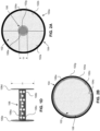
- FIG. 2A illustrates a cross-sectional view of an example fluid noise suppressor 100a.
- Fluid noise suppressor 100a can include the resilient insert 102, for example, including the first discrete resilient insert portion 102a, and the second resilient insert portion 102b configured such that each portion 102a, 102b can have a partially annular cross-section, which when configured to physically abut one another, form an annular cross-section.
- the channel 102g can have an inner diameter D2.
- the inner diameter D2 can be similar in dimension to an inner diameter of the upstream and/or downstream fluidic conduit 101a, 101b.
- the permeable tube 106a can be surrounded by the inner surface 102c resilient insert 102.
- FIG. 2B illustrates a cross-sectional view of an example fluid noise suppressor.
- the permeable tube 106a i.e. permeable cage
- the channel 102g can be defined between the inner surface 104a of the outer shell 104, and the outer surface 102c of the resilient insert 102.
- the resilient insert 102 can be centered within the outer shell 104 by utilizing the first and/or second flange 106d, 106e, of the restraining insert 106 and/or an integral restraining portion 104c.
- FIG. 3 illustrates an example method 300 for manufacturing an example in-line fluid noise suppressor.
- the method can include providing a resilient insert having an outer surface and an inner surface, the inner surface defining therethrough a channel for a fluid to flow along a length of the resilient insert, the resilient insert can be operable to dampen a fluctuation of a total pressure in the fluid that exceeds a mean static pressure, providing effective fluid-borne noise suppression that without the resilient insert, would have occurred in the flowing fluid with the fluctuation.
- the resilient insert can include a first discrete resilient insert portion and a second discrete resilient insert portion that can be operable to physically abut one another, preventing radial compression of the resilient insert that may lead to ineffective fluid-borne noise reduction.
- the resilient insert can have a substantially annular cross-section. Additionally or alternatively, the several discrete resilient insert portion can have a partially annular cross-section. Additionally or alternatively, first discrete resilient insert portion and second discrete resilient insert portion can be segmented axially.
- the method can include providing an outer shell extending along the outer surface of the resilient insert, the outer shell having an integral fluid connector, and an inner wall, the integral fluid connector disposed proximate an upstream end of the outer shell. Additionally or alternatively, the integral fluid connector disposed on an upstream end of the outer shell can be configured to provide fluid connectivity between an upstream portion of the channel and an upstream end of a fluidic conduit. Additionally or alternatively, the outer shell can include a restraining portion integral to the outer shell operable to restrain the resilient insert within the outer shell. At block 306, the method can include providing a restraining insert comprising a permeable tube operable to enable fluid communication between the outer surface of the resilient insert and the channel.
- the method can include providing a discrete fluid connector disposed on a downstream end of the outer shell. Additionally or alternatively, the discrete fluid connector disposed on a downstream end of the outer shell can be configured to provide fluid connectivity between a downstream portion of the channel and a downstream end of a fluidic conduit.
- the method can include inserting the restraining insert within the outer shell.
- the restraining insert can include at least one flange with an outer diameter and disposed on at least one end of the permeable tube, wherein the outer diameter of the flange can abut an inner surface of the outer shell, and the flange can be operable to restrain the resilient insert within the outer shell.
- the method can include inserting the resilient insert into the outer shell.
- the method can include attaching the discrete fluid connector to the downstream end of the outer shell.
- a fluid noise suppressor can include a foam material configured as a lining within a cylindrical pressure-containing shell, and with a central tube. However, under pressure, the cylinder of foam compresses radially, causing loading on the support tube, reduction of performance, and the potential to trap pressure.
- the foam material can be segmented into one or more axial segments, such that there need not be continuity of material in the circumferential direction prevents the radial compression of the foam, eliminating the behavior that impairs the performance.
- a fluid noise suppressor uses an axially segmented syntactic foam.
- the syntactic foam can be comprised of a host matrix (such as a urethane) with embedded microspheres.
- the microspheres can be charged with gas, at a pressure which may be above atmospheric pressure. Under pressure, the microspheres buckle, reducing the stiffness of the material, while retaining the gas itself.
- the high volume fraction of microspheres typically 50% yields a material with a fine-grained micro-structure, such that the host material also contributes compliance.
- the macroscopically segmented syntactic foam liner retains compliance to higher static pressure as compared to classical foams. The segmentation prevents pressure trapping and radial collapse of the liner, such that the fluid noise suppressor performs its intended function across varying system pressure.
Landscapes
- Engineering & Computer Science (AREA)
- General Engineering & Computer Science (AREA)
- Mechanical Engineering (AREA)
- Physics & Mathematics (AREA)
- Acoustics & Sound (AREA)
- Multimedia (AREA)
- Pipe Accessories (AREA)
- Reciprocating Pumps (AREA)
Description
- This application claims the benefit of
US Provisional Application No. 62/837,582, filed 23 April 2019 - The document
US 3103234 relates to devices for dampening pressure surges in fluid conduits, and more particularly, devices for absorbing, dampening or minimizing sudden surges or changes in pressure in fluid pipe lines. - The document
US 2003/0159743 A1 relates to an in-line type fluid hammer prevention device capable of maintaining pressure energy conversion efficiency of elastic cushion for a long time by improving fluid sealing tightness against an elastic cushion by elastic cylindrical diaphragm, wherein an inlet cylindrical connecting body and an outlet connecting body are connected at an intermediate position of fluid channel of a piping system in series, and both ends of a sleeve is positioned between center through-holes, and a cylindrical diaphragm is placed around the outer periphery side of small holes provided on the wall of the sleeve, and inward lip portions at the both ends of the cylindrical diaphragm are pressed and supported by the protrusive flanges and the recessed seats, and an elastic cushion is placed outside the cylindrical diaphragm around the outer periphery side of the small holes of the sleeve. - Noise in fluid systems is a common issue in industrial, commercial, and residential settings. Fluid-borne noise may be generated by the action of pumps, valves, and actuators, and just through the turbulent flow of liquids. Commercially available technology uses a pressurized gas bladder, with complex internals, to control noise. This device requires continual maintenance contact to maintain the gas charge; if the bladder fails, the device loses its noise control function. Additionally, the complex internals are costly.
- Thus, it would be advantageous to have a fluid noise suppressor that does not have moving parts and reduce the number and cost of replacements or repairs of a fluid noise suppressors device.
- It is an object of the present invention to provide systems, devices, and methods to meet the above-stated needs.
- According to the present invention there is provided a fluid system according to claim 1.
- The fluid noise suppressor includes an outer shell extending for a length of the outer surface of the resilient insert. In some examples, the fluid channel is defined between the outer surface of the resilient insert and an inner surface of the outer shell.
- In some examples, the fluid noise suppressor can further include a restraining portion integral to the outer shell and operable to restrain the resilient insert within the outer shell.
- In some examples, the resilient insert and the outer shell can be concentrically aligned.
- The fluid noise suppressor includes a permeable cage extending along the outer surface of the resilient insert and placed between the outer shell and the resilient insert.
- In some examples, the resilient insert can include an inner surface defining therethrough a channel for a fluid flowing along a length of the resilient insert having a mean static pressure.
- In some examples, the fluid system can further include an existing length of a fluidic conduit; wherein the fluid noise suppressor can be located between an upstream portion and downstream portion of the existing length of the fluidic conduit; and wherein the upstream portion of the existing length of the fluidic conduit, the fluid noise suppressor, and the downstream portion of the existing length of the fluidic conduit, can be in fluidic communication along the existing length of the portions and fluid noise suppressor.
- In some examples, the fluid noise suppressor system can include a fluid inlet connector disposed on an upstream end of the fluid noise suppressor providing both connectivity of the upstream end of the fluid noise suppressor to the upstream portion of the fluidic conduit and to inhibit travel of the resilient insert into the upstream portion of the fluidic conduit; and a fluid outlet connector disposed on a downstream end of the fluid noise suppressor providing both connectivity of the downstream end of the fluid noise suppressor to the downstream portion of the fluidic conduit and to inhibit travel of the resilient insert into the downstream portion of the fluidic conduit.
- In some examples, the resilient insert can include a first discrete resilient insert portion and a second discrete resilient insert portion that can be operable to physically abut one another, preventing radial compression of the resilient insert that would lead to ineffective noise reduction.
- In some examples, the resilient insert can include an annular cross-section; and wherein each of the discrete resilient insert portion includes a partially annular cross-section.
- In some examples, the resilient insert can be segmented axially to form the first discrete resilient insert portion and the second discrete resilient insert portion.
- The resilient insert includes a polymeric matrix having a stiffness; and microspheres dispersed within the polymeric matrix; wherein the microspheres are pressurized to a pressure of 0.1 MPa or grater. The stiffness of the polymeric matrix of at least one of the resilient inserts can be different from another of the resilient inserts.
- In some examples, each resilient insert portion can include a polymeric matrix having a stiffness; and microspheres dispersed within the polymeric matrix.
- The microspheres are pressurized to an internal pressure of 0.1 MPa or greater; and the microspheres can be homogeneously dispersed within the polymeric matrix.
- The microspheres are pressurized to an internal pressure of 0.1 MPa or greater; and the microspheres can be heterogeneously dispersed within the polymeric matrix.
- A fluid noise suppressor system is disclosed in claim 7.
- In some examples, the resilient insert can be segmented axially to form the first discrete resilient insert portion and the second discrete resilient insert portion.
- In some examples, the fluid noise suppressor system can further include a fluid inlet connector disposed on an upstream end of the fluid noise suppressor providing both connectivity of the upstream end of the fluid noise suppressor to the upstream portion of the fluidic conduit and to inhibit travel of the resilient insert into the upstream portion of the fluidic conduit; and a fluid outlet connector disposed on a downstream end of the fluid noise suppressor providing both connectivity of the downstream end of the fluid noise suppressor to the downstream portion of the fluidic conduit and to inhibit travel of the resilient insert into the downstream portion of the fluidic conduit.
- In some examples, the permeable tube comprising a flange located on least at one end of the permeable tube and operable to restrain the resilient insert within the outer shell.
- In some examples, the fluid noise suppressor system can further include a restraining portion integral to the outer shell and operable to restrain the resilient insert within the outer shell.
- In some examples, the fluid noise suppressor system can further include a flange with an outer diameter disposed on an end of the permeable tube; wherein the outer diameter of the flange can be sized to abut an inner surface of the outer shell; and wherein the flange can be operable to restrain the resilient insert within the length of the outer shell.
- In some examples, the fluid noise suppressor system can further include a restraining portion integral to the outer shell and operable to restrain the resilient insert within the outer shell.
- According to the present invention there is provided a method for manufacturing a fluid noise suppressor according to claim 11.
- In some examples, the restraining insert of the fluid noise suppressor can further include a flange with an outer diameter disposed on an end of the permeable tube, wherein the outer diameter of the flange can abut an inner surface of the outer shell, and the flange can be operable to restrain the resilient insert within the length of the outer shell.
- In some examples, the restraining insert of the fluid noise suppressor can further include a restraining portion integral to the outer shell operable to restrain the resilient insert within the outer shell.
- In some examples, the resilient insert can include a first discrete resilient insert portion and a second discrete resilient insert portion that can be operable to physically abut one another, preventing radial compression of the resilient insert that would lead to ineffective fluid noise reduction.
- In some examples, the resilient insert can include an annular cross-section; and wherein each of the discrete resilient insert portion can include a partially annular cross-section.
- In some examples, the resilient insert can be segmented axially to form the first discrete resilient insert portion and the second discrete resilient insert portion.
- Other implementations, features, and aspects are disclosed in the appended claims.
- Reference will now be made to the accompanying figures and flow diagrams, which are not necessarily drawn to scale.
-
FIGs. 1A-D illustrate an exploded view of an example fluid system, as disclosed herein. -
FIGs. 2A-B illustrates a cross-section view of an example fluid noise suppressor, as disclosed herein. -
FIG. 3 illustrates a method for manufacturing an example in-line fluid noise suppressor, as disclosed herein. - Some implementations of the disclosed technology will be described more fully hereinafter with reference to the accompanying drawings. This disclosed technology may, however, be embodied in many different forms and should not be construed as limited to the implementations set forth therein as long as it is covered by the appended claims.
- In the following description, numerous specific details are set forth. But it is to be understood that implementations of the disclosed technology may be practiced without these specific details. In other instances, well-known methods, structures, and techniques have not been shown in detail in order not to obscure an understanding of this description. References to "one implementation," "an implementation," "example implementation," "some implementations," "certain implementations," "various implementations," etc., indicate that the implementation(s) of the disclosed technology so described may include a particular feature, structure, or characteristic, but not every implementation necessarily includes the particular feature, structure, or characteristic. Further, repeated use of the phrase "in one implementation" does not necessarily refer to the same implementation, although it may.
- Throughout the specification and the claims, the following terms take at least the meanings explicitly associated herein, unless the context clearly dictates otherwise. The term "or" is intended to mean an inclusive "or." Further, the terms "a," "an," and "the" are intended to mean one or more unless specified otherwise or clear from the context to be directed to a singular form.
- Unless otherwise specified, the use of the ordinal adjectives "first," "second," "third," etc., to describe a common object, merely indicate that different instances of like objects are being referred to, and are not intended to imply that the objects so described should be in a given sequence, either temporally, spatially, in ranking, or in any other manner.
-
FIG. 1A illustrates afluid system 100. Thefluid system 100 can include afluid noise suppressor 100a, anupstream fluidic conduit 101a (i.e. an upstream portion of a fluidic conduit), and a downstreamfluidic conduit 101b (i.e. a downstream portion of a fluidic conduit). The upstream and downstreamfluidic conduits fluidic conduits fluidic conduits fluid noise suppressor 100a can include aresilient insert 102, anouter shell 104, a restraininginsert 106, afluid inlet connector 108, afluid outlet connector 110, anupstream end 112, and adownstream end 114. Thefluid noise suppressor 100a can be dimensioned, configured, and/or operable to comply with applicable regulatory codes such as codes published by the National Fluid Power Association (NFPA), American National Standards Institute (ANSI), Society of Automotive Engineers (SAE), or similar the regulatory entities. Each of thefluid conduits fluid noise suppressor 100a. - Turning to
FIG. 1B , theresilient insert 102 can be operable to dampen a fluctuation of a total pressure about the mean static pressure, providing effective noise reduction that without theresilient insert 102, would have occurred in the flowing fluid with the fluctuation. The mean static pressure is between about 100 psig to about 10,000 psig. Theresilient insert 102 is made of a polymeric matrix having a stiffness. The stiffness of the polymeric matrix can be similar to that of syntactic foam, as would be understood by one of skill in the art. The polymeric matrix can be, for example, a urethane or a silicone rubber. The polymeric matrix includes microspheres dispersed within the polymeric matrix. The microspheres have an internal pressure of 0.1 MPa or greater. The microspheres can be homogenously dispersed throughout the polymeric matrix. The microspheres can be heterogeneously dispersed throughout the polymeric matrix. Theresilient insert 102 can have cylindrical, cuboid, spherical, patterned and/or asymmetric shape. Theresilient insert 102 can have an annular, a solid, a honeycomb, and/or a cuboid cross-section. Additionally or alternatively, the cross-section of theresilient insert 102 can be asymmetric and/or patterned. Additionally or alternatively, theresilient insert 102 can be segmented into two or more discrete resilient insert portions, for example, a first discreteresilient insert portion 102a and a second discreteresilient insert portion 102b. Additionally, theresilient insert 102 can have a third discreteresilient insert portion 102e. The first discreteresilient insert portion 102a can physically abut the secondresilient insert portion 102b. Theresilient insert 102 can be segmented in a cross-sectional direction, axial direction, and/or in a diagonal direction. The segments can have curvilinear and/or linear cuts. Additionally or alternatively, the cuts to segment theresilient insert 102 into a first discreteresilient insert portion 102a and the second discreteresilient insert portion 102b can be along theouter surface 102c of theresilient insert 102. It may be advantageous to segment theresilient insert 102 along theouter surface 102c because the lack of direct connectivity between the first discreteresilient insert portion 102a and the secondresilient insert portion 102b may reduce compression in the radial direction of eachresilient insert portion resilient insert 102 can have a length L. - Additionally or alternatively, each discrete portion can different polymeric matrices, microsphere dispersion, microsphere internal pressures, and/or stiffnesses. It may be advantageous to have a polymeric matrix with dispersed pressurized microspheres because the polymeric matrix can absorb a portion of the pressure fluctuation and convert it into a mechanical displacement of the polymeric matrix. Additionally, the pressurized microspheres further absorb a portion of the pressure fluctuation by compressing under a pressure greater than their internal pressure. Further, common polymeric foam materials may not be mechanically robust enough for use in fluid noise suppressor devices. Additionally or alternatively, the
resilient insert 102 can include aninner surface 102d, theinner surface 102d can define therethrough achannel 102g for a fluid flowing along a length of theresilient insert 102. Theresilient insert 102 can include at least oneopening 102f that connects theouter surface 102c to theinner surface 102d. Additionally or alternatively, thechannel 102g can have afirst opening 102f connecting to theinner surface 102d, which can define a cavity. Additionally or alternatively, thechannel 102g can have a second opening operable to connect theouter surface 102c to theinner surface 102d. Additionally or alternatively, theouter surface 102c of theresilient insert 102 can define a channel between theouter surface 102c and theouter shell 104 for a fluid flowing along a length of theresilient insert 102, as will be discussed in detail inFIG. 2B . Additionally or alternatively, theresilient insert 102 can be concentrically aligned within theouter shell 104. Additionally, theresilient insert 102 can have a length L. - Turning to
FIG. 1C , theouter shell 104 can have aninner surface 104a and anopening 104b. Additionally or alternatively, theouter shell 104 can have a restrainingportion 104c integral to theouter shell 104 and operable to restrain theresilient insert 102 within theouter shell 104 to prevent clogging of thefluid outlet connector 110. The restrainingportion 104c can be one or more of: nubs, claws, protrusions, patterns, and/or diameter reducing mechanisms. Theouter shell 104 can be manufactured from plastics such as PVC, and/or metals such as copper, and can be operable to withstand pressures exceeding 100 psig. - Turning to
FIG. 1D , the restraininginsert 106 can include apermeable tube 106a having afirst end 106b and asecond end 106c. Thepermeable tube 106a (i.e. a permeable cage) can include holes, slots, and/or other perforation operable to allow fluid transfer to and from the resilient insert. Additionally or alternatively, thepermeable tube 106a can be a permeable membrane operable to allow fluids to diffuse into and out of theresilient insert 102. For example, thepermeable tube 106a can be at least partially surrounded by theresilient insert 102. In another example, thepermeable tube 106a can at least partially surround theresilient insert 102. Additionally or alternatively, thepermeable tube 106a can include afirst flange 106d on at least one of the first orsecond end first flange 106d can be operable to restrain theresilient insert 102 within theouter shell 104 keeping theresilient insert 102 from clogging thefluid outlet connector 110. Additionally or alternatively, thepermeable tube 106a can include asecond flange 106e on at least one of the first orsecond end second flange 106e can be operable to restrain theresilient insert 102 within theouter shell 104 keeping theresilient insert 102 from clogging thefluid inlet connector 108. At least one of the first ofsecond flanges outer shell 104. Theresilient insert 106 can be manufactured from plastics such as PVC, and/or metals such as copper. - Turning back to
FIG. 1A , thefluid inlet connector 108 can be disposed on anupstream end 112 of thefluid noise suppressor 100a providing both connectivity of theupstream end 112 of thefluid noise suppressor 100a to the upstreamfluidic conduit 101a and to inhibit travel of theresilient insert 102 into the upstreamfluidic conduit 101a. Thefluid inlet connector 108 can include a threaded portion configured to receive the upstreamfluidic conduit 101a. One of skill in the art would appreciate that the threads can comply with existing standards for pipe threads, for example, American National Standard Pipe thread (NPT) standards. Additionally or alternatively, thefluid inlet connector 108 can have a custom thread and/or fitting depending on the application. Thefluid inlet connector 108 can be manufactured from metals and/or plastics. Additionally or alternatively, thefluid inlet connector 108 can be integral to theouter shell 104. Additionally or alternatively, thefluid inlet connector 108 can be discrete to theouter shell 104. - The fluid outlet connector 110 (i.e. fluid connector) can be disposed on a
downstream end 114 of thefluid noise suppressor 100a providing both connectivity of thedownstream end 114 of thefluid noise suppressor 100a to the downstreamfluidic conduit 101b and to inhibit travel of theresilient insert 102 into the downstreamfluidic conduit 101b. Thefluid outlet connector 110 can include a threaded portion configured to receive the downstreamfluidic conduit 101b. One of skill in the art would appreciate that the threads can comply with existing standards for pipe threads, for example, American National Standard Pipe thread (NPT) standards. Additionally or alternatively, thefluid outlet connector 110 can have a custom thread and/or fitting depending on the application. Thefluid outlet connector 110 can be manufactured from metals and/or plastics. Additionally or alternatively, thefluid outlet connector 110 can be integral to theouter shell 104. Additionally or alternatively, thefluid outlet connector 110 can be discrete to theouter shell 104. -
FIG. 2A illustrates a cross-sectional view of an examplefluid noise suppressor 100a.Fluid noise suppressor 100a can include theresilient insert 102, for example, including the first discreteresilient insert portion 102a, and the secondresilient insert portion 102b configured such that eachportion channel 102g can have an inner diameter D2. The inner diameter D2 can be similar in dimension to an inner diameter of the upstream and/or downstreamfluidic conduit permeable tube 106a can be surrounded by theinner surface 102cresilient insert 102. -
FIG. 2B illustrates a cross-sectional view of an example fluid noise suppressor. Thepermeable tube 106a (i.e. permeable cage) can surround theouter surface 102c of theresilient insert 102. Thechannel 102g can be defined between theinner surface 104a of theouter shell 104, and theouter surface 102c of theresilient insert 102. Theresilient insert 102 can be centered within theouter shell 104 by utilizing the first and/orsecond flange insert 106 and/or anintegral restraining portion 104c. -
FIG. 3 illustrates anexample method 300 for manufacturing an example in-line fluid noise suppressor. Atblock 302, the method can include providing a resilient insert having an outer surface and an inner surface, the inner surface defining therethrough a channel for a fluid to flow along a length of the resilient insert, the resilient insert can be operable to dampen a fluctuation of a total pressure in the fluid that exceeds a mean static pressure, providing effective fluid-borne noise suppression that without the resilient insert, would have occurred in the flowing fluid with the fluctuation. Additionally or alternatively, the resilient insert can include a first discrete resilient insert portion and a second discrete resilient insert portion that can be operable to physically abut one another, preventing radial compression of the resilient insert that may lead to ineffective fluid-borne noise reduction. Additionally or alternatively, the resilient insert can have a substantially annular cross-section. Additionally or alternatively, the several discrete resilient insert portion can have a partially annular cross-section. Additionally or alternatively, first discrete resilient insert portion and second discrete resilient insert portion can be segmented axially. - At
block 304, the method can include providing an outer shell extending along the outer surface of the resilient insert, the outer shell having an integral fluid connector, and an inner wall, the integral fluid connector disposed proximate an upstream end of the outer shell. Additionally or alternatively, the integral fluid connector disposed on an upstream end of the outer shell can be configured to provide fluid connectivity between an upstream portion of the channel and an upstream end of a fluidic conduit. Additionally or alternatively, the outer shell can include a restraining portion integral to the outer shell operable to restrain the resilient insert within the outer shell. Atblock 306, the method can include providing a restraining insert comprising a permeable tube operable to enable fluid communication between the outer surface of the resilient insert and the channel. Atblock 308, the method can include providing a discrete fluid connector disposed on a downstream end of the outer shell. Additionally or alternatively, the discrete fluid connector disposed on a downstream end of the outer shell can be configured to provide fluid connectivity between a downstream portion of the channel and a downstream end of a fluidic conduit. - At
block 310, the method can include inserting the restraining insert within the outer shell. Additionally or alternatively, the restraining insert can include at least one flange with an outer diameter and disposed on at least one end of the permeable tube, wherein the outer diameter of the flange can abut an inner surface of the outer shell, and the flange can be operable to restrain the resilient insert within the outer shell. Atblock 312, the method can include inserting the resilient insert into the outer shell. Atblock 314, the method can include attaching the discrete fluid connector to the downstream end of the outer shell. - In an example, a fluid noise suppressor can include a foam material configured as a lining within a cylindrical pressure-containing shell, and with a central tube. However, under pressure, the cylinder of foam compresses radially, causing loading on the support tube, reduction of performance, and the potential to trap pressure. The foam material can be segmented into one or more axial segments, such that there need not be continuity of material in the circumferential direction prevents the radial compression of the foam, eliminating the behavior that impairs the performance.
- In an example, a fluid noise suppressor uses an axially segmented syntactic foam. The syntactic foam can be comprised of a host matrix (such as a urethane) with embedded microspheres. The microspheres can be charged with gas, at a pressure which may be above atmospheric pressure. Under pressure, the microspheres buckle, reducing the stiffness of the material, while retaining the gas itself. In addition, the high volume fraction of microspheres (typically 50%) yields a material with a fine-grained micro-structure, such that the host material also contributes compliance. In concert, the macroscopically segmented syntactic foam liner retains compliance to higher static pressure as compared to classical foams. The segmentation prevents pressure trapping and radial collapse of the liner, such that the fluid noise suppressor performs its intended function across varying system pressure.
- While certain techniques and methods of the disclosed technology have been described in connection with what is presently considered to be the most practical implementations, it is to be understood that the disclosed technology is not to be limited to the disclosed implementations, but on the contrary, is intended to cover various modifications and equivalent arrangements as long as they are included within the scope of the appended claims. Although specific terms are employed herein, they are used in a generic and descriptive sense only and not for purposes of limitation.
- This written description uses examples to disclose certain implementations of the disclosed technology, including the best mode, and also to enable any person skilled in the art to practice certain implementations of the disclosed technology, including making and using any devices or systems and performing any incorporated methods. The patentable scope of certain implementations of the disclosed technology is defined in the claims.
Claims (11)
- A fluid system (100) comprising:
a fluid noise suppressor (100a) comprising:a resilient insert (102) having an outer surface (102c) and comprising a polymeric matrix having a stiffness and microspheres dispersed within the polymeric matrix, wherein the microspheres are pressurized to a pressure of 0.1 MPa or greater, wherein the polymeric matrix with microspheres dispersed therein enable the resilient insert to be operable to dampen a fluctuation in a flowing fluid of a total pressure about a mean static pressure between about 689 kPa to about 69 MPa, providing effective noise reduction that without the resilient insert, would have occurred in the flowing fluid with the fluctuation;an outer shell (104) extending for a length of the outer surface (102c) of the resilient insert (102);a permeable cage (106a) extending along the outer surface (102c) of the resilient insert (102) and positioned between the outer shell (104) and the resilient insert (102); anda fluid channel (102g) providing fluid connectivity of the flowing fluid through the fluid system (100). - The fluid system (100) of Claim 1, wherein:- the fluid channel (102g) is defined between the outer surface (102c) of the resilient insert (102) and an inner surface (104a) of the outer shell (104), and/or- the fluid noise suppressor (100a) further comprises a restraining portion (104c) integral to the outer shell (104) and operable to restrain the resilient insert (102) within the outer shell (104).
- The fluid system (100) of Claim 1, wherein the resilient insert (102) and the outer shell (104) are concentrically aligned.
- The fluid system (100) of Claim 1, wherein one or more of:- the resilient insert (102) further has an inner surface (102d) defining therethrough the fluid channel (102g),- the resilient insert (102) comprises a first discrete resilient insert portion (102a) and a second discrete resilient insert portion (102b) that are operable to physically abut one another, preventing radial compression of the resilient insert (102) that would lead to ineffective noise reduction,- the resilient insert (102) comprises a first discrete resilient insert portion (102a) and a second discrete resilient insert portion (102b) that are operable to physically abut one another, preventing radial compression of the resilient insert (102) that would lead to ineffective noise reduction, and the stiffness of the polymeric matrix of at least one of the discrete resilient insert portions (102a, 102b) is different from another of the discrete resilient insert portions (102a, 102b), and/or- the resilient insert (102) comprises a first discrete resilient insert portion (102a) and a second discrete resilient insert portion (102b) that are operable to physically abut one another, preventing radial compression of the resilient insert (102) that would lead to ineffective noise reduction, and the microspheres are homogeneously or heterogeneously dispersed within the polymeric matrix.
- The fluid system (100) of Claim 1 further comprising an existing length of a fluidic conduit (101a, 101b);wherein the fluid noise suppressor (100a) is located between an upstream portion (101a) and downstream portion (101b) of the existing length of the fluidic conduit;wherein the upstream portion (101a) of the existing length of the fluidic conduit, the fluid noise suppressor (100a), and the downstream portion (101b) of the existing length of the fluidic conduit, are in fluidic communication along the existing length of the portions and fluid noise suppressor (100a); andwherein the noise suppressor (100a) further comprises:a fluid inlet connector (108) disposed on an upstream end (112) of the fluid noise suppressor (100a) providing both connectivity of the upstream end (112) of the fluid noise suppressor (100a) to the upstream portion (101a) of the fluidic conduit and to inhibit travel of the resilient insert (102) into the upstream portion (101a) of the fluidic conduit; anda fluid outlet connector (110) disposed on a downstream end (114) of the fluid noise suppressor (100a) providing both connectivity of the downstream end (114) of the fluid noise suppressor (100a) to the downstream portion (101b) of the fluidic conduit and to inhibit travel of the resilient insert (102) into the downstream portion (101b) of the fluidic conduit.
- The fluid system of Claim 1, wherein the resilient insert (102) comprises a first discrete resilient insert portion (102a) and a second discrete resilient insert portion (102b) that are operable to physically abut one another, preventing radial compression of the resilient insert (102) that would lead to ineffective noise reduction; and
wherein the resilient insert:further has an annular cross-section and each of the discrete resilient insert portions (102a, 102b) comprise a partially annular cross-section, and/oris segmented axially to form the first discrete resilient insert portion (102a) and the second discrete resilient insert portion (102b). - A fluid noise suppressor system comprising:an upstream portion (101a) of a fluidic conduit;the fluid system (100) of claim 1 located downstream of the upstream portion (101a) of the fluidic conduit; anda downstream portion (101b) of the fluidic conduit being located downstream of the fluid system (100);wherein the resilient insert (102) comprises a first discrete resilient insert portion (102a) and a second discrete resilient insert portion (102b) that are operable to physically abut one another, preventing radial compression of the resilient insert (102) that would lead to ineffective noise reduction;wherein the resilient insert (102) further has:an inner surface (102d) defining therethrough the fluid channel (102g) having an inner diameter (D2) substantially similar to an inner diameter of the upstream and downstream portions (101a, 101b) of the fluidic conduit, andan annular cross-section such that each of the two discrete resilient insert portions (102a, 102b) comprises a partially annular cross-section; andwherein the fluid noise suppressor (100a) and the portions (101a, 101b) of the fluidic conduit are configured for the flowing fluid within each having the mean static pressure.
- The fluid noise suppressor system of Claim 7, wherein the resilient insert (102) is segmented axially to form the discrete resilient insert portions (102a, 102b).
- The fluid noise suppressor system of Claim 7, further comprising:a fluid inlet connector (108) disposed on an upstream end (112) of the fluid noise suppressor (100a) providing both connectivity of the upstream end (112) of the fluid noise suppressor (100a) to the upstream portion (101a) of the fluidic conduit and to inhibit travel of the resilient insert (102) into the upstream portion (101a) of the fluidic conduit; anda fluid outlet connector (110) disposed on a downstream end (114) of the fluid noise suppressor (100a) providing both connectivity of the downstream end (114) of the fluid noise suppressor (100a) to the downstream portion (101b) of the fluidic conduit and to inhibit travel of the resilient insert (102) into the downstream portion (101b) of the fluidic conduit;wherein the permeable cage (106a) further extends for a length of the inner surface (102d) of the resilient insert (102) and is operable to enable fluidic communication from the fluid inlet connector (108) through the fluid outlet connector (110); andwherein the permeable cage (106a) further comprises a flange (106d, 106e) located on at least one end (106b, 106c) of the permeable cage (106a) and operable to restrain the resilient insert (102) within the outer shell (104).
- The fluid noise suppressor system of Claim 9 further comprising a restraining portion (104c) integral to the outer shell (104) and operable to restrain the resilient insert (102) within the outer shell (104).
- A method for manufacturing a fluid noise suppressor (100a) comprising:providing a resilient insert (102) having an outer surface (102c) and an inner surface (102d), the inner surface (102d) defining therethrough a fluid channel (102g) for a fluid flowing along a length of the resilient insert (102), the resilient insert comprising a polymeric matrix having a stiffness and microspheres dispersed within the polymeric matrix, wherein the microspheres are pressurized to a pressure of 0.1 MPa or greater, wherein the polymeric matrix with microspheres dispersed therein enable the resilient insert to be operable to dampen a fluctuation of a total pressure in the fluid that exceeds a mean static pressure between about 689 kPa to about 69 MPa, providing effective fluid-borne noise suppression that without the resilient insert (102), would have occurred in the flowing fluid with the fluctuation;providing an outer shell (104) extending along the outer surface (102c) of the resilient insert (102), the outer shell (104) having a fluid inlet connector (108) integral therewith, and an inner surface (104a), the integral inlet fluid connector (108) disposed on a upstream end of the outer shell (104) configured to provide fluid connectivity between a upstream portion of the fluid channel (102g) and an upstream portion (101a) of a fluidic conduit;providing a restraining insert (106) comprising a permeable tube (106a) operable to enable fluidic communication through the fluid channel (102g);providing a discrete fluid outlet connector (110) disposed on a downstream end of the outer shell (104) and configured to provide fluid connectivity between a downstream portion of the fluid channel (102g) and a downstream portion (101b) of the fluidic conduit;inserting the restraining insert 106) radially within the resilient insert (102);inserting the resilient insert (102) radially into the outer shell (104); andattaching the discrete fluid outlet connector (110) to the downstream end of the outer shell (104).
Applications Claiming Priority (2)
| Application Number | Priority Date | Filing Date | Title |
|---|---|---|---|
| US201962837582P | 2019-04-23 | 2019-04-23 | |
| PCT/US2020/029526 WO2020219678A2 (en) | 2019-04-23 | 2020-04-23 | Systems and methods for a fluid noise suppressor |
Publications (4)
| Publication Number | Publication Date |
|---|---|
| EP3942214A2 EP3942214A2 (en) | 2022-01-26 |
| EP3942214A4 EP3942214A4 (en) | 2022-11-30 |
| EP3942214C0 EP3942214C0 (en) | 2024-10-09 |
| EP3942214B1 true EP3942214B1 (en) | 2024-10-09 |
Family
ID=72941267
Family Applications (2)
| Application Number | Title | Priority Date | Filing Date |
|---|---|---|---|
| EP20796236.6A Withdrawn EP3956597A4 (en) | 2019-04-23 | 2020-04-23 | SYSTEMS AND METHODS FOR A WATER HAMMER ARRESTOR |
| EP20794874.6A Active EP3942214B1 (en) | 2019-04-23 | 2020-04-23 | Systems and methods for a fluid noise suppressor |
Family Applications Before (1)
| Application Number | Title | Priority Date | Filing Date |
|---|---|---|---|
| EP20796236.6A Withdrawn EP3956597A4 (en) | 2019-04-23 | 2020-04-23 | SYSTEMS AND METHODS FOR A WATER HAMMER ARRESTOR |
Country Status (7)
| Country | Link |
|---|---|
| US (2) | US20220146034A1 (en) |
| EP (2) | EP3956597A4 (en) |
| JP (2) | JP2022531120A (en) |
| CN (2) | CN114008367A (en) |
| CA (2) | CA3136829A1 (en) |
| MX (2) | MX2021012999A (en) |
| WO (2) | WO2020219676A1 (en) |
Families Citing this family (2)
| Publication number | Priority date | Publication date | Assignee | Title |
|---|---|---|---|---|
| MX2021012999A (en) * | 2019-04-23 | 2022-03-11 | Georgia Tech Res Inst | Systems and methods for a fluid noise suppressor. |
| CN118998497B (en) * | 2024-10-25 | 2025-01-24 | 西南石油大学 | A high-pressure oil pipe water hammer eliminator |
Family Cites Families (43)
| Publication number | Priority date | Publication date | Assignee | Title |
|---|---|---|---|---|
| US2495693A (en) * | 1946-03-26 | 1950-01-31 | Jr William Byrd | Hydraulic surge damper |
| US2918090A (en) * | 1955-12-29 | 1959-12-22 | Westinghouse Air Brake Co | Fluid pressure shock dampening device and resilient sleeve means for use therein |
| US2875788A (en) * | 1956-02-27 | 1959-03-03 | Westinghouse Air Brake Co | Pulsation dampener device |
| US2918091A (en) * | 1958-01-15 | 1959-12-22 | Toledo Scale Corp | Hydraulic dampeners |
| US3103234A (en) * | 1961-02-08 | 1963-09-10 | Beloit Iron Works | Fluid flow surge dampening system |
| US3665967A (en) * | 1970-01-16 | 1972-05-30 | Western Co Of North America | Supercharge hose |
| US4314621A (en) * | 1979-03-07 | 1982-02-09 | Caterpillar Tractor Co. | Fluidborne noise attenuator |
| US4497388A (en) * | 1981-08-25 | 1985-02-05 | Gaulin Corporation | Pulsation dampener and acoustic attenuator |
| US4580656A (en) * | 1984-04-06 | 1986-04-08 | Sankei Giken Kogyo Kabushiki Kaisha | Absorbent retainer for absorbent type muffler |
| US4897906A (en) * | 1987-11-02 | 1990-02-06 | Proprietary Technology, Inc. | Method of making a fluid pressure surge damper for a fluid system |
| FR2738326A1 (en) * | 1988-07-28 | 1997-03-07 | Bertin & Cie | Acoustic shock attenuator for hydraulic pressure lines |
| JP3211553B2 (en) * | 1994-04-28 | 2001-09-25 | 豊田合成株式会社 | Intake hose |
| US5777947A (en) * | 1995-03-27 | 1998-07-07 | Georgia Tech Research Corporation | Apparatuses and methods for sound absorption using hollow beads loosely contained in an enclosure |
| JPH08326986A (en) * | 1995-03-30 | 1996-12-10 | Inax Corp | Water hammer absorbing device |
| US5926954A (en) * | 1997-09-10 | 1999-07-27 | Acoust-A-Fiber Research & Development, Inc. | Method of making a silencer |
| KR100303125B1 (en) * | 1998-05-22 | 2001-11-30 | 광 진 박 | Method for manufacturing housing of hydraulic shock absorbing device |
| EP1002984A3 (en) * | 1998-11-21 | 2000-12-13 | Frey, Conrad | Water hammer and noise attenuator for water pipes and taps |
| JP2002206689A (en) * | 2000-11-24 | 2002-07-26 | Suzuki Sogyo Co Ltd | Piping in-series type liquid hammer preventing unit |
| US6539976B1 (en) * | 2002-03-15 | 2003-04-01 | Mifab, Inc. | Water hammer arrester |
| DE50202054D1 (en) * | 2002-09-09 | 2005-02-24 | Frey Konrad | Pressure hammer and noise damper, especially for connections of sanitary fittings |
| US20050042437A1 (en) * | 2003-08-19 | 2005-02-24 | Cryovac, Inc. | Sound dampening foam |
| US6948479B1 (en) * | 2004-09-01 | 2005-09-27 | Delphi Technologies, Inc. | Inline pulsation damper system |
| US20060124385A1 (en) * | 2004-12-10 | 2006-06-15 | Ingersoll-Rand Company | Modular pressure pulsation dampener |
| US7476056B2 (en) * | 2006-06-22 | 2009-01-13 | Gunderboom, Inc. | Sound attenuating sleeve for use on a piling |
| FR2903110B1 (en) * | 2006-06-29 | 2010-08-27 | Rech S Et De Controle Du Caout | MULTIPHASIC MIXTURE BASED ON GRANULATES OF ELASTOMERS CROSSLINKED IN POLYMERIC MATRIX WITH THERMOPLASTIC TRANSFORMATION |
| US20080185220A1 (en) * | 2006-11-14 | 2008-08-07 | Caterpillar Inc. | Method of using syntactic foam to reduce noise and machine using same |
| US7562678B1 (en) * | 2007-05-18 | 2009-07-21 | Vadim Gennadyevich Kulikov | Pipeline pressure stabilizer |
| US7874317B1 (en) * | 2007-05-18 | 2011-01-25 | Vadim Gennadyevich Kulikov | Micro pipeline pressure stabilization apparatus |
| DE102007045266A1 (en) * | 2007-09-21 | 2009-04-02 | Hydac Technology Gmbh | Damping device, in particular pulsation damper |
| JP2010236537A (en) * | 2009-03-10 | 2010-10-21 | Shinko Metal Products Kk | Laminated composite tube |
| US8307855B2 (en) * | 2009-07-07 | 2012-11-13 | King Saud University | Fluid pressure spike suppression device |
| CN201753815U (en) * | 2010-07-27 | 2011-03-02 | 江森自控空调冷冻设备(无锡)有限公司 | Three-way structure |
| US8939177B2 (en) * | 2013-03-15 | 2015-01-27 | Lsp Products Group, Inc. | In-line water hammer arrester |
| US20160075891A1 (en) * | 2014-09-16 | 2016-03-17 | Eastman Chemical Company | Polymeric compositions with improved noise suppression |
| US20160075858A1 (en) * | 2014-09-16 | 2016-03-17 | Eastman Chemical Company | Polymeric compositions with improved noise suppression |
| US10418016B2 (en) * | 2015-05-29 | 2019-09-17 | Staton Techiya, Llc | Methods and devices for attenuating sound in a conduit or chamber |
| EP3314083B1 (en) * | 2015-06-26 | 2020-12-09 | Amog Technologies PTY Ltd | A flow modification device, system, and method |
| FR3047347B1 (en) * | 2016-02-02 | 2018-02-02 | Fcd | SOUND WAVE ABSORPTION MODULE AND DEVICE COMPRISING SAME |
| CN205606072U (en) * | 2016-05-16 | 2016-09-28 | 艾欧史密斯(中国)热水器有限公司 | Liquid flow damping device |
| CN207094040U (en) * | 2017-02-03 | 2018-03-13 | 北京华德创业环保设备有限公司 | Through-type pulsation flow straightener |
| CA2965249A1 (en) * | 2017-04-24 | 2018-10-24 | Baum Pneumatics Inc. | Dampener for a fluid accelerator such as a pneumatic blower |
| CN107191732A (en) * | 2017-07-11 | 2017-09-22 | 新疆水利水电科学研究院 | Buffer unit and buffer system |
| MX2021012999A (en) * | 2019-04-23 | 2022-03-11 | Georgia Tech Res Inst | Systems and methods for a fluid noise suppressor. |
-
2020
- 2020-04-23 MX MX2021012999A patent/MX2021012999A/en unknown
- 2020-04-23 EP EP20796236.6A patent/EP3956597A4/en not_active Withdrawn
- 2020-04-23 CN CN202080030556.9A patent/CN114008367A/en active Pending
- 2020-04-23 WO PCT/US2020/029523 patent/WO2020219676A1/en not_active Ceased
- 2020-04-23 CA CA3136829A patent/CA3136829A1/en active Pending
- 2020-04-23 JP JP2021562792A patent/JP2022531120A/en active Pending
- 2020-04-23 JP JP2021562791A patent/JP2022531119A/en active Pending
- 2020-04-23 CA CA3136830A patent/CA3136830A1/en active Pending
- 2020-04-23 EP EP20794874.6A patent/EP3942214B1/en active Active
- 2020-04-23 CN CN202080030564.3A patent/CN114008368A/en active Pending
- 2020-04-23 US US17/605,963 patent/US20220146034A1/en not_active Abandoned
- 2020-04-23 US US17/605,987 patent/US12117116B2/en active Active
- 2020-04-23 MX MX2021012998A patent/MX2021012998A/en unknown
- 2020-04-23 WO PCT/US2020/029526 patent/WO2020219678A2/en not_active Ceased
Also Published As
| Publication number | Publication date |
|---|---|
| WO2020219678A3 (en) | 2021-04-22 |
| CN114008367A (en) | 2022-02-01 |
| EP3942214C0 (en) | 2024-10-09 |
| JP2022531120A (en) | 2022-07-06 |
| US12117116B2 (en) | 2024-10-15 |
| WO2020219678A2 (en) | 2020-10-29 |
| EP3956597A1 (en) | 2022-02-23 |
| CA3136829A1 (en) | 2020-10-29 |
| MX2021012998A (en) | 2022-03-11 |
| US20220146034A1 (en) | 2022-05-12 |
| EP3942214A2 (en) | 2022-01-26 |
| EP3956597A4 (en) | 2023-01-18 |
| MX2021012999A (en) | 2022-03-11 |
| CA3136830A1 (en) | 2020-10-29 |
| US20220196197A1 (en) | 2022-06-23 |
| EP3942214A4 (en) | 2022-11-30 |
| WO2020219676A1 (en) | 2020-10-29 |
| JP2022531119A (en) | 2022-07-06 |
| CN114008368A (en) | 2022-02-01 |
Similar Documents
| Publication | Publication Date | Title |
|---|---|---|
| US3473565A (en) | Shock absorber for liquid flow lines | |
| US3744527A (en) | Pulse damper unit for hydraulic system | |
| US12117116B2 (en) | Systems and methods for a fluid noise suppressor | |
| KR20240114776A (en) | Integrated One Way Valve | |
| US9506432B2 (en) | Sealing device | |
| EP2510272B1 (en) | Tube with an improved connection preferably for an air conditioning system | |
| AU2012208960B2 (en) | Water hammer arrester | |
| CN108180297B (en) | Anti-chatter check valve | |
| US6478052B1 (en) | Pulsation damping assembly and method | |
| JP6516710B2 (en) | Multiple eccentric type butterfly valve | |
| EP2390541A1 (en) | Ball valve device and method for forming a ball retainer in a check valve | |
| CN112555454B (en) | Bypass valve and fluid pipeline structure | |
| CN116292525A (en) | A pressure pulse mitigation device | |
| EP0193077A1 (en) | Non-pressurized surge arrestor for use in pipeline systems for dissipating the harmful effects of pressure surges and shock waves | |
| CN109780445B (en) | High-pressure air source device | |
| US12031659B2 (en) | Stabilizer cartridge | |
| CN219712691U (en) | Vibration isolation and noise elimination connector for pipeline | |
| CN220792086U (en) | Pistons, piston assemblies, solenoid valves, thermal management systems and vehicles | |
| RU2258172C1 (en) | Pressure stabilizer | |
| CN211315235U (en) | Check valve convenient to installation | |
| EP3683485B1 (en) | Damper for reducing pulsation of a fluid flow | |
| CN120175700A (en) | A miniature cartridge type precision hydraulic one-way valve | |
| CN121408309A (en) | A combination valve |
Legal Events
| Date | Code | Title | Description |
|---|---|---|---|
| STAA | Information on the status of an ep patent application or granted ep patent |
Free format text: STATUS: THE INTERNATIONAL PUBLICATION HAS BEEN MADE |
|
| PUAI | Public reference made under article 153(3) epc to a published international application that has entered the european phase |
Free format text: ORIGINAL CODE: 0009012 |
|
| STAA | Information on the status of an ep patent application or granted ep patent |
Free format text: STATUS: REQUEST FOR EXAMINATION WAS MADE |
|
| 17P | Request for examination filed |
Effective date: 20211020 |
|
| AK | Designated contracting states |
Kind code of ref document: A2 Designated state(s): AL AT BE BG CH CY CZ DE DK EE ES FI FR GB GR HR HU IE IS IT LI LT LU LV MC MK MT NL NO PL PT RO RS SE SI SK SM TR |
|
| DAV | Request for validation of the european patent (deleted) | ||
| DAX | Request for extension of the european patent (deleted) | ||
| A4 | Supplementary search report drawn up and despatched |
Effective date: 20221027 |
|
| RIC1 | Information provided on ipc code assigned before grant |
Ipc: F16L 55/033 20060101ALI20221021BHEP Ipc: F16L 55/045 20060101ALI20221021BHEP Ipc: F16L 55/04 20060101AFI20221021BHEP |
|
| P01 | Opt-out of the competence of the unified patent court (upc) registered |
Effective date: 20230418 |
|
| REG | Reference to a national code |
Ref country code: DE Free format text: PREVIOUS MAIN CLASS: F16L0055040000 Ipc: F16L0055050000 Ref country code: DE Ref legal event code: R079 Ref document number: 602020039194 Country of ref document: DE Free format text: PREVIOUS MAIN CLASS: F16L0055040000 Ipc: F16L0055050000 |
|
| GRAP | Despatch of communication of intention to grant a patent |
Free format text: ORIGINAL CODE: EPIDOSNIGR1 |
|
| STAA | Information on the status of an ep patent application or granted ep patent |
Free format text: STATUS: GRANT OF PATENT IS INTENDED |
|
| RIC1 | Information provided on ipc code assigned before grant |
Ipc: F16L 55/033 20060101ALI20240424BHEP Ipc: F16L 55/05 20060101AFI20240424BHEP |
|
| INTG | Intention to grant announced |
Effective date: 20240513 |
|
| RIN1 | Information on inventor provided before grant (corrected) |
Inventor name: PEDIGO, NATHANIEL R. Inventor name: CUNEFARE, KENNETH A. |
|
| GRAS | Grant fee paid |
Free format text: ORIGINAL CODE: EPIDOSNIGR3 |
|
| GRAA | (expected) grant |
Free format text: ORIGINAL CODE: 0009210 |
|
| STAA | Information on the status of an ep patent application or granted ep patent |
Free format text: STATUS: THE PATENT HAS BEEN GRANTED |
|
| AK | Designated contracting states |
Kind code of ref document: B1 Designated state(s): AL AT BE BG CH CY CZ DE DK EE ES FI FR GB GR HR HU IE IS IT LI LT LU LV MC MK MT NL NO PL PT RO RS SE SI SK SM TR |
|
| REG | Reference to a national code |
Ref country code: CH Ref legal event code: EP |
|
| REG | Reference to a national code |
Ref country code: DE Ref legal event code: R096 Ref document number: 602020039194 Country of ref document: DE |
|
| REG | Reference to a national code |
Ref country code: IE Ref legal event code: FG4D |
|
| U01 | Request for unitary effect filed |
Effective date: 20241018 |
|
| P04 | Withdrawal of opt-out of the competence of the unified patent court (upc) registered |
Free format text: CASE NUMBER: APP_59069/2024 Effective date: 20241030 |
|
| U07 | Unitary effect registered |
Designated state(s): AT BE BG DE DK EE FI FR IT LT LU LV MT NL PT RO SE SI Effective date: 20241104 |
|
| PG25 | Lapsed in a contracting state [announced via postgrant information from national office to epo] |
Ref country code: HR Free format text: LAPSE BECAUSE OF FAILURE TO SUBMIT A TRANSLATION OF THE DESCRIPTION OR TO PAY THE FEE WITHIN THE PRESCRIBED TIME-LIMIT Effective date: 20241009 Ref country code: IS Free format text: LAPSE BECAUSE OF FAILURE TO SUBMIT A TRANSLATION OF THE DESCRIPTION OR TO PAY THE FEE WITHIN THE PRESCRIBED TIME-LIMIT Effective date: 20250209 |
|
| PG25 | Lapsed in a contracting state [announced via postgrant information from national office to epo] |
Ref country code: ES Free format text: LAPSE BECAUSE OF FAILURE TO SUBMIT A TRANSLATION OF THE DESCRIPTION OR TO PAY THE FEE WITHIN THE PRESCRIBED TIME-LIMIT Effective date: 20241009 |
|
| PG25 | Lapsed in a contracting state [announced via postgrant information from national office to epo] |
Ref country code: GR Free format text: LAPSE BECAUSE OF FAILURE TO SUBMIT A TRANSLATION OF THE DESCRIPTION OR TO PAY THE FEE WITHIN THE PRESCRIBED TIME-LIMIT Effective date: 20250110 |
|
| PG25 | Lapsed in a contracting state [announced via postgrant information from national office to epo] |
Ref country code: PL Free format text: LAPSE BECAUSE OF FAILURE TO SUBMIT A TRANSLATION OF THE DESCRIPTION OR TO PAY THE FEE WITHIN THE PRESCRIBED TIME-LIMIT Effective date: 20241009 |
|
| PG25 | Lapsed in a contracting state [announced via postgrant information from national office to epo] |
Ref country code: RS Free format text: LAPSE BECAUSE OF FAILURE TO SUBMIT A TRANSLATION OF THE DESCRIPTION OR TO PAY THE FEE WITHIN THE PRESCRIBED TIME-LIMIT Effective date: 20250109 |
|
| PG25 | Lapsed in a contracting state [announced via postgrant information from national office to epo] |
Ref country code: SM Free format text: LAPSE BECAUSE OF FAILURE TO SUBMIT A TRANSLATION OF THE DESCRIPTION OR TO PAY THE FEE WITHIN THE PRESCRIBED TIME-LIMIT Effective date: 20241009 |
|
| PGFP | Annual fee paid to national office [announced via postgrant information from national office to epo] |
Ref country code: GB Payment date: 20250425 Year of fee payment: 6 |
|
| PGFP | Annual fee paid to national office [announced via postgrant information from national office to epo] |
Ref country code: NO Payment date: 20250429 Year of fee payment: 6 |
|
| PG25 | Lapsed in a contracting state [announced via postgrant information from national office to epo] |
Ref country code: SK Free format text: LAPSE BECAUSE OF FAILURE TO SUBMIT A TRANSLATION OF THE DESCRIPTION OR TO PAY THE FEE WITHIN THE PRESCRIBED TIME-LIMIT Effective date: 20241009 |
|
| PG25 | Lapsed in a contracting state [announced via postgrant information from national office to epo] |
Ref country code: CZ Free format text: LAPSE BECAUSE OF FAILURE TO SUBMIT A TRANSLATION OF THE DESCRIPTION OR TO PAY THE FEE WITHIN THE PRESCRIBED TIME-LIMIT Effective date: 20241009 |
|
| U21 | Renewal fee for the european patent with unitary effect paid with additional fee |
Year of fee payment: 6 Effective date: 20250630 |
|
| PLBE | No opposition filed within time limit |
Free format text: ORIGINAL CODE: 0009261 |
|
| STAA | Information on the status of an ep patent application or granted ep patent |
Free format text: STATUS: NO OPPOSITION FILED WITHIN TIME LIMIT |
|
| 26N | No opposition filed |
Effective date: 20250710 |
|
| REG | Reference to a national code |
Ref country code: CH Ref legal event code: H13 Free format text: ST27 STATUS EVENT CODE: U-0-0-H10-H13 (AS PROVIDED BY THE NATIONAL OFFICE) Effective date: 20251125 |
|
| U1N | Appointed representative for the unitary patent procedure changed after the registration of the unitary effect |
Representative=s name: LORENZ SEIDLER GOSSEL PART. MBB; DE |
|
| PG25 | Lapsed in a contracting state [announced via postgrant information from national office to epo] |
Ref country code: MC Free format text: LAPSE BECAUSE OF FAILURE TO SUBMIT A TRANSLATION OF THE DESCRIPTION OR TO PAY THE FEE WITHIN THE PRESCRIBED TIME-LIMIT Effective date: 20241009 |
|
| PG25 | Lapsed in a contracting state [announced via postgrant information from national office to epo] |
Ref country code: CH Free format text: LAPSE BECAUSE OF NON-PAYMENT OF DUE FEES Effective date: 20250430 |
|
| PG25 | Lapsed in a contracting state [announced via postgrant information from national office to epo] |
Ref country code: IE Free format text: LAPSE BECAUSE OF NON-PAYMENT OF DUE FEES Effective date: 20250423 |