EP3941864B1 - Inkjet printing machine for printing individual sheets - Google Patents
Inkjet printing machine for printing individual sheets Download PDFInfo
- Publication number
- EP3941864B1 EP3941864B1 EP19713430.7A EP19713430A EP3941864B1 EP 3941864 B1 EP3941864 B1 EP 3941864B1 EP 19713430 A EP19713430 A EP 19713430A EP 3941864 B1 EP3941864 B1 EP 3941864B1
- Authority
- EP
- European Patent Office
- Prior art keywords
- conveyor
- gripper
- sheet
- support
- transport
- Prior art date
- Legal status (The legal status is an assumption and is not a legal conclusion. Google has not performed a legal analysis and makes no representation as to the accuracy of the status listed.)
- Active
Links
Images



Classifications
-
- B—PERFORMING OPERATIONS; TRANSPORTING
- B65—CONVEYING; PACKING; STORING; HANDLING THIN OR FILAMENTARY MATERIAL
- B65H—HANDLING THIN OR FILAMENTARY MATERIAL, e.g. SHEETS, WEBS, CABLES
- B65H5/00—Feeding articles separated from piles; Feeding articles to machines
- B65H5/04—Feeding articles separated from piles; Feeding articles to machines by movable tables or carriages
-
- B—PERFORMING OPERATIONS; TRANSPORTING
- B41—PRINTING; LINING MACHINES; TYPEWRITERS; STAMPS
- B41J—TYPEWRITERS; SELECTIVE PRINTING MECHANISMS, i.e. MECHANISMS PRINTING OTHERWISE THAN FROM A FORME; CORRECTION OF TYPOGRAPHICAL ERRORS
- B41J13/00—Devices or arrangements of selective printing mechanisms, e.g. ink-jet printers or thermal printers, specially adapted for supporting or handling copy material in short lengths, e.g. sheets
- B41J13/10—Sheet holders, retainers, movable guides, or stationary guides
- B41J13/22—Clamps or grippers
- B41J13/223—Clamps or grippers on rotatable drums
- B41J13/226—Clamps or grippers on rotatable drums using suction
-
- B—PERFORMING OPERATIONS; TRANSPORTING
- B41—PRINTING; LINING MACHINES; TYPEWRITERS; STAMPS
- B41J—TYPEWRITERS; SELECTIVE PRINTING MECHANISMS, i.e. MECHANISMS PRINTING OTHERWISE THAN FROM A FORME; CORRECTION OF TYPOGRAPHICAL ERRORS
- B41J11/00—Devices or arrangements of selective printing mechanisms, e.g. ink-jet printers or thermal printers, for supporting or handling copy material in sheet or web form
- B41J11/007—Conveyor belts or like feeding devices
-
- B—PERFORMING OPERATIONS; TRANSPORTING
- B41—PRINTING; LINING MACHINES; TYPEWRITERS; STAMPS
- B41J—TYPEWRITERS; SELECTIVE PRINTING MECHANISMS, i.e. MECHANISMS PRINTING OTHERWISE THAN FROM A FORME; CORRECTION OF TYPOGRAPHICAL ERRORS
- B41J11/00—Devices or arrangements of selective printing mechanisms, e.g. ink-jet printers or thermal printers, for supporting or handling copy material in sheet or web form
- B41J11/0085—Using suction for maintaining printing material flat
-
- B—PERFORMING OPERATIONS; TRANSPORTING
- B41—PRINTING; LINING MACHINES; TYPEWRITERS; STAMPS
- B41J—TYPEWRITERS; SELECTIVE PRINTING MECHANISMS, i.e. MECHANISMS PRINTING OTHERWISE THAN FROM A FORME; CORRECTION OF TYPOGRAPHICAL ERRORS
- B41J11/00—Devices or arrangements of selective printing mechanisms, e.g. ink-jet printers or thermal printers, for supporting or handling copy material in sheet or web form
- B41J11/02—Platens
- B41J11/06—Flat page-size platens or smaller flat platens having a greater size than line-size platens
-
- B—PERFORMING OPERATIONS; TRANSPORTING
- B41—PRINTING; LINING MACHINES; TYPEWRITERS; STAMPS
- B41J—TYPEWRITERS; SELECTIVE PRINTING MECHANISMS, i.e. MECHANISMS PRINTING OTHERWISE THAN FROM A FORME; CORRECTION OF TYPOGRAPHICAL ERRORS
- B41J13/00—Devices or arrangements of selective printing mechanisms, e.g. ink-jet printers or thermal printers, specially adapted for supporting or handling copy material in short lengths, e.g. sheets
- B41J13/0009—Devices or arrangements of selective printing mechanisms, e.g. ink-jet printers or thermal printers, specially adapted for supporting or handling copy material in short lengths, e.g. sheets control of the transport of the copy material
- B41J13/0027—Devices or arrangements of selective printing mechanisms, e.g. ink-jet printers or thermal printers, specially adapted for supporting or handling copy material in short lengths, e.g. sheets control of the transport of the copy material in the printing section of automatic paper handling systems
-
- B—PERFORMING OPERATIONS; TRANSPORTING
- B41—PRINTING; LINING MACHINES; TYPEWRITERS; STAMPS
- B41J—TYPEWRITERS; SELECTIVE PRINTING MECHANISMS, i.e. MECHANISMS PRINTING OTHERWISE THAN FROM A FORME; CORRECTION OF TYPOGRAPHICAL ERRORS
- B41J13/00—Devices or arrangements of selective printing mechanisms, e.g. ink-jet printers or thermal printers, specially adapted for supporting or handling copy material in short lengths, e.g. sheets
- B41J13/0054—Handling sheets of differing lengths
-
- B—PERFORMING OPERATIONS; TRANSPORTING
- B65—CONVEYING; PACKING; STORING; HANDLING THIN OR FILAMENTARY MATERIAL
- B65H—HANDLING THIN OR FILAMENTARY MATERIAL, e.g. SHEETS, WEBS, CABLES
- B65H5/00—Feeding articles separated from piles; Feeding articles to machines
- B65H5/08—Feeding articles separated from piles; Feeding articles to machines by grippers, e.g. suction grippers
- B65H5/085—Feeding articles separated from piles; Feeding articles to machines by grippers, e.g. suction grippers by combinations of endless conveyors and grippers
-
- B—PERFORMING OPERATIONS; TRANSPORTING
- B65—CONVEYING; PACKING; STORING; HANDLING THIN OR FILAMENTARY MATERIAL
- B65H—HANDLING THIN OR FILAMENTARY MATERIAL, e.g. SHEETS, WEBS, CABLES
- B65H5/00—Feeding articles separated from piles; Feeding articles to machines
- B65H5/08—Feeding articles separated from piles; Feeding articles to machines by grippers, e.g. suction grippers
- B65H5/14—Details of grippers; Actuating-mechanisms therefor
-
- B—PERFORMING OPERATIONS; TRANSPORTING
- B65—CONVEYING; PACKING; STORING; HANDLING THIN OR FILAMENTARY MATERIAL
- B65H—HANDLING THIN OR FILAMENTARY MATERIAL, e.g. SHEETS, WEBS, CABLES
- B65H5/00—Feeding articles separated from piles; Feeding articles to machines
- B65H5/22—Feeding articles separated from piles; Feeding articles to machines by air-blast or suction device
- B65H5/222—Feeding articles separated from piles; Feeding articles to machines by air-blast or suction device by suction devices
-
- B—PERFORMING OPERATIONS; TRANSPORTING
- B65—CONVEYING; PACKING; STORING; HANDLING THIN OR FILAMENTARY MATERIAL
- B65H—HANDLING THIN OR FILAMENTARY MATERIAL, e.g. SHEETS, WEBS, CABLES
- B65H5/00—Feeding articles separated from piles; Feeding articles to machines
- B65H5/22—Feeding articles separated from piles; Feeding articles to machines by air-blast or suction device
- B65H5/222—Feeding articles separated from piles; Feeding articles to machines by air-blast or suction device by suction devices
- B65H5/224—Feeding articles separated from piles; Feeding articles to machines by air-blast or suction device by suction devices by suction belts
-
- B—PERFORMING OPERATIONS; TRANSPORTING
- B41—PRINTING; LINING MACHINES; TYPEWRITERS; STAMPS
- B41J—TYPEWRITERS; SELECTIVE PRINTING MECHANISMS, i.e. MECHANISMS PRINTING OTHERWISE THAN FROM A FORME; CORRECTION OF TYPOGRAPHICAL ERRORS
- B41J13/00—Devices or arrangements of selective printing mechanisms, e.g. ink-jet printers or thermal printers, specially adapted for supporting or handling copy material in short lengths, e.g. sheets
- B41J13/0063—Handling thick cut sheets, e.g. greeting cards or postcards, larger than credit cards, e.g. using means for enabling or facilitating the conveyance of thick sheets
-
- B—PERFORMING OPERATIONS; TRANSPORTING
- B65—CONVEYING; PACKING; STORING; HANDLING THIN OR FILAMENTARY MATERIAL
- B65H—HANDLING THIN OR FILAMENTARY MATERIAL, e.g. SHEETS, WEBS, CABLES
- B65H2406/00—Means using fluid
- B65H2406/30—Suction means
- B65H2406/34—Suction grippers
- B65H2406/343—Details of sucking member
-
- B—PERFORMING OPERATIONS; TRANSPORTING
- B65—CONVEYING; PACKING; STORING; HANDLING THIN OR FILAMENTARY MATERIAL
- B65H—HANDLING THIN OR FILAMENTARY MATERIAL, e.g. SHEETS, WEBS, CABLES
- B65H2406/00—Means using fluid
- B65H2406/30—Suction means
- B65H2406/34—Suction grippers
- B65H2406/344—Suction grippers circulating in closed loop
-
- B—PERFORMING OPERATIONS; TRANSPORTING
- B65—CONVEYING; PACKING; STORING; HANDLING THIN OR FILAMENTARY MATERIAL
- B65H—HANDLING THIN OR FILAMENTARY MATERIAL, e.g. SHEETS, WEBS, CABLES
- B65H2406/00—Means using fluid
- B65H2406/30—Suction means
- B65H2406/36—Means for producing, distributing or controlling suction
- B65H2406/361—Means for producing, distributing or controlling suction distributing vacuum from stationary element to movable element
-
- B—PERFORMING OPERATIONS; TRANSPORTING
- B65—CONVEYING; PACKING; STORING; HANDLING THIN OR FILAMENTARY MATERIAL
- B65H—HANDLING THIN OR FILAMENTARY MATERIAL, e.g. SHEETS, WEBS, CABLES
- B65H2406/00—Means using fluid
- B65H2406/30—Suction means
- B65H2406/36—Means for producing, distributing or controlling suction
- B65H2406/362—Means for producing, distributing or controlling suction adjusting or controlling distribution of vacuum transversally to the transport direction, e.g. according to the width of material
-
- B—PERFORMING OPERATIONS; TRANSPORTING
- B65—CONVEYING; PACKING; STORING; HANDLING THIN OR FILAMENTARY MATERIAL
- B65H—HANDLING THIN OR FILAMENTARY MATERIAL, e.g. SHEETS, WEBS, CABLES
- B65H2406/00—Means using fluid
- B65H2406/30—Suction means
- B65H2406/36—Means for producing, distributing or controlling suction
- B65H2406/362—Means for producing, distributing or controlling suction adjusting or controlling distribution of vacuum transversally to the transport direction, e.g. according to the width of material
- B65H2406/3622—Means for producing, distributing or controlling suction adjusting or controlling distribution of vacuum transversally to the transport direction, e.g. according to the width of material adjusting or controlling distribution of vacuum in the transport direction
-
- B—PERFORMING OPERATIONS; TRANSPORTING
- B65—CONVEYING; PACKING; STORING; HANDLING THIN OR FILAMENTARY MATERIAL
- B65H—HANDLING THIN OR FILAMENTARY MATERIAL, e.g. SHEETS, WEBS, CABLES
- B65H2406/00—Means using fluid
- B65H2406/40—Fluid power drive; Fluid supply elements
- B65H2406/42—Distribution circuits
- B65H2406/423—Distribution circuits distributing fluid from stationary elements to movable element
-
- B—PERFORMING OPERATIONS; TRANSPORTING
- B65—CONVEYING; PACKING; STORING; HANDLING THIN OR FILAMENTARY MATERIAL
- B65H—HANDLING THIN OR FILAMENTARY MATERIAL, e.g. SHEETS, WEBS, CABLES
- B65H2555/00—Actuating means
- B65H2555/10—Actuating means linear
- B65H2555/13—Actuating means linear magnetic, e.g. induction motors
-
- B—PERFORMING OPERATIONS; TRANSPORTING
- B65—CONVEYING; PACKING; STORING; HANDLING THIN OR FILAMENTARY MATERIAL
- B65H—HANDLING THIN OR FILAMENTARY MATERIAL, e.g. SHEETS, WEBS, CABLES
- B65H2701/00—Handled material; Storage means
- B65H2701/10—Handled articles or webs
- B65H2701/13—Parts concerned of the handled material
- B65H2701/131—Edges
- B65H2701/1311—Edges leading edge
-
- B—PERFORMING OPERATIONS; TRANSPORTING
- B65—CONVEYING; PACKING; STORING; HANDLING THIN OR FILAMENTARY MATERIAL
- B65H—HANDLING THIN OR FILAMENTARY MATERIAL, e.g. SHEETS, WEBS, CABLES
- B65H2701/00—Handled material; Storage means
- B65H2701/10—Handled articles or webs
- B65H2701/13—Parts concerned of the handled material
- B65H2701/131—Edges
- B65H2701/1313—Edges trailing edge
-
- B—PERFORMING OPERATIONS; TRANSPORTING
- B65—CONVEYING; PACKING; STORING; HANDLING THIN OR FILAMENTARY MATERIAL
- B65H—HANDLING THIN OR FILAMENTARY MATERIAL, e.g. SHEETS, WEBS, CABLES
- B65H2801/00—Application field
- B65H2801/03—Image reproduction devices
Definitions
- the invention relates to an inkjet printing machine for printing individual sheets, the machine comprising at least one printing station and a transport system for transporting the individual sheets through the printing station, along a transport direction.
- the invention further relates to an inkjet printing process for printing individual sheets.
- Inkjet printing machines for the printing of individual sheets, such as sheets of corrugated cardboard, are I ⁇ nown.
- DE 10 2014 203 821 A1 discloses an image registration system which helps to accurately produce an image onto an oversized media substrate (e. g. of corrugated cardboard) in a large scale printer, for example an inkjet printer.
- the system includes a rail support tracl ⁇ , a printing zone and a platen cart moveable along the rail support track through said printing zone.
- the image registration system also includes an image capturing apparatus for capturing a position of the media substrate in relation to the platen cart in order to ensure accurate image on media substrate reproduction.
- DE 10 2007 014 876 B4 discloses a conveyor system having an elongated guide defining a closed transport path extending through a plurality of treatment stations, especially treatment stations of a printing machine, and a plurality of carriers movable on the guide along the path and each capable of holding a respective worl ⁇ piece. At least one magnet is provided on each carrier, and an annular row of individually energizeable electromagnets extends along the path and is capable of exerting force on the magnets of the carriers so as to displace the respective carriers along the path.
- the machines according to the prior art comprise platen carts or carriers, respectively, wherein each of the carts or carriers is capable of holding a worl ⁇ piece. If worl ⁇ pieces of different dimensions shall be processed, the carts or carriers need to be replaced, or elements for holding the worl ⁇ pieces on the carts or carriers need to be readjusted. This leads to considerable changeover times and may require additional storage space for the different carts or carriers needed. Furthermore, in the case of large individual sheets, suitable carts or carriers are bull ⁇ y and have a considerable weight, thus reducing the achievable dynamics and throughput with respect to the sheet transport.
- the transport system comprises at least one gripper conveyor movable along the transport direction, for gripping one of the individual sheets defining a sheet position in transport direction, and the transport system further comprises at least one support conveyor movable along the transport direction for supporting a region of the individual sheet, wherein the supported individual sheet and the support conveyor are movable along the transport direction with respect to each other.
- the support conveyor supports a region of the individual sheet extending over the entire width of the sheet (across the transport direction) but only over part of the length of the individual sheet (in transport direction).
- the extension of the supported region in the transport direction is substantially smaller than the corresponding extension of the sheet that is not supported by the gripper conveyor (or the gripper conveyors).
- the sheet and the support conveyor are movable at least along the transport direction with respect to each other even in the supported state of the sheet, i. e. the position of the support conveyor with respect to the sheet is not fixed. It is to be noted that relative movement between the sheet and the support conveyor may be in transport direction or against the transport direction.
- a gripper conveyor (or two or more gripper conveyors) is combined with at least one support conveyor.
- the gripper conveyor as well as the support conveyor are substantially less bull ⁇ y and much lighter. Furthermore, adaptation to different sheet sizes is facilitated.
- the additional support conveyor improves the flatness of the individual sheet. This is particularly advantageous in the case of large substrates or substrates with low inherent stability. Due to the fact that the support conveyor is movable with respect to the sheet, the optimum support position (e. g. with respect to the printing station) may always be chosen and the longitudinal extension of the support conveyor may be minimized, which reduces the weight and inertia of the support conveyors (thus increasing the achievable dynamics of the machine) and facilitates the handling thereof.
- the machine includes a control system for controlling a movement of the gripper conveyor and the support conveyor such that the supported region coincides with a printing region of the printing station.
- an inkjet printing process for printing individual sheets comprises the steps of:
- the location of the support conveyor is chosen in such a way that the sheet is stably supported in the printing region. If no gripper conveyor is in the printing region or immediately adjacent thereto, the location of the support conveyor will be generally opposite the printing station, in the printing region. Preferably, the longitudinal extension of the support conveyor is chosen such that the sheet is supported with perfect flatness in the printing region.
- a transport speed of the support conveyor is smaller than a transport speed of the gripper conveyor.
- the control system is designed to control the speeds accordingly. This allows for controlling the movements of the gripper conveyor(s) and of the support conveyor in such a way that in a first stage, the support conveyor is supporting a region close to the leading edge of the transported sheet. Subsequently, the support conveyor "lags" with respect to the gripper conveyor(s) and therefore supports regions of the sheet further away from the leading edge, approaching the trailing edge.
- the inventive printing machine allows for a corresponding mode of operation.
- the support conveyor comprises a pneumatic system for supporting the individual sheet on an interacting surface of the support conveyor.
- support includes contact support (by mechanical contact) as well as non-contact support (e. g. by means of an air cushion).
- Pneumatic systems may help reducing the immediate contact between the sheet and the support conveyor and thus negative mechanical impacts to the sheet.
- the effect of pneumatic systems may be easily controlled by adjusting the amount of air supplied, pressure and/or underpressure. This allows for flexibly adapting the characteristics of the support to the stages of the process and/or different characteristics such as sheet size, thicl ⁇ ness and material or the printing process, respectively.
- the pneumatic system comprises a cushioning device for providing a support cushion between the interacting surface and the individual sheet supported by the support conveyor. Air cushions reduce friction between the interacting surface and the individual sheets.
- the cushioning device comprises a plurality of Bernoulli cups for holding the sheet in a predetermined distance of the interacting surface of the support conveyor.
- Bernoulli cups allow for supporting substrates, especially thin substrates such as sheets, with minimum contact and without substantially hindering relative movement between the sheet and the cups parallel to the sheet plane. They allow for guiding a substrate in a predetermined distance from a surface, which means that they allow for precisely positioning the sheet in a predetermined height and therefore in a predetermined distance from a printing device (i. e. print bars). This ensures invariable high printing quality.
- the Bernoulli cups need pressurized air, no vacuum supply is required.
- the cushioning device may include other elements such as hollow pads connected to a compressed air supply.
- the pneumatic system comprises a vacuum system comprising a plurality of orifices in the interacting surface.
- an cushioning device in particular an air cushioning device comprising a plurality of Bernoulli cups, is combined with a vacuum system.
- a vacuum system as well as a cushioning device improves the flexibility of the device with respect to handling substrate of different sizes and/or materials as operation parameters of the vacuum system as well as of the cushioning device may suitably adjusted.
- the vacuum system may be constituted by one or several vacuum chambers that are connected to the plurality of orifices in the interacting surface.
- the Bernoulli cups may be distributed along the width of the support conveyor. Their orifices lead into the interacting surface as well.
- the support conveyor comprises a mechanism for adapting the pneumatic system to a sheet width of the processed individual sheet.
- individual elements of the pneumatic system such as Bernoulli cups and/or vacuum orifices or chambers and/or groups of Bernoulli cups and/or vacuum orifices or chambers
- the switching mechanism may include valves for the closing and opening of supply lines and/or sliders for covering individual or groups of elements.
- the machine includes a supply mechanism comprising a movable supply element that may be temporarily coupled to the support conveyor for the supply of compressed air and/or vacuum.
- a supply mechanism comprising a movable supply element that may be temporarily coupled to the support conveyor for the supply of compressed air and/or vacuum.
- the support conveyor is temporarily coupled to the movable supply element of the supply mechanism for the supply of compressed air and/or vacuum. This allows for feeding required amounts of compressed air (or providing vacuum) as long as needed. No local storage is required on the support conveyor.
- the movable supply element may include a flexible hose with a quicl ⁇ -action coupling that is coupled with a suitable counterpart element on the support conveyor prior to operation of the pneumatic system, in particular before contacting the sheet. After removal of the sheet, the quicl ⁇ -action coupling is decoupled and moved back to the coupling site. More than one hose for coupling to subsequent support conveyors may be used in order to increase throughput. Instead of a flexible hose, a movable carriage carrying a substantially rigid coupling mechanism may be used. This carriage may be passively moved in the transport direction due to the mechanical connection to the support conveyor. The carriage or the hose may be moved back to the starting position by a suitable mechanism, e. g. by a pneumatic mechanism or a pusher driven by a linear drive.
- a suitable mechanism e. g. by a pneumatic mechanism or a pusher driven by a linear drive.
- air bearings may be used, in particular aerostatic bearings.
- vacuum systems are also applicable, however measures need to be tal ⁇ en to ensure that relative movement between the sheet and the support conveyor is not prevented.
- the support conveyor mechanically supports the individual sheets.
- magnetic support systems may be used.
- the transport system comprises a circulating tracl ⁇ , wherein the at least one gripper conveyor and the at least one support conveyor are running along the circulating track and wherein a section of the circulating track extends in transport direction.
- Having a circulating track simplifies the recirculation of the gripper conveyors and support conveyors, no additional recirculation system is needed, and the gripper and support conveyors are always arranged on the tracl ⁇ , i. e. during normal operation, no introduction or removal of gripper or support conveyors is required.
- the gripper and support conveyors will usually stand still or move in a single predetermined direction.
- the circulating track extends in a first plane
- the gripper and support conveyors are guided along the circulating track in such a way that along the transport track a main surface of individual sheets held by the gripper conveyors and supported by the support conveyors extends in a second plane, the second plane being perpendicular to the first plane and oriented along the transport direction.
- the first plane is oriented in a vertical direction
- the second plane as well as the transport direction are oriented horizontally.
- the transport system further comprises a linear motor being controllable in such a way that movements of the at least one gripper conveyor and of the at least one support conveyor along the circulating track are individually controllable.
- a linear motor being controllable in such a way that movements of the at least one gripper conveyor and of the at least one support conveyor along the circulating track are individually controllable.
- This means in principle that the movement of a given gripper conveyor or support conveyor may be controlled independently from the movement of every other gripper conveyor or support conveyor (or further moveable units interacting with the transport tracl ⁇ ).
- movements of several gripper conveyors and support conveyors will usually be synchronized, and there may be constraints with respect to the relative positions and movements of several gripper conveyors and support conveyors that have to be tal ⁇ en into account when controlling the movement of the conveyors. Nevertheless, the linear motor and the conveyors are built in such a way that individual control is possible.
- a linear motor may be used for a straight track leading through the printing station, and other means are provided for recirculating the gripper conveyors to the start of the straight tracl ⁇ .
- At least one first gripper conveyor comprises a gripper mechanism for gripping a leading edge of one of the individual sheets and at least one second gripper conveyor comprises a gripper mechanism for gripping a trailing edge of the individual sheet. Accordingly, for transporting the individual sheet through the printing station, a leading edge of the sheet is gripped by the first gripper conveyor and a trailing edge of the sheet is gripped by the second gripper conveyor, the at least one support conveyor being arranged between the first gripper conveyor and the second gripper conveyor in the transport direction.
- the dimensions of the gripping conveyors along the transport direction may be chosen to be very short, in any case much shorter than the length of the individual sheets. Accordingly, the movable units of the transport system are much smaller and lighter than the carts or carriers of the prior art, thus allowing for faster dynamics and higher throughput. At the same time, adequate support of the sheets is ensured.
- a distance between the first gripper conveyor and the second gripper conveyor is controlled in such a way that a tensioning force is applied to the individual sheet for straightening the individual sheet.
- the tensioning force may be precisely controlled.
- the printing station comprises a plurality of inkjet print bars, the print bars covering a printing region extending in a direction across the transport direction.
- the print bars are essentially fixed in a lateral direction, and they cover the whole width of the print area all the time.
- scanning print bar arrangements are employed.
- the invention may be applied to other kinds of printing systems, especially printing systems for the printing of large sheet-lil ⁇ e substrates.
- FIG. 1A is an oblique view of a printing machine according to the invention
- the Figures 1B, 1C are detailed views of Fig. 1A showing the starting and end sections of the machine, respectively.
- the printing machine 1 is a continuously operated single pass inkjet printing machine for printing individual sheets, e. g. from corrugated cardboard.
- the maximum format of the individual sheets is 2.1 ⁇ 1.3 m (width x length).
- Typical thicl ⁇ nesses of corrugated cardboard that may be processed with the machine range from 0.7 to 7.0 mm.
- the achievable speed is 100 m/min (about 1 sheet per second), the printing resolution is 1'200 dpi.
- the printing machine is capable of printing water-based inl ⁇ , e. g. for the printing of food pacl ⁇ aging.
- the printing machine 1 includes in succession a destacl ⁇ ing robot 10 for destacl ⁇ ing individual sheets from an input stack 2, a feeding station 20, a precoating station 30, a first drying station 41, a printing station 50 for four-colour inkjet printing, a second drying station 42, a varnishing station 60, a third drying station 43, a removal station 70 and a stacl ⁇ ing robot 80 for stacl ⁇ ing the processed individual sheets onto an output stack 3.
- An accommodating space 90 is provided between the removal station 70 and the stacl ⁇ ing robot 80. It may accommodate a further station such as a quality control station.
- a circulating transport system 100 extends from the feeding station 20 to the removal station 70. It is described in more detail below.
- All drying stations 41, 42, 43 are built alike, in a manner I ⁇ nown as such, providing infrared and warm air drying.
- the destacl ⁇ ing robot 10 and the stacl ⁇ ing robot 80 are articulated arm robots and built alil ⁇ e, featuring gripper means for gripping partial stacl ⁇ s of individual sheets.
- the printing station 50 as well as the precoating station and the varnishing station 60 are based on print bars extending over the entire width of the machine.
- a suitable print bar technology is described in WO 2017/011923 A1 and WO 2017/011924 A1 (filed by Radex AG, now Mouvent SA).
- the input stack 2 has a typical height of about 2 m. From the input stack 2, the destacl ⁇ ing robot 10 seizes partial stacl ⁇ s having a height of about 20 cm, turns them over and feds them to the feeding station 20.
- the feeding station 20 is constituted of a first unit 21 and a second unit 22.
- the first unit 21 comprises a sheet lift and a number of manipulators.
- the sheet lift receives a partial stack from the destacl ⁇ ing robot 10.
- the sheets of the partial stack are lifted by the sheet lift.
- the uppermost sheet is seized by a lateral bar, using a vacuum system, the present lateral position is determined and the sheet is positioned in an exact predetermined lateral position.
- the orientation is ensured by suitable guides. This exact lateral position and orientation of the sheet is maintained until the sheet is seized by the circulating transport system 100.
- the sheet is then fed to the second unit 22 comprising in a first stage a set of upper transport bands and a set of lower transport bands. All transport bands extend in the longitudinal direction, parallel to the transport direction of the sheets.
- the sheets are received between the two sets of transport bands.
- the sheets are attached to the top set of belts only, using a vacuum system. It is from this second stage where the sheets are seized by the circulating transport system 100.
- the belt and vacuum system ensures that the sheets are provided in a flat state, their lateral position and orientation corresponding to that defined by the first unit of the feeding station 20.
- the removal station 70 basically corresponds to the second stage of the second unit 22 of the feeding station 20, i. e. the processed sheets are received from the circulating transport system 100 by means of a set of upper vacuum belts. These belts transport the sheets one by one to the next station.
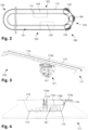
- the Figure 2 is a schematic side view of the circulating track of the machine.
- the Figure 3 shows an oblique view of a gripper conveyor, the Figure 4 a side view of the clamping bar of the gripper conveyor, and the Figures 5A, 5B two oblique views of the base part of the gripper conveyor.
- the Figure 6 is a cross-sectional view illustrating the interaction between the gripper conveyor and the tracl ⁇ , along a plane between the housing and elements for interacting with the tracl ⁇ , attached to or protruding from the housing.
- the circulating transport system 100 includes a circulating track 101 constituted by an upper straight section 102, a lower straight section 103, a first turning section 104 (input side) and a second turning section 105 (output side), the turning sections 104, 105 linl ⁇ ing the upper straight section 102 and the lower straight section 103.
- the upper straight section 102 and the lower straight section 103 are provided by track modules 110
- the turning sections 104, 105 are provided by the end modules 120 (see Fig. 1B, 1C ).
- the main components of the circulating track 101 are the carrying rail 113, the guide rail 114 and the electromagnets 116 (not shown in Fig. 2 ).
- the described track has a length of about 2x10m plus the two turning sections, along the track the linear motor features about 90 electromagnets 116, 30 gripper conveyors 150 and 15 support conveyors 190 are simultaneously interacting with the track 101.
- the gripper conveyors 150 and support conveyors 190 interact with the carrying rail 113 at two points of contact and with the guide rail 114 at a further point of contact, as described in more detail below.
- An air supply station 130 is provided in the lower straight section 103.
- An air supply mechanism 140 is provided in the upper straight section 102, in the region of the printing station 50.
- the gripper conveyor 150 includes a base part 151 and a clamping bar 171 mounted on top of the base part 151.
- the Figures 3, 4 show a clamping bar 171 which is designed to clamp a trailing edge of an individual sheet to be processed.
- the clamping bar 171 features a main profile 172, which is prismatic and has a basically trapezoid cross-section. The longer of the parallel sides of the trapezoid constitutes the upper surface of the clamping bar 171, together with extensions extending to both sides.
- the upper surface is a support surface 173 for the individual sheet to be processed. It features a slit 174 extending from one lateral end of the clamping bar 171 to the other.
- a clamping spring 175 made of spring steel is attached to one of the extensions of the main profile 172.
- a first section 175a of the clamping spring 175 is supported on the inner face of the extension and mounted to the main profile 172 by a mounting blocl ⁇ 176 screwed to the extension.
- a second section 175b of the clamping spring 175 extends from the first section 175a, bent to the inside of the main profile 172 by an angle of about 45°.
- a third section 175c extends from the second section, bent to the upper surface of the clamping bar 171 by an angle of about 45°, i. e. the third section 175c extends parallel to the upper surface (support surface 173).
- L-shaped clamping elements 175d Attached to the free end of the third section 175c are L-shaped clamping elements 175d, arranged along the whole length of the clamping spring 175, and penetrating the slit 174 in the support surface 173, the shorter leg of the clamping elements 175d being supported on the support surface 173, i. e. on the outside of the main profile 172.
- the clamping bar 171 further comprises an elongated inflatable tube 181. It is attached to the section of the main profile 172 forming the shorter parallel side of the trapezoid and is arranged in between this section of the profile 172 and the third section 175c of the clamping spring 175. In the deflated state shown in Fig. 4 , the tube 181 does not impact any force on the clamping spring 175, and due to its geometry and elasticity, the clamping spring 175 exerts a certain clamping force to the support surface 173 of the clamping bar 171.
- the inflatable tube 181 is a closed air container and features a single access, linl ⁇ ed to a vent. In an uninflated state, the tube 181 has an oval cross-section. By inflating the tube 181 with compressed air, the tube 181 changes its shape to a more circular cross-section, i. e. the height of the tube 181 increases and its width decreases. This has the effect that the third section 175c of the clamping spring 175 is contacted by the outer surface of the tube 181 and moved in the direction of the support surface 173. The clamping elements 175d are moved as well and their short legs are raised from the support surface 173, such that a gap is formed for receiving a sheet edge. The maximum gap height exceeds the maximum thicl ⁇ ness of the substrates to be processed. In the shown case, the maximum gap height is 12 mm.
- the base part 151 comprises a housing 152.
- the housing 152 mounts two rail guides 153, 154, both including a rotational bearing, on which a guide element for interacting with a guide rail is mounted. In the Figure 6B, one of the guide elements is displayed, the other is omitted for illustration purposes.
- the two rail guides 153, 154 are arranged near the upper edge of the housing 152, on the front as well as on the back end thereof.
- the rotational axes of the rotational bearings are parallel to each other and run perpendicular to a lateral surface of the housing 152.
- a support roll 155 is mounted in a central section of the lower edge of the housing 152.
- the rotational axis of the support roll 155 runs parallel to the lateral surface of the housing 152 and perpendicular to the support surface 173 of a clamping bar 171 mounted to the base part 151.
- a holding part 158 for mounting a clamping bar 171 (as shown in Figures 3, 4 ).
- the holding part 158 is connected to the housing 152 by a mounting flange as well as by an adjustment lever 159, one of the lateral surfaces of the housing 152 and the holding part 158 forming an essentially L-shaped element, the adjustment lever 159 extending from the housing 152 to the free end of the leg forming the holding part 158.
- the adjustment lever 159 allows for precisely adjusting an angle between the longitudinal extension of the clamping bar 171 and the plane defined by the two rail guides 153, 154 and the support roll 155.
- An air reservoir 161 is accommodated in the housing 152.
- An air interface 162 is connected to the air reservoir 161 by a line including a checl ⁇ valve. This allows for introducing pressurized air through the air interface 162 into the air reservoir 161.
- the air reservoir 161 is further connected to a multiport valve 163. This valve may be switched between two modes of operation by means of a control pin 164 arranged on an lower surface of the housing 152 as follows: control pin line reservoir - tube line tube - exterior effect not operated closed open tube is deflated operated (pressed) open closed tube is inflated
- the base part 151 of the gripper conveyor 150 features a permanent magnet bar 165 for interacting with the electromagnets of the stationary part of the linear motor.
- the magnets are sealed in a slab of synthetic resin.
- the slab is mounted on a lateral surface of the housing 152, on the same side as the guide elements of the rail guides 153, 154.
- a gripper conveyor 150 with the carrying rail 113, the guide rail 114 and the electromagnets 116 of the circulating track 101 is discussed in connection with Figure 6 . It shows a part of the circulating track 101 in one of the end modules, where the track is curved.
- the two rail guides 153, 154 on the base part 151 of the gripper conveyor 150 interact with the carrying rail 113. They are constructed in such a way that lateral as well as normal forces may be transmitted between the gripper conveyor 150 and the carrying rail 113. There are three points of contact, ensuring a defined position of the conveyor with respect to the track at all times, also in the curved sections.
- the permanent magnet bar 165 is arranged on the base part 151 in such a way that it aligns with one or two of the local electromagnets 116.
- the support roll 155 runs on a lateral surface of the guide rail 114 and supports the gripper conveyor 150 against tilting about an axis in the transport direction. By appropriately switching the electromagnets 116, the gripper conveyor 150 moves along the circulating track 101 in a predetermined direction with a predetermined individual speed.
- the supply station 130 features a compressor and a tank for storing compressed air.
- the tank is connected to a supply pin arranged on a carriage that may be moved along a linear path by a belt drive driven by a drive motor.
- a hose linl ⁇ ing the tank to the supply pin is guided by a guide chain such that high speed movements of the carriage are enabled.
- the supply pin is mounted on the carriage by means of a pneumatic cylinder, which allows for extending or retracting the supply pin with respect to the carriage in a direction perpendicular to the linear path.
- the free end of the supply pin is provided by a valve, which is opened if a force acts against a valve tip extending from the supply pin.
- the geometry of the supply pin is adapted to the air interface 162 of the base part 151 of the gripper conveyor 150 (cf. Figure 5A ).
- the carriage Prior to a gripper conveyor entering the air supply section of the circulating track 101, the carriage is moved to its initial position. As soon as the gripper conveyor 150 is aligned with the carriage, the supply pin is extended by means of the pneumatic cylinder. It enters the air interface 162 of the gripper conveyor 150, and the flow of compressed air is activated by the mechanical contact between a collar of the air interface 162 and the valve tip of the air supply pin. Next, the carriage with the air supply inserted into the air interface 162 follows the linear movement of the gripper conveyor 150 until a retraction point is reached. During this movement, pressurized air is introduced through the air interface 162 into the air reservoir 161 on the gripper conveyor 150.
- the amount of air is sufficient to operate the gripper mechanism of the gripper conveyor 150 during a full cycle on the circulating tracl ⁇ .
- the air supply pin is retracted by means of the pneumatic cylinder, and the air supply is automatically stopped as soon as the valve tip loses mechanical contact with the air interface. Finally, the carriage moves back to its initial position, in order to interact with the next guide conveyor.
- the Figure 7 is an oblique view of a support conveyor.
- the support conveyor 190 includes a base part (not shown in Figure 7 ) and a support bar 191.
- the base part essentially corresponds to the base part of the gripper conveyor as shown in Figures 5A, 5B .
- an air reservoir is missing and the air interface is connected to the Bernoulli cups.
- the interaction of the base part of the support conveyor with the circulating track corresponds to the interaction between the gripper conveyor and the tracl ⁇ .
- the support bar 191 features a main profile 192, which is prismatic and has a basically trapezoid cross-section, the longer of the parallel sides of the trapezoid constituting the upper surface of the support bar 191.
- the upper surface 193 features a leading region 193a and a trailing region 193b, separated by a slit 194 extending from one lateral end of the support bar 191 to the other.
- the leading region 193a features eleven Bernoulli cups 195 which are evenly distributed along the bar.
- the Bernoulli cups 195 are connected to the air interface in the base part. Using vents arranged in the supply lines, some of the cups in the outer regions of the support bar 191 may be selectively activated or deactivated.
- the slit 194 provides an escape for the air flow generated by the Bernoulli cups 195 and therefore prohibits the buildup of an extensive air cushion between the support bar 191 and the supported sheet, which would deteriorate the precision of the sheet support.
- the trailing region 193b of the upper surface 193 is provided by a number of circular holes. They help reducing the weight of the support bar 191.
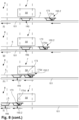
- the Figure 8 is a schematic illustration of the process of gripping and transporting of a sheet.
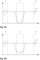
- the Figures 9A , B are diagrams showing the speeds of the gripper and support conveyors as a function of location on the machine's track according to two alternative operating procedures.
- the sheets 5 are fed from the second unit of the feeding station, held by the upper set of belts and a corresponding vacuum system.
- the first gripper conveyor 150.1 prior to feeding the sheet 5, the first gripper conveyor 150.1 is positioned along the circulating track 101 in a receiving position in a receiving region 6, a transport speed v 1 of the gripper conveyor 150.1 (dot-dashed line) is less than a (constant) feeding speed v s of the sheet 5.
- the track 101 features a cam, which interacts with the control pin 164 of the gripper conveyor to inflate the tube 181. This opens the clamping elements 175d of the gripper conveyor 150.1.
- the sheet 5 is inserted with its leading edge in between the clamping elements 175d and the upper surface 173 of the gripper conveyor 150.
- the cam ends the control pin 164 extends and the tube 181 is deflated.
- the belts end i. e. the handover of the respective portion of sheet 5 to the conveyors of the transport system is finished. This leads to the situation depicted in Figure 8 (b) .
- the first gripper conveyor 150.1 is further moved along the track 101 and a support conveyor 190 is moved below the sheet 5.
- the support conveyor 190 has the same general buildup as the gripper conveyors 150, however there is no gripping mechanism and therefore no air reservoir or tube. Initially, the support conveyor 190 supports the sheet 5 in a front region thereof, adjacent to the edge being gripped by the first gripper conveyor 150.1, as shown in Figure 8 (c) . In this phase, the support conveyor 190 follows the first gripper conveyor 150.1 with a speed v 3 corresponding essentially to the feeding speed v s of the sheet and to the speed v 1 of the first gripper conveyor 150.1.
- a contact element coupled to the free end of a movable flexible hose is connected to a quicl ⁇ -action coupling of the support conveyor 190.
- This automatically opens a vent, such that pressurized air is supplied to the support conveyor, where it is distributed to those Bernoulli cups that are activated.
- the hose is coupled until the support conveyor 190 reaches a releasing region 8. There, the quicl ⁇ -action coupling is released, by a control pin interacting with a cam of the track 101 and the hose is retracted. A carrier of the hose is recirculated to the initial position in the receiving region 6.
- the clamping elements 175d are opened due to interaction of the control pin 164 with the cam, see Figure 8 (d) showing a rear region of the track.
- the trailing edge of the sheet 5 is received in between the clamping elements 175d and the upper surface 173 of the second gripper conveyor 150.2.
- the control pin 164 extends and the tube 181 is deflated.
- the sheet 5, held by both gripper conveyors 150.1, 150.2 and supported by the support conveyor 190 in a front region is further transported until the printing station 50 is reached.
- the region of the sheet 5 that is processed by the printing station is supported by the first gripper conveyor 150.1 and the support conveyor 190, see Fig. 8 (c), 8 (e) .
- the speed v 3 of the support conveyor 190 is reduced.
- the Figures 9A, 9B show two different possibilities. According to the progression in Fig. 9A , the support conveyor 190 is standing still in a position facing the printing station 50, i. e. the speed v 3 goes down to zero. According to the progression in Fig.
- the support conveyor 190 is slowed down to a certain small speed but it is never completely standing still.
- the speeds of the two gripper conveyors 150.1, 150.2 may be adjusted to impart some tensioning force on the sheet 5.
- the gripper conveyors do not require any energy supply. This is due to the following:
- the control system of the printing machine is connected to appropriate sensors for determining the positions of all the grippers.
- the handover of the sheets from the gripping conveyors to the removal station essentially corresponds to the feeding of the sheets.
- the speed v 1 of the first gripper conveyor 150.1 is increased such that the leading edge of the sheet is released and the conveyor goes into recirculation.
- the speed v 2 of the second gripper conveyor 150.2 is temporarily decreased to release the trailing edge of the sheet.
- the speed v 2 is increased to recirculate the second gripper conveyor 150.2. This also applies to the support conveyor 190.
- the gripper conveyors and support conveyors are further moved along the tracl ⁇ , passing the first turning section, the lower linear section with the air supply station and the second turning section.
- the speed of the conveyors is substantially higher than on the upper linear section. This allows for reducing the recirculation speed in the air supply station and ensures that the gripper conveyors are timely supplied for the next cycle.
- the printing machine may further comprise a cleaning station for cleaning the gripper and support conveyors. It may be arranged in the vicinity of the air supply station.
- the support conveyor includes a vacuum system in addition to the Bernoulli cups.
- the vacuum system is constituted by vacuum chambers that are arranged immediately below the upper surface of the support bar. The latter is provided by a large number of evenly distributed orifices connecting the respective vacuum chamber with the space above the upper surface.
- the Bernoulli cups are arranged in a central line along the width of the support conveyor. They are surrounded by the orifices of the vacuum system, which essentially extends over the entire upper surface of the support bar.
- the invention provides an inkjet printing machine that allows for flexible processing of different sized sheets as well as for increased dynamics and throughput.
Landscapes
- Engineering & Computer Science (AREA)
- Mechanical Engineering (AREA)
- Feeding Of Articles By Means Other Than Belts Or Rollers (AREA)
- Discharge By Other Means (AREA)
- Delivering By Means Of Belts And Rollers (AREA)
Description
- The invention relates to an inkjet printing machine for printing individual sheets, the machine comprising at least one printing station and a transport system for transporting the individual sheets through the printing station, along a transport direction. The invention further relates to an inkjet printing process for printing individual sheets.
- Inkjet printing machines for the printing of individual sheets, such as sheets of corrugated cardboard, are I<nown.
- As an example,
DE 10 2014 203 821 A1 (Xerox) discloses an image registration system which helps to accurately produce an image onto an oversized media substrate (e. g. of corrugated cardboard) in a large scale printer, for example an inkjet printer. The system includes a rail support tracl<, a printing zone and a platen cart moveable along the rail support track through said printing zone. The image registration system also includes an image capturing apparatus for capturing a position of the media substrate in relation to the platen cart in order to ensure accurate image on media substrate reproduction. -
DE 10 2007 014 876 B4 (KBA Metronic) discloses a conveyor system having an elongated guide defining a closed transport path extending through a plurality of treatment stations, especially treatment stations of a printing machine, and a plurality of carriers movable on the guide along the path and each capable of holding a respective worl<piece. At least one magnet is provided on each carrier, and an annular row of individually energizeable electromagnets extends along the path and is capable of exerting force on the magnets of the carriers so as to displace the respective carriers along the path. -
DE 10 2017 205868 discloses an inkjet printing machine and process according to the preamble ofclaims 1 and 13 respectively. - The machines according to the prior art comprise platen carts or carriers, respectively, wherein each of the carts or carriers is capable of holding a worl<piece. If worl<pieces of different dimensions shall be processed, the carts or carriers need to be replaced, or elements for holding the worl<pieces on the carts or carriers need to be readjusted. This leads to considerable changeover times and may require additional storage space for the different carts or carriers needed. Furthermore, in the case of large individual sheets, suitable carts or carriers are bull<y and have a considerable weight, thus reducing the achievable dynamics and throughput with respect to the sheet transport.
- It is the object of the invention to create a printing machine pertaining to the technical field initially mentioned, that allows for flexible processing of different sized sheets as well as for increased dynamics and throughput.
- The solution of the invention is specified by the features of
claim 1. The transport system comprises at least one gripper conveyor movable along the transport direction, for gripping one of the individual sheets defining a sheet position in transport direction, and the transport system further comprises at least one support conveyor movable along the transport direction for supporting a region of the individual sheet, wherein the supported individual sheet and the support conveyor are movable along the transport direction with respect to each other. - In particular, the support conveyor supports a region of the individual sheet extending over the entire width of the sheet (across the transport direction) but only over part of the length of the individual sheet (in transport direction). The extension of the supported region in the transport direction is substantially smaller than the corresponding extension of the sheet that is not supported by the gripper conveyor (or the gripper conveyors). After all, support of the sheet to be printed on is primarily required in the printing region of the printing station.
- The sheet and the support conveyor are movable at least along the transport direction with respect to each other even in the supported state of the sheet, i. e. the position of the support conveyor with respect to the sheet is not fixed. It is to be noted that relative movement between the sheet and the support conveyor may be in transport direction or against the transport direction.
- Instead of having a rather bull<y and heavy carrier supporting the sheeting over its entire surface, a gripper conveyor (or two or more gripper conveyors) is combined with at least one support conveyor. The gripper conveyor as well as the support conveyor are substantially less bull<y and much lighter. Furthermore, adaptation to different sheet sizes is facilitated.
- The additional support conveyor improves the flatness of the individual sheet. This is particularly advantageous in the case of large substrates or substrates with low inherent stability. Due to the fact that the support conveyor is movable with respect to the sheet, the optimum support position (e. g. with respect to the printing station) may always be chosen and the longitudinal extension of the support conveyor may be minimized, which reduces the weight and inertia of the support conveyors (thus increasing the achievable dynamics of the machine) and facilitates the handling thereof.
- The machine includes a control system for controlling a movement of the gripper conveyor and the support conveyor such that the supported region coincides with a printing region of the printing station.
- Accordingly, an inkjet printing process for printing individual sheets comprises the steps of:
- a) gripping one of the individual sheets by a gripper conveyor running in a transport direction;
- b) the gripper conveyor transporting the gripped sheet along the transport direction, through a printing station;
- c) during transport through the printing station, supporting a region of the gripped sheet by a support conveyor running in the transport direction, wherein a distance between the gripper conveyor and the support conveyor is changed during the transport through the printing station in order to ensure that the supported region coincides with a printing region of the printing station.
- Tal<ing into account the present location of the gripper conveyor(s), the location of the support conveyor is chosen in such a way that the sheet is stably supported in the printing region. If no gripper conveyor is in the printing region or immediately adjacent thereto, the location of the support conveyor will be generally opposite the printing station, in the printing region. Preferably, the longitudinal extension of the support conveyor is chosen such that the sheet is supported with perfect flatness in the printing region.
- Preferably, during transport through the printing station, a transport speed of the support conveyor is smaller than a transport speed of the gripper conveyor. The control system is designed to control the speeds accordingly. This allows for controlling the movements of the gripper conveyor(s) and of the support conveyor in such a way that in a first stage, the support conveyor is supporting a region close to the leading edge of the transported sheet. Subsequently, the support conveyor "lags" with respect to the gripper conveyor(s) and therefore supports regions of the sheet further away from the leading edge, approaching the trailing edge.
- In certain cases, especially for the processing of comparably small sheets, it will not be required to change the distance between the gripper conveyor and the support conveyor during the transport through the printing station. The inventive printing machine allows for a corresponding mode of operation.
- Preferably, the support conveyor comprises a pneumatic system for supporting the individual sheet on an interacting surface of the support conveyor. In the present context, "support" includes contact support (by mechanical contact) as well as non-contact support (e. g. by means of an air cushion). Pneumatic systems may help reducing the immediate contact between the sheet and the support conveyor and thus negative mechanical impacts to the sheet. Furthermore, the effect of pneumatic systems may be easily controlled by adjusting the amount of air supplied, pressure and/or underpressure. This allows for flexibly adapting the characteristics of the support to the stages of the process and/or different characteristics such as sheet size, thicl<ness and material or the printing process, respectively.
- Advantageously, the pneumatic system comprises a cushioning device for providing a support cushion between the interacting surface and the individual sheet supported by the support conveyor. Air cushions reduce friction between the interacting surface and the individual sheets.
- In a preferred embodiment, the cushioning device comprises a plurality of Bernoulli cups for holding the sheet in a predetermined distance of the interacting surface of the support conveyor. Bernoulli cups allow for supporting substrates, especially thin substrates such as sheets, with minimum contact and without substantially hindering relative movement between the sheet and the cups parallel to the sheet plane. They allow for guiding a substrate in a predetermined distance from a surface, which means that they allow for precisely positioning the sheet in a predetermined height and therefore in a predetermined distance from a printing device (i. e. print bars). This ensures invariable high printing quality. For their operation the Bernoulli cups need pressurized air, no vacuum supply is required.
- Instead of or in addition to Bernoulli cups, the cushioning device may include other elements such as hollow pads connected to a compressed air supply.
- In a preferred embodiment, the pneumatic system comprises a vacuum system comprising a plurality of orifices in the interacting surface.
- In a particularly preferred embodiment, an cushioning device, in particular an air cushioning device comprising a plurality of Bernoulli cups, is combined with a vacuum system. This allows for homogenously supporting the sheet, thus improving the sheet flatness, and at the same time moving the support conveyor relative to the sheet with reduced friction. Furthermore, having a vacuum system as well as a cushioning device improves the flexibility of the device with respect to handling substrate of different sizes and/or materials as operation parameters of the vacuum system as well as of the cushioning device may suitably adjusted.
- The vacuum system may be constituted by one or several vacuum chambers that are connected to the plurality of orifices in the interacting surface. The Bernoulli cups may be distributed along the width of the support conveyor. Their orifices lead into the interacting surface as well.
- Preferably, the support conveyor comprises a mechanism for adapting the pneumatic system to a sheet width of the processed individual sheet. In particular, individual elements of the pneumatic system (such as Bernoulli cups and/or vacuum orifices or chambers and/or groups of Bernoulli cups and/or vacuum orifices or chambers) may be selectively switched on and off. This allows for switching off elements lying completely or partially outside the paper width. The switching mechanism may include valves for the closing and opening of supply lines and/or sliders for covering individual or groups of elements.
- Preferably, the machine includes a supply mechanism comprising a movable supply element that may be temporarily coupled to the support conveyor for the supply of compressed air and/or vacuum. Accordingly, during transport through the printing station, the support conveyor is temporarily coupled to the movable supply element of the supply mechanism for the supply of compressed air and/or vacuum. This allows for feeding required amounts of compressed air (or providing vacuum) as long as needed. No local storage is required on the support conveyor.
- The movable supply element may include a flexible hose with a quicl<-action coupling that is coupled with a suitable counterpart element on the support conveyor prior to operation of the pneumatic system, in particular before contacting the sheet. After removal of the sheet, the quicl<-action coupling is decoupled and moved back to the coupling site. More than one hose for coupling to subsequent support conveyors may be used in order to increase throughput. Instead of a flexible hose, a movable carriage carrying a substantially rigid coupling mechanism may be used. This carriage may be passively moved in the transport direction due to the mechanical connection to the support conveyor. The carriage or the hose may be moved back to the starting position by a suitable mechanism, e. g. by a pneumatic mechanism or a pusher driven by a linear drive.
- Instead of Bernoulli cups, air bearings may be used, in particular aerostatic bearings. In principle, vacuum systems are also applicable, however measures need to be tal<en to ensure that relative movement between the sheet and the support conveyor is not prevented.
- Alternatively, the support conveyor mechanically supports the individual sheets. In applications where the individual sheets are fully or partially made from a ferromagnetic material, magnetic support systems may be used.
- Preferably, the transport system comprises a circulating tracl<, wherein the at least one gripper conveyor and the at least one support conveyor are running along the circulating track and wherein a section of the circulating track extends in transport direction. Having a circulating track simplifies the recirculation of the gripper conveyors and support conveyors, no additional recirculation system is needed, and the gripper and support conveyors are always arranged on the tracl<, i. e. during normal operation, no introduction or removal of gripper or support conveyors is required. During operation of the printing machine, the gripper and support conveyors will usually stand still or move in a single predetermined direction.
- Advantageously, the circulating track extends in a first plane, and the gripper and support conveyors are guided along the circulating track in such a way that along the transport track a main surface of individual sheets held by the gripper conveyors and supported by the support conveyors extends in a second plane, the second plane being perpendicular to the first plane and oriented along the transport direction. In particular, the first plane is oriented in a vertical direction, the second plane as well as the transport direction are oriented horizontally. This means that the footprint of the printing machine is not substantially affected by having a circulating tracl<, as the recirculation of the gripper conveyors happens below (preferred) or above the transport tracl<.
- Preferably, the transport system further comprises a linear motor being controllable in such a way that movements of the at least one gripper conveyor and of the at least one support conveyor along the circulating track are individually controllable. This means in principle that the movement of a given gripper conveyor or support conveyor may be controlled independently from the movement of every other gripper conveyor or support conveyor (or further moveable units interacting with the transport tracl<). It is to be noted that during operation of the printing machine movements of several gripper conveyors and support conveyors will usually be synchronized, and there may be constraints with respect to the relative positions and movements of several gripper conveyors and support conveyors that have to be tal<en into account when controlling the movement of the conveyors. Nevertheless, the linear motor and the conveyors are built in such a way that individual control is possible.
- As an alternative to having a linear motor with a circulating tracl<, a linear motor may be used for a straight track leading through the printing station, and other means are provided for recirculating the gripper conveyors to the start of the straight tracl<.
- Advantageously, at least one first gripper conveyor comprises a gripper mechanism for gripping a leading edge of one of the individual sheets and at least one second gripper conveyor comprises a gripper mechanism for gripping a trailing edge of the individual sheet. Accordingly, for transporting the individual sheet through the printing station, a leading edge of the sheet is gripped by the first gripper conveyor and a trailing edge of the sheet is gripped by the second gripper conveyor, the at least one support conveyor being arranged between the first gripper conveyor and the second gripper conveyor in the transport direction.
- Gripping the individual sheets along their leading edge and their trailing edge allows for efficient and flexible handling of individual sheets, in particular large format sheets of materials such as corrugated cardboard or other materials that have a certain degree of inherent stability (such as thick cardboard sheets, plastic sheets, thin metal sheets etc.). Due to the fact that the gripper conveyors are individually controllable, the machine is easily readjusted for different sheet formats. There is no need for having a cart or carrier the dimensions of which matching the dimensions of the sheets to be processed, but the readjustment of the relative distance of the gripper conveyors for gripping the leading edge and the trailing edge, respectively, is sufficient for adapting the machine to different sheet dimensions in the transport direction (length). With respect to the sheet dimension across the transport direction (width), at least in the case of rectangular sheets, it does not matter if the grippers exceed the sheet width.
- Having support conveyors to support the substrate between the leading and trailing gripper conveyors, the dimensions of the gripping conveyors along the transport direction may be chosen to be very short, in any case much shorter than the length of the individual sheets. Accordingly, the movable units of the transport system are much smaller and lighter than the carts or carriers of the prior art, thus allowing for faster dynamics and higher throughput. At the same time, adequate support of the sheets is ensured.
- Preferably, after gripping, a distance between the first gripper conveyor and the second gripper conveyor is controlled in such a way that a tensioning force is applied to the individual sheet for straightening the individual sheet. In combination with the supporting action of the support conveyor, this reduces bending of the sheet along the transport direction. Using the individually controllable conveyors, the tensioning force may be precisely controlled.
- Preferably, the printing station comprises a plurality of inkjet print bars, the print bars covering a printing region extending in a direction across the transport direction. In preferred embodiments, the print bars are essentially fixed in a lateral direction, and they cover the whole width of the print area all the time. In other embodiments, scanning print bar arrangements are employed.
- Nevertheless, in general, the invention may be applied to other kinds of printing systems, especially printing systems for the printing of large sheet-lil<e substrates.
- Other advantageous embodiments and combinations of features come out from the detailed description below and the entirety of the claims.
- The drawings used to explain the embodiments show:
- Fig. 1A
- An oblique view of a printing machine according to the invention;
- Fig. 1B, 1C
- detailed views of
Fig. 1A showing the starting and end sections of the machine, respectively; - Fig. 2
- a schematic side view of the circulating track of the machine;
- Fig. 3
- an oblique view of a gripper conveyor;
- Fig. 4
- a side view of the clamping bar of the gripper conveyor;
- Fig. 5A, 5B
- two oblique views of the base part of the gripper conveyor;
- Fig. 6
- a cross-sectional view illustrating the interaction between the gripper conveyor and the tracl<;
- Fig. 7
- an oblique view of a support conveyor;
- Fig. 8
- a schematic illustration of the process of gripping and transporting of a sheet; and
- Fig. 9A, B
- diagrams showing the speeds of the gripper and support conveyors as a function of location on the machine's tracl<.
- In the figures, the same components are given the same reference symbols.
- The
Figure 1A is an oblique view of a printing machine according to the invention, theFigures 1B, 1C are detailed views ofFig. 1A showing the starting and end sections of the machine, respectively. - The
printing machine 1 according to the shown embodiment is a continuously operated single pass inkjet printing machine for printing individual sheets, e. g. from corrugated cardboard. The maximum format of the individual sheets is 2.1 × 1.3 m (width x length). Typical thicl<nesses of corrugated cardboard that may be processed with the machine range from 0.7 to 7.0 mm. The achievable speed is 100 m/min (about 1 sheet per second), the printing resolution is 1'200 dpi. The printing machine is capable of printing water-based inl<, e. g. for the printing of food pacl<aging. - The
printing machine 1 includes in succession a destacl<ingrobot 10 for destacl<ing individual sheets from aninput stack 2, a feedingstation 20, aprecoating station 30, a first dryingstation 41, aprinting station 50 for four-colour inkjet printing, asecond drying station 42, avarnishing station 60, athird drying station 43, aremoval station 70 and a stacl<ingrobot 80 for stacl<ing the processed individual sheets onto anoutput stack 3. Anaccommodating space 90 is provided between theremoval station 70 and the stacl<ingrobot 80. It may accommodate a further station such as a quality control station. A circulatingtransport system 100 extends from the feedingstation 20 to theremoval station 70. It is described in more detail below. - All drying
stations robot 10 and the stacl<ingrobot 80 are articulated arm robots and built alil<e, featuring gripper means for gripping partial stacl<s of individual sheets. Theprinting station 50 as well as the precoating station and thevarnishing station 60 are based on print bars extending over the entire width of the machine. A suitable print bar technology is described inWO 2017/011923 A1 andWO 2017/011924 A1 (filed by Radex AG, now Mouvent SA). - The
input stack 2 has a typical height of about 2 m. From theinput stack 2, the destacl<ingrobot 10 seizes partial stacl<s having a height of about 20 cm, turns them over and feds them to the feedingstation 20. The feedingstation 20 is constituted of afirst unit 21 and asecond unit 22. Thefirst unit 21 comprises a sheet lift and a number of manipulators. The sheet lift receives a partial stack from the destacl<ingrobot 10. The sheets of the partial stack are lifted by the sheet lift. The uppermost sheet is seized by a lateral bar, using a vacuum system, the present lateral position is determined and the sheet is positioned in an exact predetermined lateral position. The orientation is ensured by suitable guides. This exact lateral position and orientation of the sheet is maintained until the sheet is seized by the circulatingtransport system 100. - The sheet is then fed to the
second unit 22 comprising in a first stage a set of upper transport bands and a set of lower transport bands. All transport bands extend in the longitudinal direction, parallel to the transport direction of the sheets. In the first stage, the sheets are received between the two sets of transport bands. In a second stage of thesecond unit 22, the sheets are attached to the top set of belts only, using a vacuum system. It is from this second stage where the sheets are seized by the circulatingtransport system 100. The belt and vacuum system ensures that the sheets are provided in a flat state, their lateral position and orientation corresponding to that defined by the first unit of the feedingstation 20. - The
removal station 70 basically corresponds to the second stage of thesecond unit 22 of the feedingstation 20, i. e. the processed sheets are received from the circulatingtransport system 100 by means of a set of upper vacuum belts. These belts transport the sheets one by one to the next station. - The
Figure 2 is a schematic side view of the circulating track of the machine. TheFigure 3 shows an oblique view of a gripper conveyor, theFigure 4 a side view of the clamping bar of the gripper conveyor, and theFigures 5A, 5B two oblique views of the base part of the gripper conveyor. TheFigure 6 is a cross-sectional view illustrating the interaction between the gripper conveyor and the tracl<, along a plane between the housing and elements for interacting with the tracl<, attached to or protruding from the housing. - The circulating
transport system 100 includes a circulatingtrack 101 constituted by an upperstraight section 102, a lowerstraight section 103, a first turning section 104 (input side) and a second turning section 105 (output side), the turningsections straight section 102 and the lowerstraight section 103. The upperstraight section 102 and the lowerstraight section 103 are provided bytrack modules 110, the turningsections Fig. 1B, 1C ). As shown inFigure 6 , the main components of the circulatingtrack 101 are the carryingrail 113, theguide rail 114 and the electromagnets 116 (not shown inFig. 2 ). The described track has a length of about 2x10m plus the two turning sections, along the track the linear motor features about 90electromagnets gripper conveyors support conveyors 190 are simultaneously interacting with thetrack 101. Thegripper conveyors 150 and supportconveyors 190 interact with the carryingrail 113 at two points of contact and with theguide rail 114 at a further point of contact, as described in more detail below. - An
air supply station 130 is provided in the lowerstraight section 103. Anair supply mechanism 140 is provided in the upperstraight section 102, in the region of theprinting station 50. These components are described in more detail below. - The
gripper conveyor 150 includes abase part 151 and a clampingbar 171 mounted on top of thebase part 151. TheFigures 3, 4 show a clampingbar 171 which is designed to clamp a trailing edge of an individual sheet to be processed. The clampingbar 171 features amain profile 172, which is prismatic and has a basically trapezoid cross-section. The longer of the parallel sides of the trapezoid constitutes the upper surface of the clampingbar 171, together with extensions extending to both sides. The upper surface is asupport surface 173 for the individual sheet to be processed. It features aslit 174 extending from one lateral end of the clampingbar 171 to the other. - A clamping
spring 175 made of spring steel is attached to one of the extensions of themain profile 172. In cross section, afirst section 175a of theclamping spring 175 is supported on the inner face of the extension and mounted to themain profile 172 by a mounting blocl< 176 screwed to the extension. Asecond section 175b of theclamping spring 175 extends from thefirst section 175a, bent to the inside of themain profile 172 by an angle of about 45°. Athird section 175c extends from the second section, bent to the upper surface of the clampingbar 171 by an angle of about 45°, i. e. thethird section 175c extends parallel to the upper surface (support surface 173). Attached to the free end of thethird section 175c are L-shapedclamping elements 175d, arranged along the whole length of theclamping spring 175, and penetrating theslit 174 in thesupport surface 173, the shorter leg of theclamping elements 175d being supported on thesupport surface 173, i. e. on the outside of themain profile 172. - The clamping
bar 171 further comprises an elongatedinflatable tube 181. It is attached to the section of themain profile 172 forming the shorter parallel side of the trapezoid and is arranged in between this section of theprofile 172 and thethird section 175c of theclamping spring 175. In the deflated state shown inFig. 4 , thetube 181 does not impact any force on theclamping spring 175, and due to its geometry and elasticity, the clampingspring 175 exerts a certain clamping force to thesupport surface 173 of the clampingbar 171. - The
inflatable tube 181 is a closed air container and features a single access, linl<ed to a vent. In an uninflated state, thetube 181 has an oval cross-section. By inflating thetube 181 with compressed air, thetube 181 changes its shape to a more circular cross-section, i. e. the height of thetube 181 increases and its width decreases. This has the effect that thethird section 175c of theclamping spring 175 is contacted by the outer surface of thetube 181 and moved in the direction of thesupport surface 173. Theclamping elements 175d are moved as well and their short legs are raised from thesupport surface 173, such that a gap is formed for receiving a sheet edge. The maximum gap height exceeds the maximum thicl<ness of the substrates to be processed. In the shown case, the maximum gap height is 12 mm. - If the
inflatable tube 181 is deflated again, the force between thetube 181 and theclamping spring 175 decreases to substantially zero, and the clamping force between the clampingspring 175 and the sheet (or the support surface 173) is reestablished due to the elasticity of theclamping spring 175. - The
base part 151 comprises ahousing 152. Thehousing 152 mounts two rail guides 153, 154, both including a rotational bearing, on which a guide element for interacting with a guide rail is mounted. In the Figure 6B, one of the guide elements is displayed, the other is omitted for illustration purposes. The two rail guides 153, 154 are arranged near the upper edge of thehousing 152, on the front as well as on the back end thereof. The rotational axes of the rotational bearings are parallel to each other and run perpendicular to a lateral surface of thehousing 152. In a central section of the lower edge of thehousing 152, asupport roll 155 is mounted. The rotational axis of thesupport roll 155 runs parallel to the lateral surface of thehousing 152 and perpendicular to thesupport surface 173 of a clampingbar 171 mounted to thebase part 151. - Attached to the
housing 152 is a holdingpart 158 for mounting a clamping bar 171 (as shown inFigures 3, 4 ). The holdingpart 158 is connected to thehousing 152 by a mounting flange as well as by anadjustment lever 159, one of the lateral surfaces of thehousing 152 and the holdingpart 158 forming an essentially L-shaped element, theadjustment lever 159 extending from thehousing 152 to the free end of the leg forming the holdingpart 158. Theadjustment lever 159 allows for precisely adjusting an angle between the longitudinal extension of the clampingbar 171 and the plane defined by the two rail guides 153, 154 and thesupport roll 155. - An
air reservoir 161 is accommodated in thehousing 152. Anair interface 162 is connected to theair reservoir 161 by a line including a checl< valve. This allows for introducing pressurized air through theair interface 162 into theair reservoir 161. Theair reservoir 161 is further connected to amultiport valve 163. This valve may be switched between two modes of operation by means of acontrol pin 164 arranged on an lower surface of thehousing 152 as follows:control pin line reservoir - tube line tube - exterior effect not operated closed open tube is deflated operated (pressed) open closed tube is inflated - Finally, the
base part 151 of thegripper conveyor 150 features apermanent magnet bar 165 for interacting with the electromagnets of the stationary part of the linear motor. The magnets are sealed in a slab of synthetic resin. The slab is mounted on a lateral surface of thehousing 152, on the same side as the guide elements of the rail guides 153, 154. - The interaction of a
gripper conveyor 150 with the carryingrail 113, theguide rail 114 and theelectromagnets 116 of the circulatingtrack 101 is discussed in connection withFigure 6 . It shows a part of the circulatingtrack 101 in one of the end modules, where the track is curved. The two rail guides 153, 154 on thebase part 151 of thegripper conveyor 150 interact with the carryingrail 113. They are constructed in such a way that lateral as well as normal forces may be transmitted between thegripper conveyor 150 and the carryingrail 113. There are three points of contact, ensuring a defined position of the conveyor with respect to the track at all times, also in the curved sections. - The
permanent magnet bar 165 is arranged on thebase part 151 in such a way that it aligns with one or two of thelocal electromagnets 116. Thesupport roll 155 runs on a lateral surface of theguide rail 114 and supports thegripper conveyor 150 against tilting about an axis in the transport direction. By appropriately switching theelectromagnets 116, thegripper conveyor 150 moves along the circulatingtrack 101 in a predetermined direction with a predetermined individual speed. - In order to supply compressed air to the
air reservoirs 161 of thegripper conveyors 150, thesupply station 130 features a compressor and a tank for storing compressed air. The tank is connected to a supply pin arranged on a carriage that may be moved along a linear path by a belt drive driven by a drive motor. A hose linl<ing the tank to the supply pin is guided by a guide chain such that high speed movements of the carriage are enabled. - The supply pin is mounted on the carriage by means of a pneumatic cylinder, which allows for extending or retracting the supply pin with respect to the carriage in a direction perpendicular to the linear path. The free end of the supply pin is provided by a valve, which is opened if a force acts against a valve tip extending from the supply pin. The geometry of the supply pin is adapted to the
air interface 162 of thebase part 151 of the gripper conveyor 150 (cf.Figure 5A ). - Prior to a gripper conveyor entering the air supply section of the circulating
track 101, the carriage is moved to its initial position. As soon as thegripper conveyor 150 is aligned with the carriage, the supply pin is extended by means of the pneumatic cylinder. It enters theair interface 162 of thegripper conveyor 150, and the flow of compressed air is activated by the mechanical contact between a collar of theair interface 162 and the valve tip of the air supply pin. Next, the carriage with the air supply inserted into theair interface 162 follows the linear movement of thegripper conveyor 150 until a retraction point is reached. During this movement, pressurized air is introduced through theair interface 162 into theair reservoir 161 on thegripper conveyor 150. The amount of air is sufficient to operate the gripper mechanism of thegripper conveyor 150 during a full cycle on the circulating tracl<. At the retraction point, the air supply pin is retracted by means of the pneumatic cylinder, and the air supply is automatically stopped as soon as the valve tip loses mechanical contact with the air interface. Finally, the carriage moves back to its initial position, in order to interact with the next guide conveyor. - The
Figure 7 is an oblique view of a support conveyor. Thesupport conveyor 190 includes a base part (not shown inFigure 7 ) and asupport bar 191. The base part essentially corresponds to the base part of the gripper conveyor as shown inFigures 5A, 5B . In contrast to the base part of the gripper conveyor, an air reservoir is missing and the air interface is connected to the Bernoulli cups. The interaction of the base part of the support conveyor with the circulating track corresponds to the interaction between the gripper conveyor and the tracl<. - The
support bar 191 features amain profile 192, which is prismatic and has a basically trapezoid cross-section, the longer of the parallel sides of the trapezoid constituting the upper surface of thesupport bar 191. Theupper surface 193 features aleading region 193a and a trailingregion 193b, separated by aslit 194 extending from one lateral end of thesupport bar 191 to the other. The leadingregion 193a features elevenBernoulli cups 195 which are evenly distributed along the bar. The Bernoulli cups 195 are connected to the air interface in the base part. Using vents arranged in the supply lines, some of the cups in the outer regions of thesupport bar 191 may be selectively activated or deactivated. - The
slit 194 provides an escape for the air flow generated by the Bernoulli cups 195 and therefore prohibits the buildup of an extensive air cushion between thesupport bar 191 and the supported sheet, which would deteriorate the precision of the sheet support. The trailingregion 193b of theupper surface 193 is provided by a number of circular holes. They help reducing the weight of thesupport bar 191. - The
Figure 8 is a schematic illustration of the process of gripping and transporting of a sheet. TheFigures 9A , B are diagrams showing the speeds of the gripper and support conveyors as a function of location on the machine's track according to two alternative operating procedures. - As described above, the
sheets 5 are fed from the second unit of the feeding station, held by the upper set of belts and a corresponding vacuum system. As shown inFigure 8 (a) , prior to feeding thesheet 5, the first gripper conveyor 150.1 is positioned along the circulatingtrack 101 in a receiving position in a receivingregion 6, a transport speed v1 of the gripper conveyor 150.1 (dot-dashed line) is less than a (constant) feeding speed vs of thesheet 5. In this section, thetrack 101 features a cam, which interacts with thecontrol pin 164 of the gripper conveyor to inflate thetube 181. This opens theclamping elements 175d of the gripper conveyor 150.1. Held by the upper set of belts, thesheet 5 is inserted with its leading edge in between the clampingelements 175d and theupper surface 173 of thegripper conveyor 150. As soon as this has happened, the cam ends, thecontrol pin 164 extends and thetube 181 is deflated. At this place, the belts end, i. e. the handover of the respective portion ofsheet 5 to the conveyors of the transport system is finished. This leads to the situation depicted inFigure 8 (b) . - The first gripper conveyor 150.1 is further moved along the
track 101 and asupport conveyor 190 is moved below thesheet 5. Thesupport conveyor 190 has the same general buildup as thegripper conveyors 150, however there is no gripping mechanism and therefore no air reservoir or tube. Initially, thesupport conveyor 190 supports thesheet 5 in a front region thereof, adjacent to the edge being gripped by the first gripper conveyor 150.1, as shown inFigure 8 (c) . In this phase, thesupport conveyor 190 follows the first gripper conveyor 150.1 with a speed v3 corresponding essentially to the feeding speed vs of the sheet and to the speed v1 of the first gripper conveyor 150.1. Immediately after placing thesupport conveyor 190 below thesheet 5, a contact element coupled to the free end of a movable flexible hose is connected to a quicl<-action coupling of thesupport conveyor 190. This automatically opens a vent, such that pressurized air is supplied to the support conveyor, where it is distributed to those Bernoulli cups that are activated. The hose is coupled until thesupport conveyor 190 reaches a releasingregion 8. There, the quicl<-action coupling is released, by a control pin interacting with a cam of thetrack 101 and the hose is retracted. A carrier of the hose is recirculated to the initial position in the receivingregion 6. - Next, a second gripper conveyor 150.2 is moved along the
track 101 in the receivingregion 6, with a transport speed v2 bigger than the present transport speed v1=vs of the first gripper conveyor 150.1 with thesheet 5. Again, theclamping elements 175d are opened due to interaction of thecontrol pin 164 with the cam, seeFigure 8 (d) showing a rear region of the track. The trailing edge of thesheet 5 is received in between the clampingelements 175d and theupper surface 173 of the second gripper conveyor 150.2. Finally, as soon as the cam ends, thecontrol pin 164 extends and thetube 181 is deflated. - The
sheet 5, held by both gripper conveyors 150.1, 150.2 and supported by thesupport conveyor 190 in a front region is further transported until theprinting station 50 is reached. The region of thesheet 5 that is processed by the printing station is supported by the first gripper conveyor 150.1 and thesupport conveyor 190, seeFig. 8 (c), 8 (e) . In a region immediately upstream theprinting region 7 as well as within theprinting region 7 itself, the speed v3 of thesupport conveyor 190 is reduced. TheFigures 9A, 9B show two different possibilities. According to the progression inFig. 9A , thesupport conveyor 190 is standing still in a position facing theprinting station 50, i. e. the speed v3 goes down to zero. According to the progression inFig. 9B , thesupport conveyor 190 is slowed down to a certain small speed but it is never completely standing still. In both cases, in and around theprinting region 7 the speed v3 is considerably smaller than the speed v1=v2=vs of the two gripper conveyors 150.1, 150.2 and thesheet 5, such that thesupport conveyor 190 lags with respect to the first gripper conveyor 150.1 and thesheet 5 and is approached by the second gripper conveyor 150.2, seeFigure 8 (f) . During transport, in order to further improve the flatness of thesheet 5, the speeds of the two gripper conveyors 150.1, 150.2 may be adjusted to impart some tensioning force on thesheet 5. - As soon as the second gripper conveyor 150.2 approaches the
printing region 7 the speed v3 of thesupport conveyor 190 is again increased until it reaches the transport speed v1=v2=vs of the gripper conveyors 150.1, 150.2 and thesheet 5. Thus thesheet 5 is transported out of theprinting station 50, a rear region immediately adjacent the gripped trailing edge being supported by thesupport conveyor 190, seeFigures 8 (g), 8 (h), 8 (i) . - From receiving the sheets, during the entire processing the sheets and up to hand over the sheets to the removal station, the gripper conveyors do not require any energy supply. This is due to the following:
- the actuation of the gripping mechanism is based on a mechanical interaction between the control pin and the cam,
- the energy required for actuating the gripping mechanism is provided by the air reservoir on the gripping conveyor, and
- the energy for movement of the conveyors is delivered to the stationary electromagnets of the linear motor.
- The only place where external energy is provided to the conveyors is the air supply station, as described above. Nevertheless, despite the passive nature of the conveyors, their movement along the track may be individually controlled. For this purpose, the control system of the printing machine is connected to appropriate sensors for determining the positions of all the grippers.
- The handover of the sheets from the gripping conveyors to the removal station essentially corresponds to the feeding of the sheets. This means that after opening the clamping mechanism in a releasing
region 8, the speed v1 of the first gripper conveyor 150.1 is increased such that the leading edge of the sheet is released and the conveyor goes into recirculation. In contrast, after opening the respective clamping mechanism, the speed v2 of the second gripper conveyor 150.2 is temporarily decreased to release the trailing edge of the sheet. As soon as the sheet has been removed, the speed v2 is increased to recirculate the second gripper conveyor 150.2. This also applies to thesupport conveyor 190. - After handover, the gripper conveyors and support conveyors are further moved along the tracl<, passing the first turning section, the lower linear section with the air supply station and the second turning section. Along a first part of the lower linear section, the speed of the conveyors is substantially higher than on the upper linear section. This allows for reducing the recirculation speed in the air supply station and ensures that the gripper conveyors are timely supplied for the next cycle.
- The printing machine may further comprise a cleaning station for cleaning the gripper and support conveyors. It may be arranged in the vicinity of the air supply station.
- The invention is not restricted to the described embodiment. In particular, dimensions of the machine, the number and type of stations or the geometrical design of machine elements may be different from the shown examples.
- As mentioned above, in another embodiment, the support conveyor includes a vacuum system in addition to the Bernoulli cups. The vacuum system is constituted by vacuum chambers that are arranged immediately below the upper surface of the support bar. The latter is provided by a large number of evenly distributed orifices connecting the respective vacuum chamber with the space above the upper surface. In this embodiment of the support conveyor, the Bernoulli cups are arranged in a central line along the width of the support conveyor. They are surrounded by the orifices of the vacuum system, which essentially extends over the entire upper surface of the support bar.
- In summary, it is to be noted that the invention provides an inkjet printing machine that allows for flexible processing of different sized sheets as well as for increased dynamics and throughput.
Claims (17)
- An inkjet printing machine (1) for printing individual sheets, comprisinga) at least one printing station (50);b) a transport system (100) for transporting the individual sheets through the printing station,along a transport direction; the transport system comprising at least one gripper conveyor (150) movable along the transport direction, for gripping one of the individual sheets defining a sheet position in transport direction,the transport system further comprising at least one support conveyor (190) movable along the transport direction for supporting a region of the individual sheet, wherein the supported individual sheet and the support conveyor are movable along the transport direction with respect to each other; characterised bya control system adapted to control a movement of the gripper conveyor and the support conveyor such that a distance between the gripper conveyor and the support conveyor is changed during the transport through the printing station (50) in order to ensure that the supported region coincides with a printing region (7) of the printing station.
- The inkjet printing machine (1) as recited in claim 1, characterized in that the control system is designed to control a speed of movement(v3) along the transport direction of the support conveyor (190) being smaller than a speed of movement (v) along the transport direction of the gripper conveyor (150), during a printing operation.
- The inkjet printing machine (1) as recited in any of claims 1 to 2, characterized in that the support conveyor (190) comprises a pneumatic system for supporting the individual sheet on an interacting surface (193) of the support conveyor.
- The inkjet printing machine (1) as recited in claim 3, characterized in that the pneumatic system comprises a cushioning device for providing a support cushion between the interacting surface (193) and the individual sheet supported by the support conveyor (190).
- The inkjet printing machine (1) as recited in claim 4, characterized in that the cushioning device comprises a plurality of Bernoulli cups (195) for holding the sheet in a predetermined distance of the interacting surface (193).
- The inkjet printing machine (1) as recited in any of claims 3 to 5, characterized in that the pneumatic system comprises a vacuum system comprising a plurality of orifices in the interacting surface. surface (193).
- The inkjet printing machine (1) as recited in any of claims claims 3 to 6, characterized in that the support conveyor (190) comprises a mechanism for adapting the pneumatic system to a sheet width of the processed individual sheet.
- The inkjet printing machine (1) as recited in any of claims 3 to 7, comprising a supply mechanism (140) comprising a movable supply element that may be temporarily coupled to the support conveyor (190) for the supply of compressed air and/or vacuum.
- The inkjet printing machine (1) as recited in one of claims 1 to 8, the transport system (100) comprising a circulating track (101), wherein the at least one gripper conveyor (150) and the at least one support conveyor (190) are running along the circulating track and wherein a section (102) of the circulating track extends in transport direction.
- The inkjet printing machine (1) as recited in claim 9, the transport system (100) further comprising a linear motor being controllable in such a way that movement of the at least one gripper conveyor (150) and of the at least one support conveyor (190) along the circulating track are individually controllable.
- The inkjet printing machine (1) as recited in any of claims 1 to 10, comprising at least one first gripper conveyor (150.1) comprising a gripper mechanism for gripping a leading edge of one of the individual sheets and at least one second gripper conveyor (150.2) comprising a gripper mechanism for gripping a trailing edge of the individual sheet.
- The inkjet printing machine (1) as recited in any of claims 1 to 11, the printing station (50) comprising
a plurality of inkjet print bars, the print bars covering a printing region (7) extending in a direction across the transport direction. - An inkjet printing process for printing individual sheets, comprising the steps of:a) gripping one of the individual sheets by a gripper conveyor (150) running in a transport direction;b) the gripper conveyor transporting the gripped sheet along the transport direction, through a printing station (50); characterised byc) during transport through the printing station, supporting a region of the gripped sheet by a support conveyor (190) running in the transport direction, wherein a distance between the gripper conveyor and the support conveyor is changed during the transport through the printing station in order to ensure that the supported region coincides with a printing region (7) of the printing station.
- The inkjet printing process as recited in claim 13, +4r characterized in that during transport through the printing station (50), a transport speed (v3) of the support conveyor (190) is smaller than a transport speed (v) of the gripper conveyor (150).
- The inkjet printing process as recited in claim 13 or 14, characterized in that during transport through the printing station (50), the support conveyor (190) is temporarily coupled to a movable supply element of a supply mechanism (140) for the supply of compressed air and/or vacuum.
- The inkjet printing process as recited in any of claims 13 to 15, characterized in that a leading edge of the sheet is gripped by a first gripper conveyor (150.1) and a trailing edge of the sheet is gripped by a second gripper conveyor (150.2), the support conveyor (190) being arranged between the first gripper conveyor and the second gripper conveyor in the transport direction.
- The inkjet printing process as recited in claim 16, characterized in that after gripping, a distance between the first gripper conveyor (150) and the second gripper conveyor (190) is controlled in such a way that a tensioning force is applied to the individual sheet for straightening the individual sheet.
Applications Claiming Priority (1)
| Application Number | Priority Date | Filing Date | Title |
|---|---|---|---|
| PCT/EP2019/057151 WO2020187426A1 (en) | 2019-03-21 | 2019-03-21 | Inkjet printing machine for printing individual sheets |
Publications (2)
| Publication Number | Publication Date |
|---|---|
| EP3941864A1 EP3941864A1 (en) | 2022-01-26 |
| EP3941864B1 true EP3941864B1 (en) | 2024-04-24 |
Family
ID=65911167
Family Applications (2)
| Application Number | Title | Priority Date | Filing Date |
|---|---|---|---|
| EP19713430.7A Active EP3941864B1 (en) | 2019-03-21 | 2019-03-21 | Inkjet printing machine for printing individual sheets |
| EP20711185.7A Active EP3941865B1 (en) | 2019-03-21 | 2020-03-18 | Machine for processing individual sheets |
Family Applications After (1)
| Application Number | Title | Priority Date | Filing Date |
|---|---|---|---|
| EP20711185.7A Active EP3941865B1 (en) | 2019-03-21 | 2020-03-18 | Machine for processing individual sheets |
Country Status (5)
| Country | Link |
|---|---|
| US (2) | US11801695B2 (en) |
| EP (2) | EP3941864B1 (en) |
| CN (2) | CN113874305B (en) |
| ES (2) | ES2980257T3 (en) |
| WO (2) | WO2020187426A1 (en) |
Families Citing this family (2)
| Publication number | Priority date | Publication date | Assignee | Title |
|---|---|---|---|---|
| WO2020035134A1 (en) * | 2018-08-14 | 2020-02-20 | Mouvent Ag | Inkjet printing machine for printing individual sheets |
| WO2026002917A1 (en) | 2024-06-25 | 2026-01-02 | Bobst Mex Sa | Inkjet printing system |
Family Cites Families (20)
| Publication number | Priority date | Publication date | Assignee | Title |
|---|---|---|---|---|
| DE8704590U1 (en) | 1987-03-27 | 1987-05-27 | Carl Schmale GmbH & Co KG, 4434 Ochtrup | Transport pliers |
| JP4249869B2 (en) * | 1999-12-22 | 2009-04-08 | 株式会社オーク製作所 | Substrate transfer device |
| EP1721750A1 (en) * | 2005-05-09 | 2006-11-15 | Agfa-Gevaert | Media holding assistance for a step-wise media transport system in a digital printer |
| DE102007014876B4 (en) | 2007-03-26 | 2010-04-08 | Kba-Metronic Aktiengesellschaft | transport system |
| DE102008010985A1 (en) * | 2008-02-25 | 2009-08-27 | Heidelberger Druckmaschinen Ag | Sheet braking mechanism |
| DE202008003610U1 (en) | 2008-03-16 | 2008-05-21 | Jonas & Redmann Automationstechnik Gmbh | Conveyor belt system with at least one conveyor belt for transporting flat cargo, in particular of substrates such as silicon wafers and solar cells |
| US9757963B2 (en) * | 2010-11-01 | 2017-09-12 | Scodix Ltd. | System and method for transporting substrates |
| US8919950B2 (en) | 2011-02-10 | 2014-12-30 | Hewlett-Packard Industrial Printing Ltd. | Pallet transfer device |
| WO2012108870A1 (en) * | 2011-02-10 | 2012-08-16 | Hewlett-Packard Development Company, L.P. | Media transport assembly |
| US8967792B2 (en) * | 2012-12-07 | 2015-03-03 | Xerox Corporation | Moveable platen cart for handling sheets of substrate media in a printing system |
| US8976409B2 (en) * | 2013-03-14 | 2015-03-10 | Xerox Corporation | Large sheet image on paper registration |
| EP3018081B1 (en) | 2014-11-06 | 2017-08-02 | Hewlett-Packard Industrial Printing Ltd. | Pallet conveyors for printers |
| EP3020559B1 (en) * | 2014-11-13 | 2018-02-28 | OCE-Technologies B.V. | Transport mechanism and method for transporting a print medium in a printing system |
| ES2864750T3 (en) | 2015-07-23 | 2021-10-14 | Bobst Mex Sa | Mounting kit for mounting a plurality of inkjet printing modules |
| WO2017011923A1 (en) | 2015-07-23 | 2017-01-26 | Radex Ag | Drop-on-demand inkjet print bar |
| US10655658B2 (en) * | 2016-01-20 | 2020-05-19 | Persimmon Technologies, Corp. | Material handling system |
| DE102017205868A1 (en) * | 2016-05-09 | 2017-11-09 | Heidelberger Druckmaschinen Ag | Transport system for arched elements |
| EP3315309B1 (en) | 2016-10-31 | 2021-08-04 | HP Scitex Ltd | Vacuum within a pallet conveyor for a printing system |
| EP3837199B1 (en) * | 2018-08-14 | 2022-04-06 | Bobst Mex Sa | Inkjet printing machine for printing individual sheets |
| WO2020035134A1 (en) * | 2018-08-14 | 2020-02-20 | Mouvent Ag | Inkjet printing machine for printing individual sheets |
-
2019
- 2019-03-21 EP EP19713430.7A patent/EP3941864B1/en active Active
- 2019-03-21 CN CN201980096656.9A patent/CN113874305B/en active Active
- 2019-03-21 US US17/593,487 patent/US11801695B2/en active Active
- 2019-03-21 WO PCT/EP2019/057151 patent/WO2020187426A1/en not_active Ceased
- 2019-03-21 ES ES19713430T patent/ES2980257T3/en active Active
-
2020
- 2020-03-18 US US17/593,494 patent/US11890868B2/en active Active
- 2020-03-18 WO PCT/EP2020/057524 patent/WO2020188008A1/en not_active Ceased
- 2020-03-18 CN CN202080037769.4A patent/CN113966305B/en active Active
- 2020-03-18 ES ES20711185T patent/ES3059238T3/en active Active
- 2020-03-18 EP EP20711185.7A patent/EP3941865B1/en active Active
Also Published As
| Publication number | Publication date |
|---|---|
| WO2020187426A1 (en) | 2020-09-24 |
| CN113874305A (en) | 2021-12-31 |
| ES2980257T3 (en) | 2024-09-30 |
| WO2020188008A1 (en) | 2020-09-24 |
| EP3941865B1 (en) | 2025-12-10 |
| CN113966305A (en) | 2022-01-21 |
| US11801695B2 (en) | 2023-10-31 |
| US11890868B2 (en) | 2024-02-06 |
| US20220219926A1 (en) | 2022-07-14 |
| EP3941864A1 (en) | 2022-01-26 |
| EP3941865A1 (en) | 2022-01-26 |
| ES3059238T3 (en) | 2026-03-19 |
| CN113966305B (en) | 2024-04-12 |
| CN113874305B (en) | 2023-08-15 |
| US20220219467A1 (en) | 2022-07-14 |
Similar Documents
| Publication | Publication Date | Title |
|---|---|---|
| KR101453702B1 (en) | Device for printing by stamping | |
| EP3941865B1 (en) | Machine for processing individual sheets | |
| US7118103B2 (en) | Device for conveying sheets through a printing machine | |
| CN110723571A (en) | Printing machine with sheet transport belt | |
| EP3837199B1 (en) | Inkjet printing machine for printing individual sheets | |
| US20090230618A1 (en) | Sheet braking mechanism | |
| EP3837118B1 (en) | Inkjet printing machine for printing individual sheets | |
| CN110228288B (en) | Blowing device unit and gold stamping die cutting equipment | |
| CN113135033A (en) | Apparatus for singulating printing plates | |
| US6776411B2 (en) | Delivery for a machine for processing flat printing materials with adjustable pile underlay inserter conveyor | |
| JP5361423B2 (en) | Image recording device | |
| CN121311427B (en) | A paper receiving device for a machine that processes single sheets of paper, having a stacking carrier that can be vertically moved by a stacking lifting drive. | |
| US8196511B2 (en) | Method for overprinting already printed packages | |
| JPH11199071A (en) | Sheet conveying device | |
| JPH0531544A (en) | Blank feeding device for press |
Legal Events
| Date | Code | Title | Description |
|---|---|---|---|
| STAA | Information on the status of an ep patent application or granted ep patent |
Free format text: STATUS: UNKNOWN |
|
| STAA | Information on the status of an ep patent application or granted ep patent |
Free format text: STATUS: THE INTERNATIONAL PUBLICATION HAS BEEN MADE |
|
| PUAI | Public reference made under article 153(3) epc to a published international application that has entered the european phase |
Free format text: ORIGINAL CODE: 0009012 |
|
| STAA | Information on the status of an ep patent application or granted ep patent |
Free format text: STATUS: REQUEST FOR EXAMINATION WAS MADE |
|
| 17P | Request for examination filed |
Effective date: 20211011 |
|
| AK | Designated contracting states |
Kind code of ref document: A1 Designated state(s): AL AT BE BG CH CY CZ DE DK EE ES FI FR GB GR HR HU IE IS IT LI LT LU LV MC MK MT NL NO PL PT RO RS SE SI SK SM TR |
|
| DAV | Request for validation of the european patent (deleted) | ||
| DAX | Request for extension of the european patent (deleted) | ||
| RIC1 | Information provided on ipc code assigned before grant |
Ipc: B65H 5/22 20060101ALI20231220BHEP Ipc: B41J 11/06 20060101ALI20231220BHEP Ipc: B41J 11/00 20060101ALI20231220BHEP Ipc: B41J 13/00 20060101ALI20231220BHEP Ipc: B65H 5/14 20060101ALI20231220BHEP Ipc: B65H 5/08 20060101ALI20231220BHEP Ipc: B65H 5/04 20060101AFI20231220BHEP |
|
| GRAP | Despatch of communication of intention to grant a patent |
Free format text: ORIGINAL CODE: EPIDOSNIGR1 |
|
| STAA | Information on the status of an ep patent application or granted ep patent |
Free format text: STATUS: GRANT OF PATENT IS INTENDED |
|
| INTG | Intention to grant announced |
Effective date: 20240201 |
|
| GRAS | Grant fee paid |
Free format text: ORIGINAL CODE: EPIDOSNIGR3 |
|
| GRAA | (expected) grant |
Free format text: ORIGINAL CODE: 0009210 |
|
| STAA | Information on the status of an ep patent application or granted ep patent |
Free format text: STATUS: THE PATENT HAS BEEN GRANTED |
|
| AK | Designated contracting states |
Kind code of ref document: B1 Designated state(s): AL AT BE BG CH CY CZ DE DK EE ES FI FR GB GR HR HU IE IS IT LI LT LU LV MC MK MT NL NO PL PT RO RS SE SI SK SM TR |
|
| REG | Reference to a national code |
Ref country code: GB Ref legal event code: FG4D |
|
| REG | Reference to a national code |
Ref country code: CH Ref legal event code: EP |
|
| REG | Reference to a national code |
Ref country code: DE Ref legal event code: R096 Ref document number: 602019050846 Country of ref document: DE |
|
| REG | Reference to a national code |
Ref country code: IE Ref legal event code: FG4D |
|
| REG | Reference to a national code |
Ref country code: LT Ref legal event code: MG9D |
|
| REG | Reference to a national code |
Ref country code: NL Ref legal event code: MP Effective date: 20240424 |
|
| REG | Reference to a national code |
Ref country code: AT Ref legal event code: MK05 Ref document number: 1679408 Country of ref document: AT Kind code of ref document: T Effective date: 20240424 |
|
| PG25 | Lapsed in a contracting state [announced via postgrant information from national office to epo] |
Ref country code: NL Free format text: LAPSE BECAUSE OF FAILURE TO SUBMIT A TRANSLATION OF THE DESCRIPTION OR TO PAY THE FEE WITHIN THE PRESCRIBED TIME-LIMIT Effective date: 20240424 |
|
| PG25 | Lapsed in a contracting state [announced via postgrant information from national office to epo] |
Ref country code: NL Free format text: LAPSE BECAUSE OF FAILURE TO SUBMIT A TRANSLATION OF THE DESCRIPTION OR TO PAY THE FEE WITHIN THE PRESCRIBED TIME-LIMIT Effective date: 20240424 |
|
| REG | Reference to a national code |
Ref country code: ES Ref legal event code: FG2A Ref document number: 2980257 Country of ref document: ES Kind code of ref document: T3 Effective date: 20240930 |
|
| PG25 | Lapsed in a contracting state [announced via postgrant information from national office to epo] |
Ref country code: IS Free format text: LAPSE BECAUSE OF FAILURE TO SUBMIT A TRANSLATION OF THE DESCRIPTION OR TO PAY THE FEE WITHIN THE PRESCRIBED TIME-LIMIT Effective date: 20240824 |
|
| PG25 | Lapsed in a contracting state [announced via postgrant information from national office to epo] |
Ref country code: BG Free format text: LAPSE BECAUSE OF FAILURE TO SUBMIT A TRANSLATION OF THE DESCRIPTION OR TO PAY THE FEE WITHIN THE PRESCRIBED TIME-LIMIT Effective date: 20240424 |
|
| PG25 | Lapsed in a contracting state [announced via postgrant information from national office to epo] |
Ref country code: HR Free format text: LAPSE BECAUSE OF FAILURE TO SUBMIT A TRANSLATION OF THE DESCRIPTION OR TO PAY THE FEE WITHIN THE PRESCRIBED TIME-LIMIT Effective date: 20240424 Ref country code: FI Free format text: LAPSE BECAUSE OF FAILURE TO SUBMIT A TRANSLATION OF THE DESCRIPTION OR TO PAY THE FEE WITHIN THE PRESCRIBED TIME-LIMIT Effective date: 20240424 |
|
| PG25 | Lapsed in a contracting state [announced via postgrant information from national office to epo] |
Ref country code: GR Free format text: LAPSE BECAUSE OF FAILURE TO SUBMIT A TRANSLATION OF THE DESCRIPTION OR TO PAY THE FEE WITHIN THE PRESCRIBED TIME-LIMIT Effective date: 20240725 |
|
| PG25 | Lapsed in a contracting state [announced via postgrant information from national office to epo] |
Ref country code: PT Free format text: LAPSE BECAUSE OF FAILURE TO SUBMIT A TRANSLATION OF THE DESCRIPTION OR TO PAY THE FEE WITHIN THE PRESCRIBED TIME-LIMIT Effective date: 20240826 |
|
| PG25 | Lapsed in a contracting state [announced via postgrant information from national office to epo] |
Ref country code: AT Free format text: LAPSE BECAUSE OF FAILURE TO SUBMIT A TRANSLATION OF THE DESCRIPTION OR TO PAY THE FEE WITHIN THE PRESCRIBED TIME-LIMIT Effective date: 20240424 |
|
| PG25 | Lapsed in a contracting state [announced via postgrant information from national office to epo] |
Ref country code: PL Free format text: LAPSE BECAUSE OF FAILURE TO SUBMIT A TRANSLATION OF THE DESCRIPTION OR TO PAY THE FEE WITHIN THE PRESCRIBED TIME-LIMIT Effective date: 20240424 |
|
| PG25 | Lapsed in a contracting state [announced via postgrant information from national office to epo] |
Ref country code: LV Free format text: LAPSE BECAUSE OF FAILURE TO SUBMIT A TRANSLATION OF THE DESCRIPTION OR TO PAY THE FEE WITHIN THE PRESCRIBED TIME-LIMIT Effective date: 20240424 |
|
| PG25 | Lapsed in a contracting state [announced via postgrant information from national office to epo] |
Ref country code: PT Free format text: LAPSE BECAUSE OF FAILURE TO SUBMIT A TRANSLATION OF THE DESCRIPTION OR TO PAY THE FEE WITHIN THE PRESCRIBED TIME-LIMIT Effective date: 20240826 Ref country code: PL Free format text: LAPSE BECAUSE OF FAILURE TO SUBMIT A TRANSLATION OF THE DESCRIPTION OR TO PAY THE FEE WITHIN THE PRESCRIBED TIME-LIMIT Effective date: 20240424 Ref country code: NO Free format text: LAPSE BECAUSE OF FAILURE TO SUBMIT A TRANSLATION OF THE DESCRIPTION OR TO PAY THE FEE WITHIN THE PRESCRIBED TIME-LIMIT Effective date: 20240724 Ref country code: LV Free format text: LAPSE BECAUSE OF FAILURE TO SUBMIT A TRANSLATION OF THE DESCRIPTION OR TO PAY THE FEE WITHIN THE PRESCRIBED TIME-LIMIT Effective date: 20240424 Ref country code: IS Free format text: LAPSE BECAUSE OF FAILURE TO SUBMIT A TRANSLATION OF THE DESCRIPTION OR TO PAY THE FEE WITHIN THE PRESCRIBED TIME-LIMIT Effective date: 20240824 Ref country code: HR Free format text: LAPSE BECAUSE OF FAILURE TO SUBMIT A TRANSLATION OF THE DESCRIPTION OR TO PAY THE FEE WITHIN THE PRESCRIBED TIME-LIMIT Effective date: 20240424 Ref country code: GR Free format text: LAPSE BECAUSE OF FAILURE TO SUBMIT A TRANSLATION OF THE DESCRIPTION OR TO PAY THE FEE WITHIN THE PRESCRIBED TIME-LIMIT Effective date: 20240725 Ref country code: FI Free format text: LAPSE BECAUSE OF FAILURE TO SUBMIT A TRANSLATION OF THE DESCRIPTION OR TO PAY THE FEE WITHIN THE PRESCRIBED TIME-LIMIT Effective date: 20240424 Ref country code: BG Free format text: LAPSE BECAUSE OF FAILURE TO SUBMIT A TRANSLATION OF THE DESCRIPTION OR TO PAY THE FEE WITHIN THE PRESCRIBED TIME-LIMIT Effective date: 20240424 Ref country code: AT Free format text: LAPSE BECAUSE OF FAILURE TO SUBMIT A TRANSLATION OF THE DESCRIPTION OR TO PAY THE FEE WITHIN THE PRESCRIBED TIME-LIMIT Effective date: 20240424 Ref country code: RS Free format text: LAPSE BECAUSE OF FAILURE TO SUBMIT A TRANSLATION OF THE DESCRIPTION OR TO PAY THE FEE WITHIN THE PRESCRIBED TIME-LIMIT Effective date: 20240724 |
|
| PG25 | Lapsed in a contracting state [announced via postgrant information from national office to epo] |
Ref country code: DK Free format text: LAPSE BECAUSE OF FAILURE TO SUBMIT A TRANSLATION OF THE DESCRIPTION OR TO PAY THE FEE WITHIN THE PRESCRIBED TIME-LIMIT Effective date: 20240424 |
|
| PG25 | Lapsed in a contracting state [announced via postgrant information from national office to epo] |
Ref country code: EE Free format text: LAPSE BECAUSE OF FAILURE TO SUBMIT A TRANSLATION OF THE DESCRIPTION OR TO PAY THE FEE WITHIN THE PRESCRIBED TIME-LIMIT Effective date: 20240424 |
|
| PG25 | Lapsed in a contracting state [announced via postgrant information from national office to epo] |
Ref country code: CZ Free format text: LAPSE BECAUSE OF FAILURE TO SUBMIT A TRANSLATION OF THE DESCRIPTION OR TO PAY THE FEE WITHIN THE PRESCRIBED TIME-LIMIT Effective date: 20240424 |
|
| PG25 | Lapsed in a contracting state [announced via postgrant information from national office to epo] |
Ref country code: SK Free format text: LAPSE BECAUSE OF FAILURE TO SUBMIT A TRANSLATION OF THE DESCRIPTION OR TO PAY THE FEE WITHIN THE PRESCRIBED TIME-LIMIT Effective date: 20240424 Ref country code: RO Free format text: LAPSE BECAUSE OF FAILURE TO SUBMIT A TRANSLATION OF THE DESCRIPTION OR TO PAY THE FEE WITHIN THE PRESCRIBED TIME-LIMIT Effective date: 20240424 |
|
| REG | Reference to a national code |
Ref country code: DE Ref legal event code: R097 Ref document number: 602019050846 Country of ref document: DE |
|
| PG25 | Lapsed in a contracting state [announced via postgrant information from national office to epo] |
Ref country code: SM Free format text: LAPSE BECAUSE OF FAILURE TO SUBMIT A TRANSLATION OF THE DESCRIPTION OR TO PAY THE FEE WITHIN THE PRESCRIBED TIME-LIMIT Effective date: 20240424 |
|
| PG25 | Lapsed in a contracting state [announced via postgrant information from national office to epo] |
Ref country code: SM Free format text: LAPSE BECAUSE OF FAILURE TO SUBMIT A TRANSLATION OF THE DESCRIPTION OR TO PAY THE FEE WITHIN THE PRESCRIBED TIME-LIMIT Effective date: 20240424 Ref country code: SK Free format text: LAPSE BECAUSE OF FAILURE TO SUBMIT A TRANSLATION OF THE DESCRIPTION OR TO PAY THE FEE WITHIN THE PRESCRIBED TIME-LIMIT Effective date: 20240424 Ref country code: RO Free format text: LAPSE BECAUSE OF FAILURE TO SUBMIT A TRANSLATION OF THE DESCRIPTION OR TO PAY THE FEE WITHIN THE PRESCRIBED TIME-LIMIT Effective date: 20240424 Ref country code: EE Free format text: LAPSE BECAUSE OF FAILURE TO SUBMIT A TRANSLATION OF THE DESCRIPTION OR TO PAY THE FEE WITHIN THE PRESCRIBED TIME-LIMIT Effective date: 20240424 Ref country code: DK Free format text: LAPSE BECAUSE OF FAILURE TO SUBMIT A TRANSLATION OF THE DESCRIPTION OR TO PAY THE FEE WITHIN THE PRESCRIBED TIME-LIMIT Effective date: 20240424 Ref country code: CZ Free format text: LAPSE BECAUSE OF FAILURE TO SUBMIT A TRANSLATION OF THE DESCRIPTION OR TO PAY THE FEE WITHIN THE PRESCRIBED TIME-LIMIT Effective date: 20240424 |
|
| PLBE | No opposition filed within time limit |
Free format text: ORIGINAL CODE: 0009261 |
|
| STAA | Information on the status of an ep patent application or granted ep patent |
Free format text: STATUS: NO OPPOSITION FILED WITHIN TIME LIMIT |
|
| 26N | No opposition filed |
Effective date: 20250127 |
|
| PG25 | Lapsed in a contracting state [announced via postgrant information from national office to epo] |
Ref country code: SI Free format text: LAPSE BECAUSE OF FAILURE TO SUBMIT A TRANSLATION OF THE DESCRIPTION OR TO PAY THE FEE WITHIN THE PRESCRIBED TIME-LIMIT Effective date: 20240424 |
|
| PGFP | Annual fee paid to national office [announced via postgrant information from national office to epo] |
Ref country code: ES Payment date: 20250414 Year of fee payment: 7 |
|
| PGFP | Annual fee paid to national office [announced via postgrant information from national office to epo] |
Ref country code: CH Payment date: 20250401 Year of fee payment: 7 |
|
| PG25 | Lapsed in a contracting state [announced via postgrant information from national office to epo] |
Ref country code: SE Free format text: LAPSE BECAUSE OF FAILURE TO SUBMIT A TRANSLATION OF THE DESCRIPTION OR TO PAY THE FEE WITHIN THE PRESCRIBED TIME-LIMIT Effective date: 20240424 |
|
| PG25 | Lapsed in a contracting state [announced via postgrant information from national office to epo] |
Ref country code: MC Free format text: LAPSE BECAUSE OF FAILURE TO SUBMIT A TRANSLATION OF THE DESCRIPTION OR TO PAY THE FEE WITHIN THE PRESCRIBED TIME-LIMIT Effective date: 20240424 |
|
| PG25 | Lapsed in a contracting state [announced via postgrant information from national office to epo] |
Ref country code: LU Free format text: LAPSE BECAUSE OF NON-PAYMENT OF DUE FEES Effective date: 20250321 |
|
| REG | Reference to a national code |
Ref country code: BE Ref legal event code: MM Effective date: 20250331 |
|
| PG25 | Lapsed in a contracting state [announced via postgrant information from national office to epo] |
Ref country code: IT Free format text: LAPSE BECAUSE OF NON-PAYMENT OF DUE FEES Effective date: 20250321 |
|
| PG25 | Lapsed in a contracting state [announced via postgrant information from national office to epo] |
Ref country code: BE Free format text: LAPSE BECAUSE OF NON-PAYMENT OF DUE FEES Effective date: 20250331 |
|
| PG25 | Lapsed in a contracting state [announced via postgrant information from national office to epo] |
Ref country code: IE Free format text: LAPSE BECAUSE OF NON-PAYMENT OF DUE FEES Effective date: 20250321 |
|
| REG | Reference to a national code |
Ref country code: CH Ref legal event code: U11 Free format text: ST27 STATUS EVENT CODE: U-0-0-U10-U11 (AS PROVIDED BY THE NATIONAL OFFICE) Effective date: 20260401 |
|
| PGFP | Annual fee paid to national office [announced via postgrant information from national office to epo] |
Ref country code: GB Payment date: 20260324 Year of fee payment: 8 |
|
| PGFP | Annual fee paid to national office [announced via postgrant information from national office to epo] |
Ref country code: DE Payment date: 20260319 Year of fee payment: 8 |
|
| PG25 | Lapsed in a contracting state [announced via postgrant information from national office to epo] |
Ref country code: IT Free format text: LAPSE BECAUSE OF NON-PAYMENT OF DUE FEES Effective date: 20250321 |
|
| PGFP | Annual fee paid to national office [announced via postgrant information from national office to epo] |
Ref country code: IT Payment date: 20260324 Year of fee payment: 8 |
|
| PGRI | Patent reinstated in contracting state [announced from national office to epo] |
Ref country code: IT Effective date: 20250731 |
|
| PGFP | Annual fee paid to national office [announced via postgrant information from national office to epo] |
Ref country code: FR Payment date: 20260323 Year of fee payment: 8 |