EP3941603B1 - Karussell und verfahren - Google Patents
Karussell und verfahren Download PDFInfo
- Publication number
- EP3941603B1 EP3941603B1 EP20718478.9A EP20718478A EP3941603B1 EP 3941603 B1 EP3941603 B1 EP 3941603B1 EP 20718478 A EP20718478 A EP 20718478A EP 3941603 B1 EP3941603 B1 EP 3941603B1
- Authority
- EP
- European Patent Office
- Prior art keywords
- rotatable platform
- ride
- figures
- operations
- lift system
- Prior art date
- Legal status (The legal status is an assumption and is not a legal conclusion. Google has not performed a legal analysis and makes no representation as to the accuracy of the status listed.)
- Active
Links
Images





Classifications
-
- A—HUMAN NECESSITIES
- A63—SPORTS; GAMES; AMUSEMENTS
- A63G—MERRY-GO-ROUNDS; SWINGS; ROCKING-HORSES; CHUTES; SWITCHBACKS; SIMILAR DEVICES FOR PUBLIC AMUSEMENT
- A63G1/00—Roundabouts
- A63G1/30—Roundabouts with seats moving up-and-down, e.g. figure-seats
-
- A—HUMAN NECESSITIES
- A63—SPORTS; GAMES; AMUSEMENTS
- A63G—MERRY-GO-ROUNDS; SWINGS; ROCKING-HORSES; CHUTES; SWITCHBACKS; SIMILAR DEVICES FOR PUBLIC AMUSEMENT
- A63G1/00—Roundabouts
- A63G1/08—Roundabouts power-driven
- A63G1/10—Roundabouts power-driven electrically driven
-
- A—HUMAN NECESSITIES
- A63—SPORTS; GAMES; AMUSEMENTS
- A63G—MERRY-GO-ROUNDS; SWINGS; ROCKING-HORSES; CHUTES; SWITCHBACKS; SIMILAR DEVICES FOR PUBLIC AMUSEMENT
- A63G1/00—Roundabouts
- A63G1/34—Roundabouts with seats moving in an undulating track
Definitions
- the present disclosure relates generally to the field of carousel ride systems and methods for amusement parks.
- Amusement parks may have various entertainment attractions.
- One type of entertainment attraction may be a carousel ride system with a rotatable platform.
- the carousel ride system may include multiple figures (e.g., seats for riders) that rotate with the rotatable platform.
- the multiple figures may move up and down relative to the rotatable platform as the multiple figures rotate with the rotatable platform.
- US 3356365 A describes a carrousel, wherein the carriages to be ridden are imitations of horses or ponies, whereby the gait of the horses or ponies may be altered while the carrousel is in operation.
- the objective of the invention is to provide gait-changing means for the animals of a carrousel, which is simple, durable, and effective, as well as safe in operation and to provide means in association with a carrousel, whereby the animals to be ridden may be caused to walk, trot, gallop, or jump, under the control of an attendant and while the animals travel in a circular path.
- EP 2422856 A1 describes a carousel ride in which vehicles may move at differing speeds, in differing directions, and each be independently positioned relative to a load/unload platform.
- a carousel ride is provided that includes an inner ring assembly including a first ring supporting vehicles and a drive system operable to rotate the first ring about a center axis of the carousel ride and an outer ring assembly including a second ring, concentric to the first ring, supporting vehicles and a drive system operable to rotate the second ring about a center axis of the carousel ride.
- a carousel ride system includes a rotatable platform, a plurality of figures that are configured to rotate with the rotatable platform, and a lift system.
- the lift system includes an annular track configured to move relative to the rotatable platform along a vertical axis, wherein the lift system is configured to raise and to lower the plurality of figures relative to the rotatable platform along a vertical axis during ride operations and to position each of the plurality of figures at a same vertical height relative the rotatable platform along the vertical axis during loading and unloading operations.
- a method of operating a carousel ride system includes i) positioning, using a lift system, a plurality of figures at a same vertical height relative to a rotatable platform along a vertical axis during loading operations. The method also includes ii) moving, using the lift system, the plurality of figures up and down relative to the rotatable platform along the vertical axis during rotation of the rotatable platform and the plurality of figures during ride operations.
- the method further includes iii) positioning, using the lift system, the plurality of figures to the same vertical position relative to the rotatable platform along the vertical axis during unloading operations, wherein in steps i), ii), and iii), using the lift system comprises moving an annular track of the lift system relative to the rotatable platform along the vertical axis.
- a carousel ride system includes a rotatable platform, a plurality of figures that are configured to rotate with the rotatable platform, and a lift system.
- the lift system includes a controller that is configured to control one or more actuators of the lift system to adjust one or more components of the lift system to cause the plurality of figures to repeatedly move up and down relative to the rotatable platform along a vertical axis during ride operations and to cause the plurality of figures to be at a same vertical height relative to the rotatable platform during loading and unloading operations.
- Carousel ride systems may include a rotatable platform and multiple figures (e.g., seats for riders) that rotate with the rotatable platform.
- the multiple figures may move up and down relative to the rotatable platform as the multiple figures rotate with the rotatable platform.
- the multiple figures may be at various vertical heights relative to the rotatable platform during loading and unloading of the riders. It is now recognized that such existing systems may cause delays in loading and unloading of the riders and/or cause certain figures of the multiple figures to be less desirable to riders. For example, some riders may have difficulty climbing onto or off of any of the multiple figures that are in a raised position (e.g., highest position).
- the carousel ride systems may include a lift system that repeatedly moves the multiple figures up and down relative to the rotatable platform during ride operations (e.g., during rotation of the rotatable platform) and that positions the multiple figures at the same vertical height relative to the rotatable platform during loading and unloading operations (e.g., while the rotatable platform is stationary to enable riders to climb onto and off of the multiple figures).
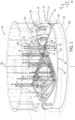
- FIG. 1 is a perspective view of an embodiment of a carousel ride system 10 that includes a lift system 12 having one or more annular tracks 14.
- the carousel ride system 10 also includes multiple figures 16 (e.g., seats for riders) each supported by or mounted on a respective support system 18 that includes a respective support post 20 (e.g., rigid post) and a respective bogie 22.
- the carousel ride system 10 also includes a rotatable platform 24 on which the riders travel (e.g., walk) to reach the multiple figures 16 during loading and unloading operations.
- Each support post 20 extends through a respective opening 26 in the rotatable platform 24, and thus, rotation of the rotatable platform 24 about an axis of rotation 28 (e.g., center axis) drives rotation of the multiple figures 16.
- an axis of rotation 28 e.g., center axis
- FIG. 1 To facilitate discussion and image clarity, only some of the multiple figures 16 and corresponding components (e.g., support systems 18) are illustrated in FIG. 1 . However, it should be appreciated that the multiple figures 16 and corresponding components may be distributed at various locations about the rotatable platform 24.
- the lift system 12 is in a ride position 30 (e.g., raised position) in which the one or more annular tracks 14 are raised relative to the rotatable platform 24 along a vertical axis 32 of the carousel ride system 10.
- the vertical axis 32 may be parallel to the axis of rotation 28.
- each of the one or more annular tracks 14 may extend through a respective annular gap 34 formed in a support frame 36 of the lift system 12.
- at least a portion of each of the one or more annular tracks 14 may be raised relative to the support frame 36 along the vertical axis 32.
- the bogies 22 may be supported on the one or more annular tracks 14.
- each of the bogies 22 may move along the one or more annular tracks 14.
- each of the bogies 22 may include one or more wheels 38 (e.g., center wheels) that contact a surface 40 (e.g., upper surface) of the one or more annular tracks 14 while the one or more annular tracks 14 are in the ride position 30, and then the one or more wheels 38 may move (e.g., roll) along the surface 40 of the one or more annular tracks 14 during rotation of the rotatable platform 24 during ride operations.
- the one or more annular tracks 14 may have undulations that extend circumferentially (e.g., along a circumferential axis 42) about the one or more annular tracks 14.
- the undulations cause the multiple figures 16 to move up and down along the vertical axis 32 relative to the rotatable platform 24 during ride operations.
- rotation of the rotatable platform 24 drives rotation of the multiple figures 16 and the attached respective support systems 18, thereby causing the bogies 22 to move along the undulations of the one or more annular tracks 14 to cause the multiple figures 16 to move up and down along the vertical axis 32 relative to the rotatable platform 24.
- each peak region 44 includes a first height 50 relative to the support frame 36 and/or valley regions 46 along the vertical axis 32.
- the peak regions 44 have varying heights relative to the support frame 36 and/or valley regions 46 along the vertical axis 32.
- the valley regions 46 are generally flush with a surface 52 (e.g., upper surface) of the support frame 36.
- some or all of the valley regions 46 may be offset (e.g., raised or lowered, by the same or varying degrees) relative to the surface 52 of the support frame 36 along the vertical axis 32.
- the lift system 12 may be generally hidden from the view of the riders.
- the one or more annular tracks 14, the support frame 36, and at least a portion of the support system 18 are positioned vertically below the rotatable platform 24, enclosed or covered by a cover 54, and/or positioned within a receptacle 56 (e.g., opening or hole) formed in the ground.
- a receptacle 56 e.g., opening or hole formed in the ground.
- While at least some portions of the rotatable platform 24, the cover 54, and the ground surrounding the receptacle 56 are shown as generally transparent to facilitate discussion and to enable visualization of components of the lift system 12, it should be appreciated that the rotatable platform 24, the cover 54, and the ground surrounding the receptacle 56 may not be transparent in order to hide the components of the lift system 12.
- annular tracks 14 are shown in the illustrated embodiment, it should be appreciated that any suitable number (e.g., 1, 2, 3, 4, 5, or more) of annular tracks 14 may be provided.
- the carousel ride system 10 may include a handle 58 or other structure for the rider to hold during the ride operations, the carousel ride system 10 may be devoid of any support posts that extend vertically above the multiple figures 16.
- the multiple figures 16 may only be supported by the respective support posts 20 that extend vertically below the multiple figures 16, and the multiple figures 16 may not be supported by any support posts that are suspended from a ceiling or frame structure vertically above the multiple figures 16.
- the carousel ride system 10 may include supports posts that extend vertically above the multiple figures 16 and that are suspended from or extend through a ceiling or frame structure vertically above the multiple figures 16.
- FIG. 2 is a perspective view of a portion of the carousel ride system 10 of FIG. 1 with the lift system 12 in the ride position 30.
- the multiple figures 16 are each supported by or mounted on the respective support system 18 that includes the respective support post 20 and the respective bogie 22.
- Each support post 20 extends through the respective opening 26 in the rotatable platform 24.
- each of the one or more annular tracks 14 may extend vertically above the respective annular gap 34 formed in the support frame 36 and the bogies 22 may be supported on the one or more annular tracks 14. Additionally, during rotation of the rotatable platform 24 during ride operations, each of the bogies 22 may move along the one or more annular tracks 14 (e.g., via the one or more wheels 38 that contact and move along the surface 40 of the one or more annular tracks 14).
- the one or more annular tracks 14 may have undulations that cause the multiple figures 16 to move up and down relative to the rotatable platform 24 along the vertical axis 32 during ride operations.
- the undulations may include the peak regions 44 and the valley regions 46.
- each peak region 44 includes the first height 50 relative to the support frame 36 and/or valley regions 46 along the vertical axis 32, and the valley regions 46 are generally flush with the surface 52 of the support frame 36.
- the peak regions 44 and the valley regions 46 may have any of a variety of shapes and dimensions.
- FIG. 3 is a perspective view of the portion of the carousel ride system 10 of FIG. 2 with the lift system 12 in a load/unload position 60 (e.g., lowered position).
- a load/unload position 60 e.g., lowered position.
- the one or more annular tracks 14 are lowered relative to the rotatable platform 24 along the vertical axis 32.
- each of the one or more annular tracks 14 are withdrawn from the respective annular gap 34 formed in the support frame 36. That is, each of the one or more annular tracks 14 is lowered relative to the support frame 36 along the vertical axis 32.
- each of the bogies 22 may be supported on the support frame 36.
- each of the bogies 22 may include one or more wheels 62 (e.g., outer wheels) that contact the surface 52 of the support frame 36.
- the one or more wheels 38 may not be supported on and/or may not contact the one or more annular tracks 14. Because the surface 52 of the support frame 36 is a flat surface that is parallel to the rotatable platform 24 and that is orthogonal relative to the vertical axis 32, each of the multiple figures 16 may be at a same vertical height 64 relative to the rotatable platform 24 along the vertical axis 32 while the lift system 12 is in the load/unload position 60.
- the carousel ride system 10 may continuously move between loading operations, ride operations, and unloading operations.
- the disclosed lift system 12 may enable efficient transition between loading operations, ride operations, and unloading operations, such as by making it easier for riders to climb onto and off of the multiple figures 16.
- the rotatable platform 24 may be stationary and the lift system 12 may be in the load/unload position 60 in which the one or more annular tracks 14 are withdrawn from the respective annular gaps 34 in the support frame 36.
- the multiple figures 16 are all at the same vertical height 64 relative to the rotatable platform 24 along the vertical axis 32.
- the lift system 12 may adjust to the ride position 30 in which the one or more annular tracks 14 extend through the respective annular gaps 34 in the support frame 36 and extend vertically above the support frame 36 relative to the vertical axis 32. Due to the undulations of the one or more annular tracks 14, the multiple figures 16 will then be at varying vertical heights relative to the rotatable platform 24 (e.g., a first figure of the multiple figures 16 may be positioned at one of the peaks 44 and will be at a first height, and a second figure of the multiple figures may be positioned at one of the valleys 46 and will be at a second height, and/or a third figure of the multiple figures may be positioned between one of the peaks 44 and one of the valleys 46 and will be at a third height).
- a first figure of the multiple figures 16 may be positioned at one of the peaks 44 and will be at a first height
- a second figure of the multiple figures may be positioned at one of the valleys 46 and will be at a second height
- the rotatable platform 24 may rotate, thereby driving rotation of the multiple figures 16 and causing the bogies 22 coupled to the multiple figures 16 to travel along the undulations of the one or more annular tracks 14. Accordingly, during the ride operations, the multiple figures 16 may rotate with the rotatable platform 24 and may also move up and down relative to the rotatable platform 24 along the vertical axis 32. Following the ride operations, the rotatable platform 24 may cease rotating and may move to a stationary position for unloading operations. Then, the lift system 12 may adjust to the load/unload position 60 in which the one or more annular tracks 14 are withdrawn from the respective annular gaps 34 in the support frame 36.
- the multiple figures 16 are all at the same vertical height 64 relative to the rotatable platform 24 along the vertical axis 32 to facilitate unloading of the carousel ride system 10.
- the above-described steps to transition between the loading operations, the ride operations, and the unloading operations may be carried out in any suitable order and/or simultaneously.
- the rotatable platform 24 may rotate prior to or while the lift system 12 adjusts to the ride position 30.
- the rotatable platform 24 may cease rotation or slow rotation after or while the lift system 12 adjusts to the load/unload position 60.
- a control system 70 may include a controller 72 having a processor 74 and a memory device 76.
- the controller 72 may provide control signals to one or more actuators 78 (e.g., linear actuators) to adjust the lift system 12 between the illustrated ride position 30 and the load/unload position 60 ( FIG. 3 ).
- the controller 72 may also provide control signals to one or more actuators 80 to drive rotation of the rotatable platform 24.
- the controller 72 may be configured to receive inputs via an input device 82 (e.g., from a ride operator) and to provide the control signals to the actuators 78, 80 in response to the inputs. For example, the controller 72 may receive an input that indicates that the riders have climbed onto the multiple figures 16 and that the loading operations are complete. In response, the controller 72 may provide the control signals to the one or more actuators 78 to adjust the lift system 12 to the ride position 30, and then at some subsequent time (e.g., after the lift system 12 reaches the ride position 30) the controller 72 may provide the control signals to the one or more actuators 80 to drive rotation of the rotatable platform 24. As noted above, the steps to transition between the loading operations and the ride operations may be carried out in any suitable order and/or simultaneously. For example, in response to receipt of the input that the loading operations are complete, the controller 72 may provide the control signals to the actuators 80 to drive rotation of the rotatable platform 24 prior to or while the lift system 12 adjusts to the ride position 30.
- Certain steps may be automated and/or controlled on a timer (e.g., timed schedule). For example, once rotation of the rotatable platform 24 commences, the rotation may continue for a time period (e.g., predetermined or operator-set time period, such as 1, 2, 3, 4, 5, or more minutes). When the time period ends, the controller 72 may provide the control signals to the one or more actuators 80 to stop rotation of the rotatable platform 24 and cause the rotatable platform 24 to assume a stationary position for unloading operations.
- a timer e.g., timed schedule. For example, once rotation of the rotatable platform 24 commences, the rotation may continue for a time period (e.g., predetermined or operator-set time period, such as 1, 2, 3, 4, 5, or more minutes).
- the controller 72 may provide the control signals to the one or more actuators 80 to stop rotation of the rotatable platform 24 and cause the rotatable platform 24 to assume a stationary position for unloading operations.
- the controller 72 may provide the control signals to the one or more actuators 78 to adjust the lift system 12 to the load/unload position 60 in which the one or more annular tracks 14 are withdrawn from the respective annular gaps 34 in the support frame 36.
- the steps to transition between the ride operations and the unloading operations may be carried out in any suitable order and/or simultaneously.
- the controller 72 may provide the control signals to the actuators 80 to stop or to slow rotation of the rotatable platform 24 after or while the lift system 12 adjusts to the load/unload position 60.
- the memory device 76 may include one or more tangible, non-transitory, computer-readable media that store instructions executable by the processor 74 and/or data (e.g., time periods).
- the memory device 76 may include random access memory (RAM), read only memory (ROM), rewritable non-volatile memory such as flash memory, hard drives, optical discs, and/or the like.
- the processor 74 may include one or more general purpose microprocessors, one or more application specific processors (ASICs), one or more field programmable gate arrays (FPGAs), or any combination thereof.
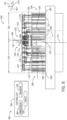
- FIG. 4 illustrates the various structural features of the carousel ride system 10 described above with respect to FIGS. 1-3 .
- FIG. 4 illustrates the multiple figures 16, the support systems 18 having the support posts 20 and the bogies 22, the rotatable platform 24, the cover 54, and the receptacle 56.
- FIG. 4 also illustrates the lift system 12 having the one or more annular tracks 14 and the support frame 36, for example.
- the various actuators 78, 80 are merely exemplary and any number and type of actuators may be positioned at any suitable locations about the carousel ride system 10 to enable the disclosed techniques.
- FIG. 5 is a perspective view of an embodiment of one of the bogies 22 that may be used in the carousel ride system 10.
- the bogie 22 includes multiple wheels 38 (e.g., two wheels arranged one in front of the other) that are configured to contact an upper surface of a respective one of the annular tracks 14 ( FIG. 4 ).
- the bogie 22 may also include multiple wheels 84 (e.g., two wheels arranged opposite to one another) that are configured to contact a side surface of the respective one of the annular tracks 14, thereby stabilizing the bogie 22 and the support post 20 coupled thereto during ride operations.
- the respective one of the annular tracks 14 may be received within a space 86 defined between the wheels 84 during ride operations.
- the bogie 22 also includes a bogie frame 88 that is coupled to the support post 20 and that supports the wheels 38, 84 (e.g., rotatably on respective axles).
- the bogie 22 also includes feet 90 (e.g., laterally-extending feet; arranged on opposite lateral sides of the bogie frame 88) that extend laterally-outwardly of the wheels 38, 84 and have respective surfaces (e.g., lower surfaces) that are configured to contact and rest upon the surface 52 of the support frame 36 ( FIG. 3 ) during the loading/unloading operations.
- FIG. 6 is a side view of an embodiment of a carousel ride system 100 that includes a lift system 102 having a shuttle assembly 104 (e.g., movable core).
- the carousel ride system 100 also includes multiple figures 106 (e.g., seats for riders) each supported by or mounted on a respective support system 108, which may include a respective support post 110 (e.g., rigid post) and/or a respective cable 112 (e.g., flexible cable).
- the carousel ride system 10 may also include a rotatable platform 114 on which the riders travel (e.g., walk) to reach the multiple figures 106 during loading and unloading operations.
- Each support post 110 may be coupled to the rotatable platform 114 and/or extend through a respective opening 116 in the rotatable platform 114, and thus, rotation of the rotatable platform 114 about an axis of rotation 117 (e.g., center axis) drives rotation of the multiple figures 106.
- an axis of rotation 117 e.g., center axis
- the lift system 102 is in a load/unload position 120 (e.g., centered position) in which the shuttle assembly 104 is centered (e.g., coaxial) relative to the rotatable platform 114, the multiple figures 106, and/or a center post 121 of the carousel ride system 100.
- the multiple figures 106 may be at a same vertical height 118 relative to the rotatable platform 114 along a vertical axis 123 of the carousel ride system 100.
- the vertical axis 123 may be parallel to the axis of rotation 117.
- each of the cables 112 extends over a respective first pulley 122 (e.g., sheave, hook, loop) coupled to and suspended from a ceiling structure 124 (e.g., frame) and a respective second pulley 126 (e.g., sheave, hook, loop) coupled to a support block 128 of the shuttle assembly 104.
- a respective first end 130 of each of the cables 112 may be coupled to the respective support post 110 and/or the respective figure 106, and a respective second end 132 of each of the cables 112 may be coupled to a plate 134 (e.g., lower plate, movable plate) of the shuttle assembly 104.
- an actuator 136 may be provided to adjust a vertical position of the plate 134, which in turn adjusts the vertical height of each of the multiple figures 106 relative to the rotatable platform 114 along the vertical axis 123.
- FIG. 7 is a side view of the carousel ride system 100 with the lift system 102 in an intermediate position 138. As shown, the actuator 136 may drive the plate 134 in the direction of an arrow 140 along the vertical axis 123 away from the support block 128 of the shuttle assembly 104 and toward the rotatable platform 114.
- the cables 112 are pulled over the pulleys 122, 126, thereby raising the multiple figures 106 relative to the rotatable platform 114 along the vertical axis 123 (e.g., raising all of the multiple figures 106 simultaneously to another same vertical height 142 relative to the rotatable platform 114 along the vertical axis 123).
- FIG. 8 is a side view of the carousel ride system 100 with the lift system 102 in a ride position 150 (e.g., laterally offset position).
- the shuttle assembly 104 is laterally offset relative to the rotatable platform 114, the multiple figures 106, and/or the center post 121 of the carousel ride system 100, along a lateral axis 153.
- the shuttle assembly 104 may be shifted laterally, such that a first distance 154 from an axis of rotation 156 (e.g., center axis) of the shuttle assembly 104 to a first edge point 158 of the rotatable platform 114 is different than a second distance 160 from the axis of rotation 156 of the shuttle assembly 104 to a second edge point 162 of the rotatable platform 114 that is diametrically opposite from the first edge point 158.
- the shuttle assembly 104 may be shifted laterally, such that the axis of rotation 117 of the rotatable platform 114 and the axis of rotation 156 of the shuttle assembly 104 are no longer aligned (e.g., not coaxial).
- the shuttle assembly 104 (including the pulleys 122, 126), the multiple figures 106, the support systems 108, and the rotatable platform 114 may rotate together in a circumferential direction 164.
- a distance 165 between each respective pair of the pulleys 122, 126 varies due to the laterally offset position of the shuttle assembly 104 and the attached second pulleys 126.
- the multiple figures 106 move up and down relative to the rotatable platform 114 along the vertical axis 123.
- each of the multiple figures 106 will be in a raised positioned (e.g., highest position relative to the rotatable platform 114) when on the first side 166 of the shuttle assembly 104 and will be in a lowered positioned (e.g., lowest position relative to the rotatable platform 114) when on the second side 168 of the shuttle assembly 104.
- FIG. 9 is a side cross-sectional view of the shuttle assembly 104
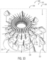
- FIG. 10 is a perspective view of the shuttle assembly 104.
- each of the cables 112 extends about the respective first pulley 122 and the respective second pulley 126.
- Each of the cables 112 includes the respective second end 132, which may have passed through the support block 128 to couple to the plate 134.
- the support block 128 may include a respective conduit or opening 170 for each of the cables 112, and the plate 134 may be a perforated plate with multiple openings 172 for each of the cables 112.
- the cables 112 may be covered by the support block 128 and/or securely attached to the plate 134 (e.g., by extending through the multiple openings 172 and attaching to a lower surface of the plate 134).
- the plate 134 is coupled to the actuator 136, which may raise and lower the plate 134 relative to the support block 128 to move the multiple figures 106 in the manner described with respect to FIG. 7 .
- the second pulleys 126 may be supported at discrete locations about the circumference of the support block 128 and are supported at multiple tiers (e.g., vertical levels or steps) of the support block 128. This configuration may enable the lift system 102 to adjust the position of a large number of figures 16 and resist cable entanglement.
- the carousel ride system 100 may continuously move between loading operations, ride operations, and unloading operations.
- the disclosed lift system 102 may enable efficient transition between loading operations, ride operations, and unloading operations, such as by making it easier for riders to climb onto and off of the multiple figures 16.
- the rotatable platform 114 may be stationary and the lift system 102 may be in the load/unload position 120 in which the shuttle assembly 104 is aligned with and centered relative to the rotatable platform 114.
- the multiple figures 106 are all at the same vertical height 118 relative to the rotatable platform 114 along the vertical axis 123.
- the lift system 102 may optionally adjust the multiple figures 16 to the intermediate position 138. Additionally or alternatively, the lift system 102 may adjust to the ride position 150 in which the shuttle assembly 104 is laterally offset from the rotatable platform 114, the multiple figures 106, and/or the center post 121 of the carousel ride system 100 along the lateral axis 153. Due to the laterally offset position of the shuttle assembly 104 and the resulting varying distances 65 between each respective pair of the pulleys 122, 126 during rotation, the multiple figures 106 may move up and down relative to the rotatable platform 114 along the vertical axis 123 during rotation.
- the laterally offset position of the shuttle assembly 104 may change during the ride operations.
- the shuttle assembly 104 may move to multiple different offset positions relative to the rotatable platform 114, the multiple figures 106, and/or the center post 121 of the carousel ride system 100 (e.g., at different distances from the centered position and/or at different locations about the circumference of the center post 121) during the ride operations.
- the laterally offset position and/or movement of the shuttle assembly 104 may vary during separate ride operations. Such configurations may provide a more varied and/or unpredictable up and down motion during the ride operations.
- the rotatable platform 114 may cease rotating and may move to a stationary position for unloading operations. Then, the lift system 102 may adjust to the load/unload position 120 by shifting the shuttle assembly 104 to be aligned with and centered relative to the rotatable platform 114.
- the multiple figures 106 e.g., all the multiple figures 106 that were raised and lowered by the lift system 102 during the ride operations
- the actuator 136 may adjust the plate 134 to move the multiple figures 106 to the another same vertical height 142 after the loading operations and prior to the ride operations. It should be appreciated that the above-described steps to transition between the loading operations, the ride operations, and the unloading operations may be carried out in any suitable order and/or simultaneously. For example, once the riders have climbed onto the multiple figures 106, the rotatable platform 114 may rotate prior to or while the lift system 102 adjusts to the ride position 150. Similarly, following the ride operations, the rotatable platform 114 may cease rotation or slow rotation after or while the lift system 102 adjusts to the load/unload position 120.
- a control system 180 may include a controller 182 having a processor 184 and a memory device 186.
- the controller 182 may provide control signals to one or more actuators, such as the actuator 136 to adjust the plate 134 as described above with respect to FIG. 7 .
- the controller 182 may provide control signals to one or more actuators 188 that drive the movement (e.g., lateral movement and/or rotation) of the shuttle assembly 104 to adjust the lift system 102 between the illustrated ride position 150 and the load/unload position 120 ( FIG. 6 ).
- the controller 182 may provide control signals to one or more actuators 190 that drive the rotation of the rotatable platform 114 and/or rotation of other components (e.g., the ceiling structure 124 and the attached first pulleys 122).
- the controller 182 may be configured to receive inputs via an input device 192 (e.g., from a ride operator) and to provide the control signals to the actuators 136, 188, 190 in response to the inputs.
- the controller 182 may receive an input that indicates that the riders have climbed on the multiple figures 106 and that the loading operations are complete.
- the controller 182 may provide the control signals to the one or more actuators 188 to adjust the lift system 102 to the ride position 150, and then at some subsequent time (e.g., after the lift system 102 reaches the ride position 150) the controller 182 may provide the control signals to the one or more actuators 188, 190 to drive rotation of the shuttle assembly 104, the rotatable platform 114, and the other components.
- the steps to transition between the loading operations and the ride operations may be carried out in any suitable order and/or simultaneously.
- the controller 182 may provide the control signals to the actuators 188, 190 to drive rotation of the components prior to or while the lift system 102 adjusts to the ride position 150.
- Certain steps may be automated and/or controlled on a timer (e.g., timed schedule). For example, once rotation of the rotatable platform 114 commences, the rotation may continue for a time period (e.g., predetermined or operator-set time period, such as 1, 2, 3, 4, 5, or more minutes). When the time period ends, the controller 182 may provide the control signals to the one or more actuators 188, 190 to stop rotation for unloading operations.
- a time period e.g., predetermined or operator-set time period, such as 1, 2, 3, 4, 5, or more minutes.
- the controller 182 may provide the control signals to the one or more actuators 188 to adjust the lift system 102 to the load/unload position 120 in which the shuttle assembly 104 is aligned with and centered relative to the rotatable platform 114.
- the steps to transition between the ride operations and the unloading operations may be carried out in any suitable order and/or simultaneously.
- the controller 182 may provide the control signals to the actuators 188, 190 to stop or to slow rotation of the rotatable platform 114 after or while the lift system 102 adjusts to the load/unload position 120.
- the various actuators 136, 188, 190 are merely exemplary and any number and type of actuators may be positioned at any suitable locations about the carousel ride system 100 to enable the disclosed techniques.
- the memory device 186 may include one or more tangible, non-transitory, computer-readable media that store instructions executable by the processor 184 and/or data (e.g., time periods).
- the memory device 186 may include random access memory (RAM), read only memory (ROM), rewritable non-volatile memory such as flash memory, hard drives, optical discs, and/or the like.
- the processor 184 may include one or more general purpose microprocessors, one or more application specific processors (ASICs), one or more field programmable gate arrays (FPGAs), or any combination thereof.
- FIG. 11 is a side view of an embodiment of a carousel ride system 200 that includes a lift system 202 having a plurality of actuators 204.
- the carousel ride system 200 also includes multiple figures 206 (e.g., seats for riders) each supported by or mounted on a respective support system 208, which may include a respective support post 210 (e.g., rigid post and/or flexible cable).
- the carousel ride system 200 may also include a rotatable platform 214 on which the riders travel (e.g., walk) to reach the multiple figures 206 during loading and unloading operations.
- Each support post 210 may be coupled to the rotatable platform 214 and/or extend through a respective opening 216 in the rotatable platform 214, and thus, rotation of the rotatable platform 214 about an axis of rotation (e.g., center axis) drives rotation of the multiple figures 206.
- an axis of rotation e.g., center axis
- Each of the plurality of actuators 204 may be configured to individually drive movement of one of the multiple figures 206.
- each of the plurality of actuators 204 may include a linear actuator that is supported by a ceiling structure 218 (e.g., frame) and that operates to raise and to lower the respective support post 210 and the attached respective figure 206 relative to the rotatable platform 214 as the rotatable platform 214 rotates during ride operations.
- a ceiling structure 218 e.g., frame
- each of the plurality of actuators 204 may include a rotary actuator that rotates a spool to alternately wind and unwind the respective support post 210 (e.g., flexible cable) to raise and to lower the respective figure 206 relative to the rotatable platform 214 as the rotatable platform 214 rotates during ride operations. It should be appreciated that the plurality of actuators 204 may be supported by or positioned at or vertically below the rotatable platform 214.
- the carousel ride system 200 may continuously move between loading operations, ride operations, and unloading operations.
- the disclosed lift system 202 may enable efficient transition between loading operations, ride operations, and unloading operations, such as by making it easier for riders to climb onto and off of the multiple figures 206.
- the rotatable platform 214 may be stationary and the lift system 202 may be in a load/unload position 220 in which the multiple figures 206 are positioned at a same vertical height 222 relative to the rotatable platform 214 along a vertical axis 224 of the carousel ride system 200.
- the vertical axis 224 may be parallel to the axis of rotation of the rotatable platform 224.
- the lift system 202 may operate the plurality of actuators 204 to move the multiple figures 206 up and down relative to the rotatable platform 214 along the vertical axis 123 during rotation of the rotatable platform 214.
- the rotatable platform 214 may cease rotating and may move to a stationary position for unloading operations.
- the lift system 202 may adjust to the load/unload position 220 to position the multiple figures 206 (e.g., all the multiple figures 206 that were raised and lowered by the lift system 202 during the ride operations) at the same vertical height 222 relative to the rotatable platform 214 along the vertical axis 224 to facilitate unloading of the carousel ride system 200.
- the multiple figures 206 e.g., all the multiple figures 206 that were raised and lowered by the lift system 202 during the ride operations
- the above-described steps to transition between the loading operations, the ride operations, and the unloading operations may be carried out in any suitable order and/or simultaneously.
- the rotatable platform 214 may rotate prior to or while the lift system 202 adjusts to the ride position.
- the rotatable platform 214 may cease rotation or slow rotation after or while the lift system 202 adjusts to the load/unload position 220.
- a control system 230 may include a controller 232 having a processor 234 and a memory device 236.
- the controller 232 may provide control signals to the plurality of actuators 204 to individually raise and lower the multiple figures 206.
- the controller 232 may also provide control signals to one or more actuators 238 that drive the rotation of the rotatable platform 214 and/or rotation of other components (e.g., the ceiling structure 218).
- the controller 232 may be configured to receive inputs via an input device 240 (e.g., from a ride operator) and to provide the control signals to the actuators 204, 238 in response to the inputs. For example, the controller 232 may receive an input that indicates that the riders have climbed on the multiple figures 206 and that the loading operations are complete. In response, the controller 232 may provide the control signals to the plurality of actuators 204 to raise and to lower the multiple figures 206 relative to the rotatable platform 214 and to the one or more actuators 238 to drive rotation of the rotatable platform 214 and the other components. As noted above, the steps to transition between the loading operations and the ride operations may be carried out in any suitable order and/or simultaneously.
- Certain steps may be automated and/or controlled on a timer (e.g., timed schedule). For example, once rotation of the rotatable platform 214 commences, the rotation may continue for a time period (e.g., predetermined or operator-set time period, such as 1, 2, 3, 4, 5, or more minutes). When the time period ends, the controller 232 may provide the control signals to the one or more actuators 238 to stop rotation for unloading operations. The controller 232 may also provide the control signals to the plurality of actuators 238 to adjust the lift system 202 to the load/unload position 220 in which the multiple figures 206 are all at the same vertical height 222 relative to the rotatable platform 214.
- a timer e.g., timed schedule
- the steps to transition between the ride operations and the unloading operations may be carried out in any suitable order and/or simultaneously.
- the various actuators 204, 238 are merely exemplary and any number and type of actuators may be positioned at any suitable locations about the carousel ride system 200 to enable the disclosed techniques.
- the memory device 236 may include one or more tangible, non-transitory, computer-readable media that store instructions executable by the processor 234 and/or data (e.g., time periods).
- the memory device 236 may include random access memory (RAM), read only memory (ROM), rewritable non-volatile memory such as flash memory, hard drives, optical discs, and/or the like.
- the processor 234 may include one or more general purpose microprocessors, one or more application specific processors (ASICs), one or more field programmable gate arrays (FPGAs), or any combination thereof.
- FIG. 12 is a flow diagram of an embodiment of a method 250 of operating a carousel ride system, including any of the carousel ride systems disclosed herein.
- the method 250 disclosed herein includes various steps represented by blocks. It should be noted that at least some steps of the method 250 may be performed as an automated procedure by a system, such as any of the control systems disclosed herein. Although the flow chart illustrates the steps in a certain sequence, it should be understood that the steps may be performed in any suitable order and certain steps may be carried out simultaneously, where appropriate. Additionally, steps may be added to or omitted from the method 250.
- a lift system may be controlled to position multiple figures at a same vertical height relative to a rotatable platform of a carousel ride system during loading operations.
- the lift system may be controlled to move the multiple figures up and down relative to the rotatable platform along a vertical axis during rotation of the rotatable platform and the multiple figures during ride operations.
- each of the multiple figures may be at varying vertical heights relative to the rotatable platform along the vertical axis during the ride operations.
- a respective vertical height of a first figure of the multiple figures may vary during the ride operations, and the respective vertical height of the first figure of the multiple figures may be different from a respective vertical height of a second figure of the multiple figures at certain times and/or throughout the ride operations.
- the lift system may be controlled to return the multiple figures to the same vertical height relative to the rotatable platform during unloading operations. Additional details of the method 250 may be understood with reference to FIGS. 1-11 and the corresponding description.
Landscapes
- Warehouses Or Storage Devices (AREA)
- Seats For Vehicles (AREA)
- Handcart (AREA)
- Motorcycle And Bicycle Frame (AREA)
- Forklifts And Lifting Vehicles (AREA)
- Jib Cranes (AREA)
- Rehabilitation Tools (AREA)
Claims (13)
- Karussellfahrsystem (10, 100, 200), umfassend:eine drehbare Plattform (24, 114, 214);eine Vielzahl von Figuren (16, 106, 206), die konfiguriert sind, um sich mit der drehbaren Plattform (24, 114, 214) zu drehen, wobei jede Figur (16, 106, 206) der Vielzahl von Figuren (16, 106, 206) auf einem jeweiligen Stützpfosten (20, 110, 210) abgestützt ist, die sich vertikal durch eine jeweilige Öffnung (26, 116, 216) in der drehbaren Plattform (24, 114, 214) erstreckt;
undein Hebesystem (12, 102, 202), umfassend eine ringförmige Bahn (14), die konfiguriert ist, um sich relativ zu der drehbaren Plattform (24, 114, 214) entlang einer vertikalen Achse (32, 123, 224) zu bewegen, wobei das Hebesystem konfiguriert ist, um die Vielzahl von Figuren (16, 106, 206) relativ zu der drehbaren Plattform (24, 114, 214) entlang der vertikalen Achse (32, 123, 224) während des Fahrbetriebs anzuheben und zu senken und die Vielzahl von Figuren (16, 106, 206) in einer gleichen vertikalen Höhe (64, 118, 142, 222) relativ zu der drehbaren Plattform (24, 114, 214) entlang der vertikalen Achse (32, 123, 224) während des Be- und Entladebetriebs zu positionieren. - Karussellfahrsystem (10, 100, 200) nach Anspruch 1, wobei die ringförmige Bahn (14) eine oder mehrere Wellungen umfasst, die sich in Umfangsrichtung um die ringförmige Bahn (14) erstrecken.
- Karussellfahrsystem (10, 100, 200) nach Anspruch 1, wobei der jeweilige Stützpfosten (20, 110, 210) mit einem jeweiligen Drehgestell (22) gekoppelt ist.
- Karussellfahrsystem (10, 100, 200) nach Anspruch 3, wobei das jeweilige Drehgestell (22) mindestens ein Rad (38, 62) umfasst, das konfiguriert ist, um während des Be- und Entladebetriebs auf einem Stützrahmen (36) gestützt zu werden, und mindestens ein anderes Rad (38, 62), das konfiguriert ist, um während des Fahrbetriebs auf der ringförmigen Bahn (14) gestützt zu werden.
- Karussellfahrsystem (10, 100, 200) nach Anspruch 1, wobei das Hebesystem (12, 102, 202) einen Stützrahmen (36) umfasst, der vertikal unterhalb der drehbaren Plattform (24) positioniert ist, wobei der Stützrahmen (36) einen ringförmigen Spalt (34) umfasst und die ringförmige Bahn (14) konfiguriert ist, um sich durch den ringförmigen Spalt (34) entlang der vertikalen Achse (32, 123, 224) zu bewegen.
- Karussellfahrsystem (10) nach Anspruch 1, wobei das Hebesystem (102) eine Pendelanordnung (104) umfasst, die konfiguriert ist, um während des Be- und Entladebetriebs in einer zentralen Position relativ zu einer Drehachse der drehbaren Plattform (114) zu sein, und die konfiguriert ist, um während des Fahrbetriebs in einer seitlich versetzten Position relativ zu der Drehachse der drehbaren Plattform (114) zu sein.
- Karussellfahrsystem (10) nach Anspruch 6, wobei das Hebesystem (102) eine Vielzahl von Rollen (122, 126) umfasst, die mit der Pendelanordnung (104) gekoppelt sind und eine Vielzahl von Kabeln (112) stützen, und jedes Kabel der Vielzahl von Kabeln (112) einen jeweiligen ersten Endabschnitt, der mit einer jeweiligen Figur der Vielzahl von Figuren (106) gekoppelt ist, und einen jeweiligen zweiten Endabschnitt umfasst, der mit der Pendelanordnung (104) gekoppelt ist.
- Karussellfahrsystem nach Anspruch 7, wobei der jeweilige erste Endabschnitt jedes Kabels der Vielzahl von Kabeln (112) über den jeweiligen Stützpfosten (110) mit der jeweiligen Figur der Vielzahl von Figuren (106) gekoppelt ist.
- Karussellfahrsystem (10, 100, 200) nach Anspruch 1, wobei das Hebesystem (12, 102, 202) eine Vielzahl von Aktuatoren umfasst und jeder der Vielzahl von Aktuatoren einer jeweiligen Figur (16, 106, 206) der Vielzahl von Figuren (16) zugeordnet ist und konfiguriert ist, um die Bewegung der jeweiligen Figur (16, 106, 206) der Vielzahl von Figuren (16, 106, 206) relativ zu der drehbaren Plattform (24, 114, 214) entlang der vertikalen Achse (32, 123, 224) unabhängig anzutreiben.
- Karussellfahrsystem nach Anspruch 9, wobei die Vielzahl von Aktuatoren mehrere lineare Aktuatoren umfassen.
- Karussellfahrsystem (10, 100, 200) nach Anspruch 1, wobei das Hebesystem (12, 102, 202) eine Steuerung (72, 182, 232) umfasst, und wobei die Steuerung (72, 182, 232) konfiguriert ist, um einen oder mehrere Aktuatoren des Hebesystems (12, 102, 202) zu steuern, um eine oder mehrere Komponenten des Hebesystems (12, 102, 202) einzustellen, um zu veranlassen, dass die Vielzahl von Figuren (16, 106, 206) sich während des Fahrbetriebs relativ zu der drehbaren Plattform (24, 114, 214) entlang der vertikalen Achse (32, 123, 224) wiederholt nach oben und unten bewegt und zu veranlassen, dass sich die Vielzahl von Figuren (16, 106, 206) während des Be- und Entladebetriebs relativ zu der drehbaren Plattform (24, 114, 214) auf derselben vertikalen Höhe (64, 118, 142, 222) befindet.
- Verfahren zum Betreiben eines Karussellfahrsystems (10, 100, 200), umfassend:i) Positionieren, unter Verwendung eines Hebesystems (12, 102, 202), einer Vielzahl von Figuren (16, 106, 206) auf einer gleichen vertikalen Höhe (64, 118, 142, 222) relativ zu einer drehbaren Plattform (24, 114, 214) entlang einer vertikalen Achse (32, 123, 224) während Ladevorgängen, wobei jede Figur (16, 106, 206) der Vielzahl von Figuren (16, 106, 206) auf einem jeweiligen Stützpfosten (20, 110, 210) gestützt wird, der sich vertikal durch eine jeweilige Öffnung (26, 116, 216) in der drehbaren Plattform (24, 114, 214) erstreckt;ii) Bewegen, unter Verwendung des Hebesystems (12, 102, 202), der Vielzahl von Figuren (16, 106, 206) nach oben und unten relativ zu der drehbaren Plattform (24, 114, 214) entlang der vertikalen Achse (32, 123, 224) während der Drehung der drehbaren Plattform (24, 114, 214) und der Vielzahl von Figuren (16, 106, 206) während des Fahrbetriebs; undiii) Positionieren, unter Verwendung des Hebesystems (12, 102, 202), der Vielzahl von Figuren (16, 106, 206) in die gleiche vertikale Position relativ zu der drehbaren Plattform (24, 114, 214) entlang der vertikalen Achse (32, 123, 224) während Entladevorgängen;wobei in den Schritten i), ii) und iii) das Verwenden des Hebesystems das Bewegen einer ringförmigen Bahn des Hebesystems (12, 102, 202) relativ zu der drehbaren Plattform (24, 114, 214) entlang der vertikalen Achse (32, 123, 224) umfasst.
- Verfahren nach Anspruch 12, umfassend das Rollen von Rädern (38, 62, 84) von Drehgestellen (22), die mit der Vielzahl von Figuren (16, 106, 206) gekoppelt sind, entlang der ringförmigen Bahn (14), um die Bewegung der Vielzahl von Figuren (16, 106, 206) nach oben und unten relativ zu der drehbaren Plattform (24, 114, 214) entlang der vertikalen Achse (32, 123, 224) während der Drehung der drehbaren Plattform (24, 114, 214) und der Vielzahl von Figuren (16, 106, 206) während des Fahrbetriebs zu ermöglichen.
Applications Claiming Priority (3)
| Application Number | Priority Date | Filing Date | Title |
|---|---|---|---|
| US201962820092P | 2019-03-18 | 2019-03-18 | |
| US16/821,448 US11161049B2 (en) | 2019-03-18 | 2020-03-17 | Carousel ride systems and methods |
| PCT/US2020/023271 WO2020191005A1 (en) | 2019-03-18 | 2020-03-18 | Carousel ride systems and methods |
Publications (2)
| Publication Number | Publication Date |
|---|---|
| EP3941603A1 EP3941603A1 (de) | 2022-01-26 |
| EP3941603B1 true EP3941603B1 (de) | 2024-05-01 |
Family
ID=72513860
Family Applications (1)
| Application Number | Title | Priority Date | Filing Date |
|---|---|---|---|
| EP20718478.9A Active EP3941603B1 (de) | 2019-03-18 | 2020-03-18 | Karussell und verfahren |
Country Status (10)
| Country | Link |
|---|---|
| US (1) | US11161049B2 (de) |
| EP (1) | EP3941603B1 (de) |
| JP (1) | JP7545988B2 (de) |
| KR (1) | KR102882211B1 (de) |
| CN (1) | CN113557071B (de) |
| CA (1) | CA3131885C (de) |
| ES (1) | ES2984301T3 (de) |
| MY (1) | MY208804A (de) |
| SG (1) | SG11202109165RA (de) |
| WO (1) | WO2020191005A1 (de) |
Family Cites Families (17)
| Publication number | Priority date | Publication date | Assignee | Title |
|---|---|---|---|---|
| US1399582A (en) | 1920-10-25 | 1921-12-06 | Sayih James | Amusement device |
| GB189916A (en) | 1921-09-27 | 1922-12-14 | John Robert Walker | Improvements in or relating to amusement appliances |
| GB437425A (en) * | 1935-05-03 | 1935-10-29 | Fairdom Ltd | Amusement apparatus |
| US2509944A (en) | 1946-08-23 | 1950-05-30 | Jack J Skelley | Undulating track roundabout |
| US3356365A (en) | 1963-11-29 | 1967-12-05 | Shano Alphonse D De | Carrousel with relatively movable track supporting cam members for selectively changing the track undulations |
| FR2203283A5 (de) | 1972-10-18 | 1974-05-10 | Fouche Michel | |
| US3985352A (en) | 1975-10-15 | 1976-10-12 | Nitzsche Merlin J | Rider propelled rotatable riding device |
| US4973042A (en) | 1990-01-22 | 1990-11-27 | Klopf Frank P | Tower amusement ride |
| JPH0956931A (ja) * | 1995-08-25 | 1997-03-04 | Masago Kogyo Kk | メリーゴーランド |
| US5617658A (en) * | 1995-11-22 | 1997-04-08 | Chen; Corrina | Carrousel |
| CN2395762Y (zh) * | 1999-10-09 | 2000-09-13 | 翁庆贤 | 设有旋转接头的游戏机 |
| US7666103B2 (en) | 2004-01-29 | 2010-02-23 | Cottingham Agencies Ltd. | Amusement ride |
| CN200945361Y (zh) * | 2006-12-31 | 2007-09-12 | 席风春 | 移动折叠式旋转木马 |
| US8313389B2 (en) | 2010-08-30 | 2012-11-20 | Disney Enterprises, Inc. | Ring carousel ride |
| US8517847B2 (en) * | 2011-09-06 | 2013-08-27 | Disney Enterprises, Inc. | Omnitable ride system |
| CN207532771U (zh) * | 2017-10-31 | 2018-06-26 | 广州市顺宏游乐设备有限公司 | 转盘式游乐设备 |
| CN208493213U (zh) | 2018-08-06 | 2019-02-15 | 郑州山之田模型艺术设计有限公司 | 一种旋转升降木马模型 |
-
2020
- 2020-03-17 US US16/821,448 patent/US11161049B2/en active Active
- 2020-03-18 CN CN202080022251.3A patent/CN113557071B/zh active Active
- 2020-03-18 SG SG11202109165RA patent/SG11202109165RA/en unknown
- 2020-03-18 CA CA3131885A patent/CA3131885C/en active Active
- 2020-03-18 MY MYPI2021004776A patent/MY208804A/en unknown
- 2020-03-18 JP JP2021556453A patent/JP7545988B2/ja active Active
- 2020-03-18 ES ES20718478T patent/ES2984301T3/es active Active
- 2020-03-18 KR KR1020217033629A patent/KR102882211B1/ko active Active
- 2020-03-18 WO PCT/US2020/023271 patent/WO2020191005A1/en not_active Ceased
- 2020-03-18 EP EP20718478.9A patent/EP3941603B1/de active Active
Also Published As
| Publication number | Publication date |
|---|---|
| WO2020191005A1 (en) | 2020-09-24 |
| CN113557071B (zh) | 2025-03-11 |
| ES2984301T3 (es) | 2024-10-29 |
| KR20210135605A (ko) | 2021-11-15 |
| MY208804A (en) | 2025-05-29 |
| CN113557071A (zh) | 2021-10-26 |
| JP2022525538A (ja) | 2022-05-17 |
| CA3131885C (en) | 2023-10-03 |
| EP3941603A1 (de) | 2022-01-26 |
| CA3131885A1 (en) | 2020-09-24 |
| SG11202109165RA (en) | 2021-09-29 |
| JP7545988B2 (ja) | 2024-09-05 |
| US20200298132A1 (en) | 2020-09-24 |
| US11161049B2 (en) | 2021-11-02 |
| KR102882211B1 (ko) | 2025-11-05 |
Similar Documents
| Publication | Publication Date | Title |
|---|---|---|
| US8517847B2 (en) | Omnitable ride system | |
| EP2422856B1 (de) | Ringkarussell-Fahrgeschäft | |
| CN113396000B (zh) | 场景隔室乘坐系统和方法 | |
| US11161049B2 (en) | Carousel ride systems and methods | |
| EP3902761B1 (de) | Fahrgeschäftsaufzug und bewegungsbetätigung | |
| HK40063586A (en) | Carousel ride systems and methods | |
| HK40063586B (zh) | 转盘式乘坐系统和方法 | |
| US20240408502A1 (en) | Round ride systems and methods | |
| US11918924B2 (en) | Carousel ride systems | |
| WO2024253892A1 (en) | Round ride systems and methods | |
| HK40062012A (en) | Scenic compartment ride systems and methods | |
| RU2021130045A (ru) | Системы и способы катания на карусели | |
| HK40062012B (zh) | 场景隔室乘坐系统和方法 |
Legal Events
| Date | Code | Title | Description |
|---|---|---|---|
| STAA | Information on the status of an ep patent application or granted ep patent |
Free format text: STATUS: UNKNOWN |
|
| STAA | Information on the status of an ep patent application or granted ep patent |
Free format text: STATUS: THE INTERNATIONAL PUBLICATION HAS BEEN MADE |
|
| PUAI | Public reference made under article 153(3) epc to a published international application that has entered the european phase |
Free format text: ORIGINAL CODE: 0009012 |
|
| STAA | Information on the status of an ep patent application or granted ep patent |
Free format text: STATUS: REQUEST FOR EXAMINATION WAS MADE |
|
| 17P | Request for examination filed |
Effective date: 20211004 |
|
| AK | Designated contracting states |
Kind code of ref document: A1 Designated state(s): AL AT BE BG CH CY CZ DE DK EE ES FI FR GB GR HR HU IE IS IT LI LT LU LV MC MK MT NL NO PL PT RO RS SE SI SK SM TR |
|
| DAV | Request for validation of the european patent (deleted) | ||
| DAX | Request for extension of the european patent (deleted) | ||
| STAA | Information on the status of an ep patent application or granted ep patent |
Free format text: STATUS: EXAMINATION IS IN PROGRESS |
|
| 17Q | First examination report despatched |
Effective date: 20230209 |
|
| REG | Reference to a national code |
Ipc: A63G0001340000 Ref country code: DE Ref legal event code: R079 Ref document number: 602020030125 Country of ref document: DE Free format text: PREVIOUS MAIN CLASS: A63G0001300000 Ipc: A63G0001340000 |
|
| RIC1 | Information provided on ipc code assigned before grant |
Ipc: A63G 1/10 20060101ALI20230912BHEP Ipc: A63G 1/34 20060101AFI20230912BHEP |
|
| GRAP | Despatch of communication of intention to grant a patent |
Free format text: ORIGINAL CODE: EPIDOSNIGR1 |
|
| STAA | Information on the status of an ep patent application or granted ep patent |
Free format text: STATUS: GRANT OF PATENT IS INTENDED |
|
| INTG | Intention to grant announced |
Effective date: 20231123 |
|
| GRAS | Grant fee paid |
Free format text: ORIGINAL CODE: EPIDOSNIGR3 |
|
| GRAA | (expected) grant |
Free format text: ORIGINAL CODE: 0009210 |
|
| STAA | Information on the status of an ep patent application or granted ep patent |
Free format text: STATUS: THE PATENT HAS BEEN GRANTED |
|
| AK | Designated contracting states |
Kind code of ref document: B1 Designated state(s): AL AT BE BG CH CY CZ DE DK EE ES FI FR GB GR HR HU IE IS IT LI LT LU LV MC MK MT NL NO PL PT RO RS SE SI SK SM TR |
|
| REG | Reference to a national code |
Ref country code: GB Ref legal event code: FG4D |
|
| REG | Reference to a national code |
Ref country code: CH Ref legal event code: EP |
|
| REG | Reference to a national code |
Ref country code: DE Ref legal event code: R096 Ref document number: 602020030125 Country of ref document: DE |
|
| REG | Reference to a national code |
Ref country code: IE Ref legal event code: FG4D |
|
| P01 | Opt-out of the competence of the unified patent court (upc) registered |
Effective date: 20240424 |
|
| REG | Reference to a national code |
Ref country code: LT Ref legal event code: MG9D |
|
| REG | Reference to a national code |
Ref country code: NL Ref legal event code: MP Effective date: 20240501 |
|
| PG25 | Lapsed in a contracting state [announced via postgrant information from national office to epo] |
Ref country code: IS Free format text: LAPSE BECAUSE OF FAILURE TO SUBMIT A TRANSLATION OF THE DESCRIPTION OR TO PAY THE FEE WITHIN THE PRESCRIBED TIME-LIMIT Effective date: 20240901 |
|
| PG25 | Lapsed in a contracting state [announced via postgrant information from national office to epo] |
Ref country code: BG Free format text: LAPSE BECAUSE OF FAILURE TO SUBMIT A TRANSLATION OF THE DESCRIPTION OR TO PAY THE FEE WITHIN THE PRESCRIBED TIME-LIMIT Effective date: 20240501 |
|
| PG25 | Lapsed in a contracting state [announced via postgrant information from national office to epo] |
Ref country code: FI Free format text: LAPSE BECAUSE OF FAILURE TO SUBMIT A TRANSLATION OF THE DESCRIPTION OR TO PAY THE FEE WITHIN THE PRESCRIBED TIME-LIMIT Effective date: 20240501 Ref country code: HR Free format text: LAPSE BECAUSE OF FAILURE TO SUBMIT A TRANSLATION OF THE DESCRIPTION OR TO PAY THE FEE WITHIN THE PRESCRIBED TIME-LIMIT Effective date: 20240501 |
|
| PG25 | Lapsed in a contracting state [announced via postgrant information from national office to epo] |
Ref country code: GR Free format text: LAPSE BECAUSE OF FAILURE TO SUBMIT A TRANSLATION OF THE DESCRIPTION OR TO PAY THE FEE WITHIN THE PRESCRIBED TIME-LIMIT Effective date: 20240802 |
|
| PG25 | Lapsed in a contracting state [announced via postgrant information from national office to epo] |
Ref country code: PT Free format text: LAPSE BECAUSE OF FAILURE TO SUBMIT A TRANSLATION OF THE DESCRIPTION OR TO PAY THE FEE WITHIN THE PRESCRIBED TIME-LIMIT Effective date: 20240902 |
|
| PG25 | Lapsed in a contracting state [announced via postgrant information from national office to epo] |
Ref country code: NL Free format text: LAPSE BECAUSE OF FAILURE TO SUBMIT A TRANSLATION OF THE DESCRIPTION OR TO PAY THE FEE WITHIN THE PRESCRIBED TIME-LIMIT Effective date: 20240501 |
|
| PG25 | Lapsed in a contracting state [announced via postgrant information from national office to epo] |
Ref country code: PL Free format text: LAPSE BECAUSE OF FAILURE TO SUBMIT A TRANSLATION OF THE DESCRIPTION OR TO PAY THE FEE WITHIN THE PRESCRIBED TIME-LIMIT Effective date: 20240501 |
|
| REG | Reference to a national code |
Ref country code: ES Ref legal event code: FG2A Ref document number: 2984301 Country of ref document: ES Kind code of ref document: T3 Effective date: 20241029 |
|
| PG25 | Lapsed in a contracting state [announced via postgrant information from national office to epo] |
Ref country code: LV Free format text: LAPSE BECAUSE OF FAILURE TO SUBMIT A TRANSLATION OF THE DESCRIPTION OR TO PAY THE FEE WITHIN THE PRESCRIBED TIME-LIMIT Effective date: 20240501 |
|
| PG25 | Lapsed in a contracting state [announced via postgrant information from national office to epo] |
Ref country code: PT Free format text: LAPSE BECAUSE OF FAILURE TO SUBMIT A TRANSLATION OF THE DESCRIPTION OR TO PAY THE FEE WITHIN THE PRESCRIBED TIME-LIMIT Effective date: 20240902 Ref country code: PL Free format text: LAPSE BECAUSE OF FAILURE TO SUBMIT A TRANSLATION OF THE DESCRIPTION OR TO PAY THE FEE WITHIN THE PRESCRIBED TIME-LIMIT Effective date: 20240501 Ref country code: NO Free format text: LAPSE BECAUSE OF FAILURE TO SUBMIT A TRANSLATION OF THE DESCRIPTION OR TO PAY THE FEE WITHIN THE PRESCRIBED TIME-LIMIT Effective date: 20240801 Ref country code: NL Free format text: LAPSE BECAUSE OF FAILURE TO SUBMIT A TRANSLATION OF THE DESCRIPTION OR TO PAY THE FEE WITHIN THE PRESCRIBED TIME-LIMIT Effective date: 20240501 Ref country code: LV Free format text: LAPSE BECAUSE OF FAILURE TO SUBMIT A TRANSLATION OF THE DESCRIPTION OR TO PAY THE FEE WITHIN THE PRESCRIBED TIME-LIMIT Effective date: 20240501 Ref country code: IS Free format text: LAPSE BECAUSE OF FAILURE TO SUBMIT A TRANSLATION OF THE DESCRIPTION OR TO PAY THE FEE WITHIN THE PRESCRIBED TIME-LIMIT Effective date: 20240901 Ref country code: HR Free format text: LAPSE BECAUSE OF FAILURE TO SUBMIT A TRANSLATION OF THE DESCRIPTION OR TO PAY THE FEE WITHIN THE PRESCRIBED TIME-LIMIT Effective date: 20240501 Ref country code: GR Free format text: LAPSE BECAUSE OF FAILURE TO SUBMIT A TRANSLATION OF THE DESCRIPTION OR TO PAY THE FEE WITHIN THE PRESCRIBED TIME-LIMIT Effective date: 20240802 Ref country code: FI Free format text: LAPSE BECAUSE OF FAILURE TO SUBMIT A TRANSLATION OF THE DESCRIPTION OR TO PAY THE FEE WITHIN THE PRESCRIBED TIME-LIMIT Effective date: 20240501 Ref country code: BG Free format text: LAPSE BECAUSE OF FAILURE TO SUBMIT A TRANSLATION OF THE DESCRIPTION OR TO PAY THE FEE WITHIN THE PRESCRIBED TIME-LIMIT Effective date: 20240501 Ref country code: RS Free format text: LAPSE BECAUSE OF FAILURE TO SUBMIT A TRANSLATION OF THE DESCRIPTION OR TO PAY THE FEE WITHIN THE PRESCRIBED TIME-LIMIT Effective date: 20240801 |
|
| PG25 | Lapsed in a contracting state [announced via postgrant information from national office to epo] |
Ref country code: DK Free format text: LAPSE BECAUSE OF FAILURE TO SUBMIT A TRANSLATION OF THE DESCRIPTION OR TO PAY THE FEE WITHIN THE PRESCRIBED TIME-LIMIT Effective date: 20240501 |
|
| PG25 | Lapsed in a contracting state [announced via postgrant information from national office to epo] |
Ref country code: EE Free format text: LAPSE BECAUSE OF FAILURE TO SUBMIT A TRANSLATION OF THE DESCRIPTION OR TO PAY THE FEE WITHIN THE PRESCRIBED TIME-LIMIT Effective date: 20240501 |
|
| PG25 | Lapsed in a contracting state [announced via postgrant information from national office to epo] |
Ref country code: CZ Free format text: LAPSE BECAUSE OF FAILURE TO SUBMIT A TRANSLATION OF THE DESCRIPTION OR TO PAY THE FEE WITHIN THE PRESCRIBED TIME-LIMIT Effective date: 20240501 |
|
| PG25 | Lapsed in a contracting state [announced via postgrant information from national office to epo] |
Ref country code: SK Free format text: LAPSE BECAUSE OF FAILURE TO SUBMIT A TRANSLATION OF THE DESCRIPTION OR TO PAY THE FEE WITHIN THE PRESCRIBED TIME-LIMIT Effective date: 20240501 Ref country code: RO Free format text: LAPSE BECAUSE OF FAILURE TO SUBMIT A TRANSLATION OF THE DESCRIPTION OR TO PAY THE FEE WITHIN THE PRESCRIBED TIME-LIMIT Effective date: 20240501 |
|
| PG25 | Lapsed in a contracting state [announced via postgrant information from national office to epo] |
Ref country code: SM Free format text: LAPSE BECAUSE OF FAILURE TO SUBMIT A TRANSLATION OF THE DESCRIPTION OR TO PAY THE FEE WITHIN THE PRESCRIBED TIME-LIMIT Effective date: 20240501 |
|
| PG25 | Lapsed in a contracting state [announced via postgrant information from national office to epo] |
Ref country code: SM Free format text: LAPSE BECAUSE OF FAILURE TO SUBMIT A TRANSLATION OF THE DESCRIPTION OR TO PAY THE FEE WITHIN THE PRESCRIBED TIME-LIMIT Effective date: 20240501 Ref country code: SK Free format text: LAPSE BECAUSE OF FAILURE TO SUBMIT A TRANSLATION OF THE DESCRIPTION OR TO PAY THE FEE WITHIN THE PRESCRIBED TIME-LIMIT Effective date: 20240501 Ref country code: RO Free format text: LAPSE BECAUSE OF FAILURE TO SUBMIT A TRANSLATION OF THE DESCRIPTION OR TO PAY THE FEE WITHIN THE PRESCRIBED TIME-LIMIT Effective date: 20240501 Ref country code: EE Free format text: LAPSE BECAUSE OF FAILURE TO SUBMIT A TRANSLATION OF THE DESCRIPTION OR TO PAY THE FEE WITHIN THE PRESCRIBED TIME-LIMIT Effective date: 20240501 Ref country code: DK Free format text: LAPSE BECAUSE OF FAILURE TO SUBMIT A TRANSLATION OF THE DESCRIPTION OR TO PAY THE FEE WITHIN THE PRESCRIBED TIME-LIMIT Effective date: 20240501 Ref country code: CZ Free format text: LAPSE BECAUSE OF FAILURE TO SUBMIT A TRANSLATION OF THE DESCRIPTION OR TO PAY THE FEE WITHIN THE PRESCRIBED TIME-LIMIT Effective date: 20240501 |
|
| REG | Reference to a national code |
Ref country code: DE Ref legal event code: R097 Ref document number: 602020030125 Country of ref document: DE |
|
| PLBE | No opposition filed within time limit |
Free format text: ORIGINAL CODE: 0009261 |
|
| STAA | Information on the status of an ep patent application or granted ep patent |
Free format text: STATUS: NO OPPOSITION FILED WITHIN TIME LIMIT |
|
| 26N | No opposition filed |
Effective date: 20250204 |
|
| PG25 | Lapsed in a contracting state [announced via postgrant information from national office to epo] |
Ref country code: SI Free format text: LAPSE BECAUSE OF FAILURE TO SUBMIT A TRANSLATION OF THE DESCRIPTION OR TO PAY THE FEE WITHIN THE PRESCRIBED TIME-LIMIT Effective date: 20240501 |
|
| PGFP | Annual fee paid to national office [announced via postgrant information from national office to epo] |
Ref country code: ES Payment date: 20250401 Year of fee payment: 6 |
|
| PGFP | Annual fee paid to national office [announced via postgrant information from national office to epo] |
Ref country code: CH Payment date: 20250401 Year of fee payment: 6 |
|
| PG25 | Lapsed in a contracting state [announced via postgrant information from national office to epo] |
Ref country code: SE Free format text: LAPSE BECAUSE OF FAILURE TO SUBMIT A TRANSLATION OF THE DESCRIPTION OR TO PAY THE FEE WITHIN THE PRESCRIBED TIME-LIMIT Effective date: 20240501 |
|
| PG25 | Lapsed in a contracting state [announced via postgrant information from national office to epo] |
Ref country code: MC Free format text: LAPSE BECAUSE OF FAILURE TO SUBMIT A TRANSLATION OF THE DESCRIPTION OR TO PAY THE FEE WITHIN THE PRESCRIBED TIME-LIMIT Effective date: 20240501 |
|
| REG | Reference to a national code |
Ref country code: AT Ref legal event code: UEP Ref document number: 1681556 Country of ref document: AT Kind code of ref document: T Effective date: 20240501 |
|
| PG25 | Lapsed in a contracting state [announced via postgrant information from national office to epo] |
Ref country code: LU Free format text: LAPSE BECAUSE OF NON-PAYMENT OF DUE FEES Effective date: 20250318 |
|
| REG | Reference to a national code |
Ref country code: BE Ref legal event code: MM Effective date: 20250331 |
|
| PG25 | Lapsed in a contracting state [announced via postgrant information from national office to epo] |
Ref country code: BE Free format text: LAPSE BECAUSE OF NON-PAYMENT OF DUE FEES Effective date: 20250331 |
|
| PG25 | Lapsed in a contracting state [announced via postgrant information from national office to epo] |
Ref country code: IE Free format text: LAPSE BECAUSE OF NON-PAYMENT OF DUE FEES Effective date: 20250318 |
|
| REG | Reference to a national code |
Ref country code: CH Ref legal event code: U11 Free format text: ST27 STATUS EVENT CODE: U-0-0-U10-U11 (AS PROVIDED BY THE NATIONAL OFFICE) Effective date: 20260401 |
|
| PGFP | Annual fee paid to national office [announced via postgrant information from national office to epo] |
Ref country code: GB Payment date: 20260327 Year of fee payment: 7 |
|
| PGFP | Annual fee paid to national office [announced via postgrant information from national office to epo] |
Ref country code: DE Payment date: 20260327 Year of fee payment: 7 |
|
| PGFP | Annual fee paid to national office [announced via postgrant information from national office to epo] |
Ref country code: AT Payment date: 20260327 Year of fee payment: 7 |
|
| PGFP | Annual fee paid to national office [announced via postgrant information from national office to epo] |
Ref country code: IT Payment date: 20260319 Year of fee payment: 7 |
|
| PGFP | Annual fee paid to national office [announced via postgrant information from national office to epo] |
Ref country code: FR Payment date: 20260325 Year of fee payment: 7 |