EP3940935A1 - Converter using planar transformer - Google Patents
Converter using planar transformer Download PDFInfo
- Publication number
- EP3940935A1 EP3940935A1 EP20205656.0A EP20205656A EP3940935A1 EP 3940935 A1 EP3940935 A1 EP 3940935A1 EP 20205656 A EP20205656 A EP 20205656A EP 3940935 A1 EP3940935 A1 EP 3940935A1
- Authority
- EP
- European Patent Office
- Prior art keywords
- inductor
- planar transformer
- current path
- transformer
- voltage
- Prior art date
- Legal status (The legal status is an assumption and is not a legal conclusion. Google has not performed a legal analysis and makes no representation as to the accuracy of the status listed.)
- Pending
Links
- 238000004804 winding Methods 0.000 claims abstract description 45
- 239000003990 capacitor Substances 0.000 claims description 8
- 239000000696 magnetic material Substances 0.000 claims description 2
- 238000010586 diagram Methods 0.000 description 9
- 238000006243 chemical reaction Methods 0.000 description 5
- 238000005516 engineering process Methods 0.000 description 2
- 230000004907 flux Effects 0.000 description 2
- 239000011888 foil Substances 0.000 description 2
- 239000000446 fuel Substances 0.000 description 2
- RYGMFSIKBFXOCR-UHFFFAOYSA-N Copper Chemical compound [Cu] RYGMFSIKBFXOCR-UHFFFAOYSA-N 0.000 description 1
- 239000004593 Epoxy Substances 0.000 description 1
- BQCADISMDOOEFD-UHFFFAOYSA-N Silver Chemical compound [Ag] BQCADISMDOOEFD-UHFFFAOYSA-N 0.000 description 1
- 238000003915 air pollution Methods 0.000 description 1
- 229910052782 aluminium Inorganic materials 0.000 description 1
- XAGFODPZIPBFFR-UHFFFAOYSA-N aluminium Chemical compound [Al] XAGFODPZIPBFFR-UHFFFAOYSA-N 0.000 description 1
- 239000004020 conductor Substances 0.000 description 1
- 239000011889 copper foil Substances 0.000 description 1
- 230000000694 effects Effects 0.000 description 1
- 230000005674 electromagnetic induction Effects 0.000 description 1
- 229910052751 metal Inorganic materials 0.000 description 1
- 239000002184 metal Substances 0.000 description 1
- 229910044991 metal oxide Inorganic materials 0.000 description 1
- 150000004706 metal oxides Chemical class 0.000 description 1
- 238000012986 modification Methods 0.000 description 1
- 230000004048 modification Effects 0.000 description 1
- 230000009466 transformation Effects 0.000 description 1
Images




Classifications
-
- H—ELECTRICITY
- H02—GENERATION; CONVERSION OR DISTRIBUTION OF ELECTRIC POWER
- H02M—APPARATUS FOR CONVERSION BETWEEN AC AND AC, BETWEEN AC AND DC, OR BETWEEN DC AND DC, AND FOR USE WITH MAINS OR SIMILAR POWER SUPPLY SYSTEMS; CONVERSION OF DC OR AC INPUT POWER INTO SURGE OUTPUT POWER; CONTROL OR REGULATION THEREOF
- H02M3/00—Conversion of DC power input into DC power output
- H02M3/02—Conversion of DC power input into DC power output without intermediate conversion into AC
- H02M3/04—Conversion of DC power input into DC power output without intermediate conversion into AC by static converters
- H02M3/10—Conversion of DC power input into DC power output without intermediate conversion into AC by static converters using discharge tubes with control electrode or semiconductor devices with control electrode
- H02M3/145—Conversion of DC power input into DC power output without intermediate conversion into AC by static converters using discharge tubes with control electrode or semiconductor devices with control electrode using devices of a triode or transistor type requiring continuous application of a control signal
- H02M3/155—Conversion of DC power input into DC power output without intermediate conversion into AC by static converters using discharge tubes with control electrode or semiconductor devices with control electrode using devices of a triode or transistor type requiring continuous application of a control signal using semiconductor devices only
- H02M3/156—Conversion of DC power input into DC power output without intermediate conversion into AC by static converters using discharge tubes with control electrode or semiconductor devices with control electrode using devices of a triode or transistor type requiring continuous application of a control signal using semiconductor devices only with automatic control of output voltage or current, e.g. switching regulators
- H02M3/158—Conversion of DC power input into DC power output without intermediate conversion into AC by static converters using discharge tubes with control electrode or semiconductor devices with control electrode using devices of a triode or transistor type requiring continuous application of a control signal using semiconductor devices only with automatic control of output voltage or current, e.g. switching regulators including plural semiconductor devices as final control devices for a single load
- H02M3/1588—Conversion of DC power input into DC power output without intermediate conversion into AC by static converters using discharge tubes with control electrode or semiconductor devices with control electrode using devices of a triode or transistor type requiring continuous application of a control signal using semiconductor devices only with automatic control of output voltage or current, e.g. switching regulators including plural semiconductor devices as final control devices for a single load comprising at least one synchronous rectifier element
-
- H—ELECTRICITY
- H02—GENERATION; CONVERSION OR DISTRIBUTION OF ELECTRIC POWER
- H02M—APPARATUS FOR CONVERSION BETWEEN AC AND AC, BETWEEN AC AND DC, OR BETWEEN DC AND DC, AND FOR USE WITH MAINS OR SIMILAR POWER SUPPLY SYSTEMS; CONVERSION OF DC OR AC INPUT POWER INTO SURGE OUTPUT POWER; CONTROL OR REGULATION THEREOF
- H02M3/00—Conversion of DC power input into DC power output
- H02M3/22—Conversion of DC power input into DC power output with intermediate conversion into AC
- H02M3/24—Conversion of DC power input into DC power output with intermediate conversion into AC by static converters
- H02M3/28—Conversion of DC power input into DC power output with intermediate conversion into AC by static converters using discharge tubes with control electrode or semiconductor devices with control electrode to produce the intermediate AC
- H02M3/325—Conversion of DC power input into DC power output with intermediate conversion into AC by static converters using discharge tubes with control electrode or semiconductor devices with control electrode to produce the intermediate AC using devices of a triode or a transistor type requiring continuous application of a control signal
- H02M3/335—Conversion of DC power input into DC power output with intermediate conversion into AC by static converters using discharge tubes with control electrode or semiconductor devices with control electrode to produce the intermediate AC using devices of a triode or a transistor type requiring continuous application of a control signal using semiconductor devices only
- H02M3/33569—Conversion of DC power input into DC power output with intermediate conversion into AC by static converters using discharge tubes with control electrode or semiconductor devices with control electrode to produce the intermediate AC using devices of a triode or a transistor type requiring continuous application of a control signal using semiconductor devices only having several active switching elements
-
- H—ELECTRICITY
- H01—ELECTRIC ELEMENTS
- H01F—MAGNETS; INDUCTANCES; TRANSFORMERS; SELECTION OF MATERIALS FOR THEIR MAGNETIC PROPERTIES
- H01F17/00—Fixed inductances of the signal type
- H01F17/0006—Printed inductances
-
- H—ELECTRICITY
- H01—ELECTRIC ELEMENTS
- H01F—MAGNETS; INDUCTANCES; TRANSFORMERS; SELECTION OF MATERIALS FOR THEIR MAGNETIC PROPERTIES
- H01F27/00—Details of transformers or inductances, in general
- H01F27/24—Magnetic cores
-
- H—ELECTRICITY
- H01—ELECTRIC ELEMENTS
- H01F—MAGNETS; INDUCTANCES; TRANSFORMERS; SELECTION OF MATERIALS FOR THEIR MAGNETIC PROPERTIES
- H01F27/00—Details of transformers or inductances, in general
- H01F27/24—Magnetic cores
- H01F27/26—Fastening parts of the core together; Fastening or mounting the core on casing or support
- H01F27/263—Fastening parts of the core together
-
- H—ELECTRICITY
- H01—ELECTRIC ELEMENTS
- H01F—MAGNETS; INDUCTANCES; TRANSFORMERS; SELECTION OF MATERIALS FOR THEIR MAGNETIC PROPERTIES
- H01F27/00—Details of transformers or inductances, in general
- H01F27/28—Coils; Windings; Conductive connections
- H01F27/2804—Printed windings
-
- H—ELECTRICITY
- H01—ELECTRIC ELEMENTS
- H01F—MAGNETS; INDUCTANCES; TRANSFORMERS; SELECTION OF MATERIALS FOR THEIR MAGNETIC PROPERTIES
- H01F27/00—Details of transformers or inductances, in general
- H01F27/28—Coils; Windings; Conductive connections
- H01F27/32—Insulating of coils, windings, or parts thereof
-
- H—ELECTRICITY
- H01—ELECTRIC ELEMENTS
- H01F—MAGNETS; INDUCTANCES; TRANSFORMERS; SELECTION OF MATERIALS FOR THEIR MAGNETIC PROPERTIES
- H01F27/00—Details of transformers or inductances, in general
- H01F27/33—Arrangements for noise damping
-
- H—ELECTRICITY
- H01—ELECTRIC ELEMENTS
- H01F—MAGNETS; INDUCTANCES; TRANSFORMERS; SELECTION OF MATERIALS FOR THEIR MAGNETIC PROPERTIES
- H01F5/00—Coils
- H01F5/003—Printed circuit coils
-
- H—ELECTRICITY
- H02—GENERATION; CONVERSION OR DISTRIBUTION OF ELECTRIC POWER
- H02M—APPARATUS FOR CONVERSION BETWEEN AC AND AC, BETWEEN AC AND DC, OR BETWEEN DC AND DC, AND FOR USE WITH MAINS OR SIMILAR POWER SUPPLY SYSTEMS; CONVERSION OF DC OR AC INPUT POWER INTO SURGE OUTPUT POWER; CONTROL OR REGULATION THEREOF
- H02M3/00—Conversion of DC power input into DC power output
- H02M3/22—Conversion of DC power input into DC power output with intermediate conversion into AC
- H02M3/24—Conversion of DC power input into DC power output with intermediate conversion into AC by static converters
- H02M3/28—Conversion of DC power input into DC power output with intermediate conversion into AC by static converters using discharge tubes with control electrode or semiconductor devices with control electrode to produce the intermediate AC
- H02M3/325—Conversion of DC power input into DC power output with intermediate conversion into AC by static converters using discharge tubes with control electrode or semiconductor devices with control electrode to produce the intermediate AC using devices of a triode or a transistor type requiring continuous application of a control signal
- H02M3/335—Conversion of DC power input into DC power output with intermediate conversion into AC by static converters using discharge tubes with control electrode or semiconductor devices with control electrode to produce the intermediate AC using devices of a triode or a transistor type requiring continuous application of a control signal using semiconductor devices only
-
- H—ELECTRICITY
- H01—ELECTRIC ELEMENTS
- H01F—MAGNETS; INDUCTANCES; TRANSFORMERS; SELECTION OF MATERIALS FOR THEIR MAGNETIC PROPERTIES
- H01F27/00—Details of transformers or inductances, in general
- H01F27/06—Mounting, supporting or suspending transformers, reactors or choke coils not being of the signal type
- H01F2027/065—Mounting on printed circuit boards
-
- H—ELECTRICITY
- H01—ELECTRIC ELEMENTS
- H01F—MAGNETS; INDUCTANCES; TRANSFORMERS; SELECTION OF MATERIALS FOR THEIR MAGNETIC PROPERTIES
- H01F27/00—Details of transformers or inductances, in general
- H01F27/28—Coils; Windings; Conductive connections
- H01F27/2804—Printed windings
- H01F2027/2809—Printed windings on stacked layers
-
- H—ELECTRICITY
- H01—ELECTRIC ELEMENTS
- H01F—MAGNETS; INDUCTANCES; TRANSFORMERS; SELECTION OF MATERIALS FOR THEIR MAGNETIC PROPERTIES
- H01F27/00—Details of transformers or inductances, in general
- H01F27/28—Coils; Windings; Conductive connections
- H01F27/2804—Printed windings
- H01F2027/2819—Planar transformers with printed windings, e.g. surrounded by two cores and to be mounted on printed circuit
-
- H—ELECTRICITY
- H02—GENERATION; CONVERSION OR DISTRIBUTION OF ELECTRIC POWER
- H02M—APPARATUS FOR CONVERSION BETWEEN AC AND AC, BETWEEN AC AND DC, OR BETWEEN DC AND DC, AND FOR USE WITH MAINS OR SIMILAR POWER SUPPLY SYSTEMS; CONVERSION OF DC OR AC INPUT POWER INTO SURGE OUTPUT POWER; CONTROL OR REGULATION THEREOF
- H02M1/00—Details of apparatus for conversion
- H02M1/0064—Magnetic structures combining different functions, e.g. storage, filtering or transformation
-
- H—ELECTRICITY
- H02—GENERATION; CONVERSION OR DISTRIBUTION OF ELECTRIC POWER
- H02M—APPARATUS FOR CONVERSION BETWEEN AC AND AC, BETWEEN AC AND DC, OR BETWEEN DC AND DC, AND FOR USE WITH MAINS OR SIMILAR POWER SUPPLY SYSTEMS; CONVERSION OF DC OR AC INPUT POWER INTO SURGE OUTPUT POWER; CONTROL OR REGULATION THEREOF
- H02M1/00—Details of apparatus for conversion
- H02M1/32—Means for protecting converters other than automatic disconnection
- H02M1/34—Snubber circuits
- H02M1/342—Active non-dissipative snubbers
-
- Y—GENERAL TAGGING OF NEW TECHNOLOGICAL DEVELOPMENTS; GENERAL TAGGING OF CROSS-SECTIONAL TECHNOLOGIES SPANNING OVER SEVERAL SECTIONS OF THE IPC; TECHNICAL SUBJECTS COVERED BY FORMER USPC CROSS-REFERENCE ART COLLECTIONS [XRACs] AND DIGESTS
- Y02—TECHNOLOGIES OR APPLICATIONS FOR MITIGATION OR ADAPTATION AGAINST CLIMATE CHANGE
- Y02B—CLIMATE CHANGE MITIGATION TECHNOLOGIES RELATED TO BUILDINGS, e.g. HOUSING, HOUSE APPLIANCES OR RELATED END-USER APPLICATIONS
- Y02B70/00—Technologies for an efficient end-user side electric power management and consumption
- Y02B70/10—Technologies improving the efficiency by using switched-mode power supplies [SMPS], i.e. efficient power electronics conversion e.g. power factor correction or reduction of losses in power supplies or efficient standby modes
Definitions
- the present disclosure relates to a DC-DC converter using a planar transformer.
- the eco-friendly vehicles include hybrid electric vehicles, fuel cell electric vehicles, and electric vehicles.
- the eco-friendly vehicles include a high voltage battery for driving a vehicle and a low voltage battery for driving electrical equipment.
- the electric energy charged in the high voltage battery is used as a power source for the vehicle, and the electric energy charged in the low voltage battery is used as the power source for the electrical equipment in the vehicle.
- An aspect of the present disclosure provides a converter using a planar transformer.
- a converter using a planar transformer includes an input device that receives a high voltage, a transformer including a first planar transformer and a second planar transformer that reduce a voltage provided from the input device, and an output device that outputs a voltage that is reduced by the transformer as a low voltage, and the input device provides a current to a primary winding coil of each of the first planar transformer and the second planar transformer through a first current path and a second current path in which current directions are different with each other, and includes a plurality of inductors connected in parallel with the primary winding coil of each of the first planar transformer and the second planar transformer.
- FIG. 1 is a diagram illustrating an actual configuration of a converter in some forms of the present disclosure.
- a converter may be implemented inside a vehicle.
- a converter may be integrally formed with the internal control units of the vehicle, and may be implemented as a separate device and may be connected to control units of the vehicle by separate connection means.
- a converter may include a circuit board, an input device, a transformer, and an output device.
- the input device, the transformer, and the output device may be mounted on the circuit board.
- the input device may receive a high voltage and may transfer the received high voltage to the transformer. In this case, the input device may reduce and transfer a noise component included in the high voltage when the high voltage is transferred to the transformer.
- the transformer may convert the high voltage to a low voltage by lowering the voltage level of the high voltage transferred from the input device.
- the transformer may include a first planar transformer and a second planar transformer, and the first planar transformer and the second planar transformer may convert the high voltage to the low voltage by lowering the voltage level of the high voltage.
- the output device may transfer a low voltage of which voltage level is lowered through the transformer to an external circuit (electrical equipment).
- the output device may reduce a noise component included in the low voltage provided from the transformer and may output the low voltage with the reduced noise.
- both the high voltage input to the input device and the low voltage output from the output device may be a direct current (DC) voltage.
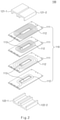
- FIG. 2 is a diagram illustrating a configuration of a transformer.
- a transformer 100 may include a multilayer circuit board 110, a first upper core 121-1, a second upper core 121-2, a first lower core 122-1, and a second lower core 122-2.
- the multilayer circuit board 110 may include a plurality of printed circuit boards 111.
- Each of the plurality of printed circuit boards 111 may have a winding 112 with a preset pattern.
- the printed circuit board 111 may be formed of an isolator such as an epoxy.
- the winding 112 may have a preset pattern formed on one surface of the printed circuit board 111, and may form a magnetic path that generates an electromagnetic induction.
- the winding 112 may be implemented with a metal foil such as a copper foil, a silver foil, or an aluminum foil made of a conductive material, or a conductive paste such as ink in which metal oxides are dispersed, to form the magnetic path.
- a metal foil such as a copper foil, a silver foil, or an aluminum foil made of a conductive material, or a conductive paste such as ink in which metal oxides are dispersed, to form the magnetic path.
- the winding 112 may be formed on each printed circuit board 111 in a spiral pattern centered on a central opening 113.
- the winding 112 formed on each printed circuit board 111 may have a different number of turns.
- the central opening 113 through which one leg of each of the first and second lower cores 122-1 and 122-2 may pass may be formed in each printed circuit board 111.
- the first and second upper cores 121-1 and 121-2 and the first and second lower cores 122-1 and 122-2 may be coupled in a form surrounding an outside centering on the central opening 113 of the multilayer circuit board 110.
- Each of the first and second upper cores 121-1 and 121-2 and the first and second lower cores 122-1 and 122-2 may be implemented as a magnetic material having magnetic properties.
- a transformation ratio may be determined based on the number of turns of the winding 112 formed on each printed circuit board 111.
- FIG. 3 is a diagram illustrating first and second planer transformers 130 and 140 included in a transformer illustrated in FIG. 2 .
- the first planar transformer 130 may include the first upper core 121-1, the first lower core 122-1, and the winding 112 between legs of the first lower core 122-1.
- the second planar transformer 140 may include the second upper core 121-2, the second lower core 122-2, and the winding 122 between legs of the second lower core 122-2.
- FIG. 4 is a circuit diagram illustrating a converter in some forms of the present disclosure.
- a converter may include an input device 10, the transformer 100, and an output device 20.
- the input device 10 may transfer a high voltage as an input voltage VS to the transformer 100.
- the input device 10 may include a switching device 11 and an input regulator 12.
- the switching device 11 may include a first switch Qp1 and a second switch Qp2.
- the first and second switches Qp1 and Qp2 may be alternately turned on.
- a current path of the input device 10 may be determined by the first and second switches Qp1 and Qp2 that are alternately turned on.
- a current may be provided to the transformer 100 through a first current path
- a current may be provided to the transformer 100 through a second current path
- the input regulator 12 may include a first capacitor CR, a first inductor LR, a second inductor Lm1, and a third inductor Lm2, and may remove noise from the current provided to the transformer 100.
- the transformer 100 may reduce the high voltage transferred from the input device 10 and may transfer the reduced voltage to the output device 20.
- the transformer 100 may include the first planar transformer 130 and the second planar transformer 140.
- first and second planar transformers 130 and 140 When the first and second planar transformers 130 and 140 are represented in a circuit diagram, they may be illustrated as primary winding coils Np1 and Np2 and secondary winding coils Ns1 and Ns2.
- the first planar transformer 130 may be illustrated as the primary winding coil Np1 and the secondary winding coil Ns1.
- Both ends of the primary winding coil Np1 of the first planar transformer 130 may be connected to both ends of the second inductor Lm1, respectively.
- the second planar transformer 140 may be illustrated as the primary winding coil Np2 and the secondary winding coil Ns2.
- Both ends of the primary winding coil Np2 of the second planar transformer 140 may be connected to both ends of the third inductor Lm2, respectively.
- the output device 20 may transfer a voltage (the low voltage) transformed by the transformer 100 to the external circuit (the electrical equipment).
- the output device 20 may include a rectifier 21 and a filter 22.
- the rectifier 21 may include a first diode Ds1 and a second diode Ds2, and may convert a voltage provided from the transformer 100 into the DC voltage
- the first and second diodes Ds1 and Ds2 included in the rectifier 21 may generate the DC voltage by flowing the current generated by the induced electromotive force that are generated in the secondary winding coils Ns1 and Ns2 of the first and second planar transformers 130 and 140 in one direction.
- the filter 22 may include a second capacitor Co and a resistor Ro, and may output an output voltage Vo by removing noise of the DC voltage provided from the rectifier 21.
- a current may flow through the primary winding coil Np1 of the first planar transformer 130.
- the induced electromotive force that is generated in the secondary winding coil Ns2 of the second planar transformer 140 may generate a current that flows through the first diode Ds1, the second capacitor Co, and the resistor Ro.
- the voltage Vo may be output from both ends of the resistor Ro through which the current flows.
- a current may flow through the primary winding coil Np2 of the second planar transformer 140.
- the induced electromotive force that is generated in the secondary winding coil Ns1 of the first planar transformer 130 may generate a current that flows through the second diode Ds2, the second capacitor Co, and the resistor Ro.
- the voltage Vo may be output from both ends of the resistor Ro through which the current flows.
- the first and second switches Qp1 and Qp2 are alternately turned on and the current path direction of the input device 10 is changed, as the current flows in only one direction from a top to a bottom of the resistor Ro in the output device 20, the DC voltage may be outputted at both ends of the resistor Ro.
- the high voltage input from the input device 10 may be reduced to the low voltage depending on the turns ratio of the primary winding coils Np1 and Np2 and the secondary winding coils Ns1 and Ns2 of each of the first and second planar transformers 130 and 140 and may be transferred to the external circuit (the electrical equipment) through the output device 20.
- a converter according to an embodiment of the present disclosure may reduce the DC voltage having the high voltage to the DC voltage having the low voltage and may output the reduced DC voltage.
- An output device that outputs the reduced voltage of a general converter includes an inductor for removing noise from the output voltage. Since a larger amount of current flows through the output as the rate at which the voltage is reduced, the inductor capable of withstanding the high current should be used. The inductor capable of withstanding the high current may be large in size and may increase component cost.
- the inductor is not required in the output device 20.
- a converter according to an embodiment of the present disclosure may reduce the size of the converter and may decrease the component cost, compared to the general converter.
- An embodiment of the present disclosure may improve power conversion efficiency and power conversion stability, and may reduce component cost.
- An embodiment of the present disclosure may improve fuel efficiency of a vehicle by increasing the power conversion efficiency.
- An embodiment of the present disclosure may improve the stability of a vehicle electric system by increasing the power conversion stability.
Landscapes
- Engineering & Computer Science (AREA)
- Power Engineering (AREA)
- Microelectronics & Electronic Packaging (AREA)
- Dc-Dc Converters (AREA)
- Coils Of Transformers For General Uses (AREA)
Abstract
A converter using a planar includes an input device that receives a first voltage, a transformer including a first planar transformer and a second planar transformer that reduce the first voltage, and an output device that outputs the first voltage as a second voltage, wherein the first voltage is greater than the second voltage, and the input device provides a current to a primary winding coil of each of the first planar transformer and the second planar transformer through a first current path and a second current path in which current directions are different with each other, and includes a plurality of inductors connected in parallel with the primary winding coil of each of the first planar transformer and the second planar transformer.
Description
- The present disclosure relates to a DC-DC converter using a planar transformer.
- In recent years, in response to the crisis of air pollution and oil depletion, technologies related to eco-friendly vehicles that use electric energy as vehicle power have been actively developed. The eco-friendly vehicles include hybrid electric vehicles, fuel cell electric vehicles, and electric vehicles.
- The eco-friendly vehicles include a high voltage battery for driving a vehicle and a low voltage battery for driving electrical equipment. The electric energy charged in the high voltage battery is used as a power source for the vehicle, and the electric energy charged in the low voltage battery is used as the power source for the electrical equipment in the vehicle.
- Since the rate of using the electric energy in general vehicles as well as eco-friendly vehicles is increasing, a development of a converter that stably supplies the electric energy and has good power conversion efficiency may be desired.
- An aspect of the present disclosure provides a converter using a planar transformer.
- The technical problems to be solved by the present inventive concept are not limited to the aforementioned problems, and any other technical problems not mentioned herein will be clearly understood from the following description by those skilled in the art to which the present disclosure pertains.
- According to an aspect of the present disclosure, a converter using a planar transformer includes an input device that receives a high voltage, a transformer including a first planar transformer and a second planar transformer that reduce a voltage provided from the input device, and an output device that outputs a voltage that is reduced by the transformer as a low voltage, and the input device provides a current to a primary winding coil of each of the first planar transformer and the second planar transformer through a first current path and a second current path in which current directions are different with each other, and includes a plurality of inductors connected in parallel with the primary winding coil of each of the first planar transformer and the second planar transformer.
- In order that the disclosure may be well understood, there will now be described various forms thereof, given by way of example, reference being made to the accompanying drawings, in which:
-
FIG. 1 is a diagram illustrating an actual configuration of a converter in one form of the present disclosure; -
FIGS. 2 and3 are diagrams illustrating a configuration of a planar transformer; -
FIG. 4 is a circuit diagram illustrating a converter in one form of the present disclosure; and -
FIG. 5 is a diagram describing an operation of a converter in one form of the present disclosure. - Hereinafter, some embodiments of the present disclosure will be described in detail through exemplary drawings. In adding reference numerals to elements of each drawing, it should be noted that the same elements are assigned the same numerals as possible even if they are indicated on different drawings. In addition, in describing an embodiment of the present disclosure, if it is determined that a detailed description of a related known configuration or function obstructs an understanding of the embodiment of the present disclosure, a detailed description thereof will be omitted.
- In describing the elements of the embodiments of the present disclosure, terms such as first, second, A, B, (a), (b), etc. may be used. These terms are only for distinguishing the element from other elements, and the nature, order, or order of the element is not limited by the term. In addition, unless otherwise defined, all terms used herein, including technical or scientific terms, have the same meaning as commonly understood by one of ordinary skill in the art to which the present disclosure belongs. Terms such as those defined in a commonly used dictionary should be interpreted as having a meaning consistent with the meaning in the context of the related technology, and should not be interpreted as an ideal or excessively formal meaning unless explicitly defined in this application.
- Hereinafter, embodiments of the present disclosure will be described in detail with reference to
FIGS. 1 to 3 . -
FIG. 1 is a diagram illustrating an actual configuration of a converter in some forms of the present disclosure. - Referring to
FIG. 1 , a converter according to an embodiment of the present disclosure may be implemented inside a vehicle. In this case, a converter may be integrally formed with the internal control units of the vehicle, and may be implemented as a separate device and may be connected to control units of the vehicle by separate connection means. - Referring to
FIG. 1 , a converter according to an embodiment of the present disclosure may include a circuit board, an input device, a transformer, and an output device. - The input device, the transformer, and the output device may be mounted on the circuit board.
- The input device may receive a high voltage and may transfer the received high voltage to the transformer. In this case, the input device may reduce and transfer a noise component included in the high voltage when the high voltage is transferred to the transformer.
- The transformer may convert the high voltage to a low voltage by lowering the voltage level of the high voltage transferred from the input device.
- The transformer may include a first planar transformer and a second planar transformer, and the first planar transformer and the second planar transformer may convert the high voltage to the low voltage by lowering the voltage level of the high voltage.
- The output device may transfer a low voltage of which voltage level is lowered through the transformer to an external circuit (electrical equipment). In this case, the output device may reduce a noise component included in the low voltage provided from the transformer and may output the low voltage with the reduced noise.
- In this case, both the high voltage input to the input device and the low voltage output from the output device may be a direct current (DC) voltage.
-
FIG. 2 is a diagram illustrating a configuration of a transformer. - A
transformer 100 may include amultilayer circuit board 110, a first upper core 121-1, a second upper core 121-2, a first lower core 122-1, and a second lower core 122-2. - The
multilayer circuit board 110 may include a plurality ofprinted circuit boards 111. - Each of the plurality of
printed circuit boards 111 may have a winding 112 with a preset pattern. - The printed
circuit board 111 may be formed of an isolator such as an epoxy. - The winding 112 may have a preset pattern formed on one surface of the printed
circuit board 111, and may form a magnetic path that generates an electromagnetic induction. - In this case, the winding 112 may be implemented with a metal foil such as a copper foil, a silver foil, or an aluminum foil made of a conductive material, or a conductive paste such as ink in which metal oxides are dispersed, to form the magnetic path.
- The winding 112 may be formed on each printed
circuit board 111 in a spiral pattern centered on acentral opening 113. - The
winding 112 formed on each printedcircuit board 111 may have a different number of turns. - The central opening 113 through which one leg of each of the first and second lower cores 122-1 and 122-2 may pass may be formed in each printed
circuit board 111. - The first and second upper cores 121-1 and 121-2 and the first and second lower cores 122-1 and 122-2 may be coupled in a form surrounding an outside centering on the
central opening 113 of themultilayer circuit board 110. - Each of the first and second upper cores 121-1 and 121-2 and the first and second lower cores 122-1 and 122-2 may be implemented as a magnetic material having magnetic properties.
- In the
transformer 100 configured as described above, a transformation ratio may be determined based on the number of turns of thewinding 112 formed on each printedcircuit board 111. -
FIG. 3 is a diagram illustrating first andsecond planer transformers FIG. 2 . - The first
planar transformer 130 may include the first upper core 121-1, the first lower core 122-1, and the winding 112 between legs of the first lower core 122-1. - The second
planar transformer 140 may include the second upper core 121-2, the second lower core 122-2, and the winding 122 between legs of the second lower core 122-2. -
FIG. 4 is a circuit diagram illustrating a converter in some forms of the present disclosure. - Referring to
FIG. 4 , a converter according to the embodiment of the present disclosure may include aninput device 10, thetransformer 100, and anoutput device 20. - The
input device 10 may transfer a high voltage as an input voltage VS to thetransformer 100. - The
input device 10 may include aswitching device 11 and aninput regulator 12. - The
switching device 11 may include a first switch Qp1 and a second switch Qp2. - In this case, the first and second switches Qp1 and Qp2 may be alternately turned on. A current path of the
input device 10 may be determined by the first and second switches Qp1 and Qp2 that are alternately turned on. - For example, when the first switch Qp1 is turned on, a current may be provided to the
transformer 100 through a first current path, and when the second switch Qp2 is turned on, a current may be provided to thetransformer 100 through a second current path. - The
input regulator 12 may include a first capacitor CR, a first inductor LR, a second inductor Lm1, and a third inductor Lm2, and may remove noise from the current provided to thetransformer 100. - The
transformer 100 may reduce the high voltage transferred from theinput device 10 and may transfer the reduced voltage to theoutput device 20. - The
transformer 100 may include the firstplanar transformer 130 and the secondplanar transformer 140. - When the first and second
planar transformers - The first
planar transformer 130 may be illustrated as the primary winding coil Np1 and the secondary winding coil Ns1. - Both ends of the primary winding coil Np1 of the first
planar transformer 130 may be connected to both ends of the second inductor Lm1, respectively. - The second
planar transformer 140 may be illustrated as the primary winding coil Np2 and the secondary winding coil Ns2. - Both ends of the primary winding coil Np2 of the second
planar transformer 140 may be connected to both ends of the third inductor Lm2, respectively. - The
output device 20 may transfer a voltage (the low voltage) transformed by thetransformer 100 to the external circuit (the electrical equipment). - The
output device 20 may include arectifier 21 and afilter 22. - The
rectifier 21 may include a first diode Ds1 and a second diode Ds2, and may convert a voltage provided from thetransformer 100 into the DC voltage - In more detail, the first and second diodes Ds1 and Ds2 included in the
rectifier 21 may generate the DC voltage by flowing the current generated by the induced electromotive force that are generated in the secondary winding coils Ns1 and Ns2 of the first and secondplanar transformers - The
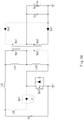
filter 22 may include a second capacitor Co and a resistor Ro, and may output an output voltage Vo by removing noise of the DC voltage provided from therectifier 21. - The operation of the converter according to the embodiment of the present disclosure configured as described above will be described with reference to
FIG. 5 as follows. - In the case of A) in
FIG. 5 , when the second switch Qp2 is turned on, the current path sequentially passing through the first inductor LR, the second inductor Lm1, the third inductor Lm2, and the second switch Qp2 may be formed. - In this case, a current may flow through the primary winding coil Np1 of the first
planar transformer 130. - When the current flows through the primary winding coil Np1 of the first
planar transformer 130, a magnetic flux is generated, and the induced electromotive force may be generated in the secondary winding coil Ns2 of the secondplanar transformer 140. - The induced electromotive force that is generated in the secondary winding coil Ns2 of the second
planar transformer 140 may generate a current that flows through the first diode Ds1, the second capacitor Co, and the resistor Ro. - In this case, the voltage Vo may be output from both ends of the resistor Ro through which the current flows.
- Meanwhile, in the case of B) in
FIG. 5 , when the first switch Qp1 is turned on, a current path sequentially passing through the third inductor Lm2, the second inductor Lm1, the first inductor LR, the first capacitor CR, and the first switch Qp1 may be formed. - In this case, a current may flow through the primary winding coil Np2 of the second
planar transformer 140. - When the current flows through the primary winding coil Np2 of the second
planar transformer 140, a magnetic flux is generated, and the induced electromotive force may be generated in the secondary winding coil Ns1 of the firstplanar transformer 130. - The induced electromotive force that is generated in the secondary winding coil Ns1 of the first
planar transformer 130 may generate a current that flows through the second diode Ds2, the second capacitor Co, and the resistor Ro. - In this case, the voltage Vo may be output from both ends of the resistor Ro through which the current flows.
- Even though the first and second switches Qp1 and Qp2 are alternately turned on and the current path direction of the
input device 10 is changed, as the current flows in only one direction from a top to a bottom of the resistor Ro in theoutput device 20, the DC voltage may be outputted at both ends of the resistor Ro. - In addition, the high voltage input from the
input device 10 may be reduced to the low voltage depending on the turns ratio of the primary winding coils Np1 and Np2 and the secondary winding coils Ns1 and Ns2 of each of the first and secondplanar transformers output device 20. - That is, a converter according to an embodiment of the present disclosure may reduce the DC voltage having the high voltage to the DC voltage having the low voltage and may output the reduced DC voltage.
- Referring to A) and B) in
FIG. 5 , in a converter according to an embodiment of the present disclosure, even though the first and second switches Qp1 and Qp2 are alternately turned on and the current path direction of theinput device 10 is changed, the current passes through all of the first to third inductors LR, Lm1, and Lm2, thereby removing noise from the current flowing through the primary winding coils Np1 and Np2 of the first and secondplanar transformers - Therefore, since the current provided from the
input device 10 to thetransformer 100 is provided with noise removed, an occurrence of noise components may be blocked in the induced electromotive force that is generated from the secondary winding coils Ns1 and Ns2 of the first and secondplanar transformers - An output device that outputs the reduced voltage of a general converter includes an inductor for removing noise from the output voltage. Since a larger amount of current flows through the output as the rate at which the voltage is reduced, the inductor capable of withstanding the high current should be used. The inductor capable of withstanding the high current may be large in size and may increase component cost.
- In contrast, unlike the general converter, when a voltage or a current is provided from the input device receiving the high voltage to the transformer, as the converter according to an embodiment of the present disclosure removes noise and transfers the voltage or the current, the inductor is not required in the
output device 20. - Accordingly, a converter according to an embodiment of the present disclosure may reduce the size of the converter and may decrease the component cost, compared to the general converter.
- An embodiment of the present disclosure may improve power conversion efficiency and power conversion stability, and may reduce component cost.
- An embodiment of the present disclosure may improve fuel efficiency of a vehicle by increasing the power conversion efficiency.
- An embodiment of the present disclosure may improve the stability of a vehicle electric system by increasing the power conversion stability.
- In addition to this, various effects that are directly or indirectly identified through this document may be provided.
- The above description is only illustrative of the technical idea of the present disclosure, and those of ordinary skill in the art to which the present disclosure pertains will be able to make various modifications and variations without departing from the essential characteristics of the present disclosure.
- Accordingly, the embodiments disclosed in the present disclosure are not intended to limit the technical idea of the present disclosure, but to explain the technical idea, and the scope of the technical idea of the present disclosure is not limited by these embodiments. The scope of protection of the present disclosure should be interpreted by the following claims, and all technical ideas within the scope equivalent thereto should be construed as being included in the scope of the present disclosure.
Claims (9)
- A converter using a planar transformer comprising:an input device configured to receive a first voltage;a transformer including a first planar transformer and a second planar transformer, the transformer configured to reduce the first voltage; andan output device configured to output the first voltage as a second voltage, wherein the first voltage is greater than the second voltage,wherein the input device is configured to provide a current to a primary winding coil of each of the first planar transformer and the second planar transformer through a first current path and a second current path in which current directions are different with each other, andwherein the input device includes a plurality of inductors connected in parallel with the primary winding coil of each of the first planar transformer and the second planar transformer.
- The converter of claim 1, wherein the input device includes:a switching device including a first switch and a second switch, the switching device configured to select one of the first current path or the second current path; andan input regulator configured to remove noise of the current provided to the primary winding coil of each of the first planar transformer and the second planar transformer through the selected first current path or the selected second current path.
- The converter of claim 2, wherein the input device is configured to:
provide the current to the primary winding coil of the first planar transformer through the first current path when the second switch is turned on. - The converter of claim 2 or 3, wherein the input regulator includes a first capacitor, a first inductor, a second inductor, and a third inductor,
wherein the first current path is a current path that sequentially passes through the first inductor, the second inductor, the third inductor, and the second switch, and
wherein the primary winding coil of the first planar transformer is connected in parallel with the second inductor. - The converter of any one of claims 2 to 4, wherein the input device is configured to:
provide the current to the primary winding coil of the second planar transformer through the second current path when the first switch is turned on. - The converter of any one of claims 2 to 5, wherein the input regulator includes a first capacitor, a first inductor, a second inductor, and a third inductor,
wherein the second current path is a current path that sequentially passes through the third inductor, the second inductor, the first inductor, the first capacitor, and the first switch, and
wherein the primary winding coil of the second planar transformer is connected in parallel with the third inductor. - The converter of any one of the preceding claims, wherein the plurality of inductors includes a first inductor and a second inductor,
wherein the primary winding coil of the first planar transformer is connected in parallel with the first inductor,
wherein the primary winding coil of the second planar transformer is connected in parallel with the second inductor,
wherein a secondary winding coil of each of the first planar transformer and the second planar transformer is electrically connected to the output device, and
wherein all currents generated by the first current path and the second current path flow through the first inductor and the second inductor. - The converter of any one of the preceding claims, wherein the first planar transformer and the second planar transformer include a multilayer circuit board, and an upper core and a lower core that are coupled in a form surrounding the multilayer circuit board,
wherein the multilayer circuit board includes a plurality of printed circuit boards,
wherein each of the plurality of printed circuit boards includes a winding formed in a spiral pattern, and
wherein the upper core and the lower core include a magnetic material. - The converrter of any one of the preceding claims, wherein the output device includes:a rectifier configured to allow a current provided from the secondary winding coils of the first planar transformer and the second planar transformer to flow in one direction; anda filter configured to remove noise from the current flowing through the rectifier.
Applications Claiming Priority (1)
| Application Number | Priority Date | Filing Date | Title |
|---|---|---|---|
| KR1020200086377A KR102829554B1 (en) | 2020-07-13 | 2020-07-13 | Converter using planar transformer |
Publications (1)
| Publication Number | Publication Date |
|---|---|
| EP3940935A1 true EP3940935A1 (en) | 2022-01-19 |
Family
ID=73059711
Family Applications (1)
| Application Number | Title | Priority Date | Filing Date |
|---|---|---|---|
| EP20205656.0A Pending EP3940935A1 (en) | 2020-07-13 | 2020-11-04 | Converter using planar transformer |
Country Status (5)
| Country | Link |
|---|---|
| US (1) | US11728735B2 (en) |
| EP (1) | EP3940935A1 (en) |
| JP (1) | JP2022017154A (en) |
| KR (1) | KR102829554B1 (en) |
| CN (1) | CN113938015A (en) |
Families Citing this family (1)
| Publication number | Priority date | Publication date | Assignee | Title |
|---|---|---|---|---|
| KR20240127258A (en) * | 2023-02-15 | 2024-08-22 | 엘지이노텍 주식회사 | Power Converting Apparatus |
Citations (1)
| Publication number | Priority date | Publication date | Assignee | Title |
|---|---|---|---|---|
| GB2517015A (en) * | 2013-08-08 | 2015-02-11 | Megger Instr Ltd | Transformer |
Family Cites Families (9)
| Publication number | Priority date | Publication date | Assignee | Title |
|---|---|---|---|---|
| US5684678A (en) * | 1995-12-08 | 1997-11-04 | Delco Electronics Corp. | Resonant converter with controlled inductor |
| US7289329B2 (en) * | 2004-06-04 | 2007-10-30 | Siemens Vdo Automotive Corporation | Integration of planar transformer and/or planar inductor with power switches in power converter |
| US7460002B2 (en) * | 2005-06-09 | 2008-12-02 | Alexander Estrov | Terminal system for planar magnetics assembly |
| JP5157987B2 (en) * | 2009-03-25 | 2013-03-06 | 株式会社豊田自動織機 | Isolated DC-DC converter |
| JP5788012B2 (en) * | 2011-09-28 | 2015-09-30 | 三菱電機株式会社 | Light source lighting device |
| JP6364988B2 (en) * | 2014-06-18 | 2018-08-01 | 富士通株式会社 | Planar type transformer |
| KR101988089B1 (en) | 2016-11-04 | 2019-06-12 | 현대자동차주식회사 | Circuit having variable output and controller comprising the same |
| JP6624160B2 (en) * | 2017-05-23 | 2019-12-25 | オムロン株式会社 | Transformer integrated printed circuit board |
| KR102009351B1 (en) * | 2017-12-18 | 2019-08-12 | 순천향대학교 산학협력단 | High Efficiency LLC Resonant Converter with Balanced Secondary Currents using the Two Transformer Structure |
-
2020
- 2020-07-13 KR KR1020200086377A patent/KR102829554B1/en active Active
- 2020-10-30 US US17/085,658 patent/US11728735B2/en active Active
- 2020-11-04 EP EP20205656.0A patent/EP3940935A1/en active Pending
- 2020-11-23 CN CN202011323022.3A patent/CN113938015A/en active Pending
- 2020-11-27 JP JP2020197303A patent/JP2022017154A/en active Pending
Patent Citations (1)
| Publication number | Priority date | Publication date | Assignee | Title |
|---|---|---|---|---|
| GB2517015A (en) * | 2013-08-08 | 2015-02-11 | Megger Instr Ltd | Transformer |
Non-Patent Citations (4)
| Title |
|---|
| "Power electronics handbook : devices, circuits, and applications", 1 January 2011, ELSEVIER/BH, BUTTERWORTH-HEINEMANN, Amsterdam [u.a.], ISBN: 978-0-12-382036-5, article LUO FANG LIN ET AL: "DC/DC Conversion Technique and Twelve Series Luo-converters", pages: 265 - 356, XP093014091, DOI: 10.1016/B978-0-12-382036-5.00014-8 * |
| LEE: "Active-Clamp Forward Converter With Asymmetric Transformer Turns For Reducing Transformer DC Offset Current Byoung-Hee Lee, Young-Do Kim, Moon-Young Kim, In-Ho Cho and Gun-Woo Moon", 30 December 2012 (2012-12-30), XP093014039, Retrieved from the Internet <URL:https://ieeexplore.ieee.org/stampPDF/getPDF.jsp?tp=&arnumber=6388807&ref=> [retrieved on 20230113] * |
| LIU YU-CHEN ET AL: "Design and Implementation of a High Power Density Active-Clamped Flyback Converter", 2018 INTERNATIONAL POWER ELECTRONICS CONFERENCE (IPEC-NIIGATA 2018 -ECCE ASIA), IEEJ INDUSTRY APPLICATION SOCIETY, 20 May 2018 (2018-05-20), pages 2092 - 2096, XP033426542, DOI: 10.23919/IPEC.2018.8507824 * |
| VIJAYA KUMAR N ET AL: "Analysis and design methodology for Planar Transformer with low self-capacitance used in high voltage flyback charging circuit", 2016 IEEE INTERNATIONAL CONFERENCE ON POWER ELECTRONICS, DRIVES AND ENERGY SYSTEMS (PEDES), IEEE, 14 December 2016 (2016-12-14), pages 1 - 5, XP033090121, DOI: 10.1109/PEDES.2016.7914510 * |
Also Published As
| Publication number | Publication date |
|---|---|
| CN113938015A (en) | 2022-01-14 |
| KR102829554B1 (en) | 2025-07-04 |
| US11728735B2 (en) | 2023-08-15 |
| KR20220008142A (en) | 2022-01-20 |
| JP2022017154A (en) | 2022-01-25 |
| US20220014103A1 (en) | 2022-01-13 |
Similar Documents
| Publication | Publication Date | Title |
|---|---|---|
| US12125631B2 (en) | Shielded electrical transformer | |
| Ouyang et al. | Analysis and design of fully integrated planar magnetics for primary–parallel isolated boost converter | |
| US11270832B2 (en) | Integrated magnetic device and direct current-direct current converter | |
| US20170011830A1 (en) | Magnetic assembly and power suppy system with same | |
| US11948722B2 (en) | Planar winding transformer | |
| CN107005166A (en) | Insulated type buck converter | |
| Gong et al. | Design and implementation of a 40-kV, 20-kJ/s capacitor charger for pulsed-power application | |
| CN113168956B (en) | Low-height coupled inductor | |
| EP4066267B1 (en) | Electrical power converter with segmented windings | |
| US9490057B2 (en) | Integrated magnetic module | |
| US11728735B2 (en) | Converter using planar transformer | |
| US20230207188A1 (en) | Differential transformer based voltage converter and method thereof | |
| Lim et al. | Low-profile contactless battery charger using planar printed circuit board windings as energy transfer device | |
| Bornwasser | Series-resonant-converter with galvanic isolation and> 99% efficiency | |
| US11855550B2 (en) | Power supply module | |
| JP3100526B2 (en) | Switching power supply | |
| US10404178B2 (en) | Insulation type step-up converter | |
| US20250233516A1 (en) | Dc-dc resonant power converter | |
| KR20130011962A (en) | Apparatus for controlling surge voltage | |
| US20250299874A1 (en) | High power high current transformer | |
| US20250087410A1 (en) | Matrix integrated transformer with built-in leakage inductance | |
| US20250273384A1 (en) | Planar transformer assembly and power adapter | |
| US20260004967A1 (en) | Integrated electronic component and resonant converter circuit | |
| JP5496005B2 (en) | Switching power supply | |
| Kim et al. | Design of On-board Power Supply for Tether Drone Applications |
Legal Events
| Date | Code | Title | Description |
|---|---|---|---|
| PUAI | Public reference made under article 153(3) epc to a published international application that has entered the european phase |
Free format text: ORIGINAL CODE: 0009012 |
|
| STAA | Information on the status of an ep patent application or granted ep patent |
Free format text: STATUS: REQUEST FOR EXAMINATION WAS MADE |
|
| 17P | Request for examination filed |
Effective date: 20210602 |
|
| AK | Designated contracting states |
Kind code of ref document: A1 Designated state(s): AL AT BE BG CH CY CZ DE DK EE ES FI FR GB GR HR HU IE IS IT LI LT LU LV MC MK MT NL NO PL PT RO RS SE SI SK SM TR |
|
| STAA | Information on the status of an ep patent application or granted ep patent |
Free format text: STATUS: EXAMINATION IS IN PROGRESS |
|
| 17Q | First examination report despatched |
Effective date: 20230124 |
|
| P01 | Opt-out of the competence of the unified patent court (upc) registered |
Effective date: 20230505 |