EP3940927A1 - Dispositif d'entraînement, en particulier pour un système de compresseur destiné à la génération de l'air comprimé dans un frein de véhicule - Google Patents
Dispositif d'entraînement, en particulier pour un système de compresseur destiné à la génération de l'air comprimé dans un frein de véhicule Download PDFInfo
- Publication number
- EP3940927A1 EP3940927A1 EP21185390.8A EP21185390A EP3940927A1 EP 3940927 A1 EP3940927 A1 EP 3940927A1 EP 21185390 A EP21185390 A EP 21185390A EP 3940927 A1 EP3940927 A1 EP 3940927A1
- Authority
- EP
- European Patent Office
- Prior art keywords
- electric motor
- housing
- contact elements
- line
- contact
- Prior art date
- Legal status (The legal status is an assumption and is not a legal conclusion. Google has not performed a legal analysis and makes no representation as to the accuracy of the status listed.)
- Pending
Links
Images


Classifications
-
- H—ELECTRICITY
- H02—GENERATION; CONVERSION OR DISTRIBUTION OF ELECTRIC POWER
- H02K—DYNAMO-ELECTRIC MACHINES
- H02K5/00—Casings; Enclosures; Supports
- H02K5/04—Casings or enclosures characterised by the shape, form or construction thereof
- H02K5/22—Auxiliary parts of casings not covered by groups H02K5/06-H02K5/20, e.g. shaped to form connection boxes or terminal boxes
- H02K5/225—Terminal boxes or connection arrangements
-
- H—ELECTRICITY
- H01—ELECTRIC ELEMENTS
- H01R—ELECTRICALLY-CONDUCTIVE CONNECTIONS; STRUCTURAL ASSOCIATIONS OF A PLURALITY OF MUTUALLY-INSULATED ELECTRICAL CONNECTING ELEMENTS; COUPLING DEVICES; CURRENT COLLECTORS
- H01R12/00—Structural associations of a plurality of mutually-insulated electrical connecting elements, specially adapted for printed circuits, e.g. printed circuit boards [PCB], flat or ribbon cables, or like generally planar structures, e.g. terminal strips, terminal blocks; Coupling devices specially adapted for printed circuits, flat or ribbon cables, or like generally planar structures; Terminals specially adapted for contact with, or insertion into, printed circuits, flat or ribbon cables, or like generally planar structures
- H01R12/70—Coupling devices
- H01R12/71—Coupling devices for rigid printing circuits or like structures
- H01R12/712—Coupling devices for rigid printing circuits or like structures co-operating with the surface of the printed circuit or with a coupling device exclusively provided on the surface of the printed circuit
- H01R12/716—Coupling device provided on the PCB
-
- H—ELECTRICITY
- H01—ELECTRIC ELEMENTS
- H01R—ELECTRICALLY-CONDUCTIVE CONNECTIONS; STRUCTURAL ASSOCIATIONS OF A PLURALITY OF MUTUALLY-INSULATED ELECTRICAL CONNECTING ELEMENTS; COUPLING DEVICES; CURRENT COLLECTORS
- H01R13/00—Details of coupling devices of the kinds covered by groups H01R12/70 or H01R24/00 - H01R33/00
- H01R13/02—Contact members
- H01R13/04—Pins or blades for co-operation with sockets
-
- H—ELECTRICITY
- H01—ELECTRIC ELEMENTS
- H01R—ELECTRICALLY-CONDUCTIVE CONNECTIONS; STRUCTURAL ASSOCIATIONS OF A PLURALITY OF MUTUALLY-INSULATED ELECTRICAL CONNECTING ELEMENTS; COUPLING DEVICES; CURRENT COLLECTORS
- H01R13/00—Details of coupling devices of the kinds covered by groups H01R12/70 or H01R24/00 - H01R33/00
- H01R13/46—Bases; Cases
- H01R13/52—Dustproof, splashproof, drip-proof, waterproof, or flameproof cases
- H01R13/5202—Sealing means between parts of housing or between housing part and a wall, e.g. sealing rings
-
- H—ELECTRICITY
- H01—ELECTRIC ELEMENTS
- H01R—ELECTRICALLY-CONDUCTIVE CONNECTIONS; STRUCTURAL ASSOCIATIONS OF A PLURALITY OF MUTUALLY-INSULATED ELECTRICAL CONNECTING ELEMENTS; COUPLING DEVICES; CURRENT COLLECTORS
- H01R13/00—Details of coupling devices of the kinds covered by groups H01R12/70 or H01R24/00 - H01R33/00
- H01R13/73—Means for mounting coupling parts to apparatus or structures, e.g. to a wall
- H01R13/74—Means for mounting coupling parts in openings of a panel
- H01R13/748—Means for mounting coupling parts in openings of a panel using one or more screws
-
- H—ELECTRICITY
- H01—ELECTRIC ELEMENTS
- H01R—ELECTRICALLY-CONDUCTIVE CONNECTIONS; STRUCTURAL ASSOCIATIONS OF A PLURALITY OF MUTUALLY-INSULATED ELECTRICAL CONNECTING ELEMENTS; COUPLING DEVICES; CURRENT COLLECTORS
- H01R2105/00—Three poles
-
- H—ELECTRICITY
- H01—ELECTRIC ELEMENTS
- H01R—ELECTRICALLY-CONDUCTIVE CONNECTIONS; STRUCTURAL ASSOCIATIONS OF A PLURALITY OF MUTUALLY-INSULATED ELECTRICAL CONNECTING ELEMENTS; COUPLING DEVICES; CURRENT COLLECTORS
- H01R2201/00—Connectors or connections adapted for particular applications
- H01R2201/10—Connectors or connections adapted for particular applications for dynamoelectric machines
-
- H—ELECTRICITY
- H01—ELECTRIC ELEMENTS
- H01R—ELECTRICALLY-CONDUCTIVE CONNECTIONS; STRUCTURAL ASSOCIATIONS OF A PLURALITY OF MUTUALLY-INSULATED ELECTRICAL CONNECTING ELEMENTS; COUPLING DEVICES; CURRENT COLLECTORS
- H01R4/00—Electrically-conductive connections between two or more conductive members in direct contact, i.e. touching one another; Means for effecting or maintaining such contact; Electrically-conductive connections having two or more spaced connecting locations for conductors and using contact members penetrating insulation
- H01R4/28—Clamped connections, spring connections
-
- H—ELECTRICITY
- H02—GENERATION; CONVERSION OR DISTRIBUTION OF ELECTRIC POWER
- H02K—DYNAMO-ELECTRIC MACHINES
- H02K11/00—Structural association of dynamo-electric machines with electric components or with devices for shielding, monitoring or protection
- H02K11/30—Structural association with control circuits or drive circuits
- H02K11/33—Drive circuits, e.g. power electronics
-
- H—ELECTRICITY
- H02—GENERATION; CONVERSION OR DISTRIBUTION OF ELECTRIC POWER
- H02K—DYNAMO-ELECTRIC MACHINES
- H02K2203/00—Specific aspects not provided for in the other groups of this subclass relating to the windings
- H02K2203/09—Machines characterised by wiring elements other than wires, e.g. bus rings, for connecting the winding terminations
-
- H—ELECTRICITY
- H02—GENERATION; CONVERSION OR DISTRIBUTION OF ELECTRIC POWER
- H02K—DYNAMO-ELECTRIC MACHINES
- H02K3/00—Details of windings
- H02K3/46—Fastening of windings on the stator or rotor structure
- H02K3/50—Fastening of winding heads, equalising connectors, or connections thereto
Definitions
- the invention relates to a drive device with an electric motor, which is arranged in an electric motor housing, and with a control unit, which is arranged in a control unit housing outside the electric motor housing, in particular directly on or directly on the electric motor housing.
- Electronic control devices are used to control electric motors, in particular with regard to speed and/or drive power.
- a drive device which is characterized in that a line element receiving component is arranged on the inside of the electric motor housing, which has a plurality of line channels, through which an electrical line element, in particular a winding wire of the electric motor, runs, with each of the line channels in each case an electrically conductive contact element protruding through an opening in the electric motor housing protrudes, which has at least two prongs at its free end, between which the respective electrical conducting element is clamped.
- the drive device has the very special advantage that it provides an electrical connection of the control unit to an electric motor, in particular a three-phase electric motor allows that is particularly safe and reliable and can still be produced by simply plugging and screwing. It is of particular advantage here that during the process of mechanically coupling the control device, the electrical coupling also takes place automatically in a safe and reliable manner at the same time. In this case, it can advantageously be provided in particular that the control unit housing is fastened to the electric motor housing during assembly of the drive device, in particular immovably and/or detachably again without destruction.
- the electrical line elements can in particular be winding wires of the electric motor.
- it can be winding wires that are wound up to form stator coils.
- additional separate lines for connecting the electric motor and thus also additional electrical connections can advantageously be dispensed with inside the electric motor housing.
- the winding wires themselves can be directly contacted via the contact elements from the outside, which reduces the manufacturing effort and is advantageous for reliability.
- the line elements are additional lines, in particular wires, which are electrically conductively connected to the winding wires of the electric motor, in particular the stator of the electric motor.
- the line elements in particular precisely three of the line elements, are winding wires of the electric motor or lines, in particular wires, which are electrically conductively connected to the winding wires of the electric motor, in particular the stator of the electric motor.
- several (additional) line elements in particular exactly two of the line elements, are signal lines.
- three of the line elements are winding wires of the electric motor, while two (more) of the line elements are signal lines that are used in particular to connect a sensor, in particular a temperature sensor.
- the contact elements are preferably fixed in a connector housing.
- the advantage of the plug housing is that the contact elements can be handled easily together, with the plug housing together with the contact elements fixed therein advantageously being able to be used and installed like a plug connector.
- the line element receiving component has a Has recording, in which a projection of the connector housing can be inserted positively and / or clamping and / or latching.
- the line element receiving component and/or the connector housing can be made of plastic in particular.
- the line element receiving component and the connector housing are each produced as a plastic injection molded part.
- the plug housing can be produced, for example, using a plastic injection molding process, in which the contact elements are overmoulded.
- the plug housing has at least one connecting element, in particular a latching element or at least one rivet, which interacts with a counter-connecting element of the line element receiving component in order to connect the plug housing and the line element receiving component to one another, in particular through the electric motor housing.
- the plug housing has at least one screw receptacle for a fastening screw, which runs through a bore in the electric motor housing and is screwed into the line element receiving component.
- the contact elements serve to create an electrically conductive connection between the control unit and the cables connected to the electric motor.
- supply voltages between 200 volts and 1,000 volts come into consideration.
- the electric motor can in particular be a synchronous motor and/or a permanent magnet motor.
- the contact elements can each have a plurality, in particular exactly two, pairs of prongs, between which the respective electrical line element is clamped. By providing multiple pairs of prongs, a particularly secure, durable, and reliable electrical connection is established.
- the electrical line elements can in particular be line elements that have an insulating sheathing.
- it can be enameled copper wire, for example.
- the prongs preferably each have a cutting edge, in particular directed towards the line element, or each one, in particular directed towards the line element, friction surface. This advantageously ensures that the insulating sheath is cut or rubbed off when attaching the contact element to the line element in the area of the prongs, so that a direct electrically conductive contact is made from the contact element to the electrically conductive core of the cable.
- the contact elements are preferably made of a metal or a metal alloy.
- the contact elements can advantageously have a coating, in particular a metallic coating.
- the coating can in particular be a galvanically applied coating, for example a galvanically applied nickel coating or the like. In this way, the contact elements are particularly well protected against external influences. In addition, a particularly low contact resistance can be achieved in this way.
- the contact elements can have a galvanically applied coating.
- the contact elements can advantageously be produced, for example, as stamped sheet metal parts and/or as sheet metal weighing parts.
- each contact element is produced in one piece from a single piece of raw material, in particular from sheet metal.
- a contact element can be produced, for example, as described below by stamping and bending: First, a stamped part is produced that is essentially H-shaped, with the two legs of the "H" being identical to one another. Each leg of the H has at least one prong, in particular several prongs, at the lower end. In a next step, each leg is bent twice just above the prongs. This can be done in particular by bending each leg by about 90 degrees at locations spaced apart from one another in the longitudinal direction, with bending taking place in opposite directions. Then the two legs of the "H” are placed one on top of the other, with the section connecting the legs (cross line of the H) being bent by 180°. As a result of the double bending, the prongs of the legs are at a distance from one another in the end result.
- a contact element preferably has at least two prongs at its free end, between which a signal line is clamped within the coupling element.
- exactly two such contact elements each have at least two prongs at their free end, between which a signal line is clamped.
- the signal lines can be connected, for example, to a sensor arranged in the electric motor housing, in particular to a temperature sensor.
- each contact element has at least one cutting edge at its other end.
- the cutting edge makes it easier to plug the other end into a circuit board connector, for example.
- other coupling variants such as a press fit or a soldered THT connection (Through Hole Technology), can also be considered, which can also do without a cutting edge.
- the ends of the signal lines are fixed in a plug that is plugged into a plug receptacle of the coupling element.
- a plug that can be plugged into a plug socket of the coupling element it is particularly easy to bring the additional line elements into the necessary position for coupling to the additional coupling elements and to hold them there.
- control device can be designed in such a way that all the essential electronic components are arranged on a single circuit board.
- circuit board is mounted by simply plugging it onto the counter-coupling element, after part of the control unit housing has already been mechanically connected to the electric motor housing, which is explained in detail further below.
- the other ends of the contact elements can each be plugged into a plug connector of the control unit.
- the plug connector can in particular be a printed circuit board plug connector which is fastened to a circuit board of the control unit which carries electronic components. In this way, additional lines, wires or cables within the control unit housing are advantageously avoided. In addition, as already mentioned above, a particularly quick, safe and simple assembly is made possible.
- the connector housing has a first contact surface that faces the outside of the electric motor housing.
- the connector housing can have a second contact surface, which faces the outside of the control unit housing.
- the first contact surface can have a first groove in which a first seal, in particular a sealing ring, is arranged.
- the contact surface can have a second groove in which a second seal, in particular a Sealing ring is arranged.
- the interior of the electric motor housing and the interior of the control unit housing are pressure-technically isolated from the outside environment by the seals, so that a pressure difference of several bars is possible.
- the control unit can contain an inverter to convert a DC voltage, for example a vehicle battery, into an AC voltage for operating the electric motor.
- the inverter can in particular be a three-phase inverter which is designed to convert a direct current into a three-phase alternating current.
- the drive device according to the invention can, in particular, be part of a compressor system for generating compressed air, which includes a pump, in particular a reciprocating piston pump.
- the drive device according to the invention can be used here to drive the pump in order to generate compressed air.
- the compressed air can be used in particular to operate a compressed air brake, in particular a motor vehicle brake.
- a braking system for a motor vehicle that contains a drive device according to the invention or the above-mentioned compressor system for generating compressed air is of particular advantage.
- the brake system can in particular be part of a motor vehicle, in particular a truck.
- the motor vehicle is designed as an electric vehicle, in particular as an electrically driven road vehicle.
- the motor vehicle can contain an inverter in order to convert the DC voltage of a vehicle battery into an AC voltage for operating the electric motor, in particular if the control unit of the drive device does not have its own inverter.
- the inverter can be a three-phase inverter.
- the drive device according to the invention or the above-mentioned compressor system or the above-mentioned braking system to have an inverter for converting direct current, for example from a vehicle battery, into alternating current for operating the electric motor.
- the electric motor it is also possible for the electric motor to be a DC motor, so that an inverter is not required in this case.
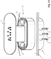
- figure 1 shows a first exemplary embodiment of a drive device according to the invention with an electric motor 1 which is arranged in an electric motor housing 2 .
- the drive device has a control unit 3 which contains electronic components (not shown) arranged on a circuit board 4 and which is arranged in a control unit housing 5 .
- the control unit housing 5 is attached to the electric motor housing 2 by means of attachment means 6 .
- a duct element receiving member 7 On the inside of the electric motor housing 2, there is arranged a duct element receiving member 7, which has a plurality of (in figure 1 not visible) line channels 8, through each of which an electrical line element 9 connected to the electric motor 1 runs and which each run through a line perpendicular to the respective line channel (in figure 1 not visible) access channel 18 run.
- an electrical contact element 11 Through each of the (in figure 1 (not visible) access channels 18 runs through an opening 10 of the electric motor housing 2 protruding electrical contact element 11, which is in electrically conductive contact at its free end with the electrical line element 9 assigned to it.
- the electrical line elements 9 can in particular be winding wires of the electric motor 1 , in particular of a stator of the electric motor 1 .
- a sensor 12 which can in particular be a temperature sensor which is connected by means of further electrical line elements 13 .
- further contact elements 14 which also protrude through the opening 10 of the electric motor housing 2 and each run through a (not shown) further access channel 40 of the coupling element 7 and within the Coupling element 7 are conductively connected to the ends of the other electrical line elements 13.
- the contact elements 11 and the further contact elements 14 are fixed in a connector housing 15 .
- the contact elements 11 and the further contact elements 14 are arranged parallel to one another with regard to their direction of longitudinal extension.
- circuit board 4 On the circuit board 4 are (in figure 1 not shown) printed circuit board connector 16 arranged, in which the contact elements 11 and the other contact elements 14 are inserted to produce a conductive connection.
- FIGS. 2 to 8 each show a detailed view of a second exemplary embodiment of a drive device according to the invention, the electric motor not being drawn in each case.
- the drive device has an electric motor housing 2 with an opening 10 .
- On the side next to the opening 10 are holes 17 for (in figure 2 not shown) fastening screws 41 available.
- On the inside of the electric motor housing 2 there is a line element receiving component 7 which has a plurality of line channels 8 (perpendicular to the plane of the drawing).
- An electrical line element 9 runs through each of the line channels 8, which is connected to the (in the Figures 2 to 8 not shown) electric motor 1 is connected and is used to supply the electric motor 1 with electrical energy.
- Each of the line ducts 8 runs through an access duct 18.
- the longitudinal extent of the respective cable tunnel 8 is aligned perpendicular to the course of the respective access tunnel 18.
- the access channels 18 each have an access tunnel opening 19 which is aligned with the opening 10 of the electric motor housing 2 .
- a plug housing 15, in which electrically conductive contact elements 11 are fixed is first coupled.
- Each of the contact elements 11 has at least two prongs 21 on its free end 20 .
- the tines 21 each have a friction surface 22, the friction surfaces 22 facing each other.
- the free ends 20 of the electrically conductive contact elements 11 have cable receptacles 23 for the electrical line elements 9 .
- the line element receiving component 7 has a receptacle 24 into which a projection 25 of the connector housing 15 can be inserted in a form-fitting manner and/or in a clamped and/or latching manner.
- the connector housing 15 has screw receptacles 26 for the fastening screws 41 .
- the projection 25 is inserted through the opening 10 into the receptacle 24 , as a result of which the free ends 20 of the electrically conducting contact elements 11 are automatically inserted into the access channels 18 .
- the friction surfaces 22 of the tines 21 remove the electrical insulation of the respective electrical line element 9 in a partial area, so that an electrically conductive contact is produced between the contact elements 11 and the electrical line elements 9 .
- the electrical conductors of the electrical line elements 9 are in the cable receptacles 23.
- the connector housing 15 has a first contact surface 27 which faces the outside of the electric motor housing 2 .
- the first contact surface 27 has a circumferential groove 28 for a (in figure 2 not shown) first sealing ring 38 on.
- the connector housing 15 also has a second contact surface 29 which, in the final installed state, is on the outside of the control unit housing 5, which is figure 2 is not shown, faces.
- the second contact surface 29 has a circumferential second groove 30 for a second sealing ring 39 .
- the other ends 32 of the electrically conductive contact elements 11 each have a cutting edge 33 and are designed to each be cut into a (in figure 2 not shown) PCB connector 16 to be inserted.
- FIG 3 shows the state after the connector housing 15 has been coupled to the line element receiving component 7.
- the connector housing 15 is fastened by means of fastening screws 41 which run through the bores 17 in the electric motor housing 2 and are screwed into screw-receiving recesses 34 in the coupling element 7.
- the fastening screws 41 can in particular be self-tapping fastening screws.
- the screw receptacles 26 are designed in such a way that the screw heads of the fastening screws 41 are countersunk relative to the second contact surface 41 .
- a control unit housing is attached to the electric motor housing 2 .
- the control housing 5 has a control housing opening 35 for the connector housing 15 and the coupling elements 11 .
- this shows Control unit housing 5 through-holes 42 for further fastening screws 36.
- further fastening screws 36 can be screwed into screw receptacles 37 of the electric motor housing 2, which in figure 5 is shown.
- figure 5 shows the situation after the control unit housing 5 has been attached to the electric motor housing 2.
- the interior of the electric motor housing 2 and the outside environment are pressure-technically isolated from one another by the first sealing ring 38, so that a pressure difference of several bars is possible.
- the interior of the control unit housing 5 is isolated from the outside environment in terms of pressure with regard to pressure fluctuations by means of the second sealing ring 39 .
- control unit 3 which has a circuit board 4 , is coupled up.
- the circuit board 4 carries electronic components (not shown) and also circuit board connectors 16 into which the other ends 32 of the contact elements 11 are inserted, resulting in figure 7 is shown.
- the control unit 3 is thus able to control the electric motor 1 (not shown).
- the control device 3 can, for example, control the drive power of the electric motor.
- control housing 5 is closed by means of a control housing cover 43, which figure 8 is shown.
- FIG 9 shows a detailed view of a third embodiment of a drive device according to the invention.
- the third exemplary embodiment has a duct element receiving component 7 through which a duct 8 runs.
- An electrical line element 9 is laid through the line channel 8, the electrical line element 9 running in a loop. This means that the end of the electric wire 9 is conductively connected to an intermediate portion of the electric wire 9 . This is particularly advantageous with regard to the safety of the drive device, in particular with regard to any vibrations that may occur. In addition, this improves the thermal and electrical connection.
- the line element receiving component 7 also has an access channel 18 which runs perpendicularly to the line channel 8 .
- An electrically conductive contact element 11 is arranged in the access channel 18 and has two pairs of prongs (ie a total of four prongs) at its end.
- the prongs 21 each point towards the electrical conduction element 9 aligned friction surface 22 (not visible in this figure), which serves to remove the electrical insulation of the electrical cable 9 in the area of the prongs 21 when the contact element 11 is inserted, so that an electrically conductive contact is produced.
- FIG 10 shows the line element receiving component 7 in a different cross-sectional plane.
- a further contact element 14 which protrudes into a further access channel 40 and which has two fork-shaped prongs 21 at its end, between which another electrical line element 13 is clamped in an electrically conductive manner within the coupling element 7 in such a way that an electrical connection between the further Line element receiving component 14 and the further electrical line element 13 is formed.
- the tines 21 of the additional coupling element 14 have cutting edges aligned towards the additional electrical line element 13, which cut through the insulation of the additional electrical cable 13 when the additional contact element 14 is inserted, in order to create an electrically conductive connection between the additional electrical cable 14 and the additional contact element 14 to manufacture.
- the further electrical line element 13 is fixed in a plug 36 which is plugged into a plug-in socket 37 of the coupling element 7 . A part of the further access channel 40 therefore runs in the plug 36.
- FIGS. 11 to 15 show detailed views of a fourth embodiment of a drive device according to the invention.
- figure 11 shows a line element receiving component 7, which has a plurality of parallel cable tunnels 8 for each one (not shown in this figure) electrical line element 9.
- the cable tunnels 8 run completely through the line element receiving component 7 so that the electrical line elements 9 can be laid in a loop, with the end of the electrical cable 9 being conductively connected to an intermediate section of the electrical cable.
- the line element receiving component 7 has a receptacle 24 into which a projection 25 of the plug housing 15 can be inserted in a form-fitting and/or clamping and/or latching manner.
- the line element receiving component 7 also has screw receiving recesses 34 for screwing in fastening screws 41 .
- the conduction element receiving component 7 and the connector housing 15 can each be made of plastic, for example, in particular each using a plastic injection molding process.
- Electrically conductive contact elements 11 are arranged in the connector housing 15 .
- two further electrically conductive contact elements 14 are arranged in the plug housing 15, but due to the perspective representation in figure 11 are not visible.
- the electrical contact elements 11 are arranged in a first common plane, lying next to one another and aligned parallel to one another.
- the two further electrical contact elements 14 are arranged in a plane parallel thereto (behind).
- the further electrical contact elements 14 are arranged parallel to one another and parallel to the electrical contact elements 11 .
- figure 12 shows one of the electrical contact elements 11.
- the electrical contact element has two pairs of tines 21 (ie a total of four tines 21).
- the tines 21 each have a friction surface 22, the friction surfaces 22 of a pair facing each other.
- the friction surfaces 22 serve to remove the electrical insulation of an electrical cable 9 in the area of the prongs 21 when it is plugged on.
- the contact element also has a cable receptacle 23 in which the electrically conductive core of the electrical cable 9 is arranged and clamped in the end position.
- the other end 32 of the contact element 11 has a cutting edge 33, which facilitates plugging into a connector, in particular into a circuit board connector 16.
- the contact element 11 is produced as a stamped sheet metal part and a bent sheet metal part.
- a stamped part is produced that is essentially H-shaped, with the two legs of the "H” being identical to one another. Each leg of the H has two of the prongs 21 at the lower end.
- a double bending takes place just above the tines. Then the two legs of the "H” are placed one on top of the other, with the section connecting the legs (cross line of the H) being bent by 180°. As a result of the double bend 31, the pairs of prongs 21 are ultimately at a distance from one another.
- the cutting edge 33 is formed at the other end, for example by grinding or milling.
- the contact element 11 can in particular have a galvanically applied coating. This protects the contact element from external influences, in particular from corrosion.
- figure 13 shows the line element receiving component 7 in a different perspective Representation, the electrical line elements 9 that run through the cable tunnel 8 are also shown.
- figure 13 the six identical access channels 18 for the contact elements 11 and two further access channels 40 for the further contact elements 14 can also be seen.
- the figure 13 the receptacle 24 for the projection 25 of the connector housing 15 and the screw receptacle recesses 34.
- FIG 14 shows schematic details of the final installation state in which the plug housing 15 is firmly mechanically connected to the line element receiving component 7 by means of the fastening screws 41 .
- the wall of the electric motor housing 2 is clamped between the line element receiving component 7 and the first contact surface 27 of the plug housing 15 .
- the circuit board 4 of the control unit 3 (not visible in this figure) which has circuit board connectors 16 which are plugged onto the other ends 32 of the contact elements 11 .
- the circuit board 4 is located in a control unit housing 5 (not shown in this figure).
Applications Claiming Priority (1)
| Application Number | Priority Date | Filing Date | Title |
|---|---|---|---|
| LU101924A LU101924B1 (de) | 2020-07-13 | 2020-07-13 | Antriebsvorrichtung, insbesondere für ein Verdichtersystem zur Drucklufterzeugung bei einer Fahrzeugbremse |
Publications (1)
| Publication Number | Publication Date |
|---|---|
| EP3940927A1 true EP3940927A1 (fr) | 2022-01-19 |
Family
ID=71899801
Family Applications (1)
| Application Number | Title | Priority Date | Filing Date |
|---|---|---|---|
| EP21185390.8A Pending EP3940927A1 (fr) | 2020-07-13 | 2021-07-13 | Dispositif d'entraînement, en particulier pour un système de compresseur destiné à la génération de l'air comprimé dans un frein de véhicule |
Country Status (2)
| Country | Link |
|---|---|
| EP (1) | EP3940927A1 (fr) |
| LU (1) | LU101924B1 (fr) |
Citations (5)
| Publication number | Priority date | Publication date | Assignee | Title |
|---|---|---|---|---|
| DE102011112821A1 (de) | 2011-09-12 | 2013-03-14 | Brose Fahrzeugteile GmbH & Co. Kommanditgesellschaft, Würzburg | Elektromotor, insbesondere Kühlerlüftermotor |
| DE112015001426T5 (de) * | 2014-03-26 | 2016-12-08 | Sanden Holdings Corporation | Elektrischer Verdichter |
| EP3182448A1 (fr) * | 2015-12-18 | 2017-06-21 | Karlsruher Institut für Technologie | Structure de liaison modulaire multifonctionnelle |
| US20180367008A1 (en) | 2017-06-15 | 2018-12-20 | Samsung Electronics Co., Ltd. | Motor |
| DE102018204991A1 (de) * | 2018-04-04 | 2019-10-10 | Robert Bosch Gmbh | Elektrische Antriebseinheit mit einem Polgehäuse und einem Elektronikgehäuse |
-
2020
- 2020-07-13 LU LU101924A patent/LU101924B1/de active IP Right Grant
-
2021
- 2021-07-13 EP EP21185390.8A patent/EP3940927A1/fr active Pending
Patent Citations (5)
| Publication number | Priority date | Publication date | Assignee | Title |
|---|---|---|---|---|
| DE102011112821A1 (de) | 2011-09-12 | 2013-03-14 | Brose Fahrzeugteile GmbH & Co. Kommanditgesellschaft, Würzburg | Elektromotor, insbesondere Kühlerlüftermotor |
| DE112015001426T5 (de) * | 2014-03-26 | 2016-12-08 | Sanden Holdings Corporation | Elektrischer Verdichter |
| EP3182448A1 (fr) * | 2015-12-18 | 2017-06-21 | Karlsruher Institut für Technologie | Structure de liaison modulaire multifonctionnelle |
| US20180367008A1 (en) | 2017-06-15 | 2018-12-20 | Samsung Electronics Co., Ltd. | Motor |
| DE102018204991A1 (de) * | 2018-04-04 | 2019-10-10 | Robert Bosch Gmbh | Elektrische Antriebseinheit mit einem Polgehäuse und einem Elektronikgehäuse |
Also Published As
| Publication number | Publication date |
|---|---|
| LU101924B1 (de) | 2022-01-13 |
Similar Documents
| Publication | Publication Date | Title |
|---|---|---|
| EP2320092B1 (fr) | Unité de pompage | |
| EP0882318B1 (fr) | Connecteur electrique multiple multipolaire et partie de douille associee | |
| DE102019111691B4 (de) | Anordnung zum Steckverbinden elektrischer Anschlüsse und Vorrichtung zum Antreiben eines Verdichters mit der Anordnung | |
| EP1811604A2 (fr) | Barette à bornes électriques | |
| EP2190105A2 (fr) | Convertisseur de fréquence pour contrôler un moteur électrique | |
| DE102017205970A1 (de) | Lösbare elektrische Verbindung einer Leistungselektronik mit einer E-Maschine | |
| DE102017100251B4 (de) | Anordnung mit einer Vorrichtung zum Aufnehmen und Abstützen von Stromschienen | |
| DE102012218847A1 (de) | Anschlusselement für eine Antriebsanordnung sowie eine Antriebsanordnung mit einem Anschlussteil | |
| WO2003001647A1 (fr) | Couvercle de carter conçu pour un moteur electrique, en particulier pour un moteur a courant continu a commutation electronique | |
| EP2626645B1 (fr) | Groupe motopompe doté d'une prise électrique | |
| EP3673567B1 (fr) | Dispositif de raccordement et moteur électrique | |
| WO2014102068A2 (fr) | Groupe motopompe | |
| DE102017215729A1 (de) | Verbindungsvorrichtung und Verfahren zum elektrischen Verbinden eines Elektromotors mit einer elektronischen Schalteinheit, elektronische Schalteinheit, Verbindungseinheit und Vorrichtungssystem mit zumindest einer Verbindungsvorrichtung | |
| EP2209962B2 (fr) | Entraînement de porte à construction modulaire | |
| EP3484023A1 (fr) | Connecteur enfichable hybride pour un système d'entraînement | |
| DE202007019214U1 (de) | Netzstecker | |
| EP1202403B1 (fr) | Transition de cable déconnectable | |
| LU101924B1 (de) | Antriebsvorrichtung, insbesondere für ein Verdichtersystem zur Drucklufterzeugung bei einer Fahrzeugbremse | |
| DE102013211968A1 (de) | Elektrische Maschine, insbesondere Elektromotor | |
| EP0140079B1 (fr) | Système d'installation avec prise intermédiaire | |
| EP2095469A1 (fr) | Dispositif de montage pour recevoir des modules électroniques | |
| DE102020118406A1 (de) | Antriebsvorrichtung, insbesondere für ein Verdichtersystem zur Drucklufterzeugung bei einer Fahrzeugbremse | |
| DE102014215058A1 (de) | Anschlussvorrichtung zum Anschließen elektrischer Leitungen und Verfahren zur Montage einer derartigen Anschlussvorrichtung | |
| EP2255603A1 (fr) | Dispositif pour recevoir un composant électrique/électronique et procédé de montage correspondant, et élément de recouvrement pour un tel dispositif | |
| DE102004027653B4 (de) | Elektromotor |
Legal Events
| Date | Code | Title | Description |
|---|---|---|---|
| PUAI | Public reference made under article 153(3) epc to a published international application that has entered the european phase |
Free format text: ORIGINAL CODE: 0009012 |
|
| STAA | Information on the status of an ep patent application or granted ep patent |
Free format text: STATUS: THE APPLICATION HAS BEEN PUBLISHED |
|
| AK | Designated contracting states |
Kind code of ref document: A1 Designated state(s): AL AT BE BG CH CY CZ DE DK EE ES FI FR GB GR HR HU IE IS IT LI LT LU LV MC MK MT NL NO PL PT RO RS SE SI SK SM TR |
|
| STAA | Information on the status of an ep patent application or granted ep patent |
Free format text: STATUS: REQUEST FOR EXAMINATION WAS MADE |
|
| 17P | Request for examination filed |
Effective date: 20220719 |
|
| RBV | Designated contracting states (corrected) |
Designated state(s): AL AT BE BG CH CY CZ DE DK EE ES FI FR GB GR HR HU IE IS IT LI LT LU LV MC MK MT NL NO PL PT RO RS SE SI SK SM TR |