EP3940861A1 - Battery pack having bmu component damage prevention structure - Google Patents
Battery pack having bmu component damage prevention structure Download PDFInfo
- Publication number
- EP3940861A1 EP3940861A1 EP20914606.7A EP20914606A EP3940861A1 EP 3940861 A1 EP3940861 A1 EP 3940861A1 EP 20914606 A EP20914606 A EP 20914606A EP 3940861 A1 EP3940861 A1 EP 3940861A1
- Authority
- EP
- European Patent Office
- Prior art keywords
- bmu
- partition
- battery pack
- mounting part
- battery
- Prior art date
- Legal status (The legal status is an assumption and is not a legal conclusion. Google has not performed a legal analysis and makes no representation as to the accuracy of the status listed.)
- Pending
Links
Images



Classifications
-
- H—ELECTRICITY
- H01—ELECTRIC ELEMENTS
- H01M—PROCESSES OR MEANS, e.g. BATTERIES, FOR THE DIRECT CONVERSION OF CHEMICAL ENERGY INTO ELECTRICAL ENERGY
- H01M10/00—Secondary cells; Manufacture thereof
- H01M10/42—Methods or arrangements for servicing or maintenance of secondary cells or secondary half-cells
- H01M10/425—Structural combination with electronic components, e.g. electronic circuits integrated to the outside of the casing
-
- H—ELECTRICITY
- H01—ELECTRIC ELEMENTS
- H01M—PROCESSES OR MEANS, e.g. BATTERIES, FOR THE DIRECT CONVERSION OF CHEMICAL ENERGY INTO ELECTRICAL ENERGY
- H01M10/00—Secondary cells; Manufacture thereof
- H01M10/42—Methods or arrangements for servicing or maintenance of secondary cells or secondary half-cells
- H01M10/4207—Methods or arrangements for servicing or maintenance of secondary cells or secondary half-cells for several batteries or cells simultaneously or sequentially
-
- H—ELECTRICITY
- H01—ELECTRIC ELEMENTS
- H01M—PROCESSES OR MEANS, e.g. BATTERIES, FOR THE DIRECT CONVERSION OF CHEMICAL ENERGY INTO ELECTRICAL ENERGY
- H01M10/00—Secondary cells; Manufacture thereof
- H01M10/42—Methods or arrangements for servicing or maintenance of secondary cells or secondary half-cells
- H01M10/425—Structural combination with electronic components, e.g. electronic circuits integrated to the outside of the casing
- H01M10/4257—Smart batteries, e.g. electronic circuits inside the housing of the cells or batteries
-
- H—ELECTRICITY
- H01—ELECTRIC ELEMENTS
- H01M—PROCESSES OR MEANS, e.g. BATTERIES, FOR THE DIRECT CONVERSION OF CHEMICAL ENERGY INTO ELECTRICAL ENERGY
- H01M50/00—Constructional details or processes of manufacture of the non-active parts of electrochemical cells other than fuel cells, e.g. hybrid cells
- H01M50/20—Mountings; Secondary casings or frames; Racks, modules or packs; Suspension devices; Shock absorbers; Transport or carrying devices; Holders
- H01M50/204—Racks, modules or packs for multiple batteries or multiple cells
-
- H—ELECTRICITY
- H01—ELECTRIC ELEMENTS
- H01M—PROCESSES OR MEANS, e.g. BATTERIES, FOR THE DIRECT CONVERSION OF CHEMICAL ENERGY INTO ELECTRICAL ENERGY
- H01M50/00—Constructional details or processes of manufacture of the non-active parts of electrochemical cells other than fuel cells, e.g. hybrid cells
- H01M50/20—Mountings; Secondary casings or frames; Racks, modules or packs; Suspension devices; Shock absorbers; Transport or carrying devices; Holders
- H01M50/233—Mountings; Secondary casings or frames; Racks, modules or packs; Suspension devices; Shock absorbers; Transport or carrying devices; Holders characterised by physical properties of casings or racks, e.g. dimensions
- H01M50/242—Mountings; Secondary casings or frames; Racks, modules or packs; Suspension devices; Shock absorbers; Transport or carrying devices; Holders characterised by physical properties of casings or racks, e.g. dimensions adapted for protecting batteries against vibrations, collision impact or swelling
-
- H—ELECTRICITY
- H01—ELECTRIC ELEMENTS
- H01M—PROCESSES OR MEANS, e.g. BATTERIES, FOR THE DIRECT CONVERSION OF CHEMICAL ENERGY INTO ELECTRICAL ENERGY
- H01M50/00—Constructional details or processes of manufacture of the non-active parts of electrochemical cells other than fuel cells, e.g. hybrid cells
- H01M50/20—Mountings; Secondary casings or frames; Racks, modules or packs; Suspension devices; Shock absorbers; Transport or carrying devices; Holders
- H01M50/244—Secondary casings; Racks; Suspension devices; Carrying devices; Holders characterised by their mounting method
-
- H—ELECTRICITY
- H01—ELECTRIC ELEMENTS
- H01M—PROCESSES OR MEANS, e.g. BATTERIES, FOR THE DIRECT CONVERSION OF CHEMICAL ENERGY INTO ELECTRICAL ENERGY
- H01M50/00—Constructional details or processes of manufacture of the non-active parts of electrochemical cells other than fuel cells, e.g. hybrid cells
- H01M50/20—Mountings; Secondary casings or frames; Racks, modules or packs; Suspension devices; Shock absorbers; Transport or carrying devices; Holders
- H01M50/289—Mountings; Secondary casings or frames; Racks, modules or packs; Suspension devices; Shock absorbers; Transport or carrying devices; Holders characterised by spacing elements or positioning means within frames, racks or packs
-
- H—ELECTRICITY
- H01—ELECTRIC ELEMENTS
- H01M—PROCESSES OR MEANS, e.g. BATTERIES, FOR THE DIRECT CONVERSION OF CHEMICAL ENERGY INTO ELECTRICAL ENERGY
- H01M50/00—Constructional details or processes of manufacture of the non-active parts of electrochemical cells other than fuel cells, e.g. hybrid cells
- H01M50/20—Mountings; Secondary casings or frames; Racks, modules or packs; Suspension devices; Shock absorbers; Transport or carrying devices; Holders
- H01M50/289—Mountings; Secondary casings or frames; Racks, modules or packs; Suspension devices; Shock absorbers; Transport or carrying devices; Holders characterised by spacing elements or positioning means within frames, racks or packs
- H01M50/291—Mountings; Secondary casings or frames; Racks, modules or packs; Suspension devices; Shock absorbers; Transport or carrying devices; Holders characterised by spacing elements or positioning means within frames, racks or packs characterised by their shape
-
- H—ELECTRICITY
- H01—ELECTRIC ELEMENTS
- H01M—PROCESSES OR MEANS, e.g. BATTERIES, FOR THE DIRECT CONVERSION OF CHEMICAL ENERGY INTO ELECTRICAL ENERGY
- H01M50/00—Constructional details or processes of manufacture of the non-active parts of electrochemical cells other than fuel cells, e.g. hybrid cells
- H01M50/50—Current conducting connections for cells or batteries
- H01M50/543—Terminals
-
- H—ELECTRICITY
- H01—ELECTRIC ELEMENTS
- H01M—PROCESSES OR MEANS, e.g. BATTERIES, FOR THE DIRECT CONVERSION OF CHEMICAL ENERGY INTO ELECTRICAL ENERGY
- H01M10/00—Secondary cells; Manufacture thereof
- H01M10/42—Methods or arrangements for servicing or maintenance of secondary cells or secondary half-cells
- H01M10/425—Structural combination with electronic components, e.g. electronic circuits integrated to the outside of the casing
- H01M2010/4271—Battery management systems including electronic circuits, e.g. control of current or voltage to keep battery in healthy state, cell balancing
-
- Y—GENERAL TAGGING OF NEW TECHNOLOGICAL DEVELOPMENTS; GENERAL TAGGING OF CROSS-SECTIONAL TECHNOLOGIES SPANNING OVER SEVERAL SECTIONS OF THE IPC; TECHNICAL SUBJECTS COVERED BY FORMER USPC CROSS-REFERENCE ART COLLECTIONS [XRACs] AND DIGESTS
- Y02—TECHNOLOGIES OR APPLICATIONS FOR MITIGATION OR ADAPTATION AGAINST CLIMATE CHANGE
- Y02E—REDUCTION OF GREENHOUSE GAS [GHG] EMISSIONS, RELATED TO ENERGY GENERATION, TRANSMISSION OR DISTRIBUTION
- Y02E60/00—Enabling technologies; Technologies with a potential or indirect contribution to GHG emissions mitigation
- Y02E60/10—Energy storage using batteries
Definitions
- the present invention relates to a battery pack including a structure for preventing damage to components of a battery management unit (BMU).
- BMU battery management unit
- Rechargeable secondary batteries are widely used in various fields ranging from electric vehicles and Energy Storage Systems (ESS) to small high-tech electronic devices such as smart phones, notebook computers, and tablet PCs.
- ESS Energy Storage Systems
- a plurality of battery cells are mounted on the frame member and connected in series or parallel, and these batteries are also used in the form of a battery pack including a Battery Management Unit (BMU) that controls the overall operation of the battery cells.
- BMU Battery Management Unit
- FIG. 1 is a view schematically showing the structure of a frame member constituting a conventional battery pack.
- the battery pack 100 has a structure in which two battery cells 110 and 120 and one Battery Management Unit (BMU) 130 are mounted on one frame member 140.
- BMU Battery Management Unit
- the frame member 140 has a structure that entirely surrounds the outer periphery of the battery cells 110 and 120 and the BMU 130, and two cell mounting parts 141 and 142 to which battery cells 110 and 120 are mounted are formed on both sides of the frame member 140, respectively, and a BMU mounting part 143 on which the BMU 130 is mounted is formed between the cell mounting parts 141 and 142, and the cell mounting parts 141 and 142 and the BMU mounting part 143 are divided by partitions.
- both partitions of the BMU mounting part 143 have a structure having a uniform height as a whole while forming a right angle to the bottom surface. Accordingly, the BMU 130 is fitted in a diagonal direction from one side of the BMU mounting part 143 and mounted therein, and is fixed by hooks (not shown) provided at one end of both partitions of the BMU mounting part 143.
- both partition structures of the BMU mounting part 143 as described above have a structure in which stress is concentrated in the BMU 130 mounted on the BMU mounting part 143. Accordingly, in a state in which the battery cells 110 and 120 and the BMU 130 are mounted on the frame member 140, when performing an experiment such as applying external vibration for the reliability test, in the process, the components of the BMU 130 are damaged or broken.
- Patent Document 1 KR10-2016-0142975 A
- the present invention is to solve the above-described problems, and to provide a battery pack including a structure capable of preventing damage to BMU components.
- a battery pack according to the present invention includes: two or more battery cells in which a positive terminal and a negative terminal protrude from one outer periphery; a Battery Management Unit (BMU) electrically connected to the positive terminal and the negative terminal of the battery cell to control an operation of the battery cells; and a frame member on which each of the battery cells and the BMU is respectively mounted, wherein the frame member includes: cell mounting parts on which the battery cells are mounted; a BMU mounting part on which the BMU is mounted; and a partition configured to divide the cell mounting parts and the BMU mounting part.
- BMU Battery Management Unit
- the cell mounting parts are formed in a frame-shaped structure with an open upper and lower surface, and are formed at both ends of the frame member to accommodate the battery cells; wherein the BMU mounting part has an open top surface, insertingly accommodates the BMU, and is formed between the cell mounting parts; wherein the partition includes two or more areas having different heights from the bottom surface of the BMU mounting part.
- the partition includes: a first partition which is an area formed to have a predetermined first height from a bottom surface of the BMU mounting part; and a second partition formed by extending upward from an upper end portion area of the first partition by a predetermined second height.
- the second partition is formed at least two or more at a predetermined interval on both sides of the upper end of the first partition.
- the battery pack further includes a fixing part for fixing the BMU mounted on the BMU mounting part, wherein the fixing part is formed on the inner wall facing the BMU mounting part of the second partition.
- the fixing part includes: a protruding part protruding from the second partition by a predetermined length in an inward direction of the BMU mounting part to prevent separation of the BMU mounted on the BMU mounting part; and a connection support part extending from both sides of the protruding part toward an inner surface of the second partition by a predetermined length in a curved shape and supporting a connection between the second partition and the protruding part.
- the partition consisting of the first and second partitions is formed to have a slope inclined by a predetermined angle ⁇ in the direction of the cell mounting parts.
- the partition is formed to have a predetermined height as a whole with respect to the bottom surface of the BMU mounting part, wherein a hole is formed in a lower region thereof.
- the hole is formed at least two or more at predetermined intervals in the length direction of the partition.
- the battery pack configured as described above may be applied to devices including mobile phones, notebook computers, and tablet PCs.
- the battery pack of the present invention has a structure that prevents damage to the BMU components, so that even when external vibration or force is applied while the BMU is mounted on the frame member, the stress on the BMU is dispersed by the structure and the BMU is stably fixed at the mounting position.
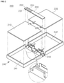
- FIG. 2 is a schematic view showing a battery pack according to an embodiment of the present invention, and referring to this, the battery pack 200 according to the present invention has a structure in which two battery cells 210 and 220 and one Battery Management Unit (BMU) 230 are mounted on one frame member 240.
- BMU Battery Management Unit
- the battery pack 200 may include one or more battery cells having a structure in which a positive terminal and a negative terminal protrude from at least one outer periphery.
- the battery cells 210 and 220 may be mounted on the cell mounting parts 241 and 242 provided at the frame member 240 to be described later, respectively.
- BMU Battery Management Unit
- the BMU 230 includes components (not shown) for controlling charging/discharging, cooling, and the like of the battery cells 210 and 220, and has a known configuration that is electrically connected to the positive and negative terminals of the battery cells 210 and 220 to control the overall operation of the battery cells 210 and 220.
- the BMU 230 may be mounted on the BMU mounting part 243 of the frame member 240 to be described later.
- the frame member 240 has a structure that entirely surrounds the outer peripheries of the battery cells 210 and 220 and the BMU 230 as shown in FIGS. 2 and 3 , and has a structure in which the upper and lower surfaces of the battery cells 210 and 220 are opened respectively.
- the cell mounting parts 241 and 242 has a configuration in which the battery cells 210 and 220 are mounted, respectively.
- the cell mounting parts 241 and 242 are formed on both sides of the frame member 240, respectively, and have a frame-shaped structure with open upper and lower surfaces. Therefore, the battery cells 210 and 220 mounted on the cell mounting parts 241 and 242 are mounted so that only their outer peripheries are wrapped.
- the BMU mounting part 243 has a configuration in which the BMU 230 is mounted.
- the BMU mounting part 243 is formed between the cell mounting parts 241 and 242, and the upper surface of the BMU mounting part 243, which is a surface opposite to the bottom surface of the BMU 230 mounting part, has an open structure. Accordingly, the BMU 230 can be mounted from the upper surface toward the bottom surface of the BMU mounting part 243.
- the partition 244 separates the cell mounting parts 241 and 242 from the BMU mounting part 243, and has a structure that stably fixes and supports the BMU 230 mounted on the BMU mounting part 243.
- FIG. 3 is a diagram showing a part of a partition.
- the partition 244 according to the present invention includes a first partition 244a, which is an area formed to have a predetermined first height from the bottom surface of the BMU mounting part 243, and a second partition 244b, which is an area formed by extending upward by a predetermined second height from a portion of the upper end of the first partition 244a.
- the partition 244 is composed of two regions having different heights, and these regions are referred to by being divided into the first partition 244a and the second partition 244b, respectively.
- the partition 244 composed of the first and second partitions 244a and 244b having different heights can prevent the stress generated by external vibrations or forces from being concentrated on the BMU 230 when the BMU 230 mounted on the BMU mounting part 243.
- FIG. 4 is a diagram schematically showing the principle of a partition structure according to the present invention.
- the conventional partition is made of a uniform height overall. Therefore, when external vibration or force is applied, since stress is concentrated in the BMU mounted on the BMU mounting part, there is a problem that the BMU components are damaged or broken.
- the partition of the present invention is composed of first and second partitions 244a and 244b, which are regions having different heights.
- first and second partitions 244a and 244b are regions having different heights.
- the partition 244 composed of the first and second partitions 244a and 244b having different heights according to the present invention has a structure that mitigates the concentration of stress generated by external vibration or force on the BMU 230.
- the partition 244 composed of the first and second partitions 244a and 244b having different heights according to the present invention has a structure that mitigates the concentration of stress generated by external vibration or force on the BMU 230.
- an experiment such as applying external vibration to the reliability test of the battery pack by this structure, in the process, there is an effect of reducing the occurrence of a problem of damage or breakage of components of the BMU 230. Furthermore, accordingly, it may result in improved productivity compared to the existing process.
- partition 244 structure consisting of first and second partitions 244a and 244b having different heights, the elasticity characteristics of the material of the frame member 240 are effectively exhibited. Accordingly, when the BMU 230 is mounted in the front direction of the BMU mounting part 243, as the partition 244 is pushed, the BMU 230 is inserted and mounted, thereby making it easier to mount the BMU
- the partition 244 may be formed to have a constant height from the bottom surface of the partition 244 as a whole, but may have a structure in which a hole 244c is formed in a lower region thereof.
- the hole 244c distributes the stress generated by external vibration or force, and thus, compared to the prior art, the concentration of stress on the BMU is alleviated, so that damage or breakage of BMU components can be reduced.
- the hole 244c is formed in the partition 244, like the second partition 244b of the first embodiment, at least two of the holes 244c may be formed at predetermined intervals.
- the partition 244 configured as described above has a form having an inclination a in the direction of the arrow shown in FIG. 2 , and specifically, may be formed to be inclined by a predetermined angle ⁇ in the direction of the cell mounting parts 241 and 242, respectively.
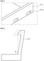
- FIG. 6 is a cross-sectional view schematically illustrating a view of one side partition of both partitions when viewed from the front.
- the partition 244 according to the present invention has a structure inclined by a predetermined angle ⁇ in the direction of the cell mounting parts.
- the partition 244 when assembling the BMU 230, as the partition 244 is composed of first and second partitions 244a and 244b having different heights, for example, it can be assembled by pressing the BMU 230 in the front direction of the BMU mounting part 243 using a pressing jig and mounting it. At this time, if the partition 244 is formed to be inclined by a predetermined angle ⁇ in the direction of the cell mounting parts 241 and 242, which is not vertical, the inclined partition 244 functions to easily position the BMU 230 on the front surface of the BMU mounting part 243. Therefore, it has an effect of improving the assembling property of the BMU 230 to the BMU mounting part 243.
- the partition 244 inclined by a predetermined angle ⁇ in the direction of the cell mounting parts 241 and 242 has a structure that absorbs the tolerance of the mounting position of the BMU 230 with respect to the BMU mounting part 243 and has an effect of improving the assembling property of the BMU 230.
- the predetermined angle ⁇ may be set within a range in which the partition 244 can effectively exhibit the above-described functions.
- At least two second partitions 244b formed by extending upward from the first partition 244a by a predetermined second height may be configured in one partition.
- two second partitions 244b are configured at regular intervals at the partition 244 separating the cell mounting part 241 and the BMU mounting part 243 in the left direction, and two second partitions 244b are formed at regular intervals at the partition 244 that divides the cell mounting part 242 and the BMU mounting part 243 in the right direction.
- the partition 244 is composed of first and second partitions 244a and 244b having different heights, and at least two or more of the second partitions 244b are formed at predetermined intervals.
- the partition 244 is designed to be inclined by a predetermined angle ⁇ in the direction of the cell mounting parts 241 and 242.
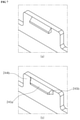
- the fixing part 245 is a configuration that allows the BMU 230 mounted on the BMU mounting part 243 to be stably fixed in its position, and as shown in FIG. 5 , may be provided on an inner wall of the second partition 244b facing the BMU mounting part 243.
- the fixing part 245 may include a protruding part 245a formed protruding from the second partition 244b by a predetermined length in the inner direction of the BMU mounting part 243 to fix the BMU 230 mounted on the BMU mounting part 243 so as not to be separated from the outside thereof and a connection support part 245b formed extending from both sides of the protruding part 245a toward the surface of the second partition 244b by a predetermined length in a curved shape to support the protruding part 245a to be stably connected to the second partition 244b.
- the length L protruding from the second partition 244b of the protruding part 245a in the inward direction of the BMU mounting part 243 may be set considering the degree to which the BMU 230 mounted on the BMU mounting part 243 can be stably fixed in its position.
- the length L can be applied with 0.5mm.
- the length R of the curved shape extending from both sides of the protruding part 245a in the direction of the second partition 244b may be set considering the degree to which the protruding part 245a can be stably fixed to the second partition 244b.
- the length R can be applied with 0.5mm.
- the protruding part 245a is more reliably connected to the second partition 244b so that it is possible to strengthen the rigidity of the protruding part 245a. Accordingly, the protruding part 245a can more effectively exhibit a function of fixing the BMU 230 to the BMU mounting part 243.
Landscapes
- Chemical & Material Sciences (AREA)
- Chemical Kinetics & Catalysis (AREA)
- Electrochemistry (AREA)
- General Chemical & Material Sciences (AREA)
- Engineering & Computer Science (AREA)
- Manufacturing & Machinery (AREA)
- Microelectronics & Electronic Packaging (AREA)
- Battery Mounting, Suspending (AREA)
- Sealing Battery Cases Or Jackets (AREA)
Abstract
Description
- The present invention relates to a battery pack including a structure for preventing damage to components of a battery management unit (BMU).
- Rechargeable secondary batteries are widely used in various fields ranging from electric vehicles and Energy Storage Systems (ESS) to small high-tech electronic devices such as smart phones, notebook computers, and tablet PCs.
- In order to exhibit the desired capacity characteristics within the applied device, in relation to these batteries, a plurality of battery cells are mounted on the frame member and connected in series or parallel, and these batteries are also used in the form of a battery pack including a Battery Management Unit (BMU) that controls the overall operation of the battery cells.
-
FIG. 1 is a view schematically showing the structure of a frame member constituting a conventional battery pack. - Referring to
FIG. 1 , thebattery pack 100 has a structure in which twobattery cells frame member 140. - The
frame member 140 has a structure that entirely surrounds the outer periphery of thebattery cells BMU 130, and twocell mounting parts battery cells frame member 140, respectively, and aBMU mounting part 143 on which theBMU 130 is mounted is formed between thecell mounting parts cell mounting parts BMU mounting part 143 are divided by partitions. - In this case, both partitions of the
BMU mounting part 143 have a structure having a uniform height as a whole while forming a right angle to the bottom surface. Accordingly, theBMU 130 is fitted in a diagonal direction from one side of theBMU mounting part 143 and mounted therein, and is fixed by hooks (not shown) provided at one end of both partitions of theBMU mounting part 143. - However, when an external force is applied to the
frame member 140, both partition structures of theBMU mounting part 143 as described above have a structure in which stress is concentrated in theBMU 130 mounted on theBMU mounting part 143. Accordingly, in a state in which thebattery cells BMU 130 are mounted on theframe member 140, when performing an experiment such as applying external vibration for the reliability test, in the process, the components of theBMU 130 are damaged or broken. - In addition, since the
BMU 130 mounted on theBMU mounting part 143 is fixed only by a hook (not shown), due to the low fixing force, situations such as frequent movement of theBMU 130 or separation from theBMU mounting part 143 occur in the above experimental process. Therefore, this also causes a problem in which the components of theBMU 130 are damaged or broken. - (Patent Document 1)
KR10-2016-0142975 A - The present invention is to solve the above-described problems, and to provide a battery pack including a structure capable of preventing damage to BMU components.
- A battery pack according to the present invention includes: two or more battery cells in which a positive terminal and a negative terminal protrude from one outer periphery; a Battery Management Unit (BMU) electrically connected to the positive terminal and the negative terminal of the battery cell to control an operation of the battery cells; and a frame member on which each of the battery cells and the BMU is respectively mounted, wherein the frame member includes: cell mounting parts on which the battery cells are mounted; a BMU mounting part on which the BMU is mounted; and a partition configured to divide the cell mounting parts and the BMU mounting part.
- Here, the cell mounting parts are formed in a frame-shaped structure with an open upper and lower surface, and are formed at both ends of the frame member to accommodate the battery cells; wherein the BMU mounting part has an open top surface, insertingly accommodates the BMU, and is formed between the cell mounting parts; wherein the partition includes two or more areas having different heights from the bottom surface of the BMU mounting part.
- In more detail, the partition includes: a first partition which is an area formed to have a predetermined first height from a bottom surface of the BMU mounting part; and a second partition formed by extending upward from an upper end portion area of the first partition by a predetermined second height.
- At this time, the second partition is formed at least two or more at a predetermined interval on both sides of the upper end of the first partition.
- Moreover, the battery pack further includes a fixing part for fixing the BMU mounted on the BMU mounting part, wherein the fixing part is formed on the inner wall facing the BMU mounting part of the second partition.
- In more detail, the fixing part includes: a protruding part protruding from the second partition by a predetermined length in an inward direction of the BMU mounting part to prevent separation of the BMU mounted on the BMU mounting part; and a connection support part extending from both sides of the protruding part toward an inner surface of the second partition by a predetermined length in a curved shape and supporting a connection between the second partition and the protruding part.
- Furthermore, the partition consisting of the first and second partitions is formed to have a slope inclined by a predetermined angle θ in the direction of the cell mounting parts.
- Moreover, the partition is formed to have a predetermined height as a whole with respect to the bottom surface of the BMU mounting part, wherein a hole is formed in a lower region thereof.
- Here, the hole is formed at least two or more at predetermined intervals in the length direction of the partition.
- Meanwhile, the battery pack configured as described above may be applied to devices including mobile phones, notebook computers, and tablet PCs.
- The battery pack of the present invention has a structure that prevents damage to the BMU components, so that even when external vibration or force is applied while the BMU is mounted on the frame member, the stress on the BMU is dispersed by the structure and the BMU is stably fixed at the mounting position.
- Accordingly, it is possible to effectively prevent damage to the BMU component parts, and further, improve the productivity of the battery pack compared to the existing process.
-
-
FIG. 1 is a view schematically showing the overall structure of a frame member constituting a conventional battery pack. -
FIG. 2 is a schematic view showing the overall structure of a frame member constituting a battery pack according to an embodiment of the present invention. -
FIG. 3 is a diagram illustrating an inner part of a partition according to an embodiment of the present invention. -
FIG. 4 is a diagram schematically showing the principle of a partition structure according to an embodiment of the present invention. -
FIG. 5 is a schematic diagram of a part of a partition structure according to another embodiment of the present invention -
FIG. 6 is a diagram schematically showing a state of one partition as viewed from the front. -
FIG. 7 is a view showing a fixing part according to an embodiment of the present invention. - Hereinafter, embodiments of the present invention will be described in detail with reference to the accompanying drawings so that those of ordinary skill in the art may easily implement the present invention. However, the present invention may be implemented in various forms and is not limited to the embodiments described herein. In the drawings, parts irrelevant to the description are omitted in order to clearly describe the present invention, and like reference numerals refer to like elements throughout the specification.
- Hereinafter, the present invention will be described in detail with reference to the drawings.
-
FIG. 2 is a schematic view showing a battery pack according to an embodiment of the present invention, and referring to this, thebattery pack 200 according to the present invention has a structure in which twobattery cells - The
battery pack 200 according to the present invention may include one or more battery cells having a structure in which a positive terminal and a negative terminal protrude from at least one outer periphery. Thebattery cells cell mounting parts - The BMU 230 includes components (not shown) for controlling charging/discharging, cooling, and the like of the
battery cells battery cells battery cells - In a state in which the external input/
output terminal 232 connected by thewire 231 protrudes outward from the outer periphery of the frame member 240, theBMU 230 may be mounted on theBMU mounting part 243 of the frame member 240 to be described later. - The frame member 240 has a structure that entirely surrounds the outer peripheries of the
battery cells BMU 230 as shown inFIGS. 2 and3 , and has a structure in which the upper and lower surfaces of thebattery cells - The
cell mounting parts battery cells cell mounting parts battery cells cell mounting parts - The
BMU mounting part 243 has a configuration in which theBMU 230 is mounted. TheBMU mounting part 243 is formed between thecell mounting parts BMU mounting part 243, which is a surface opposite to the bottom surface of theBMU 230 mounting part, has an open structure. Accordingly, theBMU 230 can be mounted from the upper surface toward the bottom surface of theBMU mounting part 243. - The
partition 244 separates thecell mounting parts BMU mounting part 243, and has a structure that stably fixes and supports theBMU 230 mounted on theBMU mounting part 243. - Specifically,
FIG. 3 is a diagram showing a part of a partition. Referring toFIG. 3 , thepartition 244 according to the present invention includes afirst partition 244a, which is an area formed to have a predetermined first height from the bottom surface of theBMU mounting part 243, and asecond partition 244b, which is an area formed by extending upward by a predetermined second height from a portion of the upper end of thefirst partition 244a. - In simple terms, the
partition 244 is composed of two regions having different heights, and these regions are referred to by being divided into thefirst partition 244a and thesecond partition 244b, respectively. - As described above, the
partition 244 composed of the first andsecond partitions BMU 230 when theBMU 230 mounted on theBMU mounting part 243. -
FIG. 4 is a diagram schematically showing the principle of a partition structure according to the present invention. As shown inFIG. 4A , the conventional partition is made of a uniform height overall. Therefore, when external vibration or force is applied, since stress is concentrated in the BMU mounted on the BMU mounting part, there is a problem that the BMU components are damaged or broken. - In order to improve this, as shown in
FIG. 4B , the partition of the present invention is composed of first andsecond partitions second partition 244b formed according to the height difference between thefirst partition 244a and thesecond partition 244b, it is possible to exert an effect of alleviating concentration in theBMU 230 by dispersing the stress generated by external vibration or force. - That is, the
partition 244 composed of the first andsecond partitions BMU 230. When conducting an experiment such as applying external vibration to the reliability test of the battery pack by this structure, in the process, there is an effect of reducing the occurrence of a problem of damage or breakage of components of theBMU 230. Furthermore, accordingly, it may result in improved productivity compared to the existing process. - In addition, by the
partition 244 structure consisting of first andsecond partitions BMU 230 is mounted in the front direction of theBMU mounting part 243, as thepartition 244 is pushed, theBMU 230 is inserted and mounted, thereby making it easier to mount the BMU - As another embodiment for alleviating the stress concentration on the BMU, as shown in
FIG. 5 , thepartition 244 may be formed to have a constant height from the bottom surface of thepartition 244 as a whole, but may have a structure in which ahole 244c is formed in a lower region thereof. - In the case of forming the
hole 244c, thehole 244c distributes the stress generated by external vibration or force, and thus, compared to the prior art, the concentration of stress on the BMU is alleviated, so that damage or breakage of BMU components can be reduced. - Here, even when the
hole 244c is formed in thepartition 244, like thesecond partition 244b of the first embodiment, at least two of theholes 244c may be formed at predetermined intervals. - On the other hand, the
partition 244 configured as described above has a form having an inclination a in the direction of the arrow shown inFIG. 2 , and specifically, may be formed to be inclined by a predetermined angle θ in the direction of thecell mounting parts -
FIG. 6 is a cross-sectional view schematically illustrating a view of one side partition of both partitions when viewed from the front. Referring to this, compared to the partition being at right angles to the bottom surface as indicated by dotted lines conventionally, thepartition 244 according to the present invention has a structure inclined by a predetermined angle θ in the direction of the cell mounting parts. - The reason is that when assembling the
BMU 230, as thepartition 244 is composed of first andsecond partitions BMU 230 in the front direction of theBMU mounting part 243 using a pressing jig and mounting it. At this time, if thepartition 244 is formed to be inclined by a predetermined angle θ in the direction of thecell mounting parts inclined partition 244 functions to easily position theBMU 230 on the front surface of theBMU mounting part 243. Therefore, it has an effect of improving the assembling property of theBMU 230 to theBMU mounting part 243. - In other words, the
partition 244 inclined by a predetermined angle θ in the direction of thecell mounting parts BMU 230 with respect to theBMU mounting part 243 and has an effect of improving the assembling property of theBMU 230. - Here, the predetermined angle θ may be set within a range in which the
partition 244 can effectively exhibit the above-described functions. - Meanwhile, at least two
second partitions 244b formed by extending upward from thefirst partition 244a by a predetermined second height may be configured in one partition. In order to maximize the stress concentration relaxation effect on theBMU 230, for example, it may be desirable to form twosecond partitions 244b at regular intervals. - In other words, based on the
BMU mounting part 243, it may be desirable that twosecond partitions 244b are configured at regular intervals at thepartition 244 separating thecell mounting part 241 and theBMU mounting part 243 in the left direction, and twosecond partitions 244b are formed at regular intervals at thepartition 244 that divides thecell mounting part 242 and theBMU mounting part 243 in the right direction. - As described above, in the present invention, the
partition 244 is composed of first andsecond partitions second partitions 244b are formed at predetermined intervals. In addition, thepartition 244 is designed to be inclined by a predetermined angle θ in the direction of thecell mounting parts - The fixing part 245 is a configuration that allows the
BMU 230 mounted on theBMU mounting part 243 to be stably fixed in its position, and as shown inFIG. 5 , may be provided on an inner wall of thesecond partition 244b facing theBMU mounting part 243. - Specifically, referring to the enlarged portion A of the fixing part in
FIG. 3 , the fixing part 245 may include aprotruding part 245a formed protruding from thesecond partition 244b by a predetermined length in the inner direction of theBMU mounting part 243 to fix theBMU 230 mounted on theBMU mounting part 243 so as not to be separated from the outside thereof and aconnection support part 245b formed extending from both sides of theprotruding part 245a toward the surface of thesecond partition 244b by a predetermined length in a curved shape to support the protrudingpart 245a to be stably connected to thesecond partition 244b. - Here, the length L protruding from the
second partition 244b of theprotruding part 245a in the inward direction of theBMU mounting part 243 may be set considering the degree to which theBMU 230 mounted on theBMU mounting part 243 can be stably fixed in its position. For example, the length L can be applied with 0.5mm. - In addition, the length R of the curved shape extending from both sides of the
protruding part 245a in the direction of thesecond partition 244b may be set considering the degree to which theprotruding part 245a can be stably fixed to thesecond partition 244b. For example, the length R can be applied with 0.5mm. - As shown in
FIG. 7 , unlike (a) showing a conventional fixing part structure, by additionally configuring asupport part 245b connected to both sides of theprotruding part 245a, the protrudingpart 245a is more reliably connected to thesecond partition 244b so that it is possible to strengthen the rigidity of theprotruding part 245a. Accordingly, the protrudingpart 245a can more effectively exhibit a function of fixing theBMU 230 to theBMU mounting part 243. - On the other hand, although the technical idea of the present invention has been specifically described according to the above embodiment, it should be noted that the above embodiments are for the purpose of explanation and not limitation. In addition, those skilled in the art in the technical field of the present invention will be able to understand that various embodiments are possible within the scope of the spirit of the present invention.
Claims (10)
- A battery pack comprising:two or more battery cells in which a positive terminal and a negative terminal protrude from one outer periphery;a Battery Management Unit (BMU) electrically connected to the positive terminal and the negative terminal of the battery cell to control an operation of the battery cells; anda frame member on which each of the battery cells and the BMU is respectively mounted,wherein the frame member comprises:cell mounting parts on which the battery cells are mounted;a BMU mounting part on which the BMU is mounted; anda partition configured to divide the cell mounting parts and the BMU mounting part.
- The battery pack of claim 1, wherein the cell mounting parts are formed in a frame-shaped structure with an open upper and lower surface, and are formed at both ends of the frame member to accommodate the battery cells;wherein the BMU mounting part has an open top surface, insertingly accommodates the BMU, and is formed between the cell mounting parts;wherein the partition comprises two or more areas having different heights from the bottom surface of the BMU mounting part.
- The battery pack of claim 2, wherein the partition comprises:a first partition which is an area formed to have a predetermined first height from a bottom surface of the BMU mounting part; anda second partition formed by extending upward from an upper end portion area of the first partition by a predetermined second height.
- The battery pack of claim 3, wherein the second partition is formed at least two or more at a predetermined interval on both sides of the upper end of the first partition.
- The battery pack of claim 3, further comprising a fixing part for fixing the BMU mounted on the BMU mounting part,
wherein the fixing part is formed on the inner wall facing the BMU mounting part of the second partition. - The battery pack of claim 5, wherein the fixing part comprises:a protruding part protruding from the second partition by a predetermined length in an inward direction of the BMU mounting part to prevent separation of the BMU mounted on the BMU mounting part; anda connection support part extending from both sides of the protruding part toward an inner surface of the second partition by a predetermined length in a curved shape and supporting a connection between the second partition and the protruding part.
- The battery pack of claim 3, wherein the partition consisting of the first and second partitions is formed to have a slope inclined by a predetermined angle θ in the direction of the cell mounting parts.
- The battery pack of claim 1, wherein the partition is formed to have a predetermined height as a whole with respect to the bottom surface of the BMU mounting part, wherein a hole is formed in a lower region thereof.
- The battery pack of claim 8, wherein the hole is formed at least two or more at predetermined intervals in the length direction of the partition.
- A device comprising the battery pack according to any one of claims 1 to 9.
Applications Claiming Priority (2)
| Application Number | Priority Date | Filing Date | Title |
|---|---|---|---|
| KR1020200004872A KR102837100B1 (en) | 2020-01-14 | 2020-01-14 | Battery packs with Battery Management Unit component damage prevention structure |
| PCT/KR2020/019420 WO2021145593A1 (en) | 2020-01-14 | 2020-12-30 | Battery pack having bmu component damage prevention structure |
Publications (2)
| Publication Number | Publication Date |
|---|---|
| EP3940861A1 true EP3940861A1 (en) | 2022-01-19 |
| EP3940861A4 EP3940861A4 (en) | 2022-06-01 |
Family
ID=76863234
Family Applications (1)
| Application Number | Title | Priority Date | Filing Date |
|---|---|---|---|
| EP20914606.7A Pending EP3940861A4 (en) | 2020-01-14 | 2020-12-30 | BATTERY PACK HAVING BMU COMPONENT DAMAGE PREVENTION STRUCTURE |
Country Status (6)
| Country | Link |
|---|---|
| US (1) | US12224408B2 (en) |
| EP (1) | EP3940861A4 (en) |
| JP (1) | JP7279188B2 (en) |
| KR (1) | KR102837100B1 (en) |
| CN (1) | CN113678309B (en) |
| WO (1) | WO2021145593A1 (en) |
Families Citing this family (2)
| Publication number | Priority date | Publication date | Assignee | Title |
|---|---|---|---|---|
| KR20230053153A (en) * | 2021-10-14 | 2023-04-21 | 주식회사 엘지에너지솔루션 | A Battery Module Having Excellent Impact Resistance |
| CN118589069B (en) * | 2024-05-29 | 2025-11-11 | 厦门科华数能科技有限公司 | Energy storage module of double BMU |
Family Cites Families (26)
| Publication number | Priority date | Publication date | Assignee | Title |
|---|---|---|---|---|
| TW438061U (en) | 1999-04-16 | 2001-05-28 | Hon Hai Prec Ind Co Ltd | Electrical connector |
| JP4488730B2 (en) * | 2003-12-22 | 2010-06-23 | 三洋電機株式会社 | Thin battery pack |
| KR101267082B1 (en) * | 2008-02-15 | 2013-05-23 | 엘지디스플레이 주식회사 | Back Light Unit And Liquid Crystal Display Using It |
| JP2010257605A (en) | 2009-04-21 | 2010-11-11 | Hitachi Maxell Ltd | Battery pack |
| KR101289282B1 (en) * | 2010-05-28 | 2013-07-24 | 주식회사 엘지화학 | Battery Pack of Compact Structure |
| KR101270593B1 (en) | 2010-07-16 | 2013-06-03 | 주식회사 엘지화학 | Pack Case of Novel Structure |
| JP5783706B2 (en) | 2010-11-05 | 2015-09-24 | キヤノン株式会社 | Printed circuit board |
| US9065085B2 (en) | 2011-04-19 | 2015-06-23 | Samsung Sdi Co., Ltd. | Battery pack |
| CN102852912A (en) | 2011-06-29 | 2013-01-02 | 珠海格力电器股份有限公司 | Screw connecting seat |
| CN202201238U (en) | 2011-09-01 | 2012-04-25 | 苏州良才物流科技股份有限公司 | A large size turnover box |
| KR101403384B1 (en) | 2011-12-20 | 2014-06-03 | 주식회사 엘지화학 | New Structured Battery Pack |
| JP5877114B2 (en) | 2012-04-02 | 2016-03-02 | 株式会社ホンマ・アーキライフ | Strength panel and building, structure and machine using the same |
| JP2014063598A (en) | 2012-09-03 | 2014-04-10 | Nec Energy Devices Ltd | Battery pack |
| KR101925934B1 (en) * | 2012-09-06 | 2018-12-06 | 삼성에스디아이 주식회사 | Battery pack |
| KR102018693B1 (en) | 2013-02-06 | 2019-09-05 | 삼성에스디아이 주식회사 | Rechargeable battery pack |
| WO2014155719A1 (en) * | 2013-03-29 | 2014-10-02 | 富士通株式会社 | Battery pack and electronic device |
| US20150037619A1 (en) | 2013-07-30 | 2015-02-05 | Samsung Sdi Co., Ltd. | Rechargeable battery pack |
| KR102082868B1 (en) | 2013-08-30 | 2020-02-28 | 삼성에스디아이 주식회사 | Battery Pack |
| KR102152364B1 (en) | 2013-12-05 | 2020-09-04 | 삼성에스디아이 주식회사 | Battery pack |
| JP6417856B2 (en) * | 2014-10-31 | 2018-11-07 | 住友電気工業株式会社 | Power storage device module |
| KR101520392B1 (en) * | 2014-11-26 | 2015-05-14 | 삼성에스디아이 주식회사 | Rechargeable battery |
| JP6497942B2 (en) | 2015-01-13 | 2019-04-10 | 日立オートモティブシステムズ株式会社 | Electronic control unit |
| KR102066914B1 (en) | 2015-06-04 | 2020-01-16 | 주식회사 엘지화학 | Battery Pack Comprising Pack Frame Having Holder for PCM |
| KR102066915B1 (en) | 2015-06-04 | 2020-01-16 | 주식회사 엘지화학 | Battery Pack Comprising Frame Member Having Hole for Welding |
| WO2017104108A1 (en) * | 2015-12-17 | 2017-06-22 | 三洋電機株式会社 | Battery pack |
| KR102221780B1 (en) * | 2017-05-04 | 2021-03-02 | 주식회사 엘지화학 | Battery pack and method for manufcturing the same |
-
2020
- 2020-01-14 KR KR1020200004872A patent/KR102837100B1/en active Active
- 2020-12-30 CN CN202080021408.0A patent/CN113678309B/en active Active
- 2020-12-30 WO PCT/KR2020/019420 patent/WO2021145593A1/en not_active Ceased
- 2020-12-30 EP EP20914606.7A patent/EP3940861A4/en active Pending
- 2020-12-30 JP JP2021556600A patent/JP7279188B2/en active Active
- 2020-12-30 US US17/632,854 patent/US12224408B2/en active Active
Also Published As
| Publication number | Publication date |
|---|---|
| EP3940861A4 (en) | 2022-06-01 |
| JP2022525796A (en) | 2022-05-19 |
| CN113678309B (en) | 2023-10-24 |
| KR102837100B1 (en) | 2025-07-22 |
| JP7279188B2 (en) | 2023-05-22 |
| US20220320599A1 (en) | 2022-10-06 |
| WO2021145593A1 (en) | 2021-07-22 |
| CN113678309A (en) | 2021-11-19 |
| KR20210091556A (en) | 2021-07-22 |
| US12224408B2 (en) | 2025-02-11 |
Similar Documents
| Publication | Publication Date | Title |
|---|---|---|
| US11342621B2 (en) | Battery pack | |
| EP2571078B1 (en) | Battery module | |
| US10135056B2 (en) | Energy storage device | |
| US10396323B2 (en) | Electrical box for battery pack and battery pack structure using same | |
| US11088388B2 (en) | Clamping member and battery module using the same | |
| EP2752919A1 (en) | Battery, assembled battery, and mounting device | |
| US12224408B2 (en) | Battery pack having BMU component damage prevention structure | |
| US20140242449A1 (en) | Pack Case for Battery | |
| US11205818B2 (en) | Cover assembly and battery module including the same | |
| US20140141306A1 (en) | Electric storage apparatus | |
| CN113381118B (en) | Rechargeable battery pack | |
| US20240380040A1 (en) | Battery Cell, and Battery Module, Battery Pack and Vehicle Including the Same | |
| EP4276995A1 (en) | Multi-battery pack having compact structure | |
| EP4120455A1 (en) | Power storage device and vehicle-mounted structure thereof | |
| US12107300B2 (en) | Energy storage device comprising current collector plate with spring portion | |
| KR101934397B1 (en) | Battery pack | |
| US8642192B2 (en) | Secondary battery | |
| JP2024129792A (en) | Battery pack | |
| KR102618035B1 (en) | Battery pack | |
| KR20080034625A (en) | Battery module | |
| US20260128444A1 (en) | Assembly structure of battery frame and battery package including the same | |
| EP4654356A1 (en) | Connector assembly | |
| EP4657671A1 (en) | Connector | |
| EP4668443A1 (en) | Energy storage system | |
| KR102328304B1 (en) | Second battery cell module and assembling method thereof |
Legal Events
| Date | Code | Title | Description |
|---|---|---|---|
| STAA | Information on the status of an ep patent application or granted ep patent |
Free format text: STATUS: THE INTERNATIONAL PUBLICATION HAS BEEN MADE |
|
| PUAI | Public reference made under article 153(3) epc to a published international application that has entered the european phase |
Free format text: ORIGINAL CODE: 0009012 |
|
| STAA | Information on the status of an ep patent application or granted ep patent |
Free format text: STATUS: REQUEST FOR EXAMINATION WAS MADE |
|
| 17P | Request for examination filed |
Effective date: 20211012 |
|
| AK | Designated contracting states |
Kind code of ref document: A1 Designated state(s): AL AT BE BG CH CY CZ DE DK EE ES FI FR GB GR HR HU IE IS IT LI LT LU LV MC MK MT NL NO PL PT RO RS SE SI SK SM TR |
|
| RAP3 | Party data changed (applicant data changed or rights of an application transferred) |
Owner name: LG ENERGY SOLUTION, LTD. |
|
| REG | Reference to a national code |
Ref country code: DE Ref legal event code: R079 Free format text: PREVIOUS MAIN CLASS: H01M0010420000 Ipc: H01M0050204000 |
|
| A4 | Supplementary search report drawn up and despatched |
Effective date: 20220503 |
|
| RIC1 | Information provided on ipc code assigned before grant |
Ipc: H01M 10/42 20060101ALI20220427BHEP Ipc: H01M 50/289 20210101ALI20220427BHEP Ipc: H01M 50/291 20210101ALI20220427BHEP Ipc: H01M 50/204 20210101AFI20220427BHEP |
|
| DAV | Request for validation of the european patent (deleted) | ||
| DAX | Request for extension of the european patent (deleted) | ||
| STAA | Information on the status of an ep patent application or granted ep patent |
Free format text: STATUS: EXAMINATION IS IN PROGRESS |
|
| 17Q | First examination report despatched |
Effective date: 20250120 |
|
| GRAP | Despatch of communication of intention to grant a patent |
Free format text: ORIGINAL CODE: EPIDOSNIGR1 |
|
| STAA | Information on the status of an ep patent application or granted ep patent |
Free format text: STATUS: GRANT OF PATENT IS INTENDED |
|
| INTG | Intention to grant announced |
Effective date: 20260206 |
|
| P01 | Opt-out of the competence of the unified patent court (upc) registered |
Free format text: CASE NUMBER: UPC_APP_0009365_3940861/2026 Effective date: 20260311 |