EP3940497A1 - Maximalflusseinstellung - Google Patents
Maximalflusseinstellung Download PDFInfo
- Publication number
- EP3940497A1 EP3940497A1 EP20216714.4A EP20216714A EP3940497A1 EP 3940497 A1 EP3940497 A1 EP 3940497A1 EP 20216714 A EP20216714 A EP 20216714A EP 3940497 A1 EP3940497 A1 EP 3940497A1
- Authority
- EP
- European Patent Office
- Prior art keywords
- series
- values
- bounded
- time series
- maximum
- Prior art date
- Legal status (The legal status is an assumption and is not a legal conclusion. Google has not performed a legal analysis and makes no representation as to the accuracy of the status listed.)
- Granted
Links
- 238000000034 method Methods 0.000 claims abstract description 99
- 238000004891 communication Methods 0.000 claims description 63
- 239000012530 fluid Substances 0.000 claims description 33
- 238000004590 computer program Methods 0.000 claims description 14
- 238000010438 heat treatment Methods 0.000 claims description 14
- 230000006870 function Effects 0.000 claims description 10
- 230000008859 change Effects 0.000 claims description 9
- 238000004378 air conditioning Methods 0.000 claims description 6
- 238000009423 ventilation Methods 0.000 claims description 6
- 238000009434 installation Methods 0.000 description 15
- 230000005540 biological transmission Effects 0.000 description 14
- LYCAIKOWRPUZTN-UHFFFAOYSA-N Ethylene glycol Chemical compound OCCO LYCAIKOWRPUZTN-UHFFFAOYSA-N 0.000 description 9
- DNIAPMSPPWPWGF-UHFFFAOYSA-N Propylene glycol Chemical compound CC(O)CO DNIAPMSPPWPWGF-UHFFFAOYSA-N 0.000 description 9
- 230000010363 phase shift Effects 0.000 description 6
- 239000003795 chemical substances by application Substances 0.000 description 4
- 238000001816 cooling Methods 0.000 description 4
- 238000013461 design Methods 0.000 description 4
- XLYOFNOQVPJJNP-UHFFFAOYSA-N water Substances O XLYOFNOQVPJJNP-UHFFFAOYSA-N 0.000 description 4
- 238000012423 maintenance Methods 0.000 description 3
- 239000000203 mixture Substances 0.000 description 3
- 230000008569 process Effects 0.000 description 3
- 238000012546 transfer Methods 0.000 description 3
- 238000009529 body temperature measurement Methods 0.000 description 2
- 230000001960 triggered effect Effects 0.000 description 2
- 238000012935 Averaging Methods 0.000 description 1
- 239000002826 coolant Substances 0.000 description 1
- 230000003993 interaction Effects 0.000 description 1
- 238000012986 modification Methods 0.000 description 1
- 230000004048 modification Effects 0.000 description 1
- 230000008439 repair process Effects 0.000 description 1
- 239000002699 waste material Substances 0.000 description 1
Images


Classifications
-
- F—MECHANICAL ENGINEERING; LIGHTING; HEATING; WEAPONS; BLASTING
- F24—HEATING; RANGES; VENTILATING
- F24F—AIR-CONDITIONING; AIR-HUMIDIFICATION; VENTILATION; USE OF AIR CURRENTS FOR SCREENING
- F24F11/00—Control or safety arrangements
- F24F11/50—Control or safety arrangements characterised by user interfaces or communication
- F24F11/54—Control or safety arrangements characterised by user interfaces or communication using one central controller connected to several sub-controllers
-
- G—PHYSICS
- G05—CONTROLLING; REGULATING
- G05D—SYSTEMS FOR CONTROLLING OR REGULATING NON-ELECTRIC VARIABLES
- G05D7/00—Control of flow
- G05D7/06—Control of flow characterised by the use of electric means
- G05D7/0617—Control of flow characterised by the use of electric means specially adapted for fluid materials
- G05D7/0629—Control of flow characterised by the use of electric means specially adapted for fluid materials characterised by the type of regulator means
- G05D7/0635—Control of flow characterised by the use of electric means specially adapted for fluid materials characterised by the type of regulator means by action on throttling means
-
- F—MECHANICAL ENGINEERING; LIGHTING; HEATING; WEAPONS; BLASTING
- F24—HEATING; RANGES; VENTILATING
- F24F—AIR-CONDITIONING; AIR-HUMIDIFICATION; VENTILATION; USE OF AIR CURRENTS FOR SCREENING
- F24F11/00—Control or safety arrangements
- F24F11/50—Control or safety arrangements characterised by user interfaces or communication
- F24F11/56—Remote control
-
- F—MECHANICAL ENGINEERING; LIGHTING; HEATING; WEAPONS; BLASTING
- F24—HEATING; RANGES; VENTILATING
- F24F—AIR-CONDITIONING; AIR-HUMIDIFICATION; VENTILATION; USE OF AIR CURRENTS FOR SCREENING
- F24F11/00—Control or safety arrangements
- F24F11/50—Control or safety arrangements characterised by user interfaces or communication
- F24F11/61—Control or safety arrangements characterised by user interfaces or communication using timers
-
- F—MECHANICAL ENGINEERING; LIGHTING; HEATING; WEAPONS; BLASTING
- F24—HEATING; RANGES; VENTILATING
- F24F—AIR-CONDITIONING; AIR-HUMIDIFICATION; VENTILATION; USE OF AIR CURRENTS FOR SCREENING
- F24F11/00—Control or safety arrangements
- F24F11/62—Control or safety arrangements characterised by the type of control or by internal processing, e.g. using fuzzy logic, adaptive control or estimation of values
- F24F11/63—Electronic processing
- F24F11/64—Electronic processing using pre-stored data
-
- F—MECHANICAL ENGINEERING; LIGHTING; HEATING; WEAPONS; BLASTING
- F24—HEATING; RANGES; VENTILATING
- F24F—AIR-CONDITIONING; AIR-HUMIDIFICATION; VENTILATION; USE OF AIR CURRENTS FOR SCREENING
- F24F11/00—Control or safety arrangements
- F24F11/70—Control systems characterised by their outputs; Constructional details thereof
- F24F11/80—Control systems characterised by their outputs; Constructional details thereof for controlling the temperature of the supplied air
- F24F11/83—Control systems characterised by their outputs; Constructional details thereof for controlling the temperature of the supplied air by controlling the supply of heat-exchange fluids to heat-exchangers
- F24F11/84—Control systems characterised by their outputs; Constructional details thereof for controlling the temperature of the supplied air by controlling the supply of heat-exchange fluids to heat-exchangers using valves
-
- F—MECHANICAL ENGINEERING; LIGHTING; HEATING; WEAPONS; BLASTING
- F24—HEATING; RANGES; VENTILATING
- F24F—AIR-CONDITIONING; AIR-HUMIDIFICATION; VENTILATION; USE OF AIR CURRENTS FOR SCREENING
- F24F11/00—Control or safety arrangements
- F24F11/88—Electrical aspects, e.g. circuits
-
- G—PHYSICS
- G01—MEASURING; TESTING
- G01F—MEASURING VOLUME, VOLUME FLOW, MASS FLOW OR LIQUID LEVEL; METERING BY VOLUME
- G01F1/00—Measuring the volume flow or mass flow of fluid or fluent solid material wherein the fluid passes through a meter in a continuous flow
- G01F1/05—Measuring the volume flow or mass flow of fluid or fluent solid material wherein the fluid passes through a meter in a continuous flow by using mechanical effects
- G01F1/20—Measuring the volume flow or mass flow of fluid or fluent solid material wherein the fluid passes through a meter in a continuous flow by using mechanical effects by detection of dynamic effects of the flow
- G01F1/32—Measuring the volume flow or mass flow of fluid or fluent solid material wherein the fluid passes through a meter in a continuous flow by using mechanical effects by detection of dynamic effects of the flow using swirl flowmeters
- G01F1/3209—Measuring the volume flow or mass flow of fluid or fluent solid material wherein the fluid passes through a meter in a continuous flow by using mechanical effects by detection of dynamic effects of the flow using swirl flowmeters using Karman vortices
-
- G—PHYSICS
- G01—MEASURING; TESTING
- G01F—MEASURING VOLUME, VOLUME FLOW, MASS FLOW OR LIQUID LEVEL; METERING BY VOLUME
- G01F1/00—Measuring the volume flow or mass flow of fluid or fluent solid material wherein the fluid passes through a meter in a continuous flow
- G01F1/66—Measuring the volume flow or mass flow of fluid or fluent solid material wherein the fluid passes through a meter in a continuous flow by measuring frequency, phase shift or propagation time of electromagnetic or other waves, e.g. using ultrasonic flowmeters
-
- G—PHYSICS
- G01—MEASURING; TESTING
- G01F—MEASURING VOLUME, VOLUME FLOW, MASS FLOW OR LIQUID LEVEL; METERING BY VOLUME
- G01F15/00—Details of, or accessories for, apparatus of groups G01F1/00 - G01F13/00 insofar as such details or appliances are not adapted to particular types of such apparatus
- G01F15/005—Valves
-
- H—ELECTRICITY
- H04—ELECTRIC COMMUNICATION TECHNIQUE
- H04W—WIRELESS COMMUNICATION NETWORKS
- H04W4/00—Services specially adapted for wireless communication networks; Facilities therefor
- H04W4/80—Services using short range communication, e.g. near-field communication [NFC], radio-frequency identification [RFID] or low energy communication
-
- F—MECHANICAL ENGINEERING; LIGHTING; HEATING; WEAPONS; BLASTING
- F16—ENGINEERING ELEMENTS AND UNITS; GENERAL MEASURES FOR PRODUCING AND MAINTAINING EFFECTIVE FUNCTIONING OF MACHINES OR INSTALLATIONS; THERMAL INSULATION IN GENERAL
- F16K—VALVES; TAPS; COCKS; ACTUATING-FLOATS; DEVICES FOR VENTING OR AERATING
- F16K37/00—Special means in or on valves or other cut-off apparatus for indicating or recording operation thereof, or for enabling an alarm to be given
- F16K37/0025—Electrical or magnetic means
- F16K37/0041—Electrical or magnetic means for measuring valve parameters
-
- G—PHYSICS
- G01—MEASURING; TESTING
- G01F—MEASURING VOLUME, VOLUME FLOW, MASS FLOW OR LIQUID LEVEL; METERING BY VOLUME
- G01F1/00—Measuring the volume flow or mass flow of fluid or fluent solid material wherein the fluid passes through a meter in a continuous flow
Definitions
- the present disclosure teaches a method and a device for estimating maximum flow through a heat exchanger. More specifically, the present disclosure focuses on maximum flow through a heat exchanger of an installation for heating, ventilation, and/or air-conditioning.
- HVAC heating, ventilation, and/or air-conditioning
- Each circuit comprises one or several terminal units to provide heating and/or cooling to various parts of a building.
- Terminal units can be heating devices and/or cooling devices.
- a terminal unit of a domestic heating system can be a heat exchanger such as a radiator.
- Hydraulic resistances relate pressure drop to flow of a heating medium or to flow of a coolant.
- HVAC installations such as heating systems often require hydronic balancing.
- Hydronic balancing overcomes issues due to different hydraulic resistances of the circuits of a HVAC installation. Hydronic balancing of heating installations of commercial, residential and/or industrial sites ensures that each circuit of a system experiences adequate flow.
- hydronic balancing is generally performed on a site as designed and/or as built. Since the hydraulic resistances of a HVAC installation vary throughout operation, flow in the heat exchangers of an installation can become inadequate and/or incorrect overtime.
- EP3428767A1 was filed by SIEMENS SCHWEIZ AG on 3 July 2018.
- EP3428767A1 claims a priority date of 11 July 2017.
- a patent application US2019/018432A1 was subsequently filed before the USPTO on 10 July 2018.
- a patent EP3428767B1 was granted in Europe on 11 December 2019.
- EP3428767A1 , EP3428767B1 , and US2019/018432A1 deal with control gain automation.
- a position of a valve of a heat exchanger is determined in accordance with EP3428767B1 from a set point value and from a default flow rate. Determination of the position of the valve involves an opening curve of the valve.
- the valve assembly of EP3428767B1 affords determinations of valve positions at flow rates that are substantially zero.
- the valve assembly of EP3428767B1 also affords determinations of valve positions after the design stage of a commercial, residential and/or industrial site. The determined valve positions do, however, depend on a default flow rate. That default flow rate can be inadequate because hydraulic resistances can change overtime.
- a patent application EP3115703A1 was filed by SIEMENS SCHWEIZ AG on 20 April 2016. The application was published on 11 January 2017. A European patent EP3115703B1 was granted on 18 March 2020.
- the patent application EP3115703A1 and the patent EP3115703B1 address control of heating, ventilation, air conditioning systems.
- limit positions are determined for each of the valves of the heat exchangers of a HVAC installation. The determination of limit positions involves temperature measurements and temperature rise quantities derived from the temperature measurements. Determinations of limit positions and of flow settings of valves in accordance with EP3115703B1 can be effected after the design stage of a building.
- EP3489591A1 was filed by SIEMENS SCHWEIZ AG on 18 October 2018. The application claims a priority date of 24 November 2017 and was published on 29 May 2019.
- EP3489591A1 discloses a smart thermal energy exchanger.
- EP3489591A1 teaches a control system limiting flow through a heat exchanger to a determined maximum flow value. Determination of the maximum flow value through a heat exchanger is based on a characteristic transfer function of the heat exchanger.
- the characteristic transfer function is derived from a plurality of values of heat exchanger effectiveness (HXeff).
- the characteristic transfer function is also derived from a plurality of flow values.
- the values of heat exchanger effectiveness (HXeff) and the flow values are recorded by the control system of EP3489591 A1 for various points in time. Determinations of maximum flow settings in accordance with EP3489591A1 can be carried out after the design stage of a building.
- the instant disclosure deals with maximum flow rates and/or with maximum flow settings of heat exchangers and/or of terminal units.
- the present disclosure affords determinations of such maximum flow rates where the hydraulic resistances of a HVAC installation change over time. That is, the instant disclosure affords determinations of such maximum flow rates and/or maximum flow settings after the design stage of a commercial, residential and/or industrial site.
- WO2010/010092A2 A patent application WO2010/010092A2 was filed by BELIMO HOLDING AG and by KELLER URS on 21 July 2009. The application was published on 28 January 2010.
- WO2010/010092A2 deals with a method for the hydraulic compensation and control of a heating or cooling system and compensation and control valve therefor.
- Transients within HVAC circuits can cause valve controllers of local heat exchangers to open positions of their valves. Those valve positions can in practice exceed the limits of what is necessary to comply with a demand for heating or for cooling. Excessive flow through the heat exchangers of the HVAC circuit results in waste of power. Excessive flow through the heat exchangers of the HVAC circuit can also result in additional wear of the moving parts of a valve.
- the instant disclosure introduces a dynamic maximum setting for valves of heat exchangers of a HVAC circuit. The dynamic maximum setting mitigates excessive flow through such heat exchangers and limits ramifications of transients within HVAC circuits.
- the present disclosure teaches a control algorithm that can be implemented by a valve controller and/or by a control system.
- the valve controller and/or the control system can, by way of non-limiting examples, be employed in an enclosed environment and/or in an installation and/or on a premise and/or in a building.
- the control algorithm reads a signal indicative of a flow rate and processes the signal into a measure of flow rate.
- the measure of flow rate is averaged by calculating and/or by determining an hourly mean. After averaging, a scale factor and a maximum filter are applied to the averaged signal. A further minimum filter is applied. As a result, the averaged value is bounded between a percentage value and a value of maximum flow.
- the value of maximum flow preferably is a value provided by a user.
- a maximum value filter is applied.
- the filter is triggered every few hours and has a window length that exceeds the trigger interval.
- the filter produces a dynamic maximum flow setting to be used by the valve controller and/or by the control system.
- the average value can be bounded between a percentage value such as twenty percent or thirty percent or fifty percent and a value of maximum flow.
- a percentage value such as twenty percent or thirty percent or fifty percent and a value of maximum flow.
- the aforementioned list of percentage values is not exhaustive. Algorithms employing low percentage values may require high amounts of computational power. Algorithms employing high percentage values incur a risk of producing dynamic maximum flow settings that are too high.
- the value is ideally bounded between a percentage value of or near thirty percent and a value of maximum flow.
- the maximum filter can be triggered every two hours, every four hours, every eight hours, or every twelve hours.
- This list of trigger intervals is not exhaustive. Short trigger intervals afford values of dynamic maximum flow with better granularity. That said, short trigger intervals involve high levels of computational power.
- the trigger interval is advantageously set to four hours.
- the window length of the maximum value filter can exceed twelve hours.
- the window length of the maximum value filter can also be twenty-four hours, forty-eight hours or even exceed ninety-six hours.
- the mentioned values of window lengths are not exhaustive.
- the window length of the maximum value filter also determines the granularity of the produced value of maximum flow. Short window lengths of the filter yield more nuanced and more granular values of dynamic maximum flow. However, short window lengths may also yield values of dynamic maximum flow that are too low.
- the window length of the moving maximum filter advantageously is twenty-four hours.
- a user may harness the user interface to provide variables affecting maximum flow.
- Valves such as control valves and/or control systems having user interfaces afford interactions between users and the algorithm. Maintenance personnel and/or building operators can then change the constraints of the algorithm during maintenance work and during repair work.
- a user may harness an application on the mobile device to enter variables affecting maximum flow.
- a valve such as a control valve and/or a control system can provide connectivity with mobile devices such as radio frequency connectivity.
- the values entered by a user are then forwarded from the application to a data transmission interface of the mobile device.
- the data transmission interface of the mobile device forwards these values to a data transmission interface of the valve or of the control system.
- the valve and/or the control system reads the variables affecting maximum flow from its interface and feeds them to its control algorithm.
- Solutions involving local user interfaces or user interfaces via mobile devices can also be configured via such interfaces.
- Users such as maintenance personnel and/or building operators may tune parameters such as trigger intervals and/or window lengths in accordance with local, specific needs. Also, settings such as percentages of maximum flow can change in accordance with a user's preferences.
- a valve such as a control valve and/or a valve associated with a heat exchanger implements the control algorithm.
- the valve thus locally controls its maximum flow rate.
- the solution can be retrofitted to legacy heat exchangers and/or to legacy terminal units. The solution confers advantages in terms of data privacy since signals and/or measures of flow rates need not be transmitted to a remote controller.
- a remote controller such as a cloud computer implements the control algorithm.
- a valve such as a control valve and/or a valve associated with a heat exchanger connects to the remote controller using a communication protocol and via a communication bus.
- the valve transmits signals indicative of flow rates and/or measures of flow rates to the remote controller.
- the remote controller leverages such flow rates and/or measures and computes a maximum flow rate.
- the maximum flow rate is transmitted back to the valve and/or to a controller of a HVAC installation.
- the valve and/or the controller of a HVAC installation then locally applies the maximum flow rate obtained from the remote controller. Solutions involving remote controllers such as cloud computers enable local valves and/or controllers of local HVAC installations having limited computational resources.
- the local controller is or comprises an inexpensive, low-power system on a chip microcontroller having integrated wireless connectivity.
- the chip microcontroller has a memory not exceeding one mebibyte.
- FIG 1 shows a valve (1) having an inlet port (2) and an outlet port (3).
- a fluid path (4) extends between the inlet port (2) and the outlet port (3).
- a valve member (6) such as a conical valve member and/or a ball-type valve member is situated in the fluid path.
- the valve member (6) can move to a closed position which obturates the fluid path (4).
- the valve member (6) can also move to an open position which opens the fluid path (4).
- An actuator (7) such as a valve actuator couples, preferably mechanically couples, to the valve member (6).
- the actuator (7) can couple to the valve member (6) via a stem.
- the actuator (7) is in operative communication with a controller (8) such as a valve controller (8) and/or a local controller (8).
- the controller (8) ideally connects to the actuator (7) via a digital-to-analog converter.
- the digital-to-analog converter produces analog output signals for the actuator (7) from digital output signals of the controller (8).
- An amplifier can further amplify the analog signals originating from the digital-to-analog converter.
- a flow sensor (5a, 5b) such as an ultrasonic flow sensor and/or a vortex flow sensor is in communication with the fluid path (4).
- the flow sensor (5a, 5b) as shown in FIG 1 is part of the valve (1). That is, the valve (1) has the flow sensor (5a, 5b).
- the flow sensor (5a, 5b) can also be separate from the valve (1).
- the controller (8) also has an interface for reading an input signal (9).
- the signal (9) can be an analog signal such as an analog signal in the range of several millivolts and/or an analog signal in the range from zero to twenty milliamperes.
- the signal (9) can also be a digital signal transmitted via a digital communication interface.
- the controller (8) of the valve (1) can implement an algorithm as illustrated in FIG 2 .
- the moving average filter (11) can be an hourly moving average filter.
- the moving average filter (11) can be an analog and/or a digital circuit comprised by the controller (8).
- the moving average filter (11) feeds its signals to an optional multiplier (12).
- the optional multiplier (12) multiplies the signals produced by the moving average filter (11) with a scale factor such as two or four or ten.
- the multiplier (12) can be an analog and/or a digital circuit comprised by the controller (8).
- a threshold filter (14) is then applied to the signals originating from the multiplier (12) and/or from the moving average filter (11).
- the threshold filter (14) replaces signals that are less than a threshold value (13) with that threshold value (13).
- the threshold filter (14) can be an analog and/or a digital circuit comprised by the controller (8).
- Another threshold filter (16) is afterwards applied to the signals originating from the previous threshold filter (14).
- the other threshold filter (16) replaces signals that exceed another threshold value (15) with that other threshold value (15).
- the threshold filter (16) can be an analog and/or a digital circuit comprised by the controller (8).
- a maximum filter (17) such as a moving maximum filter (17) is eventually employed to produce a maximum flow rate.
- the maximum filter (17) preferably returns the largest of its input signals over a given time span such as twenty-four hours.
- the maximum filter (17) can be an analog and/or a digital circuit comprised by the controller (8).
- the moving maximum filter (17) can be an analog and/or a digital circuit comprised by the controller (8).
- the controller (8) of the valve (1) uses the maximum flow rate produced by the maximum filter (17) to limit flow through the valve (1). To that end, the controller (8) limits the input signal (9) to that maximum flow rate. The controller (8) can also produce a maximum flow signal from the maximum flow rate and limit the input signal (9) to the maximum flow signal. The controller (8) then produces an actuation signal to be transmitted to the actuator (7).
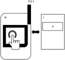
- FIG 3 shows the controller (8) of the valve (1) in operative communication with a mobile handheld device (18).
- the mobile handheld device (18) can, by way of non-limiting example, comprise a phone and/or a tablet computer.
- the mobile handheld device (18) preferably communicates with the controller (8) using a wireless communication bus such as a radio-frequent communication bus.
- the wireless communication bus can involve phase-shift keying and/or redundant data transmission. Phase-shift keying and/or redundant data transmission afford transmission of radio-frequent signals between the controller (8) and the mobile handheld device (18) in case of long distances between the two devices (8, 18). Phase-shift keying and/or redundant data transmission also afford transmission of radio-frequent signals between the controller (8) and the mobile handheld device (18) in case of attenuation caused by concrete walls or similar.
- the mobile handheld device (18) can be used to set a variable such as a filter variable and/or a process variable of the algorithm depicted in FIG 2 .
- the variable can, by way of non-limiting example, be a time constant and/or a window size of one of the filters (11, 17).
- the variable can, by way of another non-limiting example, be an upper limit or a lower limit to be factored in by one of the threshold filters (14, 16).
- FIG 4 shows the controller (8) of the valve (1) in operative communication with a remote controller (19).
- the remote controller (19) can, by way of non-limiting example, comprise a cloud computer and/or a server computer.
- the remote controller (19) preferably communicates with the controller (8) using a communication bus such as a radio-frequent communication bus.
- the radio-frequent communication bus can involve phase-shift keying and/or redundant data transmission.
- Phase-shift keying and/or redundant data transmission afford transmission of radio-frequent signals between the controller (8) of the valve (1) and the remote controller (19) in case of long distances between the two devices (8, 19).
- Phase-shift keying and/or redundant data transmission also afford transmission of radio-frequent signals between the controller (8) of the valve (1) and the remote controller (19) in case of attenuation caused by concrete walls or similar.
- the remote controller (19) can be used to set a variable such as a filter variable and/or a process variable of the algorithm depicted in FIG 2 .
- the variable can, by way of non-limiting example, be a time constant and/or a window size of one of the filters (11, 17).
- the variable can, by way of another non-limiting example, be an upper limit or a lower limit to be factored in by one of the threshold filters (14, 16).
- the remote controller (19) can also perform part of the control algorithm as illustrated in FIG 2 .
- the controller (8) of the valve (1) samples readings from the flow sensor (5a, 5b) and transmits these readings to the remote controller (19).
- the remote controller (19) performs the steps of the algorithm illustrated in FIG 2 and transmits a maximum flow rate back to the controller (8) of the valve (1).
- the controller (8) of the valve (1) then uses the maximum flow rate to limit flow through the valve (1) and/or flow along the fluid path (4).
- the controller (8) of the valve (1) produces flow rates from the signals sampled from the flow sensor (5a, 5b).
- the flow rates (5a, 5b) are then transferred to the remote controller (19) and processed as described above.
- valve (1) comprising a valve member (6) and an actuator (7) coupled to the valve member (6), the method comprising a plurality of iterations, each iteration comprising the steps of:
- the instant disclosure also teaches any of the aforementioned methods of limiting flow through a valve (1) comprising a valve member (6) and an actuator (7) coupled to the valve member (6),
- the present disclosure further teaches any of the aforementioned methods of limiting flow through a valve (1) comprising a valve member (6) and an actuator (7) coupled to the valve member (6),
- the controller (8) is or comprises a local controller (8).
- the local controller (8) is local at the valve (1).
- a remote controller (19) is not local at the valve (1).
- the remote controller (19) can, by way of non-limiting example, be arranged at a distance of at least ten metres or at least one hundred metres or even at least one kilometre from the valve (1).
- the actuation signal is preferably indicative of a position of the valve member (6). That is, the method comprises a plurality of iterations, each iteration comprising the steps of:
- valve (1) comprising a valve member (6) and an actuator (7) coupled to the valve member (6),
- the present disclosure yet further teaches any of the aforementioned methods of limiting flow through a valve (1) comprising a valve member (6) and an actuator (7) coupled to the valve member (6), wherein the method comprises a plurality of iterations, each iteration comprising the step of: producing an averaged series of values by applying a moving average filter (11) to the time series of flow rates, the moving average filter (11) determining a plurality of subsets of the time series of flow rates and calculating an arithmetic average for each subset of the plurality of subsets.
- the moving average filter (11) determines a plurality of subsets of the time series of flow rates, each subset of the plurality of subsets being at least thirty minutes long, and/or at least one hour long and/or at least two hours long. That is, the moving average filter (11) has a window size of at least thirty minutes or of at least one hour or of at least two hours.
- the instant disclosure also teaches any of the aforementioned methods of limiting flow through a valve (1) comprising a valve member (6) and an actuator (7) coupled to the valve member (6),
- the present disclosure further teaches any of the aforementioned methods of limiting flow through a valve (1) comprising a valve member (6) and an actuator (7) coupled to the valve member (6), wherein the method comprises a plurality of iterations, each iteration comprising the step of: producing an averaged series of values by applying a moving average filter (11) to the time series of flow rates, the moving average filter (11) determining a plurality of subsets of the time series of flow rates and calculating a geometric average for each subset of the plurality of subsets. It is envisaged that the moving average filter (11) determines a plurality of subsets of the time series of flow rates, each subset being at least thirty minutes long, and/or at least one hour long and/or at least two hours long. That is, the moving average filter (11) has a window size of at least thirty minutes or of at least one hour or of at least two hours.
- valve (1) comprising a valve member (6) and an actuator (7) coupled to the valve member (6),
- the instant disclosure also teaches any of the methods of limiting flow through a valve (1) as described above, the method comprising a plurality of iterations, each iteration comprising the step of: changing the time series of flow rates by multiplying each flow rate of the time series of flow rates with a scale factor.
- the scale factor is a predetermined scale factor.
- the scale factor advantageously is the same for all flow rates of the time series of flow rates.
- the present disclosure teaches any of the aforementioned methods of limiting flow through a valve (1) comprising a valve member (6) and an actuator (7) coupled to the valve member (6),
- the present disclosure teaches any of the aforementioned methods of limiting flow through a valve (1) comprising a valve member (6) and an actuator (7) coupled to the valve member (6),
- valve (1) comprising a valve member (6) and an actuator (7) coupled to the valve member (6),
- the first threshold filter (14) is or comprises a less than filter.
- the less than filter replaces any value below the lower threshold (13) with a value that equals the lower threshold (13).
- the instant disclosure also teaches any of the aforementioned methods of limiting flow through a valve (1) comprising a valve member (6) and an actuator (7) coupled to the valve member (6),
- the second threshold filter (16) is or comprises a greater than filter.
- the greater than filter replaces any value above the upper threshold (15) with a value that equals the upper threshold (15).
- the present disclosure still teaches any of the methods of limiting flow through a valve (1) comprising a valve member (6) and an actuator (7) coupled to the valve member (6) as described herein, wherein the method comprises a plurality of iterations, each iteration comprising the steps of:
- the present disclosure further teaches any of the methods of limiting flow through a valve (1) comprising a valve member (6) and an actuator (7) coupled to the valve member (6) as described herein,
- the maximum filter (17) has a window size of the maximum filter (17) and the second bounded series has a length.
- the window size of the maximum filer (17) exceeds the length of the second bounded series. That is, the method comprises a plurality of iterations, each iteration comprising the step of: producing a maximum flow rate by applying a maximum filter (17) to the second bounded series, the second bounded series having a length and the maximum filter (17) having window size exceeding the length of the second bounded series, the maximum filter (17) returning the largest value of the second bounded series.
- the window size of the maximum filter (17) is a time span of the maximum filter (17).
- the second bounded series also has a time span.
- the time span of the maximum filter (17) advantageously exceeds the time span of the second bounded series.
- the instant disclosure still further teaches any of the methods of limiting flow through a valve (1) comprising a valve member (6) and an actuator (7) coupled to the valve member (6) as described herein, wherein the method comprises a plurality of iterations, each iteration comprising the step of: applying the produced maximum flow rate as a maximum flow setting to the valve (1) such that the valve (1) limits flow through the valve (1) to the produced maximum flow rate.
- valve (1) comprising a valve member (6) and an actuator (7) coupled to the valve member (6),
- the present disclosure also teaches any of the aforementioned methods of limiting flow through a valve (1) comprising a valve member (6) and an actuator (7) coupled to the valve member (6),
- the instant disclosure further teaches any of the aforementioned methods of limiting flow through a valve (1) comprising a valve member (6) and an actuator (7) coupled to the valve member (6), wherein the method comprises a plurality of iterations, each iteration comprising the steps of:
- the instant disclosure further teaches any of the aforementioned methods of limiting flow through a valve (1) comprising a valve member (6) and an actuator (7) coupled to the valve member (6),
- the present disclosure still further teaches any of the aforementioned methods of limiting flow through a valve (1) comprising a valve member (6) and an actuator (7) coupled to the valve member (6), wherein the method comprises a plurality of iterations, each iteration comprising the steps of:
- valve (1) comprising a valve member (6) and an actuator (7) coupled to the valve member (6),
- the present disclosure also teaches any of the aforementioned methods of limiting flow through a valve (1) comprising a valve member (6) and an actuator (7) coupled to the valve member (6),
- the present disclosure further teaches any of the methods of limiting flow through a valve (1) as described above, the method comprising the steps of:
- the present disclosure also teaches any of the aforementioned methods of limiting flow through a valve (1) comprising a valve member (6) and an actuator (7) coupled to the valve member (6), the method comprising a plurality of iterations, each iteration comprising the steps of:
- the step of connecting to a mobile handheld device (18) involves connecting to a mobile handheld device (18) using a digital communication bus.
- the digital communication bus preferably comprises a wireless communication bus.
- the mobile handheld device (18) comprises a mobile phone and/or a tablet computer.
- the present disclosure also teaches any of the aforementioned methods of limiting flow through a valve (1) comprising a valve member (6) and an actuator (7) coupled to the valve member (6), the method comprising a plurality of iterations, each iteration comprising the steps of:
- the step of connecting to a remote controller (19) involves connecting to a remote controller (19) using a digital communication bus.
- the digital communication bus preferably comprises a wireless communication bus.
- the present disclosure still teaches any of the methods of limiting flow through a valve (1) as described above,
- the remote controller (19) comprises a cloud computer. It is envisaged that the local controller (8) comprises a microcontroller (8) and/or a microprocessor (8).
- the instant disclosure also teaches any of the aforementioned methods of limiting flow through a valve (1) comprising a valve member (6) and an actuator (7) coupled to the valve member (6), the method involving a local controller (8) and a remote controller (19), the method comprising a plurality of iterations, each iteration comprising the steps of:
- the instant disclosure also teaches any of the aforementioned methods of limiting flow through a valve (1) comprising a valve member (6) and an actuator (7) coupled to the valve member (6), the method involving a local controller (8) and a remote controller (19), the method comprising a plurality of iterations, each iteration comprising the steps of:
- any of the aforementioned methods involving a local controller (8) and a remote controller (19) comprises a plurality of iterations, each iteration comprising the step of: the remote controller (19) changing the time series of flow rates by multiplying each flow rate of the time series of flow rates with a scale factor.
- the local controller (8) is different from the remote controller (19).
- the present disclosure yet further teaches an application of any of the aforementioned methods to limit flow through a valve (1) of a system for heating, ventilation, and/or air-conditioning.
- the instant disclosure also teaches an application of any of the aforementioned methods of limiting flow through a valve (1) to limit flow through a valve (1) of an installation for heating, ventilation, and/or air-conditioning.
- the set point signal (9) advantageously is a single set point signal.
- the set point signal (9) does ideally not comprise a time series of signals or positions.
- these methods comprise a plurality of iterations, wherein the plurality of iterations comprises two or more iterations. It is also envisaged that the plurality of iterations can comprise five or more iterations or even ten or more iterations.
- the methods disclosed above comprise a plurality of iterations to be performed consecutively, each consecutive iteration comprising the steps specified above.
- the methods disclosed above comprise a plurality of iterations to be performed repeatedly, each repeated iteration comprising the steps specified above.
- valve (1) comprising:
- the flow sensor (5a, 5b) is not part of the valve (1). In an alternate embodiment, the flow sensor (5a, 5b) is part of the valve (1).
- the actuator (7) of the valve (1) advantageously is or comprises a valve actuator (7).
- the actuator (7) of the valve (1) preferably couples to the valve member (6) of the valve (1).
- the actuator (7) of the valve (1) can be or can comprise a solenoid actuator.
- the controller (8) is or comprises a valve controller (8) such as a microcontroller (8) and/or a microprocessor (8). It is also envisaged that the controller (8) is or comprises a local controller (8) such as a microcontroller (8) and/or a microprocessor (8). The controller (8) and/or the valve controller (8) and/or the local controller (8) and/or the microcontroller (8) and/or the microprocessor (8) can be mounted to the valve body.
- the actuator (7) is mounted to the valve body. It is also envisaged that the valve member (6) is secured relative to the valve body and/or that the valve member (6) is mounted to the valve body.
- valve (1) is a fluid flow such as
- the flow advantageously takes place along the fluid path (4) of the valve (1).
- the valve (1) advantageously has a controller (8) such as a microcontroller (8) and/or a microprocessor (8).
- the valve (1) ideally is or comprises a control valve.
- controller (8) of the valve (1) is configured to iteratively:
- valves (1) as described above, comprising:
- the flow sensor (5a, 5b) is in communication with the fluid path (4) for sensing a flow rate of a fluid flowing along the fluid path (4). It is still envisaged that the flow sensor (5a, 5b) is in communication with the fluid path (4) for sensing a flow rate of a fluid flowing through the fluid path (4).
- the flow sensor (5a, 5b) is mounted to the valve body.
- the valve (1) preferably has a flow sensor (5a, 5b).
- the flow sensor (5a, 5b) can be arranged along the fluid path (4) and/or outside the fluid path (4) and/or in the fluid path (4).
- the flow sensor (5a, 5b) can, by way of non-limiting example, be an ultrasonic flow sensor and/or a vortex flow sensor.
- the scale factor is a predetermined scale factor.
- the scale factor advantageously is the same for all flow rates of the time series of flow rates.
- the input interface of the controller (8) comprises an analog input port and/or an analog input pin.
- the input interface of the controller (8) can be an analog input port of a microcontroller (8) and/or an analog input port of a microprocessor (8).
- the input interface of the controller (8) can also be an analog input pin of a microcontroller (8) and/or an analog input pin of a microprocessor (8).
- the input interface of the controller (8) comprises a digital input port and/or a digital input pin.
- the input interface of the controller (8) can be a digital input port of a microcontroller (8) and/or a digital input port of a microprocessor (8).
- the input interface of the controller (8) can also be a digital input pin of a microcontroller (8) and/or a digital input pin of a microprocessor (8).
- the controller (8) comprises a screen having a graphical user interface and/or a touch screen having a graphical user interface.
- the screen and/or the touch screen forms the input interface of the controller (8).
- the actuation signal is preferably indicative of a position of the valve member (6). That is, the controller (8) of the valve (1) is configured to iteratively:
- the set point signal (9) advantageously is a single set point signal.
- the set point signal (9) does ideally not comprise a time series of signals or positions.
- valves (1) As to the aforementioned valves (1), it is envisaged that the controllers (8) of these valves (1) are configured to iteratively perform the specified steps in at least two iterations, in at least five iterations or even in at least ten iterations.
- controllers (8) of the valves (1) disclosed above are configured to perform the steps as specified in consecutive iterations.
- controllers (8) of the valves (1) disclosed above are configured to perform the steps as specified repeatedly in iterations.
- the instant disclosure also teaches a computer program comprising instructions to cause the controller (8) of any of the aforementioned valves (1) to execute the steps of any of the aforementioned methods not involving transmission of flow signals and/or flow rates between a local controller (8) and a remote controller (19).
- the present disclosure further teaches a computer program product comprising instructions to cause the controller (8) of any of the aforementioned valves (1) to execute the steps of any of the aforementioned methods of limiting flow through a valve (1).
- the instant disclosure still teaches a computer-readable medium having stored thereon any of the aforementioned computer programs.
- the present disclosure still further teaches a computer program comprising instructions which, when the program is executed by a local controller (8), cause the local controller (8) to iteratively:
- the set point signal (9) preferably is indicative of a flow rate through a valve (1) controlled by the local controller (8).
- the local controller (8) is configured to limit the set point signal (9) as a function of the maximum flow rate. According to a related aspect of the present disclosure, the local controller (8) is configured to iteratively:
- the instant disclosure yet further teaches a computer program comprising instructions which, when the program is executed by a remote controller (19), cause the remote controller (19) to iteratively:
- the maximum filter (17) is or comprises a moving maximum filter.
- the remote controller (19) is configured to iteratively: change the time series of flow rates by multiplying each flow rate of the time series of flow rates with a scale factor.
- the computer program comprises instructions which, when the program is executed by a remote controller (19), cause the remote controller (19) to iteratively:
- the set point signal (9) advantageously is a single set point signal.
- the set point signal (9) does ideally not comprise a time series of signals or positions.
- these computer programs comprise instructions, which, when the program is executed by a local controller (8) or by a remote controller (19), perform a plurality of iterations comprising the steps as specified, wherein the plurality of iterations comprises two or more iterations. It is also envisaged that the plurality of iterations can comprise five or more iterations or even ten or more iterations.
- a computer program disclosed above comprises instructions, which, when the program is executed by a local controller (8) or by a remote controller (19), perform a plurality of consecutive iterations, each consecutive iteration having the specified steps.
- a computer program disclosed above comprises instructions, which, when the program is executed by a local controller (8) or by a remote controller (19), perform a plurality of repeated iterations, each repeated iteration having the specified steps.
Landscapes
- Engineering & Computer Science (AREA)
- General Engineering & Computer Science (AREA)
- Chemical & Material Sciences (AREA)
- Combustion & Propulsion (AREA)
- Mechanical Engineering (AREA)
- Physics & Mathematics (AREA)
- Signal Processing (AREA)
- General Physics & Mathematics (AREA)
- Fluid Mechanics (AREA)
- Human Computer Interaction (AREA)
- Mathematical Physics (AREA)
- Fuzzy Systems (AREA)
- Automation & Control Theory (AREA)
- Computer Networks & Wireless Communication (AREA)
- Electromagnetism (AREA)
- Flow Control (AREA)
- Feedback Control In General (AREA)
Priority Applications (2)
| Application Number | Priority Date | Filing Date | Title |
|---|---|---|---|
| US17/373,887 US11614757B2 (en) | 2020-07-15 | 2021-07-13 | Estimating a maximum flow through a heat exchanger |
| CN202110800371.8A CN113944993B (zh) | 2020-07-15 | 2021-07-15 | 最大流设置 |
Applications Claiming Priority (1)
| Application Number | Priority Date | Filing Date | Title |
|---|---|---|---|
| EP20185888 | 2020-07-15 |
Publications (2)
| Publication Number | Publication Date |
|---|---|
| EP3940497A1 true EP3940497A1 (de) | 2022-01-19 |
| EP3940497B1 EP3940497B1 (de) | 2023-03-15 |
Family
ID=71620255
Family Applications (1)
| Application Number | Title | Priority Date | Filing Date |
|---|---|---|---|
| EP20216714.4A Active EP3940497B1 (de) | 2020-07-15 | 2020-12-22 | Maximalflusseinstellung |
Country Status (3)
| Country | Link |
|---|---|
| US (1) | US11614757B2 (de) |
| EP (1) | EP3940497B1 (de) |
| CN (1) | CN113944993B (de) |
Families Citing this family (1)
| Publication number | Priority date | Publication date | Assignee | Title |
|---|---|---|---|---|
| CN112013506B (zh) * | 2019-05-31 | 2022-02-25 | 青岛海尔空调电子有限公司 | 用于通讯检测的方法及装置、空调 |
Citations (4)
| Publication number | Priority date | Publication date | Assignee | Title |
|---|---|---|---|---|
| WO2010010092A2 (de) | 2008-07-25 | 2010-01-28 | Belimo Holding Ag | Verfahren für den hydraulischen abgleich und regelung einer heizungs- oder kühlanlage und abgleich- und regelventil dafür |
| EP3115703A1 (de) | 2015-07-03 | 2017-01-11 | Siemens Schweiz AG | Steuerung von heizung, lüftung, klimatisierung |
| EP3428767A1 (de) | 2017-07-11 | 2019-01-16 | Siemens Schweiz AG | Steuerungsverstärkungsautomatisierung |
| EP3489591A1 (de) | 2017-11-24 | 2019-05-29 | Siemens Schweiz AG | Intelligenter wärmeenergietauscher |
Family Cites Families (6)
| Publication number | Priority date | Publication date | Assignee | Title |
|---|---|---|---|---|
| US6033302A (en) * | 1997-11-07 | 2000-03-07 | Siemens Building Technologies, Inc. | Room pressure control apparatus having feedforward and feedback control and method |
| JP5101581B2 (ja) * | 2009-08-25 | 2012-12-19 | 株式会社堀場エステック | 流量制御装置 |
| CN102927666B (zh) * | 2012-11-30 | 2015-02-25 | 天津市金硕科技投资集团有限公司 | 中央空调智能控制系统和控制方法 |
| WO2014143922A1 (en) * | 2013-03-15 | 2014-09-18 | Schneider Electric Buildings, Llc | Advanced valve actuator with true flow feedback |
| DK179765B1 (en) * | 2017-11-10 | 2019-05-14 | Danfoss A/S | A METHOD FOR CONTROLLING A FLUID FLOW THROUGH A VALVE |
| CN110470039B (zh) * | 2019-09-06 | 2021-06-11 | 创新奇智(重庆)科技有限公司 | 一种基于最优控制理论的空调水阀调节方法 |
-
2020
- 2020-12-22 EP EP20216714.4A patent/EP3940497B1/de active Active
-
2021
- 2021-07-13 US US17/373,887 patent/US11614757B2/en active Active
- 2021-07-15 CN CN202110800371.8A patent/CN113944993B/zh active Active
Patent Citations (7)
| Publication number | Priority date | Publication date | Assignee | Title |
|---|---|---|---|---|
| WO2010010092A2 (de) | 2008-07-25 | 2010-01-28 | Belimo Holding Ag | Verfahren für den hydraulischen abgleich und regelung einer heizungs- oder kühlanlage und abgleich- und regelventil dafür |
| EP3115703A1 (de) | 2015-07-03 | 2017-01-11 | Siemens Schweiz AG | Steuerung von heizung, lüftung, klimatisierung |
| EP3115703B1 (de) | 2015-07-03 | 2020-03-18 | Siemens Schweiz AG | Steuerung von heizung, lüftung, klimatisierung |
| EP3428767A1 (de) | 2017-07-11 | 2019-01-16 | Siemens Schweiz AG | Steuerungsverstärkungsautomatisierung |
| US20190018432A1 (en) | 2017-07-11 | 2019-01-17 | Siemens Schweiz Ag | Control Gain Automation |
| EP3428767B1 (de) | 2017-07-11 | 2019-12-11 | Siemens Schweiz AG | Steuerungsverstärkungsautomatisierung |
| EP3489591A1 (de) | 2017-11-24 | 2019-05-29 | Siemens Schweiz AG | Intelligenter wärmeenergietauscher |
Also Published As
| Publication number | Publication date |
|---|---|
| EP3940497B1 (de) | 2023-03-15 |
| CN113944993A (zh) | 2022-01-18 |
| US11614757B2 (en) | 2023-03-28 |
| CN113944993B (zh) | 2023-06-09 |
| US20220019249A1 (en) | 2022-01-20 |
Similar Documents
| Publication | Publication Date | Title |
|---|---|---|
| US9631831B2 (en) | Method for controlling the opening of an HVAC valve based on the energy-per-flow gradient | |
| EP2997430B1 (de) | Vorrichtung und verfahren zur steuerung der öffnung eines ventils in einem hlk-system | |
| EP3940497B1 (de) | Maximalflusseinstellung | |
| CN109764243B (zh) | 用于控制通过阀的流体流动的方法 | |
| US7500453B2 (en) | Boiler control unit | |
| JP6194410B2 (ja) | モニタリングシステム | |
| CN104037103A (zh) | 故障检测系统及故障检测方法 | |
| JPH11218354A (ja) | フィードフォーワードとフィードバック制御を有する室圧制御装置および方法 | |
| CN105683661B (zh) | 用于匹配加热曲线的方法 | |
| CN109032200B (zh) | 半导体生产用温控设备及其电子膨胀阀的控制方法 | |
| CN110686386A (zh) | 区域控制方法、装置、系统及空调系统 | |
| WO2019027762A1 (en) | PLUMBING CONTROL DEVICE | |
| CN104242835A (zh) | 一种基于fpga的超短波电台alc控制系统和方法 | |
| JP4353301B2 (ja) | 空調制御の仲介装置、空調制御システム、空調制御方法および空調制御プログラム | |
| CN112393300A (zh) | 一种厨房集气罩的控制方法及控制系统 | |
| CN114183928B (zh) | 热水器、热水器的控制方法和相关设备 | |
| EP4038322B1 (de) | Vorrichtung und verfahren zur regelung eines heiz- und/oder kühlsystems | |
| US11047582B2 (en) | Method and devices for controlling a fluid transportation network | |
| CN202349310U (zh) | 集成能量感知功能的节流控制一体化的智慧阀门 | |
| EP1801508A1 (de) | System und Verfahren zur optimierten Verwaltung eines Heizsystems | |
| CZ2002602A3 (cs) | Způsob regulace teploty vzduchu v místnosti | |
| CN210018927U (zh) | 一种具有自动温控检测功能的煮锅 | |
| EP2442038A2 (de) | Integrierte Vorrichtung zur Erfassung der von Heizkörpern abgegebenene Wärme und zum Steuern eines Thermostatventils | |
| EP3825614A1 (de) | Sicherstellung einer strömung eines wärmeübertragungsfluids in einem fernwärme-/-kühlungsnetz | |
| CN205787946U (zh) | 1,4丁烯二醇加氢反应恒温控制系统 |
Legal Events
| Date | Code | Title | Description |
|---|---|---|---|
| STAA | Information on the status of an ep patent application or granted ep patent |
Free format text: STATUS: EXAMINATION IS IN PROGRESS |
|
| PUAI | Public reference made under article 153(3) epc to a published international application that has entered the european phase |
Free format text: ORIGINAL CODE: 0009012 |
|
| 17P | Request for examination filed |
Effective date: 20210705 |
|
| AK | Designated contracting states |
Kind code of ref document: A1 Designated state(s): AL AT BE BG CH CY CZ DE DK EE ES FI FR GB GR HR HU IE IS IT LI LT LU LV MC MK MT NL NO PL PT RO RS SE SI SK SM TR |
|
| INTG | Intention to grant announced |
Effective date: 20221021 |
|
| GRAS | Grant fee paid |
Free format text: ORIGINAL CODE: EPIDOSNIGR3 |
|
| STAA | Information on the status of an ep patent application or granted ep patent |
Free format text: STATUS: GRANT OF PATENT IS INTENDED |
|
| GRAA | (expected) grant |
Free format text: ORIGINAL CODE: 0009210 |
|
| STAA | Information on the status of an ep patent application or granted ep patent |
Free format text: STATUS: THE PATENT HAS BEEN GRANTED |
|
| AK | Designated contracting states |
Kind code of ref document: B1 Designated state(s): AL AT BE BG CH CY CZ DE DK EE ES FI FR GB GR HR HU IE IS IT LI LT LU LV MC MK MT NL NO PL PT RO RS SE SI SK SM TR |
|
| REG | Reference to a national code |
Ref country code: CH Ref legal event code: EP Ref country code: GB Ref legal event code: FG4D |
|
| REG | Reference to a national code |
Ref country code: DE Ref legal event code: R096 Ref document number: 602020008863 Country of ref document: DE |
|
| REG | Reference to a national code |
Ref country code: IE Ref legal event code: FG4D |
|
| REG | Reference to a national code |
Ref country code: AT Ref legal event code: REF Ref document number: 1554369 Country of ref document: AT Kind code of ref document: T Effective date: 20230415 |
|
| REG | Reference to a national code |
Ref country code: LT Ref legal event code: MG9D |
|
| REG | Reference to a national code |
Ref country code: NL Ref legal event code: MP Effective date: 20230315 |
|
| PG25 | Lapsed in a contracting state [announced via postgrant information from national office to epo] |
Ref country code: RS Free format text: LAPSE BECAUSE OF FAILURE TO SUBMIT A TRANSLATION OF THE DESCRIPTION OR TO PAY THE FEE WITHIN THE PRESCRIBED TIME-LIMIT Effective date: 20230315 Ref country code: NO Free format text: LAPSE BECAUSE OF FAILURE TO SUBMIT A TRANSLATION OF THE DESCRIPTION OR TO PAY THE FEE WITHIN THE PRESCRIBED TIME-LIMIT Effective date: 20230615 Ref country code: LV Free format text: LAPSE BECAUSE OF FAILURE TO SUBMIT A TRANSLATION OF THE DESCRIPTION OR TO PAY THE FEE WITHIN THE PRESCRIBED TIME-LIMIT Effective date: 20230315 Ref country code: LT Free format text: LAPSE BECAUSE OF FAILURE TO SUBMIT A TRANSLATION OF THE DESCRIPTION OR TO PAY THE FEE WITHIN THE PRESCRIBED TIME-LIMIT Effective date: 20230315 Ref country code: HR Free format text: LAPSE BECAUSE OF FAILURE TO SUBMIT A TRANSLATION OF THE DESCRIPTION OR TO PAY THE FEE WITHIN THE PRESCRIBED TIME-LIMIT Effective date: 20230315 |
|
| REG | Reference to a national code |
Ref country code: AT Ref legal event code: MK05 Ref document number: 1554369 Country of ref document: AT Kind code of ref document: T Effective date: 20230315 |
|
| PG25 | Lapsed in a contracting state [announced via postgrant information from national office to epo] |
Ref country code: SE Free format text: LAPSE BECAUSE OF FAILURE TO SUBMIT A TRANSLATION OF THE DESCRIPTION OR TO PAY THE FEE WITHIN THE PRESCRIBED TIME-LIMIT Effective date: 20230315 Ref country code: NL Free format text: LAPSE BECAUSE OF FAILURE TO SUBMIT A TRANSLATION OF THE DESCRIPTION OR TO PAY THE FEE WITHIN THE PRESCRIBED TIME-LIMIT Effective date: 20230315 Ref country code: GR Free format text: LAPSE BECAUSE OF FAILURE TO SUBMIT A TRANSLATION OF THE DESCRIPTION OR TO PAY THE FEE WITHIN THE PRESCRIBED TIME-LIMIT Effective date: 20230616 Ref country code: FI Free format text: LAPSE BECAUSE OF FAILURE TO SUBMIT A TRANSLATION OF THE DESCRIPTION OR TO PAY THE FEE WITHIN THE PRESCRIBED TIME-LIMIT Effective date: 20230315 |
|
| PG25 | Lapsed in a contracting state [announced via postgrant information from national office to epo] |
Ref country code: SM Free format text: LAPSE BECAUSE OF FAILURE TO SUBMIT A TRANSLATION OF THE DESCRIPTION OR TO PAY THE FEE WITHIN THE PRESCRIBED TIME-LIMIT Effective date: 20230315 Ref country code: RO Free format text: LAPSE BECAUSE OF FAILURE TO SUBMIT A TRANSLATION OF THE DESCRIPTION OR TO PAY THE FEE WITHIN THE PRESCRIBED TIME-LIMIT Effective date: 20230315 Ref country code: PT Free format text: LAPSE BECAUSE OF FAILURE TO SUBMIT A TRANSLATION OF THE DESCRIPTION OR TO PAY THE FEE WITHIN THE PRESCRIBED TIME-LIMIT Effective date: 20230717 Ref country code: ES Free format text: LAPSE BECAUSE OF FAILURE TO SUBMIT A TRANSLATION OF THE DESCRIPTION OR TO PAY THE FEE WITHIN THE PRESCRIBED TIME-LIMIT Effective date: 20230315 Ref country code: EE Free format text: LAPSE BECAUSE OF FAILURE TO SUBMIT A TRANSLATION OF THE DESCRIPTION OR TO PAY THE FEE WITHIN THE PRESCRIBED TIME-LIMIT Effective date: 20230315 Ref country code: CZ Free format text: LAPSE BECAUSE OF FAILURE TO SUBMIT A TRANSLATION OF THE DESCRIPTION OR TO PAY THE FEE WITHIN THE PRESCRIBED TIME-LIMIT Effective date: 20230315 Ref country code: AT Free format text: LAPSE BECAUSE OF FAILURE TO SUBMIT A TRANSLATION OF THE DESCRIPTION OR TO PAY THE FEE WITHIN THE PRESCRIBED TIME-LIMIT Effective date: 20230315 |
|
| PG25 | Lapsed in a contracting state [announced via postgrant information from national office to epo] |
Ref country code: SK Free format text: LAPSE BECAUSE OF FAILURE TO SUBMIT A TRANSLATION OF THE DESCRIPTION OR TO PAY THE FEE WITHIN THE PRESCRIBED TIME-LIMIT Effective date: 20230315 Ref country code: PL Free format text: LAPSE BECAUSE OF FAILURE TO SUBMIT A TRANSLATION OF THE DESCRIPTION OR TO PAY THE FEE WITHIN THE PRESCRIBED TIME-LIMIT Effective date: 20230315 Ref country code: IS Free format text: LAPSE BECAUSE OF FAILURE TO SUBMIT A TRANSLATION OF THE DESCRIPTION OR TO PAY THE FEE WITHIN THE PRESCRIBED TIME-LIMIT Effective date: 20230715 |
|
| REG | Reference to a national code |
Ref country code: DE Ref legal event code: R097 Ref document number: 602020008863 Country of ref document: DE |
|
| PLBE | No opposition filed within time limit |
Free format text: ORIGINAL CODE: 0009261 |
|
| STAA | Information on the status of an ep patent application or granted ep patent |
Free format text: STATUS: NO OPPOSITION FILED WITHIN TIME LIMIT |
|
| PG25 | Lapsed in a contracting state [announced via postgrant information from national office to epo] |
Ref country code: SI Free format text: LAPSE BECAUSE OF FAILURE TO SUBMIT A TRANSLATION OF THE DESCRIPTION OR TO PAY THE FEE WITHIN THE PRESCRIBED TIME-LIMIT Effective date: 20230315 Ref country code: DK Free format text: LAPSE BECAUSE OF FAILURE TO SUBMIT A TRANSLATION OF THE DESCRIPTION OR TO PAY THE FEE WITHIN THE PRESCRIBED TIME-LIMIT Effective date: 20230315 |
|
| PGFP | Annual fee paid to national office [announced via postgrant information from national office to epo] |
Ref country code: FR Payment date: 20231214 Year of fee payment: 4 |
|
| 26N | No opposition filed |
Effective date: 20231218 |
|
| PGFP | Annual fee paid to national office [announced via postgrant information from national office to epo] |
Ref country code: DE Payment date: 20240219 Year of fee payment: 4 Ref country code: CH Payment date: 20240305 Year of fee payment: 4 |