EP3940478A1 - Control system, control method, and control program - Google Patents
Control system, control method, and control program Download PDFInfo
- Publication number
- EP3940478A1 EP3940478A1 EP20773918.6A EP20773918A EP3940478A1 EP 3940478 A1 EP3940478 A1 EP 3940478A1 EP 20773918 A EP20773918 A EP 20773918A EP 3940478 A1 EP3940478 A1 EP 3940478A1
- Authority
- EP
- European Patent Office
- Prior art keywords
- sql statement
- data
- corrected
- controller
- display
- Prior art date
- Legal status (The legal status is an assumption and is not a legal conclusion. Google has not performed a legal analysis and makes no representation as to the accuracy of the status listed.)
- Pending
Links
Images








Classifications
-
- G—PHYSICS
- G05—CONTROLLING; REGULATING
- G05B—CONTROL OR REGULATING SYSTEMS IN GENERAL; FUNCTIONAL ELEMENTS OF SUCH SYSTEMS; MONITORING OR TESTING ARRANGEMENTS FOR SUCH SYSTEMS OR ELEMENTS
- G05B19/00—Program-control systems
- G05B19/02—Program-control systems electric
- G05B19/04—Program control other than numerical control, i.e. in sequence controllers or logic controllers
- G05B19/05—Programmable logic controllers, e.g. simulating logic interconnections of signals according to ladder diagrams or function charts
- G05B19/056—Programming the PLC
-
- G—PHYSICS
- G06—COMPUTING OR CALCULATING; COUNTING
- G06F—ELECTRIC DIGITAL DATA PROCESSING
- G06F11/00—Error detection; Error correction; Monitoring
- G06F11/07—Responding to the occurrence of a fault, e.g. fault tolerance
- G06F11/0703—Error or fault processing not based on redundancy, i.e. by taking additional measures to deal with the error or fault not making use of redundancy in operation, in hardware, or in data representation
- G06F11/0706—Error or fault processing not based on redundancy, i.e. by taking additional measures to deal with the error or fault not making use of redundancy in operation, in hardware, or in data representation the processing taking place on a specific hardware platform or in a specific software environment
- G06F11/0727—Error or fault processing not based on redundancy, i.e. by taking additional measures to deal with the error or fault not making use of redundancy in operation, in hardware, or in data representation the processing taking place on a specific hardware platform or in a specific software environment in a storage system, e.g. in a DASD or network based storage system
-
- G—PHYSICS
- G06—COMPUTING OR CALCULATING; COUNTING
- G06F—ELECTRIC DIGITAL DATA PROCESSING
- G06F11/00—Error detection; Error correction; Monitoring
- G06F11/07—Responding to the occurrence of a fault, e.g. fault tolerance
- G06F11/0703—Error or fault processing not based on redundancy, i.e. by taking additional measures to deal with the error or fault not making use of redundancy in operation, in hardware, or in data representation
- G06F11/079—Root cause analysis, i.e. error or fault diagnosis
-
- G—PHYSICS
- G06—COMPUTING OR CALCULATING; COUNTING
- G06F—ELECTRIC DIGITAL DATA PROCESSING
- G06F16/00—Information retrieval; Database structures therefor; File system structures therefor
- G06F16/20—Information retrieval; Database structures therefor; File system structures therefor of structured data, e.g. relational data
- G06F16/24—Querying
- G06F16/242—Query formulation
- G06F16/2423—Interactive query statement specification based on a database schema
-
- G—PHYSICS
- G06—COMPUTING OR CALCULATING; COUNTING
- G06F—ELECTRIC DIGITAL DATA PROCESSING
- G06F16/00—Information retrieval; Database structures therefor; File system structures therefor
- G06F16/20—Information retrieval; Database structures therefor; File system structures therefor of structured data, e.g. relational data
- G06F16/24—Querying
- G06F16/245—Query processing
- G06F16/2455—Query execution
-
- G—PHYSICS
- G06—COMPUTING OR CALCULATING; COUNTING
- G06F—ELECTRIC DIGITAL DATA PROCESSING
- G06F16/00—Information retrieval; Database structures therefor; File system structures therefor
- G06F16/20—Information retrieval; Database structures therefor; File system structures therefor of structured data, e.g. relational data
- G06F16/24—Querying
- G06F16/245—Query processing
- G06F16/2455—Query execution
- G06F16/24552—Database cache management
-
- G—PHYSICS
- G06—COMPUTING OR CALCULATING; COUNTING
- G06F—ELECTRIC DIGITAL DATA PROCESSING
- G06F17/00—Digital computing or data processing equipment or methods, specially adapted for specific functions
- G06F17/40—Data acquisition and logging
-
- G—PHYSICS
- G06—COMPUTING OR CALCULATING; COUNTING
- G06F—ELECTRIC DIGITAL DATA PROCESSING
- G06F11/00—Error detection; Error correction; Monitoring
- G06F11/07—Responding to the occurrence of a fault, e.g. fault tolerance
- G06F11/0703—Error or fault processing not based on redundancy, i.e. by taking additional measures to deal with the error or fault not making use of redundancy in operation, in hardware, or in data representation
- G06F11/0766—Error or fault reporting or storing
- G06F11/0787—Storage of error reports, e.g. persistent data storage, storage using memory protection
Definitions
- the present disclosure relates to a technique for generating tables on a data base to be accessed by a controller.
- the FA system includes an input apparatus, a drive apparatus, a controller, and the like.
- the controller controls the drive apparatus in accordance with inputs from various sensors as input devices.
- the drive apparatus includes, for example, a transporting plate for transporting a workpiece, a conveyor for conveying a workpiece, and an arm robot for transporting a workpiece to a predetermined target location.
- Japanese Patent Laid-Open No. 2016-194808 discloses a technique capable of operating a data base without the description of SQL and capable of collectively operating a plurality of records with a simple configuration.
- WO2014/184962 discloses a controller capable of reducing the number of steps of reading data from a data base as compared with a conventional method.
- Data related to a control target such as a drive apparatus is collected by a controller, and the collected data is sequentially added to the data base. At this time, the collected data may not be properly added to the data base due to some kinds of errors. In this case, the user needs to determine the cause of error and correct the SQL statement, the configuration or the like. The error may be caused by various factors, and depending on the type of errors, it is very difficult to determine the cause thereof. Accordingly, such a technique is desired that assists users in determining the cause of an error that occurs during the addition of collected data to a data base.
- An embodiment of the present disclosure provides an information processing device configured to communicate with a controller configured to a control target.
- Any of the controller and the information processing device includes a storage device configured to store one or more SQL statements to be executed so as to insert data related to the control target into a data base and an execution result of each of the one or more SQL statements in association with each other as log data.
- the information processing device includes a display unit, a display control unit configured to display on the display unit an SQL statement to be corrected which is among the SQL statements included in the log data and has an unsuccessful execution result, an operation unit configured to accept a correction operation on the SQL statement to be corrected and an execution operation on the corrected SQL statement, and a communication unit configured to send an execution instruction to execute the corrected SQL statement to the controller upon receipt of the execution operation by the operation unit and to receive an execution result of the corrected SQL statement from the controller.
- the display control unit displays an execution result of the corrected SQL statement on the display unit.
- the operation unit is further configured to accept an operation of selecting, from the SQL statements included in the log data, an SQL statement to be compared which has a successful execution result, and the display control unit displays the data inserted into the data base by the SQL statement to be corrected and the data inserted into the data base by the SQL statement to be compared side by side.
- the display control unit displays a set of data satisfying a predetermined comparison condition among the entire data set composed of data inserted into the data base by the SQL statement to be corrected and data inserted into the data base by the SQL statement to be compared in a display mode different from the other data in the data set.
- the predetermined comparison condition is satisfied when the number of digits is different between the data in the data set.
- the display control unit displays on the display unit an SQL statement among the SQL statements included in the log data that matches a part of the SQL statement to be corrected as a candidate of the SQL statement to be compared, and the operation unit accepts a selection operation of selecting the SQL statement to be compared from the candidates.
- the display control unit displays on the display unit an SQL statement among the SQL statements included in the log data that matches a table name defined in the SQL statement to be corrected as the candidate.
- Another embodiment of the present disclosure provides a control method of an information processing device configured to communicate with a controller that controls a control target.
- Any of the controller and the information processing device includes a storage device configured to store one or more SQL statements to be executed so as to insert data related to the control target into a data base and an execution result of each of the one or more SQL statements in association with each other as log data.
- the control method includes: displaying on the display unit an SQL statement to be corrected which is among the SQL statements included in the log data and has an unsuccessful execution result; accepting a correction operation on the SQL statement to be corrected and an execution operation on the corrected SQL statement; sending an execution instruction to execute the corrected SQL statement to the controller upon receipt of the execution operation and receiving from the controller an execution result of the corrected SQL statement; and displaying an execution result of the corrected SQL statement on the display unit.
- Another embodiment of the present disclosure provides a control program for an information processing device configured to communicate with a controller that controls a control target.
- Any of the controller and the information processing device includes a storage device configured to store one or more SQL statements to be executed so as to insert data related to the control target into a data base and an execution result of each of the one or more SQL statements in association with each other as log data.
- the control program causes the information processing device to perform: displaying on the display unit an SQL statement to be corrected which is among the SQL statements included in the log data and has an unsuccessful execution result; accepting a correction operation on the SQL statement to be corrected and an execution operation on the corrected SQL statement; sending an execution instruction to execute the corrected SQL statement to the controller upon receipt of the execution operation and receiving from the controller an execution result of the corrected SQL statement; and displaying an execution result of the corrected SQL statement on the display unit.
- Fig. 1 is a diagram illustrating an example configuration of a control system 10 according to an embodiment.
- the control system 10 is an FA (Factory Automation) system for automating a production process.
- the control system 10 includes one or more information processing devices 100, one or more controllers 200, one or more drive apparatuses 300, and one or more external apparatuses 400.
- the information processing device 100, the controller 200, and the external apparatus 400 are connected to a network NW1.
- the network NW1 may be an EtherNET, an OPC-UA (Object Linking and Embedding for Process Control Unified Architecture), or the like.
- the OPC-UA is a communication standard for realizing data exchange without depending on the type of vendor or OS (Operating System).
- the controller 200 and the drive apparatus 300 are connected to a network NW2.
- the network NW2 is preferably a field network that performs constant-period communication to guarantee the arrival time of data.
- the field network that performs constant-period communication is known as an EtherCAT (registered trademark), an EtherNet/IP (registered trademark), a CompoNet (registered trademark), or the like.
- the information processing device 100 may be, for example, a notebook PC (Personal Computer) or a desktop PC, a tablet terminal, a smartphone, or the other information processing terminal.
- the hardware configuration of the information processing device 100 includes a processor 102, an operation unit 115, and a display unit 121.
- the controller 200 may be, for example, a PLC (Programmable Logic Controller).
- the controller 200 controls the drive apparatus 300 in accordance with a pre-determined user program.
- the drive apparatus 300 includes various industrial apparatuses for automating a production process.
- the drive apparatus 300 may be a robot controller, a servo driver, an arm robot controlled by the robot controller, a servo motor controlled by the servo driver, or the like.
- the drive apparatus 300 may be a visual sensor which photographs a workpiece, any other devices used in a production process, or the like.
- the controller 200 collects various kinds of data indicating the state of the drive apparatus 300 to be controlled, and periodically adds the collected data to a data base 430 on the external apparatus 400.
- the collected data may be added to the data base 430 at a predetermined time when a control input is made or when the execution is completed.
- the data base 430 on the external apparatus 400 is constituted by one or more tables 432 generated in advance.
- the table 432 includes vertical fields as columns and horizontal fields as records. The collected data is added to the table 432 defined by the SQL statement.
- the controller 200 stores the result of adding the collected data to the data base 430 in the storage device 208 as log data 214.
- each SQL statement executed so as to add the collected data into the data base 430 is associated with the execution result of each SQL statement. For example, if a SQL statement is successfully executed, a symbol "OK" indicating that the execution result is successful is written to the log data 214 together with the executed SQL statement. On the other hand, if the SQL statement is not successfully executed, a symbol "NG" indicating that the execution result is unsuccessful is written to the log data 214 together with the executed SQL statement. Preferably, an error code is further written to the log data 214.
- the error code includes, for example, an error code indicating a connection error, an error code indicating that the right side of a character string is discarded, an error code indicating that the data is out of a data range, an error code indicating that the format of date and time is invalid, or the like.
- the information processing device 100 assists the user in determining the cause of an error that occurs during the addition of the collected data to the data base 430.
- the processor 102 provides a communication unit 152 and a display control unit 154.
- the communication unit 152 is implemented by a communication driver that establishes communication with the controller 200.
- the communication unit 152 receives the log data 214 from the controller 200, and outputs the received log data 214 to the display control unit 154.
- the display control unit 154 is a functional module that controls the contents to be displayed on the display unit 121.
- the display control unit 154 displays on the display unit 121 an edit screen 50 for editing an SQL statement.
- the edit screen 50 includes an SQL statement edit field 51, a record information display field 55, a send button 56, and a result display field 58.
- the display control unit 154 displays in the edit field 51 an SQL statement 52 which is among the SQL statements included in the log data 214 and has an unsuccessful execution result. Further, the display control unit 154 displays in the record information display field 55 the details of data unsuccessfully inserted by the SQL statement 52.
- the contents displayed in the record information display field 55 include the name of a table for the data insertion, the name of each field in the table, and the value of the unsuccessfully inserted data.
- the operation unit 115 accepts various user operations on the information processing device 100. As an example, the operation unit 115 accepts a correction operation to correct the SQL statement 52 displayed in the edit field 51. The operation unit 115 accepts an execution operation to execute the corrected SQL statement 52. The execution operation is accepted, for example, when the send button 56 on the edit screen 50 is pressed.
- the communication unit 152 sends the corrected SQL statement 52 and an execution instruction to execute the corrected SQL statement 52 to the controller 200 after the operation unit 115 accepts an execution operation.
- the controller 200 causes the external apparatus 400 to execute the corrected SQL statement 52 upon receipt of the corrected SQL statement 52 and the execution instruction from the information processing device 100. Thereafter, the controller 200 sends the execution result of the corrected SQL statement 52 to the information processing device 100.
- the communication unit 152 of the information processing device 100 outputs the execution result to the display control unit 154 upon receipt of the execution result from the controller 200. Then, the display control unit 154 displays on the display unit 121 the execution result received from the communication unit 152. In the example of Fig. 1 , the execution result of the corrected SQL statement 52 is displayed in the execution result display field 58 on the edit screen 50.
- the information processing device 100 displays on the display unit 121 the SQL statement 52 to be corrected which is among the SQL statements included in the log data 214 and has an unsuccessful execution result. Then, the information processing device 100 accepts a correction operation to correct the displayed SQL statement 52 and an execution operation to execute a test on the corrected SQL statement 52.
- the user may easily determine the cause of an error that occurs during the addition of the collected data to a data base, and may correct the SQL statement or the configuration in accordance with the determined cause.
- the data base 430 is provided on the external apparatus 400, it is not necessary that the data base 430 is provided on the external apparatus 400.
- the data base 430 may be provided on the controller 200.
- the data base 430 may be provided on a separate unit connected to the controller 200 via an internal bus.
- the writing function to the data base and the log storing function may be implemented on an unit attached to the controller 200.
- the log data 214 may be stored in the information processing device 100 instead of the controller 200.
- the hardware configuration of the information processing device 100, the hardware configuration of the controller 200, and the hardware configuration of the external apparatus 400 will be described in order with reference to Figs. 2 to 4 .
- Fig. 2 is a schematic diagram illustrating a hardware configuration of the information processing device 100.
- the information processing device 100 is, for example, a computer constructed according to a general-purpose computer architecture.
- the information processing device 100 includes a processor 102 such as a CPU (Central Processing Unit) or an MPU (Micro-Processing Unit), a main memory 104, a nonvolatile storage device 110, a communication interface 111, an I/O (Input/Output) interface 114, and a display interface 120. These components are communicatively connected to each other via an internal bus 125.
- the processor 102 controls the operation of the information processing device 100 by executing various control programs such as a development support program 110A.
- the development support program 110A is such a program that provides an environment for developing a control program (user program) of the controller 200.
- the processor 102 Upon receipt of an execution instruction to execute various control programs such as the development support program 110A, the processor 102 reads out a target control program from the storage device 110 into the main memory 104.
- the communication interface 111 exchanges data with the other communication devices via network.
- the other communication devices include, for example, a controller 200, an external apparatus 400, and a server.
- the information processing device 100 may be configured to download various control programs such as the development support program 110A from the other communication device via the communication interface 111.
- the I/O interface 114 is connected to the operation unit 115, and is configured to receive from the operation unit 115 a signal indicating a user operation.
- the operation unit 115 typically includes a keyboard, a mouse, a touch panel, a touch pad or the like, and accepts operations from a user.
- the information processing device 100 and the operation unit 115 are illustrated as separate units, but the information processing device 100 and the operation unit 115 may be constructed as an integral unit.
- the display interface 120 is connected to the display unit 121, and is configured to send to the display unit 121 an image signal for displaying an image in accordance with an instruction from the processor 102 or the like.
- the display unit 121 may be, for example, an LCD (Liquid Crystal Display) or an organic EL (Electro Luminescence) display, and is configured to present various kinds of information to the user.
- the display unit 121 may display various screens provided by the development support program 110A.
- the information processing device 100 and the display unit 121 are illustrated as separate units, but the information processor 100 and the display unit 121 may be constructed as an integral unit.
- Fig. 3 is a schematic diagram illustrating a hardware configuration of the controller 200.
- the controller 200 includes a communication interface 201, a processor 202 such as a CPU or MPU, a chipset 204, a main memory 206, a nonvolatile storage device 208, an internal bus controller 222, a field bus controller 224, and a memory card interface 239.
- the processor 202 controls various drive apparatuses 300 by reading out the control program 211 stored in the storage device 208, developing the control program 211 in the main memory 206, and executing the control program 211.
- the control program 211 includes various programs for controlling the controller 200.
- the control program 211 includes a system program 209, a user program 210 or the like.
- the system program 209 includes instruction codes for providing basic functions of the controller 200 such as data input/output processing or execution timing control.
- the user program 210 is downloaded from the information processing device 100.
- the user program 210 may be configured arbitrarily according to a control target, and includes a sequence program 210A for executing a sequence control and a motion program 210B for executing a motion control.
- the chipset 204 controls each component so as to realize the overall processing of the controller 200.
- the storage device 208 stores the control program 211 and various data.
- the storage device 208 stores configuration information 212 which defines a correspondence relationship between a data type on the user program 210 and a data type on the data base 430, and the log data 214 (see Fig. 1 ). The detail of the configuration information 212 will be described later.
- the log data 214 includes an error log 215 and a success log 216.
- the internal bus controller 222 is an interface that exchanges data with various devices connected to the controller 200 via an internal bus. As an example of such a device, an I/O unit 226 connected to the controller 200 may be given.
- the field bus controller 224 is an interface that exchanges data with various drive apparatuses 300 connected to the controller 200 via a field bus.
- a servo driver 300A and a servo driver 300B connected to the controller 200 may be given.
- a drive apparatus such as a robot controller or a visual sensor may be connected to the controller 200.
- the internal bus controller 222 and the field bus controller 224 may provide arbitrary instructions to any device connected thereto, and may acquire arbitrary data managed by any device connected thereto.
- the internal bus controller 222 and/or the field bus controller 224 also functions as an interface for exchanging data with a robot controller or a servo driver.
- the communication interface 201 controls the data exchange via various wired/wireless networks.
- the controller 200 communicates with the information processing device 100 and the external apparatus 400 via the communication interface 201.
- the controller 200 may access the data base 430 on the external apparatus 400 via the communication interface 201.
- the memory card interface 239 is such an interface that permits an external storage medium such as a memory card 240 (for example, an SD card) to be attached thereto or detached therefrom, and permits data to be written to the memory card 240 and data to be read out from the memory card 240.
- a memory card 240 for example, an SD card
- Fig. 4 is a block diagram illustrating a hardware configuration of the external apparatus 400.
- the external apparatus 400 is constructed according to a general-purpose hardware architecture.
- the external apparatus 400 is constructed as a personal computer.
- the external apparatus 400 may be constructed as dedicated hardware instead of general-purpose hardware.
- the external apparatus 400 includes a processor 402 such as a CPU or MPU, a main memory 404, a nonvolatile storage device 410, a communication interface 412, an I/O interface 414, and a display interface 420. These components are communicatively connected to each other via an internal bus 425.
- the processor 402 controls the external apparatus 400 by reading out a control program (not shown) stored in the storage device 410, developing the control program in the main memory 404, and executing the control program.
- the processor 402 implements a control unit that performs control operation in cooperation with the main memory 404 and the storage device 410.
- the communication interface 412, the I/O interface 414, and the field bus interface 416 mediate the exchange of data between the external apparatus 400 and the other communication devices.
- the communication interface 412 mediates communications with the controller 200 via the network NW1 (see Fig. 1 ) or the like.
- the communication interface 412 may be, for example, a component capable of communicating in accordance with EtherNET.
- the I/O interface 414 is connected to the operation unit 415, and is configured to receive from the operation unit 415 a signal indicating a user operation.
- the operation unit 415 typically includes a keyboard, a mouse, a touch panel, a touch pad or the like, and accepts an operation from a user.
- the external apparatus 400 and the operation unit 415 are illustrated as separate units, but the external apparatus 400 and the operation unit 415 may be constructed as an integral unit.
- the display interface 420 is connected to the display unit 421, and is configured to send to the display unit 421 an image signal for displaying an image in accordance with an instruction from the processor 402 or the like.
- the display unit 421 may be an LCD, an organic EL display, or the like, and is configured to present various kinds of information to the user.
- the external apparatus 400 and the display unit 421 are illustrated as separate units, but the external apparatus 400 and the display unit 421 may be constructed as an integral unit.
- Fig. 5 is a diagram illustrating a sequence flow between the information processing device 100, the controller 200, the drive apparatus 300, and the external apparatus 400 during normal operation.
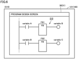
- step S10 the information processing device 100 receives an activation instruction to activate the development support program 110A (see Fig. 5 ). Upon receipt of the activation instruction, the information processing device 100 activates a development tool 30 as illustrated in Fig. 6.
- Fig. 6 is a diagram illustrating a program design screen 31 provided by the development tool 30. The program design screen 31 is displayed, for example, on the display unit 121 of the information processing device 100.
- the user program 210 may be described in any programming language.
- the user program 210 may be described in a ladder diagram (LD), or may be described in an instruction list (IL), a structured text (ST), or a sequential function chart (SFC), or a combination thereof.
- the user program 210 may be described in a general-purpose programming language such as JavaScript (registered trademark) or C language.
- the user program 210 is described in a ladder diagram.
- a designer may design the user program 210 suitable for controlling a target drive apparatus 300 by combining any function blocks or specifying input/output relationships of variables and function blocks.
- Each function block is a component integrated with functions repeatedly used in the user program 210.
- the user program 210 includes variables A to C and function blocks FB1 and FB2.
- the function block FB1 executes a predetermined function defined in the function block FB1 based on the value of the variable A associated with an input of the function block FB1.
- the execution result is reflected in the variable B associated with an output of the function block FB1.
- the function block FB2 executes a predetermined function defined in the function block FB2 based on the value of the variable B associated with an input of the function block FB2.
- the execution result is reflected in the variable C associated with an output of the function block FB2.
- the designer may design an arbitrary user program 210 by combining the variables and the function blocks on the program design screen 31.
- the user program 210 may include a function block for adding data to the data base 430.
- the function block after receiving the collected data input from the controller 200, generates an SQL statement for adding the collected data to the data base 430, and causes the external apparatus 400 to execute the generated SQL statement.
- step S30 the development tool 30 receives a compilation instruction.
- the development tool 30 compiles the user program 210 designed on the program design screen 31.
- the development tool 30 receives a download instruction to download the compilation result.
- the development tool 30 transfers the compiled user program 210 to the controller 200.
- the controller 200 stores the received user program 210 in the storage device 208 (see Fig. 3 ).
- step S32 the controller 200 receives an execution instruction to execute the user program 210.
- the controller 200 starts executing the user program 210.
- the controller 200 repeatedly executes a group of instructions included in the user program 210 at predetermined control cycles. More specifically, the controller 200 executes the first line to the last line of the user program 210 in one control cycle. In the next control cycle, the controller 200 executes the first line to the last line of the user program 210 again.
- the controller 200 generates a command value in each control cycle, and outputs the command value to the drive apparatus 300.
- step S50 the controller 200 determines whether or not an execution instruction to execute a process of generating a command value specified in the user program 210 is received.
- the execution instruction is issued in response to an input signal from an input device (such as a sensor or the like). If the controller 200 determines that the execution instruction is received (YES in step S50), the controller 200 generates the command value in accordance with the execution instruction, and sends the command value to the drive apparatus 300 (step S52). The drive apparatus 300 transports the control target in accordance with the command value received from the controller 200. If the controller 200 determines that an execution instruction to execute the process of generating a command value is not received (NO in step S50), the controller 200 proceeds the procedure to step S60 without executing step S52.
- step S60 the controller 200 determines whether or not an execution instruction to execute a process of uploading the collected data is received. If the controller 200 determines that the execution instruction is received (YES in step S60), the controller 200 generates an SQL statement for executing an insertion instruction.
- the SQL statement defines information (for example, a table name) which defines a destination table to which the data is inserted, the value of the data to be uploaded to each field or the like. If the controller 200 determines that the execution instruction is not received (NO in step S60), the controller 200 proceeds the procedure to step S70 without executing step S62.
- the controller 200 converts the type of each data to be collected, which is defined by the user program 210, into a data type of the data base 430.
- the type conversion is performed, for example, based on the configuration information 212 illustrated in Fig. 7.
- Fig. 7 is a diagram illustrating an example configuration information 212.
- the configuration information 212 is predefined by the user, for example.
- a correspondence relationship between the data type of the user program 210 and the data type of the data base 430 is defined for each table included in the data base 430.
- step S62 the controller 200 sends the SQL statement generated on the basis of the configuration information 212 to the external apparatus 400.
- the external apparatus 400 generates a record reflecting the variable value in each field in accordance with the SQL statement received from the controller 200, and adds the generated record to the corresponding table 432 in the data base 430. Thus, the collected data is reflected in the data base 430. Thereafter, the external apparatus 400 sends to the controller 200 an upload result indicating whether the execution of the SQL statement is successful or unsuccessful.
- step S64 the controller 200 associates the upload result received from the external apparatus 400 with the executed SQL statement, and writes both to the log data 214. If the upload result indicates that the upload is unsuccessful, the upload result is written to the log data 214 as an error log 215. On the other hand, if the upload result indicates that the upload is successful, the upload result is written to the log data 214 as a success log 216.
- step S70 the controller 200 determines whether or not to end the user program 210.
- An end instruction is issued, for example, upon receipt of an end operation from the user. If the controller 200 determines that an end operation is received from the user (YES in step S70), the controller 200 ends the user program 210. Otherwise (NO in step S70), the controller 200 returns the procedure to step S50.
- an SQL statement of an insertion instruction is sent from the controller 200 to the data base 430 on the external apparatus 400 in step S62, and however, it is acceptable that only a value to be inserted is sent the data base 430 on the external apparatus 400 in step S62.
- the external apparatus 400 generates an SQL statement of an insertion instruction upon receipt of the value to be inserted, and executes a process to insert the received value in accordance with the SQL statement.
- Fig. 8 is a diagram illustrating a sequence flow between the information processing device 100, the controller 200, the drive apparatus 300, and the external apparatus 400 during debug operation.
- step S80 the information processing device 100 receives an acquisition instruction to acquire the log data 214 (see Fig. 1 ).
- the acquisition instruction is received by the development tool 30, for example.
- the information processing device 100 sends an acquisition request to acquire the log data 214 to the controller 200 upon receipt of the acquisition instruction to acquire the log data 214.
- the controller 200 Upon receipt of the acquisition request, the controller 200 sends the log data 214 stored in the storage device 208 (see Fig. 3 ) to the information processing device 100.
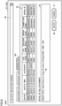
- step S82 the information processing device 100, upon receipt of the log data 214 from the controller 200, displays on the display unit 121 of the information processing device 100 a selection screen 40 illustrated in Fig. 9.
- Fig. 9 is a diagram illustrating a selection screen 40 for selecting an error log.
- the information processing device 100 displays the error logs included in the log data 214 as a log list 41.
- a log list 41 an entry, date and time where an error occurs, an error category, a log code, a log name, an execution result of SQL statement, an error code, a connection name to a data base, and a serial ID are displayed side by side.
- the user may select one of the error logs displayed in the log list 41.
- the error log may be selected by using, for example, the operation unit 115 of the information processing device 100.
- the SQL statement 52 corresponding to the selected error log is displayed in the detail display field 45.
- the enter button 46 is pressed after the selection of the error log, the selection of the error log is accepted.
- the cancel button 47 is pressed, the selection of the error log is canceled, and the selection screen 40 is closed.
- step S82 after the error log is selected, the enter button 46 is pressed. Accordingly, in step S84, the information processing device 100 displays on the display unit 121 an edit screen for editing the SQL statement.
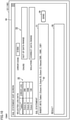
- Fig. 10 is a diagram illustrating an edit screen 50 in step S84.
- the edit screen 50 includes an SQL statement edit field 51, an error detail display field 53, a record information display field 55, a send button 56, and a result display field 58.
- the detailed information of the selected error log is displayed in the error detail display field 53.
- the detailed information displayed in the error detail display field 53 includes an error code, the cause of an error, and a solution to the error.
- the cause of an error and the solution to the error are stored in advance for each error code in the storage device 110 or the like of the information processing device 100.
- the information processing device 100 displays the cause of an error and the solution to the error corresponding to each error code of the selected error log in the error detail display field 53.
- the details of the data which is unsuccessfully inserted by the SQL statement 52 are displayed.
- the contents displayed in the record information display field 55 include the name of a destination table to which the data is inserted, the name of each field in the table, and the value of the unsuccessfully inserted data.
- the operation unit 115 of the information processing device 100 accepts an edit operation to edit the SQL statement 52 displayed in the edit field 51.
- the edit operation the table name is corrected, or the field name is edited, or the value is edited.
- these edit operations may also be performed on the record information display field 55.
- the edit operation performed on one of the edit field 51 and the record information display field 55 is reflected on the other, whereby the display contents of the edit field 51 and the display contents of the record information display field 55 are synchronized with each other.
- Fig. 11 is a diagram illustrating the edit screen 50 in step S86. As illustrated in Fig. 11 , in step S86, the value of column A of the SQL statement 52 is corrected from "200" to "90".
- step S90 the execution operation of the edited SQL statement 52 is accepted.
- the execution operation is accepted by the operation unit 115, for example.
- the information processing device 100 sends the corrected SQL statement 52 and an execution instruction to execute the corrected SQL statement 52 to the controller 200.
- the controller 200 Upon receipt of the corrected SQL statement 52 and the execution instruction from the information processing device 100, the controller 200 causes the external apparatus 400 to execute the corrected SQL statement 52.
- the external apparatus 400 upon receipt of the execution instruction to execute the corrected SQL statement 52 from the controller 200, executes the corrected SQL statement 52, and inserts data into the data base 430. Thereafter, the external apparatus 400 sends the execution result of the corrected SQL statement 52 to the controller 200.
- the controller 200 sends the execution result received from the external apparatus 400 to the information processing device 100.
- step S92 the information processing device 100 displays on the edit screen 50 the execution result received from the controller 200.
- Fig. 12 is a diagram illustrating the edit screen 50 in step S90. As illustrated in Fig. 12 , the execution result received from the controller 200 is displayed in the result display field 58 of the edit screen 50. "0 ⁇ 0000" illustrated in Fig. 12 indicates that the execution result is successful.
- a success log may be selected from the selection screen 40.
- the selection of a success log will be described with reference to Figs. 13 and 14 .
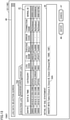
- Fig. 13 is a diagram illustrating a success log selection screen 40. As illustrated in Fig. 13 , when a tab TB2 on the selection screen 40 is pressed, the information processing device 100 displays success logs included in the log data 214 as the log list 41. The user may select one of the success logs displayed in the log list 41. The success log may be selected by using, for example, the operation unit 115 of the information processing device 100.
- an SQL statement 52A corresponding to the selected success log is displayed in the detail display field 45.
- the enter button 46 is pressed after the selection of the success log, the selection of the success log is accepted.
- the cancel button 47 is pressed, the selection of the success log is canceled, and the selection screen 40 is closed.
- Fig. 14 is a diagram illustrating an edit screen 50 for editing the selected SQL statement 52A.
- the SQL statement 52A corresponding to the selected success log is displayed in the edit field 51.
- the details of the data successfully inserted by the SQL statement 52A are displayed in the record information display field 55.
- the contents displayed in the record information display field 55 include the name of a destination table to which the data is inserted, the name of each field in the table, and the value of the successfully inserted data. In this way, the content of the selected success log is displayed, whereby the user may use the successfully executed SQL statement as a reference.
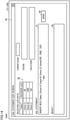
- Fig. 15 is a diagram illustrating an edit screen 50A according to a modification.
- the selected error log is displayed on the edit screen 50.
- the selected success log and the selected error log are displayed side by side on the edit screen 50A.
- the edit screen 50A includes an SQL statement edit field 51, a record information display field 55A, a send button 56, and a result display field 58.
- the edit screen 50A according to the present modification is different from the edit screen 50 in that the record information display field 55A is different from the record information display field 55.
- the others are the same as those described with reference to Fig. 10 , and the description thereof will not be repeated.
- the user may select, from the SQL statements included in the log data 214, not only an SQL statement which has an unsuccessful execution result but also an SQL statement which has a successful execution result.
- An error log and a success log may be selected by using the operation unit 115, for example.
- the information processing device 100 displays a data group 57A inserted by an SQL statement to be corrected which has an unsuccessful execution result and a data group 57B inserted by an SQL statement to be compared which has a successful execution result side by side.
- the user may compare the data group 57A which has an unsuccessful execution result with the data group 57B which has a successful execution result, and may easily determine the data with an abnormal value.
- the user may modify the data insertion location in the user program 210, the configuration information 212 (see Fig. 7 ) or the like.
- the information processing device 100 displays a set of data satisfying a predetermined comparison condition among the entire data set composed of the data included in the data group 57A which has an unsuccessful execution result and the data included in the data group 57B which has a successful execution result in a display mode different from the other data in the data set.
- the pair of data in column A is highlighted as compared with the pair of data in column B and the pair of data in column C.
- the highlighting may be realized by, for example, hatching, displaying in a specific color (for example, red), or blinking. Thereby, it is possible to easily recognize the data whose value is abnormal.
- the comparison condition is satisfied when the pair of data composed of one data included in the data group 57A and the other data included in the data group 57B matches a predetermined rule.
- the comparison condition is satisfied when one data is greater than or equal to a predetermined value (such as 100) and the other data is less than the predetermined value (such as 100).
- the comparison condition is satisfied when the number of digits is different between two data in the pair of data.
- the comparison condition may be set by the user in advance or may be set at the time of design.
- Fig. 16 is a diagram illustrating a selection screen 40A according to a modification.
- the selection screen 40A has a function of filtering the success logs to be displayed, and may extract a success log highly related to the SQL statement to be corrected. Thus, the user may easily select a success log for comparison.
- the selection screen 40A includes a log list 41, a filtering condition input field 44, a detail display field 45, an enter button 46, and a cancel button 47.
- the selection screen 40A illustrated in Fig. 16 is different from the selection screen 40 illustrated in Fig. 13 in that the selection screen 40A further includes a filtering condition input field 44.
- the others are the same as those described with reference to Fig. 13 , and the description thereof will not be repeated.
- the information processing device 100 displays on the display unit 121 an SQL statement, which is among the successful SQL statements included in the log data 214 and matches a part of the SQL statement to be corrected as a candidate for the SQL statement to be compared.
- the term of "matching" means that at least a predetermined number of words (for example, 1 to 4 words) in the SQL statement to be corrected are identical to those in the SQL statement to be compared. In this way, only the SQL statements similar to the SQL statement to be corrected are narrowed as the candidates for the SQL statement to be compared, which makes it possible to extract a success log highly related to the SQL statement to be corrected.
- the condition of narrowing the SQL statements for comparison is input in the filtering condition input field 44.
- the filtering condition input field 44 has check boxes 44A and 44B, for example.
- the information processing device 100 selects, from the SQL statements included in the log data 214, an SQL statement that matches the table name defined in the SQL statement to be corrected, and displays a success log corresponding to each selected SQL statement in the log list 41.
- the success log corresponding to an SQL statement which does not match the table name defined in the SQL statement to be corrected is not displayed in the log list 41.
- the user may reduce the number of logs to be displayed based on the table name.
- the information processing device 100 selects, from the SQL statements included in the log data 214, an SQL statement that matches the instruction sentence defined in the SQL statement to be corrected, and displays a success log corresponding to each selected SQL statement in the log list 41.
- the success log corresponding to an SQL statement which does not match the instruction sentence defined in the SQL statement to be corrected is not displayed in the log list 41.
- the user may reduce the number of logs to be displayed based on the instruction type.
- Fig. 17 is a flowchart illustrating a part of a process to be executed by the information processing device 100.
- the process illustrated in Fig. 17 is realized by a program to be executed by the processor 102 of the information processing device 100.
- a part of or the entire part of the process may be executed by circuit elements or other hardware.
- step S110 the processor 102 determines whether or not the instruction to be executed is an insertion instruction to insert data into the data base 430.
- the processor 102 determines that the instruction to be executed is an insertion instruction to insert data into the data base 430 (YES in step S110)
- the processor 102 proceeds the process to step S114. Otherwise (NO in step S110), the processor 102 proceeds the process to step S112.
- step S112 the processor 102 executes the instruction.
- step S114 the processor 102 converts the type of data to be collected into the type of data on the data base 430 based on the configuration information 212 (see Fig. 7 ), and generates an SQL statement for data insertion. Then, the processor 102 sends the execution instruction of the SQL statement together with the generated SQL statement to the external apparatus 400. In response, the external apparatus 400 executes a data insertion process so as to insert data into the data base 430, and sends the execution result to the controller 200.
- step S116 the processor 102 receives, from the external apparatus 400, the execution result of the SQL statement generated in step S114.
- step S120 the processor 102 determines whether or not the execution result received from the external apparatus 400 is successful.
- the processor 102 determines that the execution result received from the external apparatus 400 is successful (YES in step S120)
- the processor 102 proceeds the process to step S140. Otherwise (NO in step S120), the processor 102 proceeds the process to step S130.
- step S130 the processor 102 determines whether or not the storage of logs in the error log 215 (see Fig. 3 ) is enabled.
- the storage of logs in the error log 215 is enabled or disabled in advance.
- the processor 102 determines that the storage of logs in the error log 215 is enabled (YES in step S130)
- the processor 102 proceeds the process to step S132. Otherwise (NO in step S130), the processor 102 proceeds the process to step S150.
- step S132 the processor 102 writes the execution result received in step S116 into the error log 215.
- step S140 the processor 102 determines whether or not the storage of logs in the success log 216 (see Fig. 3 ) is enabled.
- the storage of logs in the success log 216 is enabled or disabled in advance.
- the processor 102 determines that the storage of logs in the success log 216 is enabled (YES in step S140)
- the processor 102 proceeds the process to step S142. Otherwise (NO in step S140), the processor 102 proceeds the process to step S150.
- step S142 the processor 102 writes the execution result received in step S116 into the success log 216.
- step S150 the processor 102 determines whether or not the executed insertion process is a test execution. For example, if the insertion process is executed by pressing the send button 56 on the edit screen 50 (see Fig. 10 ), the processor 102 determines that the executed insertion process is a test execution. When the processor 102 determines that the executed insertion process is a test execution (YES in step S150), the processor 102 proceeds the process to step S152. Otherwise (NO in step S150), the processor 102 proceeds the process to step S160.
- step S152 the processor 102 sends the execution result received in step S116 to the information processor 100.
- the execution result is displayed on the display unit 121 of the information processor 100.
- step S160 the processor 102 determines whether or not to terminate the program.
- the termination instruction is issued, for example, upon receipt of a termination operation from the user.
- the processor 102 determines to terminate the program (YES in step S160)
- the processor 102 ends the process illustrated in Fig. 17 . Otherwise (NO in step S160), the processor 102 returns the process to step S110.
- the present embodiment includes the following aspects.
- a control system comprising an information processing device (100) configured to communicate with a controller (200) configured to control a control target,
- the control system wherein the display control unit (154) is configured to display a set of data satisfying a predetermined comparison condition among the entire data set composed of data inserted into the data base (430) by the SQL statement to be corrected and data inserted into the data base (430) by the SQL statement to be compared in a display mode different from the other data in the data set.
- the control system according to configuration 5, wherein the display control unit (154) is configured to display on the display unit (121) an SQL statement among the SQL statements included in the log data that matches a table name defined in the SQL statement to be corrected as the candidate.
Landscapes
- Engineering & Computer Science (AREA)
- Theoretical Computer Science (AREA)
- Physics & Mathematics (AREA)
- Databases & Information Systems (AREA)
- General Engineering & Computer Science (AREA)
- General Physics & Mathematics (AREA)
- Data Mining & Analysis (AREA)
- Computational Linguistics (AREA)
- Mathematical Physics (AREA)
- Quality & Reliability (AREA)
- Health & Medical Sciences (AREA)
- Biomedical Technology (AREA)
- Computer Hardware Design (AREA)
- Software Systems (AREA)
- Automation & Control Theory (AREA)
- Programmable Controllers (AREA)
- Debugging And Monitoring (AREA)
Abstract
Description
- The present disclosure relates to a technique for generating tables on a data base to be accessed by a controller.
- FA (Factory Automation) systems for automating production processes have become widespread in various production sites. The FA system includes an input apparatus, a drive apparatus, a controller, and the like. The controller controls the drive apparatus in accordance with inputs from various sensors as input devices. The drive apparatus includes, for example, a transporting plate for transporting a workpiece, a conveyor for conveying a workpiece, and an arm robot for transporting a workpiece to a predetermined target location.
- In recent years, controllers capable of accessing a data base on an external apparatus have become widespread. As such a controller,
Japanese Patent Laid-Open No. 2016-194808 WO2014/184962 (PTL 2) discloses a controller capable of reducing the number of steps of reading data from a data base as compared with a conventional method. -
- PTL 1:
Japanese Patent Laid-Open No. 2016-194808 - PTL 2:
WO2014/184962 - Data related to a control target such as a drive apparatus is collected by a controller, and the collected data is sequentially added to the data base. At this time, the collected data may not be properly added to the data base due to some kinds of errors. In this case, the user needs to determine the cause of error and correct the SQL statement, the configuration or the like. The error may be caused by various factors, and depending on the type of errors, it is very difficult to determine the cause thereof. Accordingly, such a technique is desired that assists users in determining the cause of an error that occurs during the addition of collected data to a data base.
- An embodiment of the present disclosure provides an information processing device configured to communicate with a controller configured to a control target. Any of the controller and the information processing device includes a storage device configured to store one or more SQL statements to be executed so as to insert data related to the control target into a data base and an execution result of each of the one or more SQL statements in association with each other as log data. The information processing device includes a display unit, a display control unit configured to display on the display unit an SQL statement to be corrected which is among the SQL statements included in the log data and has an unsuccessful execution result, an operation unit configured to accept a correction operation on the SQL statement to be corrected and an execution operation on the corrected SQL statement, and a communication unit configured to send an execution instruction to execute the corrected SQL statement to the controller upon receipt of the execution operation by the operation unit and to receive an execution result of the corrected SQL statement from the controller. The display control unit displays an execution result of the corrected SQL statement on the display unit.
- According to an aspect of the present disclosure, the operation unit is further configured to accept an operation of selecting, from the SQL statements included in the log data, an SQL statement to be compared which has a successful execution result, and the display control unit displays the data inserted into the data base by the SQL statement to be corrected and the data inserted into the data base by the SQL statement to be compared side by side.
- According to an aspect of the present disclosure, the display control unit displays a set of data satisfying a predetermined comparison condition among the entire data set composed of data inserted into the data base by the SQL statement to be corrected and data inserted into the data base by the SQL statement to be compared in a display mode different from the other data in the data set.
- According to an aspect of the present disclosure, the predetermined comparison condition is satisfied when the number of digits is different between the data in the data set.
- According to an aspect of the present disclosure, the display control unit displays on the display unit an SQL statement among the SQL statements included in the log data that matches a part of the SQL statement to be corrected as a candidate of the SQL statement to be compared, and the operation unit accepts a selection operation of selecting the SQL statement to be compared from the candidates.
- According to an aspect of the present disclosure, the display control unit displays on the display unit an SQL statement among the SQL statements included in the log data that matches a table name defined in the SQL statement to be corrected as the candidate.
- Another embodiment of the present disclosure provides a control method of an information processing device configured to communicate with a controller that controls a control target. Any of the controller and the information processing device includes a storage device configured to store one or more SQL statements to be executed so as to insert data related to the control target into a data base and an execution result of each of the one or more SQL statements in association with each other as log data. The control method includes: displaying on the display unit an SQL statement to be corrected which is among the SQL statements included in the log data and has an unsuccessful execution result; accepting a correction operation on the SQL statement to be corrected and an execution operation on the corrected SQL statement; sending an execution instruction to execute the corrected SQL statement to the controller upon receipt of the execution operation and receiving from the controller an execution result of the corrected SQL statement; and displaying an execution result of the corrected SQL statement on the display unit.
- Another embodiment of the present disclosure provides a control program for an information processing device configured to communicate with a controller that controls a control target. Any of the controller and the information processing device includes a storage device configured to store one or more SQL statements to be executed so as to insert data related to the control target into a data base and an execution result of each of the one or more SQL statements in association with each other as log data. The control program causes the information processing device to perform: displaying on the display unit an SQL statement to be corrected which is among the SQL statements included in the log data and has an unsuccessful execution result; accepting a correction operation on the SQL statement to be corrected and an execution operation on the corrected SQL statement; sending an execution instruction to execute the corrected SQL statement to the controller upon receipt of the execution operation and receiving from the controller an execution result of the corrected SQL statement; and displaying an execution result of the corrected SQL statement on the display unit.
-
-
Fig. 1 is a diagram illustrating an example configuration of a control system according to an embodiment; -
Fig. 2 is a schematic diagram illustrating a hardware configuration of an information processing device according to an embodiment; -
Fig. 3 is a schematic diagram illustrating a hardware configuration of a controller according to an embodiment; -
Fig. 4 is a block diagram illustrating a hardware configuration of an external apparatus according to the embodiment; -
Fig. 5 is a diagram illustrating a sequence flow between an information processing device, a controller, a drive apparatus, and an external apparatus during normal operation; -
Fig. 6 is a diagram illustrating a program design screen provided by a development tool; -
Fig. 7 is a diagram illustrating an example of configuration information; -
Fig. 8 is a diagram illustrating a sequence flow between an information processing device, a controller, a drive apparatus, and an external apparatus during debug operation; -
Fig. 9 is a diagram illustrating an error log selection screen; -
Fig. 10 is a diagram illustrating an edit screen in step S84 illustrated inFig. 8 ; -
Fig. 11 is a diagram illustrating an edit screen in step S86 illustrated inFig. 8 ; -
Fig. 12 is a diagram illustrating an edit screen in step S90 illustrated inFig. 8 ; -
Fig. 13 is a diagram illustrating a success log selection screen; -
Fig. 14 is a diagram illustrating an edit screen for a selected SQL statement; -
Fig. 15 is a diagram illustrating an edit screen according to a modification; -
Fig. 16 is a diagram illustrating a selection screen according to a modification; and -
Fig. 17 is a flowchart illustrating a part of a process to be executed by the information processing device according to an embodiment. - Hereinafter, embodiments according to the present disclosure will be described with reference to the drawings. In the following description, the same parts or components are denoted by the same reference numerals, and have the same names and functions. Therefore, the detailed description thereof will not be repeated.
- An application example of the present disclosure will be described with reference to
Fig. 1. Fig. 1 is a diagram illustrating an example configuration of acontrol system 10 according to an embodiment. - The
control system 10 is an FA (Factory Automation) system for automating a production process. In the example ofFig. 1 , thecontrol system 10 includes one or moreinformation processing devices 100, one ormore controllers 200, one ormore drive apparatuses 300, and one or moreexternal apparatuses 400. - The
information processing device 100, thecontroller 200, and theexternal apparatus 400 are connected to a network NW1. The network NW1 may be an EtherNET, an OPC-UA (Object Linking and Embedding for Process Control Unified Architecture), or the like. The OPC-UA is a communication standard for realizing data exchange without depending on the type of vendor or OS (Operating System). - The
controller 200 and thedrive apparatus 300 are connected to a network NW2. The network NW2 is preferably a field network that performs constant-period communication to guarantee the arrival time of data. The field network that performs constant-period communication is known as an EtherCAT (registered trademark), an EtherNet/IP (registered trademark), a CompoNet (registered trademark), or the like. - The
information processing device 100 may be, for example, a notebook PC (Personal Computer) or a desktop PC, a tablet terminal, a smartphone, or the other information processing terminal. The hardware configuration of theinformation processing device 100 includes aprocessor 102, anoperation unit 115, and adisplay unit 121. - The
controller 200 may be, for example, a PLC (Programmable Logic Controller). Thecontroller 200 controls thedrive apparatus 300 in accordance with a pre-determined user program. Thedrive apparatus 300 includes various industrial apparatuses for automating a production process. As an example, thedrive apparatus 300 may be a robot controller, a servo driver, an arm robot controlled by the robot controller, a servo motor controlled by the servo driver, or the like. Further, thedrive apparatus 300 may be a visual sensor which photographs a workpiece, any other devices used in a production process, or the like. - During the execution of a user program, the
controller 200 collects various kinds of data indicating the state of thedrive apparatus 300 to be controlled, and periodically adds the collected data to adata base 430 on theexternal apparatus 400. Alternatively, the collected data may be added to thedata base 430 at a predetermined time when a control input is made or when the execution is completed. Thedata base 430 on theexternal apparatus 400 is constituted by one or more tables 432 generated in advance. The table 432 includes vertical fields as columns and horizontal fields as records. The collected data is added to the table 432 defined by the SQL statement. - The
controller 200 stores the result of adding the collected data to thedata base 430 in thestorage device 208 aslog data 214. In thelog data 214, each SQL statement executed so as to add the collected data into thedata base 430 is associated with the execution result of each SQL statement. For example, if a SQL statement is successfully executed, a symbol "OK" indicating that the execution result is successful is written to thelog data 214 together with the executed SQL statement. On the other hand, if the SQL statement is not successfully executed, a symbol "NG" indicating that the execution result is unsuccessful is written to thelog data 214 together with the executed SQL statement. Preferably, an error code is further written to thelog data 214. The error code includes, for example, an error code indicating a connection error, an error code indicating that the right side of a character string is discarded, an error code indicating that the data is out of a data range, an error code indicating that the format of date and time is invalid, or the like. - When an error occurs in the
log data 214, the user needs to determine the cause of the error so as to correct the SQL statement, the configuration or the like. Errors may be caused by various factors, and depending on the types of errors, it is very difficult to determine the cause of an error. Theinformation processing device 100 assists the user in determining the cause of an error that occurs during the addition of the collected data to thedata base 430. As a functional configuration constituting the information processing device, theprocessor 102 provides acommunication unit 152 and adisplay control unit 154. - The
communication unit 152 is implemented by a communication driver that establishes communication with thecontroller 200. Thecommunication unit 152 receives thelog data 214 from thecontroller 200, and outputs the receivedlog data 214 to thedisplay control unit 154. - The
display control unit 154 is a functional module that controls the contents to be displayed on thedisplay unit 121. In the example ofFig. 1 , thedisplay control unit 154 displays on thedisplay unit 121 anedit screen 50 for editing an SQL statement. - The
edit screen 50 includes an SQLstatement edit field 51, a recordinformation display field 55, asend button 56, and aresult display field 58. - The
display control unit 154 displays in theedit field 51 anSQL statement 52 which is among the SQL statements included in thelog data 214 and has an unsuccessful execution result. Further, thedisplay control unit 154 displays in the recordinformation display field 55 the details of data unsuccessfully inserted by theSQL statement 52. The contents displayed in the recordinformation display field 55 include the name of a table for the data insertion, the name of each field in the table, and the value of the unsuccessfully inserted data. - The
operation unit 115 accepts various user operations on theinformation processing device 100. As an example, theoperation unit 115 accepts a correction operation to correct theSQL statement 52 displayed in theedit field 51. Theoperation unit 115 accepts an execution operation to execute the correctedSQL statement 52. The execution operation is accepted, for example, when thesend button 56 on theedit screen 50 is pressed. - The
communication unit 152 sends the correctedSQL statement 52 and an execution instruction to execute the correctedSQL statement 52 to thecontroller 200 after theoperation unit 115 accepts an execution operation. Thecontroller 200 causes theexternal apparatus 400 to execute the correctedSQL statement 52 upon receipt of the correctedSQL statement 52 and the execution instruction from theinformation processing device 100. Thereafter, thecontroller 200 sends the execution result of the correctedSQL statement 52 to theinformation processing device 100. Thecommunication unit 152 of theinformation processing device 100 outputs the execution result to thedisplay control unit 154 upon receipt of the execution result from thecontroller 200. Then, thedisplay control unit 154 displays on thedisplay unit 121 the execution result received from thecommunication unit 152. In the example ofFig. 1 , the execution result of the correctedSQL statement 52 is displayed in the executionresult display field 58 on theedit screen 50. - As described in the above, the
information processing device 100 displays on thedisplay unit 121 theSQL statement 52 to be corrected which is among the SQL statements included in thelog data 214 and has an unsuccessful execution result. Then, theinformation processing device 100 accepts a correction operation to correct the displayedSQL statement 52 and an execution operation to execute a test on the correctedSQL statement 52. By providing such a debug environment, the user may easily determine the cause of an error that occurs during the addition of the collected data to a data base, and may correct the SQL statement or the configuration in accordance with the determined cause. - Although in the example of
Fig. 1 , it is described that thedata base 430 is provided on theexternal apparatus 400, it is not necessary that thedata base 430 is provided on theexternal apparatus 400. For example, thedata base 430 may be provided on thecontroller 200. Alternatively, thedata base 430 may be provided on a separate unit connected to thecontroller 200 via an internal bus. - The writing function to the data base and the log storing function may be implemented on an unit attached to the
controller 200. Thelog data 214 may be stored in theinformation processing device 100 instead of thecontroller 200. - The hardware configuration of the
information processing device 100, the hardware configuration of thecontroller 200, and the hardware configuration of theexternal apparatus 400 will be described in order with reference toFigs. 2 to 4 . - First, the hardware configuration of the
information processing device 100 will be described with reference toFig. 2. Fig. 2 is a schematic diagram illustrating a hardware configuration of theinformation processing device 100. - The
information processing device 100 is, for example, a computer constructed according to a general-purpose computer architecture. Theinformation processing device 100 includes aprocessor 102 such as a CPU (Central Processing Unit) or an MPU (Micro-Processing Unit), amain memory 104, anonvolatile storage device 110, acommunication interface 111, an I/O (Input/Output)interface 114, and adisplay interface 120. These components are communicatively connected to each other via aninternal bus 125. - The
processor 102 controls the operation of theinformation processing device 100 by executing various control programs such as adevelopment support program 110A. Thedevelopment support program 110A is such a program that provides an environment for developing a control program (user program) of thecontroller 200. Upon receipt of an execution instruction to execute various control programs such as thedevelopment support program 110A, theprocessor 102 reads out a target control program from thestorage device 110 into themain memory 104. - The
communication interface 111 exchanges data with the other communication devices via network. The other communication devices include, for example, acontroller 200, anexternal apparatus 400, and a server. Theinformation processing device 100 may be configured to download various control programs such as thedevelopment support program 110A from the other communication device via thecommunication interface 111. - The I/
O interface 114 is connected to theoperation unit 115, and is configured to receive from the operation unit 115 a signal indicating a user operation. Theoperation unit 115 typically includes a keyboard, a mouse, a touch panel, a touch pad or the like, and accepts operations from a user. In the example ofFig. 2 , theinformation processing device 100 and theoperation unit 115 are illustrated as separate units, but theinformation processing device 100 and theoperation unit 115 may be constructed as an integral unit. - The
display interface 120 is connected to thedisplay unit 121, and is configured to send to thedisplay unit 121 an image signal for displaying an image in accordance with an instruction from theprocessor 102 or the like. Thedisplay unit 121 may be, for example, an LCD (Liquid Crystal Display) or an organic EL (Electro Luminescence) display, and is configured to present various kinds of information to the user. Thedisplay unit 121 may display various screens provided by thedevelopment support program 110A. In the example ofFig. 2 , theinformation processing device 100 and thedisplay unit 121 are illustrated as separate units, but theinformation processor 100 and thedisplay unit 121 may be constructed as an integral unit. - Next, the hardware configuration of the
controller 200 will be described with reference toFig. 3. Fig. 3 is a schematic diagram illustrating a hardware configuration of thecontroller 200. - The
controller 200 includes acommunication interface 201, aprocessor 202 such as a CPU or MPU, achipset 204, amain memory 206, anonvolatile storage device 208, aninternal bus controller 222, afield bus controller 224, and amemory card interface 239. - The
processor 202 controlsvarious drive apparatuses 300 by reading out thecontrol program 211 stored in thestorage device 208, developing thecontrol program 211 in themain memory 206, and executing thecontrol program 211. Thecontrol program 211 includes various programs for controlling thecontroller 200. As an example, thecontrol program 211 includes asystem program 209, auser program 210 or the like. Thesystem program 209 includes instruction codes for providing basic functions of thecontroller 200 such as data input/output processing or execution timing control. Theuser program 210 is downloaded from theinformation processing device 100. Theuser program 210 may be configured arbitrarily according to a control target, and includes asequence program 210A for executing a sequence control and amotion program 210B for executing a motion control. - The
chipset 204 controls each component so as to realize the overall processing of thecontroller 200. - The
storage device 208 stores thecontrol program 211 and various data. As an example, thestorage device 208stores configuration information 212 which defines a correspondence relationship between a data type on theuser program 210 and a data type on thedata base 430, and the log data 214 (seeFig. 1 ). The detail of theconfiguration information 212 will be described later. Thelog data 214 includes anerror log 215 and asuccess log 216. - The
internal bus controller 222 is an interface that exchanges data with various devices connected to thecontroller 200 via an internal bus. As an example of such a device, an I/O unit 226 connected to thecontroller 200 may be given. - The
field bus controller 224 is an interface that exchanges data withvarious drive apparatuses 300 connected to thecontroller 200 via a field bus. As an example of such a device, aservo driver 300A and aservo driver 300B connected to thecontroller 200 may be given. In addition, a drive apparatus such as a robot controller or a visual sensor may be connected to thecontroller 200. - The
internal bus controller 222 and thefield bus controller 224 may provide arbitrary instructions to any device connected thereto, and may acquire arbitrary data managed by any device connected thereto. Theinternal bus controller 222 and/or thefield bus controller 224 also functions as an interface for exchanging data with a robot controller or a servo driver. - The
communication interface 201 controls the data exchange via various wired/wireless networks. Thecontroller 200 communicates with theinformation processing device 100 and theexternal apparatus 400 via thecommunication interface 201. In addition, thecontroller 200 may access thedata base 430 on theexternal apparatus 400 via thecommunication interface 201. - The
memory card interface 239 is such an interface that permits an external storage medium such as a memory card 240 (for example, an SD card) to be attached thereto or detached therefrom, and permits data to be written to thememory card 240 and data to be read out from thememory card 240. - Next, the hardware configuration of the
external apparatus 400 will be described with reference toFig. 4. Fig. 4 is a block diagram illustrating a hardware configuration of theexternal apparatus 400. - The
external apparatus 400 is constructed according to a general-purpose hardware architecture. In other words, theexternal apparatus 400 is constructed as a personal computer. However, theexternal apparatus 400 may be constructed as dedicated hardware instead of general-purpose hardware. - More specifically, the
external apparatus 400 includes aprocessor 402 such as a CPU or MPU, amain memory 404, anonvolatile storage device 410, acommunication interface 412, an I/O interface 414, and adisplay interface 420. These components are communicatively connected to each other via aninternal bus 425. - The
processor 402 controls theexternal apparatus 400 by reading out a control program (not shown) stored in thestorage device 410, developing the control program in themain memory 404, and executing the control program. In other words, theprocessor 402 implements a control unit that performs control operation in cooperation with themain memory 404 and thestorage device 410. - The
communication interface 412, the I/O interface 414, and the field bus interface 416 mediate the exchange of data between theexternal apparatus 400 and the other communication devices. - More specifically, the
communication interface 412 mediates communications with thecontroller 200 via the network NW1 (seeFig. 1 ) or the like. Thecommunication interface 412 may be, for example, a component capable of communicating in accordance with EtherNET. - The I/
O interface 414 is connected to theoperation unit 415, and is configured to receive from the operation unit 415 a signal indicating a user operation. Theoperation unit 415 typically includes a keyboard, a mouse, a touch panel, a touch pad or the like, and accepts an operation from a user. In the example ofFig. 4 , theexternal apparatus 400 and theoperation unit 415 are illustrated as separate units, but theexternal apparatus 400 and theoperation unit 415 may be constructed as an integral unit. - The
display interface 420 is connected to thedisplay unit 421, and is configured to send to thedisplay unit 421 an image signal for displaying an image in accordance with an instruction from theprocessor 402 or the like. Thedisplay unit 421 may be an LCD, an organic EL display, or the like, and is configured to present various kinds of information to the user. In the example ofFig. 4 , theexternal apparatus 400 and thedisplay unit 421 are illustrated as separate units, but theexternal apparatus 400 and thedisplay unit 421 may be constructed as an integral unit. - A sequence flow during normal operation will be described with reference to
Figs. 5 and6 .Fig. 5 is a diagram illustrating a sequence flow between theinformation processing device 100, thecontroller 200, thedrive apparatus 300, and theexternal apparatus 400 during normal operation. - In step S10, the
information processing device 100 receives an activation instruction to activate thedevelopment support program 110A (seeFig. 5 ). Upon receipt of the activation instruction, theinformation processing device 100 activates adevelopment tool 30 as illustrated inFig. 6. Fig. 6 is a diagram illustrating aprogram design screen 31 provided by thedevelopment tool 30. Theprogram design screen 31 is displayed, for example, on thedisplay unit 121 of theinformation processing device 100. - The
user program 210 may be described in any programming language. For example, theuser program 210 may be described in a ladder diagram (LD), or may be described in an instruction list (IL), a structured text (ST), or a sequential function chart (SFC), or a combination thereof. Alternatively, theuser program 210 may be described in a general-purpose programming language such as JavaScript (registered trademark) or C language. - In the example of
Fig. 6 , theuser program 210 is described in a ladder diagram. On theprogram design screen 31, a designer may design theuser program 210 suitable for controlling atarget drive apparatus 300 by combining any function blocks or specifying input/output relationships of variables and function blocks. Each function block is a component integrated with functions repeatedly used in theuser program 210. - In the example of
Fig. 6 , theuser program 210 includes variables A to C and function blocks FB1 and FB2. The function block FB1 executes a predetermined function defined in the function block FB1 based on the value of the variable A associated with an input of the function block FB1. The execution result is reflected in the variable B associated with an output of the function block FB1. The function block FB2 executes a predetermined function defined in the function block FB2 based on the value of the variable B associated with an input of the function block FB2. The execution result is reflected in the variable C associated with an output of the function block FB2. Thus, the designer may design anarbitrary user program 210 by combining the variables and the function blocks on theprogram design screen 31. - In addition, the
user program 210 may include a function block for adding data to thedata base 430. The function block, after receiving the collected data input from thecontroller 200, generates an SQL statement for adding the collected data to thedata base 430, and causes theexternal apparatus 400 to execute the generated SQL statement. - With reference to
Fig. 5 again, in step S30, thedevelopment tool 30 receives a compilation instruction. Upon receipt of the compilation instruction, thedevelopment tool 30 compiles theuser program 210 designed on theprogram design screen 31. Thereafter, thedevelopment tool 30 receives a download instruction to download the compilation result. Upon receipt of the download instruction, thedevelopment tool 30 transfers the compileduser program 210 to thecontroller 200. Thecontroller 200 stores the receiveduser program 210 in the storage device 208 (seeFig. 3 ). - In step S32, the
controller 200 receives an execution instruction to execute theuser program 210. Upon receipt of the execution instruction, thecontroller 200 starts executing theuser program 210. When theuser program 210 is a cyclic executable program, thecontroller 200 repeatedly executes a group of instructions included in theuser program 210 at predetermined control cycles. More specifically, thecontroller 200 executes the first line to the last line of theuser program 210 in one control cycle. In the next control cycle, thecontroller 200 executes the first line to the last line of theuser program 210 again. Thecontroller 200 generates a command value in each control cycle, and outputs the command value to thedrive apparatus 300. - In step S50, the
controller 200 determines whether or not an execution instruction to execute a process of generating a command value specified in theuser program 210 is received. As an example, the execution instruction is issued in response to an input signal from an input device (such as a sensor or the like). If thecontroller 200 determines that the execution instruction is received (YES in step S50), thecontroller 200 generates the command value in accordance with the execution instruction, and sends the command value to the drive apparatus 300 (step S52). Thedrive apparatus 300 transports the control target in accordance with the command value received from thecontroller 200. If thecontroller 200 determines that an execution instruction to execute the process of generating a command value is not received (NO in step S50), thecontroller 200 proceeds the procedure to step S60 without executing step S52. - In step S60, the
controller 200 determines whether or not an execution instruction to execute a process of uploading the collected data is received. If thecontroller 200 determines that the execution instruction is received (YES in step S60), thecontroller 200 generates an SQL statement for executing an insertion instruction. The SQL statement defines information (for example, a table name) which defines a destination table to which the data is inserted, the value of the data to be uploaded to each field or the like. If thecontroller 200 determines that the execution instruction is not received (NO in step S60), thecontroller 200 proceeds the procedure to step S70 without executing step S62. - At the time of generating the SQL statement, the
controller 200 converts the type of each data to be collected, which is defined by theuser program 210, into a data type of thedata base 430. The type conversion is performed, for example, based on theconfiguration information 212 illustrated inFig. 7. Fig. 7 is a diagram illustrating anexample configuration information 212. Theconfiguration information 212 is predefined by the user, for example. As illustrated inFig. 7 , in theconfiguration information 212, a correspondence relationship between the data type of theuser program 210 and the data type of thedata base 430 is defined for each table included in thedata base 430. - In step S62, the
controller 200 sends the SQL statement generated on the basis of theconfiguration information 212 to theexternal apparatus 400. Theexternal apparatus 400 generates a record reflecting the variable value in each field in accordance with the SQL statement received from thecontroller 200, and adds the generated record to the corresponding table 432 in thedata base 430. Thus, the collected data is reflected in thedata base 430. Thereafter, theexternal apparatus 400 sends to thecontroller 200 an upload result indicating whether the execution of the SQL statement is successful or unsuccessful. - In step S64, the
controller 200 associates the upload result received from theexternal apparatus 400 with the executed SQL statement, and writes both to thelog data 214. If the upload result indicates that the upload is unsuccessful, the upload result is written to thelog data 214 as anerror log 215. On the other hand, if the upload result indicates that the upload is successful, the upload result is written to thelog data 214 as asuccess log 216. - In step S70, the
controller 200 determines whether or not to end theuser program 210. An end instruction is issued, for example, upon receipt of an end operation from the user. If thecontroller 200 determines that an end operation is received from the user (YES in step S70), thecontroller 200 ends theuser program 210. Otherwise (NO in step S70), thecontroller 200 returns the procedure to step S50. - In the above, it is described that an SQL statement of an insertion instruction is sent from the
controller 200 to thedata base 430 on theexternal apparatus 400 in step S62, and however, it is acceptable that only a value to be inserted is sent thedata base 430 on theexternal apparatus 400 in step S62. In this case, theexternal apparatus 400 generates an SQL statement of an insertion instruction upon receipt of the value to be inserted, and executes a process to insert the received value in accordance with the SQL statement. - A sequence flow during debug operation will be described with reference to
Figs. 8 to 11 .Fig. 8 is a diagram illustrating a sequence flow between theinformation processing device 100, thecontroller 200, thedrive apparatus 300, and theexternal apparatus 400 during debug operation. - In step S80, the
information processing device 100 receives an acquisition instruction to acquire the log data 214 (seeFig. 1 ). The acquisition instruction is received by thedevelopment tool 30, for example. Theinformation processing device 100 sends an acquisition request to acquire thelog data 214 to thecontroller 200 upon receipt of the acquisition instruction to acquire thelog data 214. Upon receipt of the acquisition request, thecontroller 200 sends thelog data 214 stored in the storage device 208 (seeFig. 3 ) to theinformation processing device 100. - In step S82, the
information processing device 100, upon receipt of thelog data 214 from thecontroller 200, displays on thedisplay unit 121 of the information processing device 100 aselection screen 40 illustrated inFig. 9. Fig. 9 is a diagram illustrating aselection screen 40 for selecting an error log. - As illustrated in
Fig. 9 , when a tab TB1 on theselection screen 40 is pressed, theinformation processing device 100 displays the error logs included in thelog data 214 as alog list 41. In thelog list 41, an entry, date and time where an error occurs, an error category, a log code, a log name, an execution result of SQL statement, an error code, a connection name to a data base, and a serial ID are displayed side by side. The user may select one of the error logs displayed in thelog list 41. The error log may be selected by using, for example, theoperation unit 115 of theinformation processing device 100. - In response to the selection of one error log from the
log list 41, theSQL statement 52 corresponding to the selected error log is displayed in thedetail display field 45. When theenter button 46 is pressed after the selection of the error log, the selection of the error log is accepted. On the other hand, when the cancelbutton 47 is pressed, the selection of the error log is canceled, and theselection screen 40 is closed. - In step S82, after the error log is selected, the
enter button 46 is pressed. Accordingly, in step S84, theinformation processing device 100 displays on thedisplay unit 121 an edit screen for editing the SQL statement. -
Fig. 10 is a diagram illustrating anedit screen 50 in step S84. Theedit screen 50 includes an SQLstatement edit field 51, an errordetail display field 53, a recordinformation display field 55, asend button 56, and aresult display field 58. - In the
edit field 51, anSQL statement 52 corresponding to the error log selected in step S82 is displayed. - The detailed information of the selected error log is displayed in the error
detail display field 53. The detailed information displayed in the errordetail display field 53 includes an error code, the cause of an error, and a solution to the error. The cause of an error and the solution to the error are stored in advance for each error code in thestorage device 110 or the like of theinformation processing device 100. Theinformation processing device 100 displays the cause of an error and the solution to the error corresponding to each error code of the selected error log in the errordetail display field 53. - In the record
information display field 55, the details of the data which is unsuccessfully inserted by theSQL statement 52 are displayed. The contents displayed in the recordinformation display field 55 include the name of a destination table to which the data is inserted, the name of each field in the table, and the value of the unsuccessfully inserted data. - The
operation unit 115 of theinformation processing device 100 accepts an edit operation to edit theSQL statement 52 displayed in theedit field 51. According to the edit operation, the table name is corrected, or the field name is edited, or the value is edited. Preferably, these edit operations may also be performed on the recordinformation display field 55. Thus, the edit operation performed on one of theedit field 51 and the recordinformation display field 55 is reflected on the other, whereby the display contents of theedit field 51 and the display contents of the recordinformation display field 55 are synchronized with each other. -
Fig. 11 is a diagram illustrating theedit screen 50 in step S86. As illustrated inFig. 11 , in step S86, the value of column A of theSQL statement 52 is corrected from "200" to "90". - If the
send button 56 of theedit screen 50 is pressed in step S90, the execution operation of the editedSQL statement 52 is accepted. The execution operation is accepted by theoperation unit 115, for example. Upon receipt of the execution operation by theoperation unit 115, theinformation processing device 100 sends the correctedSQL statement 52 and an execution instruction to execute the correctedSQL statement 52 to thecontroller 200. Upon receipt of the correctedSQL statement 52 and the execution instruction from theinformation processing device 100, thecontroller 200 causes theexternal apparatus 400 to execute the correctedSQL statement 52. - The
external apparatus 400, upon receipt of the execution instruction to execute the correctedSQL statement 52 from thecontroller 200, executes the correctedSQL statement 52, and inserts data into thedata base 430. Thereafter, theexternal apparatus 400 sends the execution result of the correctedSQL statement 52 to thecontroller 200. Thecontroller 200 sends the execution result received from theexternal apparatus 400 to theinformation processing device 100. - In step S92, the
information processing device 100 displays on theedit screen 50 the execution result received from thecontroller 200.Fig. 12 is a diagram illustrating theedit screen 50 in step S90. As illustrated inFig. 12 , the execution result received from thecontroller 200 is displayed in theresult display field 58 of theedit screen 50. "0×0000" illustrated inFig. 12 indicates that the execution result is successful. - In
Fig. 9 , it is described that an error log is selected from theselection screen 40, and however, a success log may be selected from theselection screen 40. Hereinafter, the selection of a success log will be described with reference toFigs. 13 and14 . -
Fig. 13 is a diagram illustrating a successlog selection screen 40. As illustrated inFig. 13 , when a tab TB2 on theselection screen 40 is pressed, theinformation processing device 100 displays success logs included in thelog data 214 as thelog list 41. The user may select one of the success logs displayed in thelog list 41. The success log may be selected by using, for example, theoperation unit 115 of theinformation processing device 100. - In response to the selection of one success log from the
log list 41, anSQL statement 52A corresponding to the selected success log is displayed in thedetail display field 45. When theenter button 46 is pressed after the selection of the success log, the selection of the success log is accepted. On the other hand, when the cancelbutton 47 is pressed, the selection of the success log is canceled, and theselection screen 40 is closed. -
Fig. 14 is a diagram illustrating anedit screen 50 for editing the selectedSQL statement 52A. TheSQL statement 52A corresponding to the selected success log is displayed in theedit field 51. The details of the data successfully inserted by theSQL statement 52A are displayed in the recordinformation display field 55. The contents displayed in the recordinformation display field 55 include the name of a destination table to which the data is inserted, the name of each field in the table, and the value of the successfully inserted data. In this way, the content of the selected success log is displayed, whereby the user may use the successfully executed SQL statement as a reference. - A variation of the
edit screen 50 illustrated inFig. 10 will be described with reference toFig. 15. Fig. 15 is a diagram illustrating anedit screen 50A according to a modification. - As described above in
Fig. 10 , the selected error log is displayed on theedit screen 50. According to the present modification, the selected success log and the selected error log are displayed side by side on theedit screen 50A. By comparing the error log with the success log, the user may easily determine the cause of an error. - As illustrated in
Fig. 15 , theedit screen 50A according to the present modification includes an SQLstatement edit field 51, a recordinformation display field 55A, asend button 56, and aresult display field 58. - The
edit screen 50A according to the present modification is different from theedit screen 50 in that the recordinformation display field 55A is different from the recordinformation display field 55. The others are the same as those described with reference toFig. 10 , and the description thereof will not be repeated. - As described above, the user may select, from the SQL statements included in the
log data 214, not only an SQL statement which has an unsuccessful execution result but also an SQL statement which has a successful execution result. An error log and a success log may be selected by using theoperation unit 115, for example. In response to the selection of an error log and a success log, theinformation processing device 100 displays adata group 57A inserted by an SQL statement to be corrected which has an unsuccessful execution result and adata group 57B inserted by an SQL statement to be compared which has a successful execution result side by side. Thus, the user may compare thedata group 57A which has an unsuccessful execution result with thedata group 57B which has a successful execution result, and may easily determine the data with an abnormal value. As a result, the user may modify the data insertion location in theuser program 210, the configuration information 212 (seeFig. 7 ) or the like. - Preferably, the
information processing device 100 displays a set of data satisfying a predetermined comparison condition among the entire data set composed of the data included in thedata group 57A which has an unsuccessful execution result and the data included in thedata group 57B which has a successful execution result in a display mode different from the other data in the data set. In the example ofFig. 15 , the pair of data in column A is highlighted as compared with the pair of data in column B and the pair of data in column C. The highlighting may be realized by, for example, hatching, displaying in a specific color (for example, red), or blinking. Thereby, it is possible to easily recognize the data whose value is abnormal. - The comparison condition is satisfied when the pair of data composed of one data included in the
data group 57A and the other data included in thedata group 57B matches a predetermined rule. In one aspect, the comparison condition is satisfied when one data is greater than or equal to a predetermined value (such as 100) and the other data is less than the predetermined value (such as 100). In another aspect, the comparison condition is satisfied when the number of digits is different between two data in the pair of data. The comparison condition may be set by the user in advance or may be set at the time of design. - A variation of the
selection screen 40 illustrated inFig. 13 will be described with reference toFig. 16. Fig. 16 is a diagram illustrating aselection screen 40A according to a modification. - As described above in
Fig. 13 , all the success logs included in thelog data 214 are displayed on theselection screen 40; and as described above inFig. 15 , the SQL statement corresponding to one success log selected from the success logs is displayed as a comparison for an SQL statement to be corrected. According to the present modification, theselection screen 40A has a function of filtering the success logs to be displayed, and may extract a success log highly related to the SQL statement to be corrected. Thus, the user may easily select a success log for comparison. - As illustrated in
Fig. 16 , theselection screen 40A according to the present modification includes alog list 41, a filteringcondition input field 44, adetail display field 45, anenter button 46, and a cancelbutton 47. - The
selection screen 40A illustrated inFig. 16 is different from theselection screen 40 illustrated inFig. 13 in that theselection screen 40A further includes a filteringcondition input field 44. The others are the same as those described with reference toFig. 13 , and the description thereof will not be repeated. - The
information processing device 100 displays on thedisplay unit 121 an SQL statement, which is among the successful SQL statements included in thelog data 214 and matches a part of the SQL statement to be corrected as a candidate for the SQL statement to be compared. Here, the term of "matching" means that at least a predetermined number of words (for example, 1 to 4 words) in the SQL statement to be corrected are identical to those in the SQL statement to be compared. In this way, only the SQL statements similar to the SQL statement to be corrected are narrowed as the candidates for the SQL statement to be compared, which makes it possible to extract a success log highly related to the SQL statement to be corrected. - The condition of narrowing the SQL statements for comparison is input in the filtering
condition input field 44. The filteringcondition input field 44 hascheck boxes - When the
check box 44A is checked, theinformation processing device 100 selects, from the SQL statements included in thelog data 214, an SQL statement that matches the table name defined in the SQL statement to be corrected, and displays a success log corresponding to each selected SQL statement in thelog list 41. In other words, among the SQL statements included in thelog data 214, the success log corresponding to an SQL statement which does not match the table name defined in the SQL statement to be corrected is not displayed in thelog list 41. Thus, the user may reduce the number of logs to be displayed based on the table name. - When the
check box 44B is checked, theinformation processing device 100 selects, from the SQL statements included in thelog data 214, an SQL statement that matches the instruction sentence defined in the SQL statement to be corrected, and displays a success log corresponding to each selected SQL statement in thelog list 41. In other words, among the SQL statements included in thelog data 214, the success log corresponding to an SQL statement which does not match the instruction sentence defined in the SQL statement to be corrected is not displayed in thelog list 41. Thus, the user may reduce the number of logs to be displayed based on the instruction type. - A control process of the
information processing device 100 will be described with reference toFig. 17. Fig. 17 is a flowchart illustrating a part of a process to be executed by theinformation processing device 100. The process illustrated inFig. 17 is realized by a program to be executed by theprocessor 102 of theinformation processing device 100. In other aspects, a part of or the entire part of the process may be executed by circuit elements or other hardware. - In step S110, the
processor 102 determines whether or not the instruction to be executed is an insertion instruction to insert data into thedata base 430. When theprocessor 102 determines that the instruction to be executed is an insertion instruction to insert data into the data base 430 (YES in step S110), theprocessor 102 proceeds the process to step S114. Otherwise (NO in step S110), theprocessor 102 proceeds the process to step S112. - In step S112, the
processor 102 executes the instruction. - In step S114, the
processor 102 converts the type of data to be collected into the type of data on thedata base 430 based on the configuration information 212 (seeFig. 7 ), and generates an SQL statement for data insertion. Then, theprocessor 102 sends the execution instruction of the SQL statement together with the generated SQL statement to theexternal apparatus 400. In response, theexternal apparatus 400 executes a data insertion process so as to insert data into thedata base 430, and sends the execution result to thecontroller 200. - In step S116, the
processor 102 receives, from theexternal apparatus 400, the execution result of the SQL statement generated in step S114. - In step S120, the
processor 102 determines whether or not the execution result received from theexternal apparatus 400 is successful. When theprocessor 102 determines that the execution result received from theexternal apparatus 400 is successful (YES in step S120), theprocessor 102 proceeds the process to step S140. Otherwise (NO in step S120), theprocessor 102 proceeds the process to step S130. - In step S130, the
processor 102 determines whether or not the storage of logs in the error log 215 (seeFig. 3 ) is enabled. The storage of logs in theerror log 215 is enabled or disabled in advance. When theprocessor 102 determines that the storage of logs in theerror log 215 is enabled (YES in step S130), theprocessor 102 proceeds the process to step S132. Otherwise (NO in step S130), theprocessor 102 proceeds the process to step S150. - In step S132, the
processor 102 writes the execution result received in step S116 into theerror log 215. - In step S140, the
processor 102 determines whether or not the storage of logs in the success log 216 (seeFig. 3 ) is enabled. The storage of logs in the success log 216 is enabled or disabled in advance. When theprocessor 102 determines that the storage of logs in the success log 216 is enabled (YES in step S140), theprocessor 102 proceeds the process to step S142. Otherwise (NO in step S140), theprocessor 102 proceeds the process to step S150. - In step S142, the
processor 102 writes the execution result received in step S116 into thesuccess log 216. - In step S150, the
processor 102 determines whether or not the executed insertion process is a test execution. For example, if the insertion process is executed by pressing thesend button 56 on the edit screen 50 (seeFig. 10 ), theprocessor 102 determines that the executed insertion process is a test execution. When theprocessor 102 determines that the executed insertion process is a test execution (YES in step S150), theprocessor 102 proceeds the process to step S152. Otherwise (NO in step S150), theprocessor 102 proceeds the process to step S160. - In step S152, the
processor 102 sends the execution result received in step S116 to theinformation processor 100. Thus, the execution result is displayed on thedisplay unit 121 of theinformation processor 100. - In step S160, the
processor 102 determines whether or not to terminate the program. The termination instruction is issued, for example, upon receipt of a termination operation from the user. When theprocessor 102 determines to terminate the program (YES in step S160), theprocessor 102 ends the process illustrated inFig. 17 . Otherwise (NO in step S160), theprocessor 102 returns the process to step S110. - As described above, the present embodiment includes the following aspects.
- A control system comprising an information processing device (100) configured to communicate with a controller (200) configured to control a control target,
- any of the controller (200) and the information processing device (100) comprises a storage device (208) configured to store one or more SQL statements to be executed so as to insert data related to the control target into a data base (430) and an execution result of each of the one or more SQL statements in association with each other as log data (214),
- the information processing device (100) comprises:
- a display unit (121);
- a display control unit (145) configured to display on the display unit (121) an SQL statement to be corrected which is among the SQL statements included in the log data (214) and has an unsuccessful execution result;
- an operation unit (115) configured to accept a correction operation on the SQL statement to be corrected and an execution operation on the corrected SQL statement; and
- a communication unit (152) configured to send an execution instruction to execute the corrected SQL statement to the controller (200) upon receipt of the execution operation by the operation unit (115) and to receive an execution result of the corrected SQL statement from the controller (200),
- the display control unit (154) is configured to display an execution result of the corrected SQL statement on the display unit (121).
- The control system according to
configuration 1, wherein - the operation unit (115) is further configured to accept an operation of selecting, from the SQL statements included in the log data (214), an SQL statement to be compared which has a successful execution result, and
- the display control unit (154) is configured to display the data inserted into the data base (430) by the SQL statement to be corrected and the data inserted into the data base (430) by the SQL statement to be compared side by side.
- The control system according to
configuration 2, wherein
the display control unit (154) is configured to display a set of data satisfying a predetermined comparison condition among the entire data set composed of data inserted into the data base (430) by the SQL statement to be corrected and data inserted into the data base (430) by the SQL statement to be compared in a display mode different from the other data in the data set. - The control system according to
configuration 3, wherein
the predetermined comparison condition is satisfied when the number of digits is different between the data in the data set. - The control system according to any one of
configurations 2 to 4, wherein - the display control unit (154) is configured to display on the display unit (121) an SQL statement among the SQL statements included in the log data (214) that matches a part of the SQL statement to be corrected as a candidate of the SQL statement to be compared, and
- the operation unit (115) is configured to accept a selection operation of selecting the SQL statement to be compared from the candidates.
- The control system according to
configuration 5, wherein
the display control unit (154) is configured to display on the display unit (121) an SQL statement among the SQL statements included in the log data that matches a table name defined in the SQL statement to be corrected as the candidate. - A control method of an information processing device (100) configured to communicate with a controller (200) that controls a control target,
- any of the controller (200) and the information processing device (100) comrpises a storage device (208) configured to store one or more SQL statements to be executed so as to insert data related to the control target into a data base (430) and an execution result of each of the one or more SQL statements in association with each other as log data (214),
- the control method comprises:
- displaying on a display unit (121) an SQL statement to be corrected which is among the SQL statements included in the log data (214) and has an unsuccessful execution result (S84);
- accepting a correction operation on the SQL statement to be corrected and an execution operation on the corrected SQL statement (S86);
- sending an execution instruction to execute the corrected SQL statement to the controller (200) upon receipt of the execution operation and receiving from the controller (200) an execution result of the corrected SQL statement (S90); and
- displaying an execution result of the corrected SQL statement (S92) on the display unit (121).
- A control program for an information processing device (100) configured to communicate with a controller (200) that controls a control target,
- any of the controller (200) and the information processing device (100) includes a storage device (208) configured to store one or more SQL statements to be executed so as to insert data related to the control target into a data base (430) and an execution result of each of the one or more SQL statements in association with each other as log data (214),
- the control program causes the information processing device (100) to perform:
- displaying on a display unit (121) an SQL statement to be corrected which is among the SQL statements included in the log data (214) and has an unsuccessful execution result (S84);
- accepting a correction operation on the SQL statement to be corrected and an execution operation on the corrected SQL statement (S86);
- sending an execution instruction to execute the corrected SQL statement to the controller (200) upon receipt of the execution operation and receiving from the controller (200) an execution result of the corrected SQL statement (S90); and
- displaying an execution result of the corrected SQL statement (S92) on the display unit (121).
- It should be understood that the embodiments disclosed herein have been presented for the purpose of illustration and description but not limited in all aspects.
- It is intended that the scope of the present disclosure is not limited to the description above but defined by the scope of the claims and encompasses all corrections equivalent in meaning and scope to the claims.
- 10: control system; 30: development tool; 31: program design screen; 40, 40a: selection screen; 41: log list; 44: filtering condition input field; 44A, 44B: checkbox; 45: detail display field; 46: enter button; 47: cancel button; 50, 50A: edit screen; 51: edit field; 52, 52A: SQL statement; 53: error detail display field; 55, 55A: record information display field; 56: send button; 57A, 57B: data group; 58: result display field; 100: information processing device; 102, 202, 402: processor; 104, 206, 404: main memory; 110, 208, 410: storage device; 110a: development support program; 111, 201, 412: communication interface; 114, 414: interface; 115, 415: operation unit; 120, 420: display interface; 121, 421: display unit; 125, 425: internal bus; 152: communication unit; 154: display control unit; 200: controller; 204: chipset; 209: system program; 210: user program; 210a: sequence program; 210b: motion program; 211: control program; 212: configuration information; 214: log data; 215: error log; 216: success log; 222: internal bus controller; 224: field bus controller; 226: I/O unit; 239: memory card interface; 240: memory card; 300: drive apparatus; 300A, 300B: servo driver; 400: external apparatus; 416: field bus interface; 430: data base; 432: table
Claims (8)
- A control system comprising an information processing device configured to communicate with a controller configured to control a control target,any of the controller and the information processing device comprising a storage device configured to store one or more SQL statements to be executed so as to insert data related to the control target into a data base and an execution result of each of the one or more SQL statements in association with each other as log data,the information processing device comprising:a display unit;a display control unit configured to display on the display unit an SQL statement to be corrected which is among the SQL statements included in the log data and has an unsuccessful execution result;an operation unit configured to accept a correction operation on the SQL statement to be corrected and an execution operation on the corrected SQL statement; anda communication unit configured to send an execution instruction to execute the corrected SQL statement to the controller upon receipt of the execution operation by the operation unit and to receive an execution result of the corrected SQL statement from the controller,the display control unit being configured to display an execution result of the corrected SQL statement on the display unit.
- The control system according to claim 1, whereinthe operation unit is further configured to accept an operation of selecting, from the SQL statements included in the log data, an SQL statement to be compared which has a successful execution result, andthe display control unit is configured to display the data inserted into the data base by the SQL statement to be corrected and the data inserted into the data base by the SQL statement to be compared side by side.
- The control system according to claim 2, wherein
the display control unit is configured to display a set of data satisfying a predetermined comparison condition among the entire data set composed of data inserted into the data base by the SQL statement to be corrected and data inserted into the data base by the SQL statement to be compared in a display mode different from the other data in the data set. - The control system according to claim 3, wherein
the predetermined comparison condition is satisfied when the number of digits is different between the data in the data set. - The control system according to any one of claims 2 to 4, whereinthe display control unit is configured to display on the display unit an SQL statement among the SQL statements included in the log data that matches a part of the SQL statement to be corrected as a candidate of the SQL statement to be compared, andthe operation unit is configured to accept a selection operation of selecting the SQL statement to be compared from the candidates.
- The control system according to claim 5, wherein
the display control unit is configured to display on the display unit an SQL statement among the SQL statements included in the log data that matches a table name defined in the SQL statement to be corrected as the candidate. - A control method of an information processing device configured to communicate with a controller that controls a control target,any of the controller and the information processing device comprising a storage device configured to store one or more SQL statements to be executed so as to insert data related to the control target into a data base and an execution result of each of the one or more SQL statements in association with each other as log data,the control method comprising:displaying on the display unit an SQL statement to be corrected which is among the SQL statements included in the log data and has an unsuccessful execution result;accepting a correction operation on the SQL statement to be corrected and an execution operation on the corrected SQL statement;sending an execution instruction to execute the corrected SQL statement to the controller upon receipt of the execution operation and receiving from the controller an execution result of the corrected SQL statement; anddisplaying an execution result of the corrected SQL statement on the display unit.
- A control program for an information processing device configured to communicate with a controller that controls a control target,any of the controller and the information processing device comprising a storage device configured to store one or more SQL statements to be executed so as to insert data related to the control target into a data base and an execution result of each of the one or more SQL statements in association with each other as log data,the control program causing the information processing device to perform:displaying on a display unit an SQL statement to be corrected which is among the SQL statements included in the log data and has an unsuccessful execution result;accepting a correction operation on the SQL statement to be corrected and an execution operation on the corrected SQL statement;sending an execution instruction to execute the corrected SQL statement to the controller upon receipt of the execution operation and receiving from the controller an execution result of the corrected SQL statement; anddisplaying an execution result of the corrected SQL statement on the display unit.
Applications Claiming Priority (2)
| Application Number | Priority Date | Filing Date | Title |
|---|---|---|---|
| JP2019047877A JP7044086B2 (en) | 2019-03-15 | 2019-03-15 | Control systems, control methods, and control programs |
| PCT/JP2020/006259 WO2020189142A1 (en) | 2019-03-15 | 2020-02-18 | Control system, control method, and control program |
Publications (2)
| Publication Number | Publication Date |
|---|---|
| EP3940478A1 true EP3940478A1 (en) | 2022-01-19 |
| EP3940478A4 EP3940478A4 (en) | 2022-11-16 |
Family
ID=72430637
Family Applications (1)
| Application Number | Title | Priority Date | Filing Date |
|---|---|---|---|
| EP20773918.6A Pending EP3940478A4 (en) | 2019-03-15 | 2020-02-18 | CONTROL SYSTEM, CONTROL METHOD AND CONTROL PROGRAM |
Country Status (5)
| Country | Link |
|---|---|
| US (2) | US11709826B2 (en) |
| EP (1) | EP3940478A4 (en) |
| JP (1) | JP7044086B2 (en) |
| CN (1) | CN113518950B (en) |
| WO (1) | WO2020189142A1 (en) |
Families Citing this family (1)
| Publication number | Priority date | Publication date | Assignee | Title |
|---|---|---|---|---|
| JP7730656B2 (en) * | 2021-04-01 | 2025-08-28 | 株式会社キーエンス | Analytical device, control method thereof, and analytical system |
Family Cites Families (16)
| Publication number | Priority date | Publication date | Assignee | Title |
|---|---|---|---|---|
| JP3779431B2 (en) * | 1997-06-13 | 2006-05-31 | 富士通株式会社 | Relational database management device, intermediate link table automatic creation processing method, and program storage medium |
| US6581052B1 (en) * | 1998-05-14 | 2003-06-17 | Microsoft Corporation | Test generator for database management systems |
| IL152987A0 (en) * | 2000-05-26 | 2003-06-24 | Computer Ass Think Inc | System and method for automatically generating database queries |
| JP2003228586A (en) | 2002-02-05 | 2003-08-15 | Hitachi Ltd | Device and method for accessing database |
| US9489418B2 (en) * | 2007-04-27 | 2016-11-08 | International Business Machines Corporation | Processing database queries embedded in application source code from within integrated development environment tool |
| CN101692250A (en) * | 2009-08-31 | 2010-04-07 | 上海宝信软件股份有限公司 | Method for dynamically adjusting display content and format of database data on picture |
| JP2011086067A (en) * | 2009-10-14 | 2011-04-28 | Nec Corp | Database processor, database processing method, and program |
| JP6171387B2 (en) | 2013-02-15 | 2017-08-02 | オムロン株式会社 | Controller, information processing apparatus and program |
| KR101821032B1 (en) | 2013-05-17 | 2018-01-22 | 미쓰비시덴키 가부시키가이샤 | Programmable controller and peripheral device thereof, and program for accessing table data of programmable controller |
| CN103984726B (en) * | 2014-05-16 | 2017-03-29 | 上海新炬网络信息技术有限公司 | A kind of local correction method of data base's implement plan |
| JP2016009225A (en) * | 2014-06-23 | 2016-01-18 | キヤノンマーケティングジャパン株式会社 | Database management device, database management method, program, and recording medium |
| US9823995B2 (en) * | 2014-08-28 | 2017-11-21 | Sap Se | Structured query language debugger |
| US9779133B2 (en) | 2014-11-25 | 2017-10-03 | Sap Se | Contextual debugging of SQL queries in database-accessing applications |
| JP2016194808A (en) | 2015-03-31 | 2016-11-17 | オムロン株式会社 | Programmable logic controller, data collection device, database access method, and database access program |
| JP6720994B2 (en) * | 2018-03-15 | 2020-07-08 | オムロン株式会社 | Control system, controller, and control method |
| US12353369B2 (en) * | 2021-04-30 | 2025-07-08 | University Of Maryland, Baltimore County | Systems and methods of analyzing user-entered or machine-generated values in data for determining defective entries |
-
2019
- 2019-03-15 JP JP2019047877A patent/JP7044086B2/en active Active
-
2020
- 2020-02-18 EP EP20773918.6A patent/EP3940478A4/en active Pending
- 2020-02-18 WO PCT/JP2020/006259 patent/WO2020189142A1/en not_active Ceased
- 2020-02-18 CN CN202080017700.5A patent/CN113518950B/en active Active
- 2020-02-18 US US17/434,935 patent/US11709826B2/en active Active
-
2022
- 2022-06-10 US US17/837,390 patent/US11829355B2/en active Active
Also Published As
| Publication number | Publication date |
|---|---|
| US20220300495A1 (en) | 2022-09-22 |
| US20220147520A1 (en) | 2022-05-12 |
| US11829355B2 (en) | 2023-11-28 |
| CN113518950A (en) | 2021-10-19 |
| US11709826B2 (en) | 2023-07-25 |
| JP2020149520A (en) | 2020-09-17 |
| JP7044086B2 (en) | 2022-03-30 |
| CN113518950B (en) | 2024-07-26 |
| WO2020189142A1 (en) | 2020-09-24 |
| EP3940478A4 (en) | 2022-11-16 |
Similar Documents
| Publication | Publication Date | Title |
|---|---|---|
| US10705500B2 (en) | Support device, method, and recording medium for simplifying control program changing operation | |
| US8032232B2 (en) | Natively retaining project documentation in a controller | |
| CN111095194B (en) | Control system, controller and control method | |
| CN111095195B (en) | Controller, control method and storage medium | |
| US11880625B2 (en) | Display device, screen generation method, and screen generation program | |
| JP6550268B2 (en) | Program creation support apparatus, program and determination method | |
| EP3767411A1 (en) | Control system, development assistance device, and development assistance program | |
| US11829355B2 (en) | Control system, control method, and control program | |
| US20230101320A1 (en) | Method for creating and executing a control program for controlling an automation system, and automation system | |
| CN105938337B (en) | Secondary development cloud platform of microcomputer controller and use method | |
| CN114072740A (en) | Information processing apparatus, support program, and support system | |
| CN109019217B (en) | Elevator control software field debugging system | |
| US12372937B2 (en) | Control system, information processing apparatus, and information processing program | |
| US11215974B2 (en) | Factory automation (FA) system, controller, and control method | |
| JP7119714B2 (en) | Information processing device, display program, and method | |
| US20210247746A1 (en) | Support device and support program | |
| CN116450589B (en) | Control system, information processing apparatus, and recording medium |
Legal Events
| Date | Code | Title | Description |
|---|---|---|---|
| STAA | Information on the status of an ep patent application or granted ep patent |
Free format text: STATUS: THE INTERNATIONAL PUBLICATION HAS BEEN MADE |
|
| PUAI | Public reference made under article 153(3) epc to a published international application that has entered the european phase |
Free format text: ORIGINAL CODE: 0009012 |
|
| STAA | Information on the status of an ep patent application or granted ep patent |
Free format text: STATUS: REQUEST FOR EXAMINATION WAS MADE |
|
| 17P | Request for examination filed |
Effective date: 20210901 |
|
| AK | Designated contracting states |
Kind code of ref document: A1 Designated state(s): AL AT BE BG CH CY CZ DE DK EE ES FI FR GB GR HR HU IE IS IT LI LT LU LV MC MK MT NL NO PL PT RO RS SE SI SK SM TR |
|
| DAV | Request for validation of the european patent (deleted) | ||
| DAX | Request for extension of the european patent (deleted) | ||
| A4 | Supplementary search report drawn up and despatched |
Effective date: 20221019 |
|
| RIC1 | Information provided on ipc code assigned before grant |
Ipc: G06F 11/34 20060101ALI20221013BHEP Ipc: G06F 17/40 20060101ALI20221013BHEP Ipc: G06F 16/2455 20190101ALI20221013BHEP Ipc: G06F 16/242 20190101ALI20221013BHEP Ipc: G06F 11/36 20060101ALI20221013BHEP Ipc: G05B 19/05 20060101AFI20221013BHEP |
|
| STAA | Information on the status of an ep patent application or granted ep patent |
Free format text: STATUS: EXAMINATION IS IN PROGRESS |
|
| 17Q | First examination report despatched |
Effective date: 20260316 |