EP3940468B1 - Steuerungssystem, unterstützungsvorrichtung und programm für unterstützungsvorrichtung - Google Patents
Steuerungssystem, unterstützungsvorrichtung und programm für unterstützungsvorrichtung Download PDFInfo
- Publication number
- EP3940468B1 EP3940468B1 EP20769324.3A EP20769324A EP3940468B1 EP 3940468 B1 EP3940468 B1 EP 3940468B1 EP 20769324 A EP20769324 A EP 20769324A EP 3940468 B1 EP3940468 B1 EP 3940468B1
- Authority
- EP
- European Patent Office
- Prior art keywords
- control
- safety
- data
- communication processing
- epi
- Prior art date
- Legal status (The legal status is an assumption and is not a legal conclusion. Google has not performed a legal analysis and makes no representation as to the accuracy of the status listed.)
- Active
Links
Images


Classifications
-
- H—ELECTRICITY
- H04—ELECTRIC COMMUNICATION TECHNIQUE
- H04L—TRANSMISSION OF DIGITAL INFORMATION, e.g. TELEGRAPHIC COMMUNICATION
- H04L67/00—Network arrangements or protocols for supporting network services or applications
- H04L67/34—Network arrangements or protocols for supporting network services or applications involving the movement of software or configuration parameters
-
- G—PHYSICS
- G05—CONTROLLING; REGULATING
- G05B—CONTROL OR REGULATING SYSTEMS IN GENERAL; FUNCTIONAL ELEMENTS OF SUCH SYSTEMS; MONITORING OR TESTING ARRANGEMENTS FOR SUCH SYSTEMS OR ELEMENTS
- G05B19/00—Program-control systems
- G05B19/02—Program-control systems electric
- G05B19/04—Program control other than numerical control, i.e. in sequence controllers or logic controllers
- G05B19/05—Programmable logic controllers, e.g. simulating logic interconnections of signals according to ladder diagrams or function charts
- G05B19/054—Input/output
-
- G—PHYSICS
- G05—CONTROLLING; REGULATING
- G05B—CONTROL OR REGULATING SYSTEMS IN GENERAL; FUNCTIONAL ELEMENTS OF SUCH SYSTEMS; MONITORING OR TESTING ARRANGEMENTS FOR SUCH SYSTEMS OR ELEMENTS
- G05B2219/00—Program-control systems
- G05B2219/10—Plc systems
- G05B2219/11—Plc I-O input output
- G05B2219/1147—Variable rate of scan
Definitions
- the present invention relates to a control system configured to periodically exchange data, a support apparatus, and a program for a support apparatus.
- a programmable logic controller is employed as a control device configured to control a facility or a machine.
- PLC programmable logic controller
- a safety system including a safety controller and various safety components may also be arranged.
- ICT information and communication technology
- PTL 1 Japanese Patent Laying-Open No. 2009-223398
- a communication unit responsible for communication processing is attached.
- PTL 2 Japanese Patent Laying-Open No. 2017-027539
- a configuration in which a communication module representing one exemplary IO module is attached separately from a CPU module to perform communication processing is general.
- IO data input and output data
- data should periodically be exchanged with a device from which IO data is collected.
- An object of the present invention is to provide a configuration in which a settable range of a cycle time of exchange of data with a device can readily be determined.
- a control system is disclosed in claim 1.
- the settable range of the cycle time of exchange of data with the device is determined based on contents of processing performed by the control means and settings involved with communication processing, even a user with less knowledge can set an appropriate cycle time.
- the determination means may determine the settable range with both of a restriction factor determined in accordance with the contents of processing performed by the control means and a restriction factor determined in accordance with settings involved with communication processing by the communication processing means being reflected. According to this configuration, an appropriate range on which both of the restriction factor determined in accordance with contents of processing performed by the control means and the restriction factor determined in accordance with settings involved with communication processing by the communication processing means are reflected can be determined.
- the determination means may determine the settable range based on at least one of the number of connections and a data size of data exchanged with the device. According to this configuration, an appropriate range can be determined in accordance with data exchanged with the device.
- the determination means may determine the settable range based on a cycle time of the control operation performed by the control means. According to this configuration, an appropriate range can be determined in accordance with the cycle time of the control operation.
- the determination means may determine the settable range based on priority defined for the control operation performed by the control means. According to this configuration, an appropriate range can be determined in accordance with priority defined for the control operation.
- the determination means may determine the settable range based on processing capability of the control device. According to this configuration, an appropriate range can be determined in accordance with processing capability of the control device.
- the determination means may determine the settable range for each device with which the control device exchanges data. According to this configuration, when data is exchanged with a plurality of devices, a range appropriate for each device can be determined.
- Notification means configured to give a notification when a set value of the cycle time of exchange of data with the device is out of the settable range determined by the determination means may further be included. According to this configuration, when a currently set value is out of the settable range of the cycle time, a user can be prompted to make appropriate change.
- a support apparatus directed to a control system including a control device and a device configured to communicate with the control device.
- the control device includes control means configured to periodically perform a control operation for controlling an object to be controlled and communication processing means configured to perform communication processing for periodically exchanging data with the device.
- the support apparatus includes providing means configured to provide a development environment for performing at least a part of creation of contents of processing performed by the control means and making of settings involved with communication processing by the communication processing means and determination means configured to determine a settable range of a cycle time of exchange of data with the device based on contents set in the development environment provided by the providing means.
- a settable range of a cycle time of exchange of data with a device can readily be determined.
- Fig. 1 is a diagram for illustrating overview of processing in a control system 1 according to the present embodiment.
- a control device 2 is connected to one or more devices over a process network 10.
- a hub 8 may be arranged in process network 10.
- Control device 2 periodically performs a control operation for controlling an object to be controlled.
- Control device 2 performs communication processing for periodically exchanging data with the device. In other words, data is periodically exchanged between control device 2 and the device.
- control device 2 can determine a settable range of a cycle time (communication cycle time) of exchange of data with the device. Specifically, control device 2 calculates a settable communication cycle time in accordance with processing performed in control device 2 and settings involved with communication processing.
- Calculation of such a settable communication cycle time may be based on restriction factors as below.
- restriction factors may be determined based on contents set in a development environment provided by a support apparatus as will be described later and a settable communication cycle time may be calculated based on the determined restriction factors.
- the "settable range” is a term encompassing a range within which a value of interest can effectively be set, and may encompass not only a case in which both of an upper limit and a lower limit are defined but also a case in which only the lower limit or only the upper limit is defined. In particular in the present embodiment, attention is paid to determination of the lower limit (minimum value).
- Standard control and "safety control” are herein used in comparison to each other.
- Standard control is collective denotation of processing for controlling an object to be controlled in accordance with required specifications determined in advance.
- Safety control is collective denotation of processing for preventing human safety from being threatened by a facility or a machine.
- Safety control is designed to meet requirements for performing the safety function defined under IEC 61508.
- FIG. 2 is a schematic diagram showing an exemplary configuration of control system 1 according to the present embodiment.
- control system 1 includes control device 2, one or more remote IO apparatuses 4, and one or more slave devices, by way of example.
- Control device 2 is a processing entity that performs a control operation, and includes a standard control unit 100, a safety control unit 200, and one or more functional units 350.
- Standard control unit 100 performs a control operation involved with standard control and communication processing as will be described later.
- Safety control unit 200 performs a control operation involved with safety control.
- Each functional unit 350 performs processing in accordance with a function (for example, an input and output function, a position control function, a PID control function, etc.) implemented in each unit.
- Safety control unit 200 can also be regarded as a kind of functional unit 350.
- Standard control unit 100 is electrically connected to safety control unit 200 and functional unit 350 through an internal bus 18.
- Control device 2 (standard control unit 100) is electrically connected to remote IO apparatus 4 over a field network 6.
- Control device 2 is communicatively connected further to a safety driver 12 which is an exemplary slave device with process network 10 and hub 8 being interposed.
- Field network 6 is a communication medium for data transmission for factory automation (FA).
- a frame can be transmitted over field network 6 in each predetermined cycle time, and time of arrival of data at each node within the network is guaranteed.
- EtherCAT ® is adopted for field network 6 as an exemplary protocol under which such time of arrival of data is guaranteed.
- Data used for safety control as will be described later may be transmitted in conformity with functional safety over EtherCAT ® (FSoE) using EtherCAT ® .
- Process network 10 is a communication medium for data transmission for FA, similarly to field network 6.
- EtherNet/IP TM is adopted for process network 10.
- Data used for safety control as will be described later may be transmitted in conformity with CIP Safety using EtherNet/IP TM .
- Control device 2 (standard control unit 100) may further be connected to higher-order network 20.
- Any information processing apparatus such as a gateway or a database server may be connected to higher-order network 20.
- Remote IO apparatus 4 includes a coupler unit 300 and one or more functional units 350. Remote IO apparatus 4 collects various types of information from an object to be controlled and transmits them to control device 2, and provides a signal to the control device or performs processing in accordance with an instruction included in data from control device 2.
- Coupler unit 300 mediates data exchange between control device 2 (standard control unit 100) and functional unit 350. In addition, coupler unit 300 transmits data received in a frame to functional unit 350, and when coupler unit 300 receives data from functional unit 350, it prepares for storage of the received data in a frame that will arrive next.
- Functional unit 350 is substantially identical to functional unit 350 included in control device 2, and performs processing in accordance with a function (for example, an input and output function, a position control function, a PID control function, etc.) implemented in each unit.
- a function for example, an input and output function, a position control function, a PID control function, etc.
- Coupler unit 300 may also include a safety functional unit 360 by way of example of functional unit 350.
- Fig. 2 shows an example in which a single remote IO apparatus 4 includes safety functional unit 360.
- Safety functional unit 360 performs a function involved with safety control.
- safety functional unit 360 is a safety IO unit.
- the safety IO unit performs an input function to accept a signal from a safety component 16 such as an emergency stop button, a safety door switch, or a safety light curtain and/or an output function to provide a signal to safety component 16.
- Safety Control unit 200 may exchange data between safety control unit 200 and safety functional unit 360 in conformity with FSoE which represents a kind of peer-to-peer communication using a frame periodically transmitted over field network 6.
- FSoE represents a kind of peer-to-peer communication using a frame periodically transmitted over field network 6.
- Safety driver 12 exchanges data with control device 2 (standard control unit 100) by using connection established therebetween.
- control device 2 standard control unit 100
- CIP Safety is adopted as a protocol for exchange of data
- a support apparatus 500 is directed to control system 1, and provides a user with an environment for creation and debugging of a program to be executed in control device 2 (standard control unit 100 and safety control unit 200) and for support of various types of settings.
- control system 1 An exemplary hardware configuration of main apparatuses included in control system 1 will now be described.
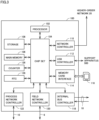
- Fig. 3 is a schematic diagram showing an exemplary hardware configuration of standard control unit 100 included in control system 1 according to the present embodiment.
- standard control unit 100 includes a processor 102, a chip set 104, a main memory 106, a storage 108, a network controller 110, a universal serial bus (USB) controller 112, a memory card interface 114, an internal bus controller 118, a field network controller 120, a process network controller 122, a counter 126, and a real time clock (RTC) 128.
- Processor 102 corresponds to a computing processing unit that performs a control operation or the like, and is configured with a central processing unit (CPU), a micro processing unit (MPU), or a graphics processing unit (GPU). Specifically, processor 102 performs an operation involved with standard control and communication processing as will be described later by reading a program (by way of example, a system program and a standard control program (a user program)) stored in storage 108, developing the program on main memory 106, and executing the program.
- Storage 108 is implemented, for example, by a non-volatile storage device such as a hard disk drive (HDD) or a solid state drive (SSD).
- Main memory 106 is implemented by a volatile storage device such as a dynamic random access memory (DRAM) or a static random access memory (SRAM).
- DRAM dynamic random access memory
- SRAM static random access memory
- a standard control program for realizing standard control created in conformity with an object to be controlled such as a facility or a machine is stored in storage 108.
- Network controller 110 exchanges data with an arbitrary information processing apparatus such as a gateway or a database server over higher-order network 20.
- USB controller 112 exchanges data with support apparatus 500 through USB connection.
- Memory card interface 114 is constructed such that a memory card 116 is attachable thereto and detachable therefrom, and allows writing of data into memory card 116 and reading of various types of data (a standard control program or trace data) from memory card 116.
- Internal bus controller 118 corresponds to a communication interface for electrical connection of standard control unit 100 to safety control unit 200 and functional unit 350 through internal bus 18. Internal bus controller 118 functions as a communication master for cyclic communication through internal bus 18.
- Field network controller 120 corresponds to a communication interface for electrical connection between standard control unit 100 and remote IO apparatus 4 over field network 6.
- Field network controller 120 functions as a communication master for cyclic communication over field network 6.
- Process network controller 122 corresponds to a communication interface for electrical connection between standard control unit 100 and safety driver 12 over process network 10.
- Process network controller 122 is responsible for communication control for exchange of data in each predetermined cycle time over process network 10.
- Counter 126 is used as time reference for managing timing of execution of various programs to be executed in standard control unit 100.
- RTC 128 is a kind of counter with a time counting function and provides current time to processor 102 or the like.
- Fig. 3 shows an exemplary configuration in which a necessary function is provided by execution of a program by processor 102
- a part or the entirety of these provided functions may be performed by using dedicated hardware circuitry (for example, an ASIC or an FPGA).
- a principal part of standard control unit 100 may be implemented by hardware (for example, an industrial personal computer based on a general-purpose personal computer) in accordance with a general-purpose architecture.
- a plurality of operating systems (OSs) different in application may be executed in parallel and a necessary application may be executed on each OS.
- OSs operating systems
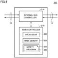
- Fig. 4 is a schematic diagram showing an exemplary hardware configuration of safety control unit 200 included in control system 1 according to the present embodiment.
- safety control unit 200 includes an internal bus controller 218 and a main controller 210.
- Internal bus controller 218 corresponds to a communication interface for electrical connection between standard control unit 100 and safety control unit 200 through internal bus 18. Internal bus controller 218 functions as a communication slave for participating in data communication through internal bus 18.
- Main controller 210 includes a processor 202, a main memory 204, and a storage 208.
- Processor 202 corresponds to a computing processing unit that performs a control operation or communication processing and is configured with a CPU, an MPU, or a GPU. Specifically, processor 202 carries out safety control or the like by reading a safety program 220 stored in storage 208, developing the safety program on main memory 204, and executing the safety program.
- Fig. 5 is a schematic diagram showing an exemplary hardware configuration of support apparatus 500 included in control system 1 according to the present embodiment.
- Support apparatus 500 is implemented by hardware (for example, a general-purpose personal computer) in accordance with a general-purpose architecture by way of example.
- Processor 502 is configured with a CPU, an MPU, or a GPU, and performs various types of processing as will be described later by reading a program (an OS 5102 and a support program 5104 by way of example) stored in storage 510, developing the program on main memory 504, and executing the program.
- a program an OS 5102 and a support program 5104 by way of example
- Main memory 504 is implemented by a volatile storage device such as a DRAM or an SRAM.
- Storage 510 is implemented by a non-volatile storage device such as an HDD or an SSD.
- support program 5104 for providing a function as support apparatus 500 is stored in storage 510.
- Support program 5104 provides a development environment for performing at least a part of creation of contents of processing performed by standard control unit 100 and making of settings involved with communication processing.
- project data 5106 created by a user in the development environment provided by execution of support program 5104 is stored in storage 510.
- Support apparatus 500 provides the development environment that allows, in an integrated manner, settings for each device included in control system 1 and creation of a program to be executed in each device.
- Project data 5106 includes data generated in such an integrated development environment.
- project data 5106 includes a standard control source program 5108, standard controller setting information 5110, a safety source program 5112, safety controller setting information 5114, and safety driver setting information 5116.
- Safety source program 5112 is converted to an object code, then transmitted to safety control unit 200, and stored as safety program 220 (see Fig. 4 ). Similarly, safety controller setting information 5114 is also transmitted to safety control unit 200.
- Safety driver setting information 5116 is transmitted to safety driver 12.
- Input device 506 is constituted of a keyboard, a mouse, and the like, and accepts an operation by a user.
- Output device 508 is constituted of a display, various indicators, a printer, and the like, and provides a result of processing from processor 502.
- USB controller 520 exchanges data with standard control unit 100 and the like through USB connection.
- Support apparatus 500 includes optical drive 512.
- a program stored in a recording medium 514 in which a computer readable program is stored in a non-transitory manner is read from the recording medium and installed in storage 510 or the like.
- an optical recording medium such as a digital versatile disc (DVD)
- support program 5104 and the like executed in support apparatus 500 may be installed from computer readable recording medium 514, it may be installed as being downloaded from a server apparatus over a network.
- a function provided by support apparatus 500 according to the present embodiment may be performed by using a part of a module provided by the OS.
- FIG. 5 shows an exemplary configuration in which a necessary function as support apparatus 500 is provided by execution of a program by processor 502, a part or the entirety of these provided functions may be performed by using dedicated hardware circuitry (for example, an ASIC or an FPGA).
- dedicated hardware circuitry for example, an ASIC or an FPGA.
- support apparatus 500 may be detached from standard control unit 100.
- Fig. 6 is a schematic diagram for illustrating FSoE in control system 1 according to the present embodiment.
- Fig. 6 shows an example in which data collected by safety functional unit 360 connected through a bus to coupler unit 300 is transmitted to safety control unit 200 in a configuration in which standard control unit 100 and coupler unit 300 are connected to each other over field network 6.
- Standard control unit 100 obtains input data collected by the functional unit through frames periodically transmitted over field network 6.
- Standard control unit 100 performs a control operation based on obtained input data and transmits in frames, a control instruction (output data) obtained by performing the control operation to the functional unit.
- standard control unit 100 periodically executes a control task 150 in correspondence with a frame transmission cycle time over field network 6.
- standard control unit 100 implementing control device 2 periodically performs a control operation for controlling an object to be controlled.
- IO refresh processing 152 In each cycle of execution (task cycle time) of control task 150, IO refresh processing 152, user program execution processing 154 such as a sequence operation, motion program execution processing 156, and the like is performed.
- IO refresh processing 152 is processing for updating data included in a frame transmitted over field network 6 to a state that can be referred to in standard control unit 100.
- the frame transmission cycle time is normally set to coincide with the task cycle time in standard control unit 100.
- Standard control unit 100 mediates data for implementing FSoE.
- Processing for transferring data transmitted over field network 6 to safety control unit 200 and processing for storing data transmitted from safety control unit 200 in frames and sending the frames over field network 6 is performed as a part of IO refresh processing 152 included in control task 150.
- FSoE data loopback processing is performed as a part of IO refresh processing 152, responsiveness of FSoE can be secured.
- a time period required for exchange of data in conformity with FSoE is guaranteed as a time period determined in accordance with the task cycle time (that is, the transmission cycle time).
- Fig. 7 is a schematic diagram for illustrating CIP Safety in control system 1 according to the present embodiment.
- Fig. 7 shows an example in which data is exchanged between safety control unit 200 and safety driver 12 in a configuration in which standard control unit 100 and safety driver 12 representing an exemplary slave device are connected to each other over process network 10.
- a frame (a CIP Safety frame) is exchanged for each connection defined in advance between standard control unit 100 and each slave device (safety driver 12 in the example shown in Fig. 7 ).
- An expected packet interval (EPI) is set in advance as a cycle time within which exchange of a frame for each connection can be completed.
- EPI expected packet interval
- all CIP Safety frames corresponding to each connection are generated and transmitted at least once within a corresponding EPI.
- the EPI may be defined for each communication counterpart device (target device).
- Standard control unit 100 transfers a frame received from each slave device to safety control unit 200 through internal bus 18.
- standard control unit 100 functions as a bridge that mediates frame transfer between each slave device and safety control unit 200.
- the function as the bridge is performed as communication processing 160 independent of control task 150.
- a CIP Safety communication service 162 for processing a CIP Safety frame in conformity with CIP Safety is performed.
- Fig. 8 is a schematic diagram showing an exemplary functional configuration for implementing CIP Safety in control device 2 according to the present embodiment.
- control device 2 includes CIP Safety communication service 162, a CIP Safety protocol stack 164, and a safety control executer 250 as functions in connection with CIP Safety.
- CIP Safety communication service 162 corresponds to a processing module configured to process a CIP Safety frame. Specifically, CIP Safety communication service 162 receives a CIP Safety frame from a slave device and provides the received CIP Safety frame to CIP Safety protocol stack 164. CIP Safety communication service 162 transmits the CIP Safety frame to a destination slave device in response to an instruction from CIP Safety protocol stack 164.
- CIP Safety protocol stack 164 manages exchange of a CIP Safety frame in conformity with CIP Safety. Specifically, CIP Safety protocol stack 164 analyzes the provided CIP Safety frame and provides data (input data) included therein to safety control executer 250. CIP Safety protocol stack 164 generates a CIP Safety frame in accordance with a control instruction (output data) from safety control executer 250 and provides the CIP Safety frame to CIP Safety communication service 162.
- Safety control executer 250 calculates a control instruction (output data) by performing a control operation involved with safety control based on the input data from CIP Safety protocol stack 164.
- Fig. 9 is a schematic diagram showing an exemplary implementation of the functional configuration shown in Fig. 8 .
- Fig. 9 (a) shows an exemplary configuration including standard control unit 100 and safety control unit 200.
- CIP Safety communication service 162 is implemented in standard control unit 100
- CIP Safety protocol stack 164 and safety control executer 250 are implemented in safety control unit 200.
- Fig. 9 (b) shows an exemplary configuration in which all functions are implemented in safety control unit 200.
- CIP Safety communication service 162, CIP Safety protocol stack 164, and safety control executer 250 are implemented in safety control unit 200.
- Standard control unit 100 or safety control unit 200 that implements control device 2 thus performs communication processing for periodically exchanging data with a slave device.
- a shorter EPI means a shorter cycle time of update of data. Therefore, in consideration of control performance or the like, the EPI preferably as short as possible is set.
- a settable EPI is determined under restrictions as shown below.
- a settable range of the EPI is determined based on at least one of such restriction factors.
- Each restriction factor will be described below.
- control system 1 Various types of settings for a unit that affect responsiveness of CIP Safety include each cycle time of execution (task cycle time) of control task 150. Therefore, in control system 1 according to the present embodiment, the settable range of the EPI may be determined based on a cycle time (task cycle time) of a control operation performed in standard control unit 100.
- Contents of settings for CIP Safety include the number of connections and a data size in CIP Safety.
- the number of connections in CIP Safety may include both of the number of connections (the maximum number) specifically supported by control system 1 and the number of connections arbitrarily set by a user.
- the data size in CIP Safety may encompass both of a size of data allocated to each connection and total data allocated to all connections.
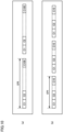
- Fig. 10 is a schematic diagram for illustrating exemplary contents of settings for CIP Safety in control device 2 according to the present embodiment.
- Fig. 10 (a) shows an example in which connections C1 to C100 are set and
- Fig. 10 (b) shows an example in which connections C1 to C10 are set.
- the settable range of the EPI may be determined based on at least one of the number of connections and a data size of data exchanged with a slave device.
- the EPI can also be defined for each target device.
- the settable range of the EPI may be determined for each device with which control device 2 exchanges data.
- Processing capability (spec) of a unit that provides CIP Safety communication service 162 means hardware performance of a unit (standard control unit 100 or safety control unit 200 as shown in Fig. 9 ) in which CIP Safety communication service 162 is implemented. Such processing capability (spec) is dependent on performance of a processor mounted on the unit, a memory capacity, a data transmission rate, and the like.
- control system 1 the settable range of the EPI may be determined based on processing capability of control device 2 (standard control unit 100 and safety control unit 200).
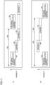
- Fig. 11 is a schematic diagram for illustrating exemplary execution of the CIP Safety communication service in control device 2 according to the present embodiment.
- Fig. 11 shows exemplary execution in the unit (standard control unit 100 or safety control unit 200) that provides CIP Safety communication service 162.
- a common resource is used to perform a service X 166 and a service Y 167 in addition to CIP Safety communication service 162.
- Fig. 11 (a) shows an example in which CIP Safety communication service 162 is performed with priority higher than other services being placed thereon
- Fig. 11 (b) shows an example in which CIP Safety communication service 162 is performed with priority lower than other services being placed thereon.
- CIP Safety communication service 162 when CIP Safety communication service 162 is higher in priority than other services as shown in Fig. 11 (a) , the EPI can be shorter because CIP Safety communication service 162 is preferentially performed.
- Responsiveness (that is, the minimum value of the EPI) of CIP Safety thus varies depending on contents of the service performed in the unit that provides CIP Safety communication service 162 and the priority defined for each service. Therefore, in control system 1 according to the present embodiment, the settable range of the EPI may be determined based on the priority defined for a control operation performed in standard control unit 100.
- activation or inactivation of execution can be set in advance. At least one of services, however, cannot be inactivated, and execution thereof may be fixed.
- the priority in the unit that provides CIP Safety communication service 162 can arbitrarily be set.
- the priority of at least one of services may also be set to a designed value.
- the settable range of the EPI may be determined with both of the restriction factor (by way of example, (1), (4-1), and (4-2) described above) determined in accordance with contents of processing performed by standard control unit 100 and safety control unit 200 that implement control device 2 and the restriction factor (by way of example, (2) described above) determined in accordance with settings involved with communication processing being reflected.
- Control device 1 can also provide a function to support settings of responsiveness (the length of the EPI) of CIP Safety with the restriction factors as described above being reflected.
- the function to support settings of responsiveness (the length of the EPI) of CIP Safety will be described below.
- control system 1 can automatically calculate a minimum value of the settable EPI determined in accordance with performance of the unit and current settings.
- Fig. 12 is a diagram showing an exemplary parameter table 170 used for calculating a minimum value of the EPI settable in control system 1 according to the present embodiment.
- parameter table 170 includes parameter values including a first parameter 172, a second parameter 174, and a third parameter group 176 for each type of a controller (typically, standard control unit 100) by way of example.
- First parameter 172 reflects a restriction factor for "(1) Various types of settings for unit that affect responsiveness of CIP Safety.”
- Second parameter 174 reflects a restriction factor for "(2) Contents of settings for CIP Safety.”
- Third parameter group 176 reflects a restriction factor for "(4-1) Other services provided by unit that provides CIP Safety communication service 162" and "(4-2) Priority in unit that provides CIP Safety communication service 162.”
- First parameter 172, second parameter 174, and third parameter group 176 each reflect the restriction factor for "(3) Processing capability (spec) of unit that provides CIP Safety communication service 162.”
- a set value Ts represents each cycle time (task cycle time) of execution of control task 150. In other words, set value Ts means an IO refresh cycle time.
- a set value Sc represents the number of connections of CIP Safety. A data size of CIP Safety may be employed as set value Sc.
- Parameter values (parameter values c, d, and e) in third parameter group 176 reflect a service to be performed, priority, and the like. Therefore, when the service performed in the controller of interest or the priority is changed, the minimum value of the settable EPI may be calculated again in accordance with the changed contents of settings.
- Fig. 13 is a diagram for illustrating processing for calculating again the minimum value of the EPI settable in control system 1 according to the present embodiment. Referring to Fig. 13 , when contents of the service performed in the controller of interest or the priority defined for the service are/is changed, an applied parameter may be selected again and the minimum value of the settable EPI may be calculated again.
- priority of CIP Safety communication service 162 is highest next to service X 166.
- Service Y 167 and a service Z 168 are lower in priority than CIP Safety communication service 162.
- a predetermined value may be set as the maximum value of the EPI.
- any value smaller than a time period on which determination as a communication error (time-out) is based may be set as the maximum value of the EPI.
- a function to calculate the minimum value of the settable EPI as described above is typically implemented in support apparatus 500.
- a functional configuration in an implementation in support apparatus 500 will be described below.
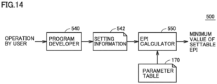
- Fig. 14 is a block diagram showing an exemplary functional configuration of support apparatus 500 included in control system 1 according to the present embodiment.
- a main function shown in Fig. 14 is performed by execution of support program 5104 by processor 502 of support apparatus 500 ( Fig. 5 ).
- support apparatus 500 includes a program developer 540 and an EPI calculator 550.
- Program developer 540 provides an interface for developing a program to be executed in control device 2 and for making necessary settings.
- Program developer 540 generates project data 5106 (see Fig. 5 or the like) including standard control source program 5108, standard controller setting information 5110, safety source program 5112, safety controller setting information 5114, and safety driver setting information 5116, in accordance with an operation by a user.
- Program developer 540 thus provides a development environment for performing at least a part of creation of contents of processing performed by standard control unit 100 and safety control unit 200 that implement control device 2 and making of settings involved with communication processing.
- EPI calculator 550 calculates the minimum value of the settable EPI based on setting information 542 (including standard controller setting information 5110 and safety controller setting information 5114) generated by program developer 540 and parameter table 170 (see Fig. 12 ).
- the minimum value of the settable EPI calculated by EPI calculator 550 may be presented to a user through output device 508 (see Fig. 5 and the like) such as a display.
- EPI calculator 550 thus determines a settable range of a cycle time (EPI) of exchange of data with a slave device based on contents set in the development environment provided by program developer 540.
- EPI cycle time
- An exemplary user interface screen for presenting to a user, a result of calculation of the minimum value of the settable EPI as described above will now be described.
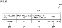
- Fig. 15 is a diagram showing an exemplary user interface screen provided by control system 1 according to the present embodiment.
- a user interface screen 570 shown in Fig. 15 may typically be shown on support apparatus 500.
- user interface screen 570 includes an EPI settable range 572 brought in correspondence with setting information 574.
- Setting information 574 includes a task cycle time 575 (setting Ts), the number of connections 576 (setting Sc), and type information 577 as setting items.
- Support apparatus 500 thus calculates the minimum value of the settable EPI and presents the minimum value to the user, together with setting information corresponding to calculation of the EPI.
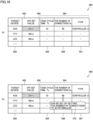
- Fig. 16 is a diagram showing another exemplary user interface screen provided by control system 1 according to the present embodiment.
- a current EPI set value 582 is shown for each target device 588.
- Setting information 584 (a task cycle time 585 (setting Ts), the number of connections 586 (setting Sc), and type information 587) is shown in correspondence with EPI set value 582 for each target device 588.
- EPI set value 582 When EPI set value 582 is smaller than the minimum value of the settable EPI calculated based on corresponding setting information 584 (that is, out of the settable range), an error may be presented to the user.
- the error may be presented in any form, and for example, such a manner that a color of a character or a background of corresponding EPI set value 582 is different from that in a normal manner of representation may be adopted.
- Fig. 16 shows an example in which an attention representation 589 for presenting an error is given for EPI set value 582.
- corresponding EPI set value 582 may blink or an audio notification may be given.
- a message 579 that suggests change of contents of settings in setting information 584 may be shown such that the EPI is within the settable range.
- a message indicating that EPI set value 582 can be within the settable range by reducing the number of connections 586 (setting Sc) is presented.
- Contents included in message 579 that suggest change of contents of settings are determined by generation by support apparatus 500, of some candidates different in setting information 584 and calculation of the minimum value of the settable EPI for each candidate.
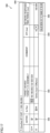
- Fig. 17 is a diagram showing yet another exemplary user interface screen provided by control system 1 according to the present embodiment.
- a user interface screen 590 shown in Fig. 17 provides an interface for making settings involved with CIP Safety.
- User interface screen 590 includes information on connection defined for a port to be set.
- user interface screen 590 includes a flag 592 for selecting activation or inactivation of settings of connection, setting 593 of data allocated to connection of interest, a minimum value 594 of the corresponding settable EPI, and a time period 596 for network response to a communication counterpart device (target device).
- Time period 596 for network response may be set to a value calculated by simulation or a value obtained by actual measurement (an actually measured value).
- an error message 595 including the settable range may be shown.
- support apparatus 500 may perform a notification function to give a notification when a set value of a cycle time of exchange of data with a slave device is out of the settable range of the EPI.
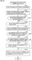
- Fig. 18 is a flowchart showing an exemplary procedure of processing performed in support apparatus 500 included in control system 1 according to the present embodiment. Each step shown in Fig. 18 is performed by execution of support program 5104 by processor 502 of support apparatus 500 ( Fig. 5 ).
- support apparatus 500 starts providing the development environment in response to an operation by a user (step S100). Specifically, support apparatus 500 performs processing for providing the development environment for performing at least a part of creation of contents of processing performed by standard control unit 100 and making of settings involved with communication processing.
- Support apparatus 500 generates a program and determines various types of setting information in response to an operation by the user (step S102). Then, support apparatus 500 determines whether or not information necessary for calculation of the minimum value of the settable EPI is ready (step S104). When information necessary for calculation of the minimum value of the settable EPI is not ready (NO in step S104), support apparatus 500 repeats processing in step S102 or later.
- support apparatus 500 selects one device (target device) of interest of calculation (step S106) and calculates the minimum value of the settable EPI based on relevant setting information (step S108). In other words, support apparatus 500 performs processing for determining the settable range of the EPI which is a cycle time of exchange of data with a slave device, based on contents set in the development environment.
- support apparatus 500 determines whether or not the minimum value of the settable EPI has been calculated for all devices of interest of calculation (step S110). When there remains a device for which the minimum value of the settable EPI has not been calculated (NO in step S110), support apparatus 500 repeats processing in step S106 or later.
- support apparatus 500 determines whether or not there is an EPI smaller in minimum value of the corresponding settable EPI among one or more currently set EPIs (step S112).
- support apparatus 500 specifies the EPI smaller in minimum value of the settable EPI (step S 114).
- processing in step S 114 is skipped.
- support apparatus 500 presents to a user, the calculated minimum value of the settable EPI and an error for the EPI smaller in minimum value of the settable EPI (step S 116). Then, the process ends.
- support apparatus 500 calculates the minimum value of the settable EPI
- any processing entity can calculate the minimum value of the settable EPI.
- a controller standard control unit 100 or safety control unit 200
- a computer arranged on a cloud may calculate the minimum value of the EPI based on setting information provided from support apparatus 500.
- any processing entity may perform the method of calculating the minimum value of the settable EPI according to the present embodiment.
- CIP Safety is mainly described in detail in the description above. Without being limited to CIP Safety, however, the present invention is widely applicable to data communication in which data of a predetermined data size is periodically exchanged with one or more communication counterparts. For example, the present invention is applicable to normal frame transmission in conformity with EtherNet/IP TM .
- Control device 2 including standard control unit 100 and safety control unit 200 independent of each other is exemplified in the description above. Without being limited to such a configuration, however, a single controller in which functions of both of these units are integrated may be implemented. Since the essence of the present invention resides in communication processing, control device 2 including both of standard control unit 100 and safety control unit 200 does not necessarily have to be employed but the control device may be configured to include only any one of the units.
- a settable range of a cycle time (EPI) of exchange of data between control device 2 and a slave device can be determined based on contents of processing performed in control device 2 and settings involved with communication processing. Therefore, even a user with less knowledge can set an appropriate cycle time. Thus, occurrence of failure such as communication disconnection due to expiration of the cycle time can be prevented in control devices of various types that are variously set depending on an object to be controlled.
- EPI cycle time
- the settable range of the cycle time (EPI) of exchange of data can be known in advance, and hence apparatus design can readily be made.
Landscapes
- Engineering & Computer Science (AREA)
- Physics & Mathematics (AREA)
- General Physics & Mathematics (AREA)
- Automation & Control Theory (AREA)
- Computer Networks & Wireless Communication (AREA)
- Signal Processing (AREA)
- Programmable Controllers (AREA)
Claims (10)
- Steuersystem (1), umfassend eine Steuervorrichtung (2) und eine Vorrichtung (12), die dazu ausgelegt ist, mit der Steuervorrichtung zu kommunizieren, wobei das Steuersystem Folgendes umfasst:ein Kommunikationsverarbeitungsmittel (100), das dazu ausgelegt ist, eine Kommunikationsverarbeitung (160) zum periodischen Austauschen von Datenrahmen mit der Vorrichtung über ein Feldnetzwerk gemäß einem Rahmenübertragungszyklus durchzuführen;ein Steuermittel (200), das über einen internen Bus (18) mit dem Kommunikationsverarbeitungsmittel verbunden ist, wobei das Kommunikationsverarbeitungsmittel dazu ausgelegt ist, einen Rahmentransfer zwischen der Vorrichtung und dem Steuermittel zu vermitteln, wobei das Steuermittel dazu ausgelegt ist, um periodisch einen Steuervorgang (150) zum Steuern der Vorrichtung durchzuführen, wobei der Steuervorgang das Bestimmen eines Steuerbefehls beruhend auf Eingangsdaten, die von einem von der Vorrichtung empfangenen Rahmen erhalten wurden, umfasst, wobei das Steuermittel dazu ausgelegt ist, den Steuerbefehl in einen Rahmen zur Übertragung an die Vorrichtung aufzunehmen;ein Bereitstellungsmittel (500, 540), das dazu ausgelegt ist, eine Entwicklungsumgebung zum Durchführen von zumindest einem Teil der Erstellung eines Inhalts von Verarbeitung, die durch das Steuermittel durchgeführt wird, bereitzustellen und Einstellungen, die an der Kommunikationsverarbeitung durch das Kommunikationsverarbeitungsmittel beteiligt sind, vorzunehmen; undein Bestimmungsmittel (500, 550), das dazu ausgelegt ist, einen einstellbaren Bereich einer Zykluszeit des Rahmenübertragungszyklus für den Austausch von Datenrahmen mit der Vorrichtung beruhend auf einem Inhalt, der in der vom Bereitstellungsmittel bereitgestellten Entwicklungsumgebung eingestellt ist, zu bestimmen.
- Steuersystem nach Anspruch 1, wobei
das Bestimmungsmittel dazu ausgelegt ist, den einstellbaren Bereich zu bestimmen, wobei sowohl ein Beschränkungsfaktor, der entsprechend dem Inhalt der vom Steuermittel durchgeführten Verarbeitung bestimmt wird, als auch ein Beschränkungsfaktor, der entsprechend Einstellungen, die an der durch das Kommunikationsverarbeitungsmittel durchgeführten Kommunikationsverarbeitung beteiligt sind, bestimmt wird, reflektiert werden. - Steuersystem nach Anspruch 1 oder 2, wobei
das Bestimmungsmittel dazu ausgelegt ist, den einstellbaren Bereich beruhend auf zumindest einem aus der Anzahl von Verbindungen und einer Datengröße von mit der Vorrichtung ausgetauschten Daten zu bestimmen. - Steuersystem nach einem der Ansprüche 1 bis 3, wobei
das Bestimmungsmittel dazu ausgelegt ist, den einstellbaren Bereich beruhend auf einer Zykluszeit des vom Steuermittel durchgeführten Steuervorgangs zu bestimmen. - Steuersystem nach einem der Ansprüche 1 bis 4, wobei
das Bestimmungsmittel dazu ausgelegt ist, den einstellbaren Bereich beruhend auf einer für den vom Steuermittel durchgeführten Steuervorgang definierten Priorität zu bestimmen. - Steuersystem nach einem der Ansprüche 1 bis 5, wobei
das Bestimmungsmittel dazu ausgelegt ist, den einstellbaren Bereich beruhend auf der Verarbeitungskapazität der Steuervorrichtung zu bestimmen. - Steuersystem nach einem der Ansprüche 1 bis 6, wobei
das Bestimmungsmittel dazu ausgelegt ist, den einstellbaren Bereich für jede Vorrichtung, mit der die Steuervorrichtung Daten austauscht, zu bestimmen. - Steuersystem nach einem der Ansprüche 1 bis 7, ferner umfassend ein Benachrichtigungsmittel, das dazu ausgelegt sind, eine Benachrichtigung auszugeben, wenn ein eingestellter Wert der Zykluszeit des Austauschs von Daten mit der Vorrichtung außerhalb des einstellbaren Bereichs liegt, der durch das Bestimmungsmittel bestimmt wurde.
- Steuersystem nach einem der vorangegangenen Ansprüche, wobei das Bereitstellungsmittel und das Bestimmungsmittel als Teil einer Unterstützungsvorrichtung (500) implementiert sind.
- Programm (5104) für eine Unterstützungsvorrichtung (500) für ein Steuersystem (1), umfassend eine Steuervorrichtung und eine Vorrichtung, die dazu ausgelegt ist, mit der Steuervorrichtung zu kommunizieren, wobei die Steuervorrichtung Folgendes umfasst: ein Kommunikationsverarbeitungsmittel (100), das dazu ausgelegt ist, eine Kommunikationsverarbeitung (160) zum periodischen Austauschen von Datenrahmen mit der Vorrichtung über ein Feldnetzwerk gemäß einem Rahmenübertragungszyklus durchzuführen, und ein Steuermittel (200), das über einen internen Bus (18) mit dem Kommunikationsverarbeitungsmittel verbunden ist, wobei das Kommunikationsverarbeitungsmittel dazu ausgelegt ist, einen Rahmentransfer zwischen der Vorrichtung und dem Steuermittel zu vermitteln, wobei das Steuermittel dazu ausgelegt ist, periodisch einen Steuervorgang zum Steuern der Vorrichtung durchzuführen, wobei der Steuervorgang das Bestimmen eines Steuerbefehls beruhend auf Eingangsdaten, die von einem von der Vorrichtung empfangenen Rahmen erhalten wurden, umfasst, und wobei das Steuermittel dazu ausgelegt ist, den Steuerbefehl in einen Rahmen zur Übertragung an die Vorrichtung aufzunehmen;
wobei das Programm, wenn es von einem Computer ausgeführt wird, bewirkt, dass der Computer Folgendes durchführt:Bereitstellen einer Entwicklungsumgebung zum Durchführen von zumindest einem Teil der Erstellung eines Inhalts von Verarbeitung, die durch das Steuermittel durchgeführt wird, und Vornehmen von Einstellungen, die an der Kommunikationsverarbeitung durch das Kommunikationsverarbeitungsmittel beteiligt sind (S100); undBestimmen eines einstellbaren Bereichs einer Zykluszeit des Rahmenübertragungszyklus für den Austausch von Daten mit der Vorrichtung beruhend auf einem Inhalt, der in der Entwicklungsumgebung eingestellt ist (S108).
Applications Claiming Priority (2)
| Application Number | Priority Date | Filing Date | Title |
|---|---|---|---|
| JP2019047166A JP7003952B2 (ja) | 2019-03-14 | 2019-03-14 | 制御システム、サポート装置およびサポート装置用のプログラム |
| PCT/JP2020/005273 WO2020184035A1 (ja) | 2019-03-14 | 2020-02-12 | 制御システム、サポート装置およびサポート装置用のプログラム |
Publications (3)
| Publication Number | Publication Date |
|---|---|
| EP3940468A1 EP3940468A1 (de) | 2022-01-19 |
| EP3940468A4 EP3940468A4 (de) | 2022-12-07 |
| EP3940468B1 true EP3940468B1 (de) | 2024-10-23 |
Family
ID=72426171
Family Applications (1)
| Application Number | Title | Priority Date | Filing Date |
|---|---|---|---|
| EP20769324.3A Active EP3940468B1 (de) | 2019-03-14 | 2020-02-12 | Steuerungssystem, unterstützungsvorrichtung und programm für unterstützungsvorrichtung |
Country Status (5)
| Country | Link |
|---|---|
| US (1) | US11917024B2 (de) |
| EP (1) | EP3940468B1 (de) |
| JP (1) | JP7003952B2 (de) |
| CN (1) | CN113498495B (de) |
| WO (1) | WO2020184035A1 (de) |
Families Citing this family (2)
| Publication number | Priority date | Publication date | Assignee | Title |
|---|---|---|---|---|
| JP2023152149A (ja) * | 2022-04-01 | 2023-10-16 | オムロン株式会社 | 開発支援装置、開発支援プログラム、及び開発支援方法 |
| CN119487463B (zh) * | 2022-09-21 | 2025-11-28 | 三菱电机株式会社 | 设定辅助装置、控制系统、设定辅助方法以及记录介质 |
Family Cites Families (25)
| Publication number | Priority date | Publication date | Assignee | Title |
|---|---|---|---|---|
| JPH10307613A (ja) * | 1997-05-07 | 1998-11-17 | Mitsubishi Electric Corp | プロセスデータ収集装置の更新方法 |
| JP2002353984A (ja) | 2001-05-30 | 2002-12-06 | Yaskawa Electric Corp | I/o伝送システム |
| JP2004318508A (ja) | 2003-04-16 | 2004-11-11 | Yaskawa Electric Corp | I/o伝送システム |
| US7831680B2 (en) * | 2004-07-16 | 2010-11-09 | National Instruments Corporation | Deterministic communication between graphical programs executing on different computer systems |
| US20060212530A1 (en) * | 2005-03-21 | 2006-09-21 | Dexterra, Inc. | Adapter architecture for mobile data system |
| JP4005614B2 (ja) * | 2005-11-04 | 2007-11-07 | 株式会社コナミデジタルエンタテインメント | ネットワークゲームシステム、ゲーム装置、ゲーム装置の制御方法及びプログラム |
| JP4941365B2 (ja) | 2008-03-13 | 2012-05-30 | オムロン株式会社 | 産業用コントローラ |
| JP2010198600A (ja) | 2009-02-02 | 2010-09-09 | Omron Corp | 産業用コントローラ |
| EP2672341B1 (de) * | 2011-01-31 | 2015-09-09 | Toyota Jidosha Kabushiki Kaisha | Sicherheitssteuerungsvorrichtung und sicherheitssteuerungsverfahren |
| JP5340376B2 (ja) * | 2011-12-28 | 2013-11-13 | 楽天株式会社 | 検索装置、検索方法、検索プログラム及び記録媒体 |
| JP6263836B2 (ja) | 2013-01-15 | 2018-01-24 | オムロン株式会社 | 制御装置および制御方法 |
| JP6390113B2 (ja) * | 2014-02-14 | 2018-09-19 | オムロン株式会社 | 制御システム、開発支援装置、制御装置、および制御方法 |
| US10444715B2 (en) * | 2014-05-01 | 2019-10-15 | Belkin International, Inc. | Controlling settings and attributes related to operation of devices in a network |
| JP6498557B2 (ja) | 2015-07-28 | 2019-04-10 | 株式会社日立産機システム | プログラマブルコントローラ |
| CN106227140B (zh) * | 2016-08-06 | 2019-04-09 | 山东华旗新能源科技有限公司 | 智慧供水管理系统 |
| JP7089842B2 (ja) | 2016-10-07 | 2022-06-23 | オムロン株式会社 | 演算装置および制御装置 |
| JP6769230B2 (ja) * | 2016-10-14 | 2020-10-14 | オムロン株式会社 | 通信装置、制御装置および通信方法 |
| JP6753278B2 (ja) * | 2016-11-22 | 2020-09-09 | オムロン株式会社 | 制御システムおよび制御装置 |
| JP6428805B2 (ja) | 2017-02-07 | 2018-11-28 | オムロン株式会社 | 演算装置、制御装置および制御方法 |
| JP6406466B1 (ja) * | 2017-04-07 | 2018-10-17 | オムロン株式会社 | 制御装置、制御方法および制御プログラム |
| JP6996887B2 (ja) * | 2017-07-11 | 2022-01-17 | 株式会社キーエンス | プログラマブル・ロジック・コントローラシステムおよびデータ収集装置 |
| JP6919404B2 (ja) * | 2017-08-10 | 2021-08-18 | オムロン株式会社 | 制御装置 |
| US12113870B2 (en) * | 2017-11-10 | 2024-10-08 | The Toronto-Dominion Bank | Automatic generation and provisioning of notification data to dynamically selected network-connected devices |
| CN112020704B (zh) * | 2018-04-18 | 2025-02-18 | 谷歌有限责任公司 | 用于执行应用更新周期的资源的设备间传输 |
| JP7095634B2 (ja) * | 2019-03-13 | 2022-07-05 | トヨタ自動車株式会社 | 自動更新システム、その更新方法及びプログラム |
-
2019
- 2019-03-14 JP JP2019047166A patent/JP7003952B2/ja active Active
-
2020
- 2020-02-12 US US17/435,246 patent/US11917024B2/en active Active
- 2020-02-12 CN CN202080017558.4A patent/CN113498495B/zh active Active
- 2020-02-12 WO PCT/JP2020/005273 patent/WO2020184035A1/ja not_active Ceased
- 2020-02-12 EP EP20769324.3A patent/EP3940468B1/de active Active
Also Published As
| Publication number | Publication date |
|---|---|
| JP7003952B2 (ja) | 2022-01-21 |
| US20220210247A1 (en) | 2022-06-30 |
| EP3940468A1 (de) | 2022-01-19 |
| CN113498495B (zh) | 2024-10-29 |
| CN113498495A (zh) | 2021-10-12 |
| WO2020184035A1 (ja) | 2020-09-17 |
| EP3940468A4 (de) | 2022-12-07 |
| US11917024B2 (en) | 2024-02-27 |
| JP2020149439A (ja) | 2020-09-17 |
Similar Documents
| Publication | Publication Date | Title |
|---|---|---|
| US11055082B2 (en) | Unified update tool for multi-protocol network adapter | |
| EP2533114B1 (de) | Steuerungsunterstützungsvorrichtung, in besagter vorrichtung ausführbares steuerungsunterstützungsprogramm, aufzeichnungsmedium zur speicherung des besagten programms und verfahren zur schätzung der ausführungsdauer des steuerungsprogramms | |
| US20190005168A1 (en) | Performance testing method and apparatus for industrial system deployed on cloud | |
| US8606905B1 (en) | Automated determination of system scalability and scalability constraint factors | |
| EP3582036A1 (de) | Steuerungsvorrichtung | |
| CN107967143A (zh) | 获取客户端应用程序源代码的更新指示信息的方法、装置和系统 | |
| EP3460596A1 (de) | Support-vorrichtung und support-programm | |
| Saunders et al. | AUTOPILOT: Automating experiments with lots of Raspberry Pis | |
| EP3940468B1 (de) | Steuerungssystem, unterstützungsvorrichtung und programm für unterstützungsvorrichtung | |
| CN114548448A (zh) | 一种运维服务管理方法、装置及系统 | |
| CN113544601B (zh) | 控制系统、设定装置以及记录介质 | |
| EP4102371A1 (de) | Systeme und verfahren zur nichtintrusiven überwachung der prozessinternen anwendungslatenzzeit | |
| CN112416700A (zh) | 分析启动的预测性故障和smart日志 | |
| EP3940471B1 (de) | Unterstützungsvorrichtung | |
| EP3789831B1 (de) | System und verfahren zur simulation von feldgeräten in industriellen anlagen | |
| CN110489304B (zh) | 系统间资源访问状态的监控方法和装置 | |
| Elmenreich et al. | Modeling distributed embedded applications on an interface file system | |
| EP4184257B1 (de) | Echtzeit-hochgeschwindigkeits-taktsignal zur emulation industrieller netzwerke | |
| US12141572B2 (en) | Method, device, and computer program product for upgrading virtual system | |
| Brunner et al. | Practical aspects of cross-vendor TSN time synchronization using IEEE 802.1 AS | |
| JP2019179475A (ja) | サポート装置、サポートプログラム、設定方法 | |
| WO2017203556A1 (ja) | 管理計算機及びシステムのパラメータの最適値算出方法 | |
| JP2022137666A (ja) | ネットワーク評価装置、ネットワーク評価方法およびネットワーク評価プログラム | |
| EP4546743A1 (de) | Steuerungssystem, relaisvorrichtung und kommunikationsverfahren | |
| EP4546742A1 (de) | Steuerungssystem, relaisvorrichtung und kommunikationsverfahren |
Legal Events
| Date | Code | Title | Description |
|---|---|---|---|
| STAA | Information on the status of an ep patent application or granted ep patent |
Free format text: STATUS: THE INTERNATIONAL PUBLICATION HAS BEEN MADE |
|
| PUAI | Public reference made under article 153(3) epc to a published international application that has entered the european phase |
Free format text: ORIGINAL CODE: 0009012 |
|
| STAA | Information on the status of an ep patent application or granted ep patent |
Free format text: STATUS: REQUEST FOR EXAMINATION WAS MADE |
|
| 17P | Request for examination filed |
Effective date: 20210901 |
|
| AK | Designated contracting states |
Kind code of ref document: A1 Designated state(s): AL AT BE BG CH CY CZ DE DK EE ES FI FR GB GR HR HU IE IS IT LI LT LU LV MC MK MT NL NO PL PT RO RS SE SI SK SM TR |
|
| DAV | Request for validation of the european patent (deleted) | ||
| DAX | Request for extension of the european patent (deleted) | ||
| A4 | Supplementary search report drawn up and despatched |
Effective date: 20221108 |
|
| RIC1 | Information provided on ipc code assigned before grant |
Ipc: G05B 19/05 20060101AFI20221031BHEP |
|
| GRAP | Despatch of communication of intention to grant a patent |
Free format text: ORIGINAL CODE: EPIDOSNIGR1 |
|
| GRAP | Despatch of communication of intention to grant a patent |
Free format text: ORIGINAL CODE: EPIDOSNIGR1 |
|
| STAA | Information on the status of an ep patent application or granted ep patent |
Free format text: STATUS: GRANT OF PATENT IS INTENDED |
|
| INTG | Intention to grant announced |
Effective date: 20240614 |
|
| GRAS | Grant fee paid |
Free format text: ORIGINAL CODE: EPIDOSNIGR3 |
|
| GRAA | (expected) grant |
Free format text: ORIGINAL CODE: 0009210 |
|
| STAA | Information on the status of an ep patent application or granted ep patent |
Free format text: STATUS: THE PATENT HAS BEEN GRANTED |
|
| AK | Designated contracting states |
Kind code of ref document: B1 Designated state(s): AL AT BE BG CH CY CZ DE DK EE ES FI FR GB GR HR HU IE IS IT LI LT LU LV MC MK MT NL NO PL PT RO RS SE SI SK SM TR |
|
| REG | Reference to a national code |
Ref country code: GB Ref legal event code: FG4D |
|
| REG | Reference to a national code |
Ref country code: CH Ref legal event code: EP |
|
| REG | Reference to a national code |
Ref country code: DE Ref legal event code: R096 Ref document number: 602020039952 Country of ref document: DE |
|
| REG | Reference to a national code |
Ref country code: IE Ref legal event code: FG4D |
|
| REG | Reference to a national code |
Ref country code: LT Ref legal event code: MG9D |
|
| REG | Reference to a national code |
Ref country code: NL Ref legal event code: MP Effective date: 20241023 |
|
| REG | Reference to a national code |
Ref country code: AT Ref legal event code: MK05 Ref document number: 1735335 Country of ref document: AT Kind code of ref document: T Effective date: 20241023 |
|
| PG25 | Lapsed in a contracting state [announced via postgrant information from national office to epo] |
Ref country code: NL Free format text: LAPSE BECAUSE OF FAILURE TO SUBMIT A TRANSLATION OF THE DESCRIPTION OR TO PAY THE FEE WITHIN THE PRESCRIBED TIME-LIMIT Effective date: 20241023 |
|
| PG25 | Lapsed in a contracting state [announced via postgrant information from national office to epo] |
Ref country code: NL Free format text: LAPSE BECAUSE OF FAILURE TO SUBMIT A TRANSLATION OF THE DESCRIPTION OR TO PAY THE FEE WITHIN THE PRESCRIBED TIME-LIMIT Effective date: 20241023 |
|
| PG25 | Lapsed in a contracting state [announced via postgrant information from national office to epo] |
Ref country code: PT Free format text: LAPSE BECAUSE OF FAILURE TO SUBMIT A TRANSLATION OF THE DESCRIPTION OR TO PAY THE FEE WITHIN THE PRESCRIBED TIME-LIMIT Effective date: 20250224 Ref country code: IS Free format text: LAPSE BECAUSE OF FAILURE TO SUBMIT A TRANSLATION OF THE DESCRIPTION OR TO PAY THE FEE WITHIN THE PRESCRIBED TIME-LIMIT Effective date: 20250223 Ref country code: HR Free format text: LAPSE BECAUSE OF FAILURE TO SUBMIT A TRANSLATION OF THE DESCRIPTION OR TO PAY THE FEE WITHIN THE PRESCRIBED TIME-LIMIT Effective date: 20241023 |
|
| PG25 | Lapsed in a contracting state [announced via postgrant information from national office to epo] |
Ref country code: FI Free format text: LAPSE BECAUSE OF FAILURE TO SUBMIT A TRANSLATION OF THE DESCRIPTION OR TO PAY THE FEE WITHIN THE PRESCRIBED TIME-LIMIT Effective date: 20241023 |
|
| PG25 | Lapsed in a contracting state [announced via postgrant information from national office to epo] |
Ref country code: BG Free format text: LAPSE BECAUSE OF FAILURE TO SUBMIT A TRANSLATION OF THE DESCRIPTION OR TO PAY THE FEE WITHIN THE PRESCRIBED TIME-LIMIT Effective date: 20241023 |
|
| PG25 | Lapsed in a contracting state [announced via postgrant information from national office to epo] |
Ref country code: ES Free format text: LAPSE BECAUSE OF FAILURE TO SUBMIT A TRANSLATION OF THE DESCRIPTION OR TO PAY THE FEE WITHIN THE PRESCRIBED TIME-LIMIT Effective date: 20241023 |
|
| PG25 | Lapsed in a contracting state [announced via postgrant information from national office to epo] |
Ref country code: NO Free format text: LAPSE BECAUSE OF FAILURE TO SUBMIT A TRANSLATION OF THE DESCRIPTION OR TO PAY THE FEE WITHIN THE PRESCRIBED TIME-LIMIT Effective date: 20250123 |
|
| PG25 | Lapsed in a contracting state [announced via postgrant information from national office to epo] |
Ref country code: LV Free format text: LAPSE BECAUSE OF FAILURE TO SUBMIT A TRANSLATION OF THE DESCRIPTION OR TO PAY THE FEE WITHIN THE PRESCRIBED TIME-LIMIT Effective date: 20241023 Ref country code: GR Free format text: LAPSE BECAUSE OF FAILURE TO SUBMIT A TRANSLATION OF THE DESCRIPTION OR TO PAY THE FEE WITHIN THE PRESCRIBED TIME-LIMIT Effective date: 20250124 Ref country code: AT Free format text: LAPSE BECAUSE OF FAILURE TO SUBMIT A TRANSLATION OF THE DESCRIPTION OR TO PAY THE FEE WITHIN THE PRESCRIBED TIME-LIMIT Effective date: 20241023 |
|
| PG25 | Lapsed in a contracting state [announced via postgrant information from national office to epo] |
Ref country code: PL Free format text: LAPSE BECAUSE OF FAILURE TO SUBMIT A TRANSLATION OF THE DESCRIPTION OR TO PAY THE FEE WITHIN THE PRESCRIBED TIME-LIMIT Effective date: 20241023 |
|
| PG25 | Lapsed in a contracting state [announced via postgrant information from national office to epo] |
Ref country code: RS Free format text: LAPSE BECAUSE OF FAILURE TO SUBMIT A TRANSLATION OF THE DESCRIPTION OR TO PAY THE FEE WITHIN THE PRESCRIBED TIME-LIMIT Effective date: 20250123 |
|
| PG25 | Lapsed in a contracting state [announced via postgrant information from national office to epo] |
Ref country code: SM Free format text: LAPSE BECAUSE OF FAILURE TO SUBMIT A TRANSLATION OF THE DESCRIPTION OR TO PAY THE FEE WITHIN THE PRESCRIBED TIME-LIMIT Effective date: 20241023 |
|
| PG25 | Lapsed in a contracting state [announced via postgrant information from national office to epo] |
Ref country code: DK Free format text: LAPSE BECAUSE OF FAILURE TO SUBMIT A TRANSLATION OF THE DESCRIPTION OR TO PAY THE FEE WITHIN THE PRESCRIBED TIME-LIMIT Effective date: 20241023 |
|
| PG25 | Lapsed in a contracting state [announced via postgrant information from national office to epo] |
Ref country code: EE Free format text: LAPSE BECAUSE OF FAILURE TO SUBMIT A TRANSLATION OF THE DESCRIPTION OR TO PAY THE FEE WITHIN THE PRESCRIBED TIME-LIMIT Effective date: 20241023 |
|
| PG25 | Lapsed in a contracting state [announced via postgrant information from national office to epo] |
Ref country code: RO Free format text: LAPSE BECAUSE OF FAILURE TO SUBMIT A TRANSLATION OF THE DESCRIPTION OR TO PAY THE FEE WITHIN THE PRESCRIBED TIME-LIMIT Effective date: 20241023 |
|
| REG | Reference to a national code |
Ref country code: DE Ref legal event code: R097 Ref document number: 602020039952 Country of ref document: DE |
|
| PG25 | Lapsed in a contracting state [announced via postgrant information from national office to epo] |
Ref country code: SK Free format text: LAPSE BECAUSE OF FAILURE TO SUBMIT A TRANSLATION OF THE DESCRIPTION OR TO PAY THE FEE WITHIN THE PRESCRIBED TIME-LIMIT Effective date: 20241023 |
|
| PG25 | Lapsed in a contracting state [announced via postgrant information from national office to epo] |
Ref country code: CZ Free format text: LAPSE BECAUSE OF FAILURE TO SUBMIT A TRANSLATION OF THE DESCRIPTION OR TO PAY THE FEE WITHIN THE PRESCRIBED TIME-LIMIT Effective date: 20241023 |
|
| PG25 | Lapsed in a contracting state [announced via postgrant information from national office to epo] |
Ref country code: IT Free format text: LAPSE BECAUSE OF FAILURE TO SUBMIT A TRANSLATION OF THE DESCRIPTION OR TO PAY THE FEE WITHIN THE PRESCRIBED TIME-LIMIT Effective date: 20241023 |
|
| PLBE | No opposition filed within time limit |
Free format text: ORIGINAL CODE: 0009261 |
|
| STAA | Information on the status of an ep patent application or granted ep patent |
Free format text: STATUS: NO OPPOSITION FILED WITHIN TIME LIMIT |
|
| PG25 | Lapsed in a contracting state [announced via postgrant information from national office to epo] |
Ref country code: SE Free format text: LAPSE BECAUSE OF FAILURE TO SUBMIT A TRANSLATION OF THE DESCRIPTION OR TO PAY THE FEE WITHIN THE PRESCRIBED TIME-LIMIT Effective date: 20241023 |
|
| PG25 | Lapsed in a contracting state [announced via postgrant information from national office to epo] |
Ref country code: MC Free format text: LAPSE BECAUSE OF FAILURE TO SUBMIT A TRANSLATION OF THE DESCRIPTION OR TO PAY THE FEE WITHIN THE PRESCRIBED TIME-LIMIT Effective date: 20241023 |
|
| REG | Reference to a national code |
Ref country code: CH Ref legal event code: PL |
|
| 26N | No opposition filed |
Effective date: 20250724 |
|
| PG25 | Lapsed in a contracting state [announced via postgrant information from national office to epo] |
Ref country code: LU Free format text: LAPSE BECAUSE OF NON-PAYMENT OF DUE FEES Effective date: 20250212 |
|
| PG25 | Lapsed in a contracting state [announced via postgrant information from national office to epo] |
Ref country code: CH Free format text: LAPSE BECAUSE OF NON-PAYMENT OF DUE FEES Effective date: 20250228 |
|
| GBPC | Gb: european patent ceased through non-payment of renewal fee |
Effective date: 20250212 |
|
| REG | Reference to a national code |
Ref country code: BE Ref legal event code: MM Effective date: 20250228 |
|
| PG25 | Lapsed in a contracting state [announced via postgrant information from national office to epo] |
Ref country code: GB Free format text: LAPSE BECAUSE OF NON-PAYMENT OF DUE FEES Effective date: 20250212 |
|
| PG25 | Lapsed in a contracting state [announced via postgrant information from national office to epo] |
Ref country code: FR Free format text: LAPSE BECAUSE OF NON-PAYMENT OF DUE FEES Effective date: 20250228 |
|
| PG25 | Lapsed in a contracting state [announced via postgrant information from national office to epo] |
Ref country code: BE Free format text: LAPSE BECAUSE OF NON-PAYMENT OF DUE FEES Effective date: 20250228 |
|
| PG25 | Lapsed in a contracting state [announced via postgrant information from national office to epo] |
Ref country code: IE Free format text: LAPSE BECAUSE OF NON-PAYMENT OF DUE FEES Effective date: 20250212 |
|
| PGFP | Annual fee paid to national office [announced via postgrant information from national office to epo] |
Ref country code: DE Payment date: 20260217 Year of fee payment: 7 |