EP3940468A1 - Control system, support device, and program for support device - Google Patents
Control system, support device, and program for support device Download PDFInfo
- Publication number
- EP3940468A1 EP3940468A1 EP20769324.3A EP20769324A EP3940468A1 EP 3940468 A1 EP3940468 A1 EP 3940468A1 EP 20769324 A EP20769324 A EP 20769324A EP 3940468 A1 EP3940468 A1 EP 3940468A1
- Authority
- EP
- European Patent Office
- Prior art keywords
- control
- safety
- data
- communication processing
- control system
- Prior art date
- Legal status (The legal status is an assumption and is not a legal conclusion. Google has not performed a legal analysis and makes no representation as to the accuracy of the status listed.)
- Granted
Links
Images


Classifications
-
- H—ELECTRICITY
- H04—ELECTRIC COMMUNICATION TECHNIQUE
- H04L—TRANSMISSION OF DIGITAL INFORMATION, e.g. TELEGRAPHIC COMMUNICATION
- H04L67/00—Network arrangements or protocols for supporting network services or applications
- H04L67/34—Network arrangements or protocols for supporting network services or applications involving the movement of software or configuration parameters
-
- G—PHYSICS
- G05—CONTROLLING; REGULATING
- G05B—CONTROL OR REGULATING SYSTEMS IN GENERAL; FUNCTIONAL ELEMENTS OF SUCH SYSTEMS; MONITORING OR TESTING ARRANGEMENTS FOR SUCH SYSTEMS OR ELEMENTS
- G05B19/00—Programme-control systems
- G05B19/02—Programme-control systems electric
- G05B19/04—Programme control other than numerical control, i.e. in sequence controllers or logic controllers
- G05B19/05—Programmable logic controllers, e.g. simulating logic interconnections of signals according to ladder diagrams or function charts
- G05B19/054—Input/output
-
- G—PHYSICS
- G05—CONTROLLING; REGULATING
- G05B—CONTROL OR REGULATING SYSTEMS IN GENERAL; FUNCTIONAL ELEMENTS OF SUCH SYSTEMS; MONITORING OR TESTING ARRANGEMENTS FOR SUCH SYSTEMS OR ELEMENTS
- G05B2219/00—Program-control systems
- G05B2219/10—Plc systems
- G05B2219/11—Plc I-O input output
- G05B2219/1147—Variable rate of scan
Definitions
- the present invention relates to a control system configured to periodically exchange data, a support apparatus, and a program for a support apparatus.
- a programmable logic controller is employed as a control device configured to control a facility or a machine.
- PLC programmable logic controller
- a safety system including a safety controller and various safety components may also be arranged.
- ICT information and communication technology
- PTL 1 Japanese Patent Laying-Open No. 2009-223398
- a communication unit responsible for communication processing is attached.
- PTL 2 Japanese Patent Laying-Open No. 2017-027539
- a configuration in which a communication module representing one exemplary IO module is attached separately from a CPU module to perform communication processing is general.
- IO data input and output data
- data should periodically be exchanged with a device from which IO data is collected.
- An object of the present invention is to provide a configuration in which a settable range of a cycle time of exchange of data with a device can readily be determined.
- a control system including a control device and a device configured to communicate with the control device.
- the control system includes control means configured to periodically perform a control operation for controlling an object to be controlled, communication processing means configured to perform communication processing for periodically exchanging data with the device, providing means configured to provide a development environment for performing at least a part of creation of contents of processing performed by the control means and making of settings involved with communication processing by the communication processing means, and determination means configured to determine a settable range of a cycle time of exchange of data with the device based on contents set in the development environment provided by the providing means.
- the settable range of the cycle time of exchange of data with the device is determined based on contents of processing performed by the control means and settings involved with communication processing, even a user with less knowledge can set an appropriate cycle time.
- the determination means may determine the settable range with both of a restriction factor determined in accordance with the contents of processing performed by the control means and a restriction factor determined in accordance with settings involved with communication processing by the communication processing means being reflected. According to this configuration, an appropriate range on which both of the restriction factor determined in accordance with contents of processing performed by the control means and the restriction factor determined in accordance with settings involved with communication processing by the communication processing means are reflected can be determined.
- the determination means may determine the settable range based on at least one of the number of connections and a data size of data exchanged with the device. According to this configuration, an appropriate range can be determined in accordance with data exchanged with the device.
- the determination means may determine the settable range based on a cycle time of the control operation performed by the control means. According to this configuration, an appropriate range can be determined in accordance with the cycle time of the control operation.
- the determination means may determine the settable range based on priority defined for the control operation performed by the control means. According to this configuration, an appropriate range can be determined in accordance with priority defined for the control operation.
- the determination means may determine the settable range based on processing capability of the control device. According to this configuration, an appropriate range can be determined in accordance with processing capability of the control device.
- the determination means may determine the settable range for each device with which the control device exchanges data. According to this configuration, when data is exchanged with a plurality of devices, a range appropriate for each device can be determined.
- Notification means configured to give a notification when a set value of the cycle time of exchange of data with the device is out of the settable range determined by the determination means may further be included. According to this configuration, when a currently set value is out of the settable range of the cycle time, a user can be prompted to make appropriate change.
- a support apparatus directed to a control system including a control device and a device configured to communicate with the control device.
- the control device includes control means configured to periodically perform a control operation for controlling an object to be controlled and communication processing means configured to perform communication processing for periodically exchanging data with the device.
- the support apparatus includes providing means configured to provide a development environment for performing at least a part of creation of contents of processing performed by the control means and making of settings involved with communication processing by the communication processing means and determination means configured to determine a settable range of a cycle time of exchange of data with the device based on contents set in the development environment provided by the providing means.
- a program for a support apparatus directed to a control system including a control device and a device configured to communicate with the control device.
- the control device includes control means configured to periodically perform a control operation for controlling an object to be controlled and communication processing means configured to perform communication processing for periodically exchanging data with the device.
- the program when executed by a computer, causes the computer to perform providing a development environment for performing at least a part of creation of contents of processing performed by the control means and making of settings involved with communication processing by the communication processing means and determining a settable range of a cycle time of exchange of data with the device based on contents set in the development environment.
- a settable range of a cycle time of exchange of data with a device can readily be determined.
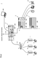
- Fig. 1 is a diagram for illustrating overview of processing in a control system 1 according to the present embodiment.
- a control device 2 is connected to one or more devices over a process network 10.
- a hub 8 may be arranged in process network 10.
- Control device 2 periodically performs a control operation for controlling an object to be controlled.
- Control device 2 performs communication processing for periodically exchanging data with the device. In other words, data is periodically exchanged between control device 2 and the device.
- control device 2 can determine a settable range of a cycle time (communication cycle time) of exchange of data with the device. Specifically, control device 2 calculates a settable communication cycle time in accordance with processing performed in control device 2 and settings involved with communication processing.
- Calculation of such a settable communication cycle time may be based on restriction factors as below.
- restriction factors may be determined based on contents set in a development environment provided by a support apparatus as will be described later and a settable communication cycle time may be calculated based on the determined restriction factors.
- the "settable range” is a term encompassing a range within which a value of interest can effectively be set, and may encompass not only a case in which both of an upper limit and a lower limit are defined but also a case in which only the lower limit or only the upper limit is defined. In particular in the present embodiment, attention is paid to determination of the lower limit (minimum value).
- Standard control and "safety control” are herein used in comparison to each other.
- Standard control is collective denotation of processing for controlling an object to be controlled in accordance with required specifications determined in advance.
- Safety control is collective denotation of processing for preventing human safety from being threatened by a facility or a machine.
- Safety control is designed to meet requirements for performing the safety function defined under IEC 61508.
- FIG. 2 is a schematic diagram showing an exemplary configuration of control system 1 according to the present embodiment.
- control system 1 includes control device 2, one or more remote IO apparatuses 4, and one or more slave devices, by way of example.
- Control device 2 is a processing entity that performs a control operation, and includes a standard control unit 100, a safety control unit 200, and one or more functional units 350.
- Standard control unit 100 performs a control operation involved with standard control and communication processing as will be described later.
- Safety control unit 200 performs a control operation involved with safety control.
- Each functional unit 350 performs processing in accordance with a function (for example, an input and output function, a position control function, a PID control function, etc.) implemented in each unit.
- Safety control unit 200 can also be regarded as a kind of functional unit 350.
- Standard control unit 100 is electrically connected to safety control unit 200 and functional unit 350 through an internal bus 18.
- Control device 2 (standard control unit 100) is electrically connected to remote IO apparatus 4 over a field network 6.
- Control device 2 is communicatively connected further to a safety driver 12 which is an exemplary slave device with process network 10 and hub 8 being interposed.
- Field network 6 is a communication medium for data transmission for factory automation (FA).
- a frame can be transmitted over field network 6 in each predetermined cycle time, and time of arrival of data at each node within the network is guaranteed.
- EtherCAT ® is adopted for field network 6 as an exemplary protocol under which such time of arrival of data is guaranteed.
- Data used for safety control as will be described later may be transmitted in conformity with functional safety over EtherCAT ® (FSoE) using EtherCAT ® .
- Process network 10 is a communication medium for data transmission for FA, similarly to field network 6.
- EtherNet/IP TM is adopted for process network 10.
- Data used for safety control as will be described later may be transmitted in conformity with CIP Safety using EtherNet/IP TM .
- Control device 2 (standard control unit 100) may further be connected to higher-order network 20.
- Any information processing apparatus such as a gateway or a database server may be connected to higher-order network 20.
- Remote IO apparatus 4 includes a coupler unit 300 and one or more functional units 350. Remote IO apparatus 4 collects various types of information from an object to be controlled and transmits them to control device 2, and provides a signal to the control device or performs processing in accordance with an instruction included in data from control device 2.
- Coupler unit 300 mediates data exchange between control device 2 (standard control unit 100) and functional unit 350. In addition, coupler unit 300 transmits data received in a frame to functional unit 350, and when coupler unit 300 receives data from functional unit 350, it prepares for storage of the received data in a frame that will arrive next.
- Functional unit 350 is substantially identical to functional unit 350 included in control device 2, and performs processing in accordance with a function (for example, an input and output function, a position control function, a PID control function, etc.) implemented in each unit.
- a function for example, an input and output function, a position control function, a PID control function, etc.
- Coupler unit 300 may also include a safety functional unit 360 by way of example of functional unit 350.
- Fig. 2 shows an example in which a single remote IO apparatus 4 includes safety functional unit 360.
- Safety functional unit 360 performs a function involved with safety control.
- safety functional unit 360 is a safety IO unit.
- the safety IO unit performs an input function to accept a signal from a safety component 16 such as an emergency stop button, a safety door switch, or a safety light curtain and/or an output function to provide a signal to safety component 16.
- Safety Control unit 200 may exchange data between safety control unit 200 and safety functional unit 360 in conformity with FSoE which represents a kind of peer-to-peer communication using a frame periodically transmitted over field network 6.
- FSoE represents a kind of peer-to-peer communication using a frame periodically transmitted over field network 6.
- Fig. 2 shows safety driver 12 that drives a motor 14 as a slave device.
- Safety driver 12 drives connected motor 14 in response to an instruction from control device 2 (standard control unit 100) and includes also a function as a safety component involved with drive of motor 14.
- Motor 14 is an arbitrary mobile body such as a servo motor, an induction motor, a synchronous motor, or a linear motor.
- Safety driver 12 exchanges data with control device 2 (standard control unit 100) by using connection established therebetween.
- control device 2 standard control unit 100
- CIP Safety is adopted as a protocol for exchange of data
- a support apparatus 500 is directed to control system 1, and provides a user with an environment for creation and debugging of a program to be executed in control device 2 (standard control unit 100 and safety control unit 200) and for support of various types of settings.
- control system 1 An exemplary hardware configuration of main apparatuses included in control system 1 will now be described.
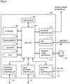
- Fig. 3 is a schematic diagram showing an exemplary hardware configuration of standard control unit 100 included in control system 1 according to the present embodiment.
- standard control unit 100 includes a processor 102, a chip set 104, a main memory 106, a storage 108, a network controller 110, a universal serial bus (USB) controller 112, a memory card interface 114, an internal bus controller 118, a field network controller 120, a process network controller 122, a counter 126, and a real time clock (RTC) 128.
- Processor 102 corresponds to a computing processing unit that performs a control operation or the like, and is configured with a central processing unit (CPU), a micro processing unit (MPU), or a graphics processing unit (GPU). Specifically, processor 102 performs an operation involved with standard control and communication processing as will be described later by reading a program (by way of example, a system program and a standard control program (a user program)) stored in storage 108, developing the program on main memory 106, and executing the program.
- Storage 108 is implemented, for example, by a non-volatile storage device such as a hard disk drive (HDD) or a solid state drive (SSD).
- Main memory 106 is implemented by a volatile storage device such as a dynamic random access memory (DRAM) or a static random access memory (SRAM).
- DRAM dynamic random access memory
- SRAM static random access memory
- Chip set 104 performs processing as standard control unit 100 as a whole by mediating data exchange between processor 102 and each device.
- a standard control program for realizing standard control created in conformity with an object to be controlled such as a facility or a machine is stored in storage 108.
- Network controller 110 exchanges data with an arbitrary information processing apparatus such as a gateway or a database server over higher-order network 20.
- USB controller 112 exchanges data with support apparatus 500 through USB connection.
- Memory card interface 114 is constructed such that a memory card 116 is attachable thereto and detachable therefrom, and allows writing of data into memory card 116 and reading of various types of data (a standard control program or trace data) from memory card 116.
- Internal bus controller 118 corresponds to a communication interface for electrical connection of standard control unit 100 to safety control unit 200 and functional unit 350 through internal bus 18. Internal bus controller 118 functions as a communication master for cyclic communication through internal bus 18.
- Field network controller 120 corresponds to a communication interface for electrical connection between standard control unit 100 and remote IO apparatus 4 over field network 6.
- Field network controller 120 functions as a communication master for cyclic communication over field network 6.
- Process network controller 122 corresponds to a communication interface for electrical connection between standard control unit 100 and safety driver 12 over process network 10.
- Process network controller 122 is responsible for communication control for exchange of data in each predetermined cycle time over process network 10.
- Counter 126 is used as time reference for managing timing of execution of various programs to be executed in standard control unit 100.
- RTC 128 is a kind of counter with a time counting function and provides current time to processor 102 or the like.
- Fig. 3 shows an exemplary configuration in which a necessary function is provided by execution of a program by processor 102
- a part or the entirety of these provided functions may be performed by using dedicated hardware circuitry (for example, an ASIC or an FPGA).
- a principal part of standard control unit 100 may be implemented by hardware (for example, an industrial personal computer based on a general-purpose personal computer) in accordance with a general-purpose architecture.
- a plurality of operating systems (OSs) different in application may be executed in parallel and a necessary application may be executed on each OS.
- OSs operating systems
- Fig. 4 is a schematic diagram showing an exemplary hardware configuration of safety control unit 200 included in control system 1 according to the present embodiment.
- safety control unit 200 includes an internal bus controller 218 and a main controller 210.
- Internal bus controller 218 corresponds to a communication interface for electrical connection between standard control unit 100 and safety control unit 200 through internal bus 18. Internal bus controller 218 functions as a communication slave for participating in data communication through internal bus 18.
- Main controller 210 includes a processor 202, a main memory 204, and a storage 208.
- Processor 202 corresponds to a computing processing unit that performs a control operation or communication processing and is configured with a CPU, an MPU, or a GPU. Specifically, processor 202 carries out safety control or the like by reading a safety program 220 stored in storage 208, developing the safety program on main memory 204, and executing the safety program.
- FIG. 4 shows an exemplary configuration in which a necessary function is provided by execution of a program by processor 202, a part or the entirety of these provided functions may be performed by using dedicated hardware circuitry (for example, an ASIC or an FPGA).
- dedicated hardware circuitry for example, an ASIC or an FPGA.
- Fig. 5 is a schematic diagram showing an exemplary hardware configuration of support apparatus 500 included in control system 1 according to the present embodiment.
- Support apparatus 500 is implemented by hardware (for example, a general-purpose personal computer) in accordance with a general-purpose architecture by way of example.
- support apparatus 500 includes a processor 502, a main memory 504, an input device 506, an output device 508, a storage 510, an optical drive 512, and a USB controller 520. These components are connected to one another through a processor bus 518.
- Processor 502 is configured with a CPU, an MPU, or a GPU, and performs various types of processing as will be described later by reading a program (an OS 5102 and a support program 5104 by way of example) stored in storage 510, developing the program on main memory 504, and executing the program.
- a program an OS 5102 and a support program 5104 by way of example
- Main memory 504 is implemented by a volatile storage device such as a DRAM or an SRAM Storage 510 is implemented by a non-volatile storage device such as an HDD or an SSD.
- support program 5104 for providing a function as support apparatus 500 is stored in storage 510.
- Support program 5104 provides a development environment for performing at least a part of creation of contents of processing performed by standard control unit 100 and making of settings involved with communication processing.
- project data 5106 created by a user in the development environment provided by execution of support program 5104 is stored in storage 510.
- Support apparatus 500 provides the development environment that allows, in an integrated manner, settings for each device included in control system 1 and creation of a program to be executed in each device.
- Project data 5106 includes data generated in such an integrated development environment.
- project data 5106 includes a standard control source program 5108, standard controller setting information 5110, a safety source program 5112, safety controller setting information 5114, and safety driver setting information 5116.
- Standard control source program 5108 is converted to an object code, then transmitted to standard control unit 100, and stored as a standard control program 1104. Similarly, standard controller setting information 5110 is also transmitted to standard control unit 100.
- Safety source program 5112 is converted to an object code, then transmitted to safety control unit 200, and stored as safety program 220 (see Fig. 4 ). Similarly, safety controller setting information 5114 is also transmitted to safety control unit 200.
- Safety driver setting information 5116 is transmitted to safety driver 12.
- Input device 506 is constituted of a keyboard, a mouse, and the like, and accepts an operation by a user.
- Output device 508 is constituted of a display, various indicators, a printer, and the like, and provides a result of processing from processor 502.
- USB controller 520 exchanges data with standard control unit 100 and the like through USB connection.
- Support apparatus 500 includes optical drive 512.
- a program stored in a recording medium 514 in which a computer readable program is stored in a non-transitory manner is read from the recording medium and installed in storage 510 or the like.
- an optical recording medium such as a digital versatile disc (DVD)
- support program 5104 and the like executed in support apparatus 500 may be installed from computer readable recording medium 514, it may be installed as being downloaded from a server apparatus over a network.
- a function provided by support apparatus 500 according to the present embodiment may be performed by using a part of a module provided by the OS.
- FIG. 5 shows an exemplary configuration in which a necessary function as support apparatus 500 is provided by execution of a program by processor 502, a part or the entirety of these provided functions may be performed by using dedicated hardware circuitry (for example, an ASIC or an FPGA).
- dedicated hardware circuitry for example, an ASIC or an FPGA.
- support apparatus 500 may be detached from standard control unit 100.
- Fig. 6 is a schematic diagram for illustrating FSoE in control system 1 according to the present embodiment.
- Fig. 6 shows an example in which data collected by safety functional unit 360 connected through a bus to coupler unit 300 is transmitted to safety control unit 200 in a configuration in which standard control unit 100 and coupler unit 300 are connected to each other over field network 6.
- Standard control unit 100 obtains input data collected by the functional unit through frames periodically transmitted over field network 6.
- Standard control unit 100 performs a control operation based on obtained input data and transmits in frames, a control instruction (output data) obtained by performing the control operation to the functional unit.
- standard control unit 100 periodically executes a control task 150 in correspondence with a frame transmission cycle time over field network 6.
- standard control unit 100 implementing control device 2 periodically performs a control operation for controlling an object to be controlled.
- IO refresh processing 152 In each cycle of execution (task cycle time) of control task 150, IO refresh processing 152, user program execution processing 154 such as a sequence operation, motion program execution processing 156, and the like is performed.
- IO refresh processing 152 is processing for updating data included in a frame transmitted over field network 6 to a state that can be referred to in standard control unit 100.
- the frame transmission cycle time is normally set to coincide with the task cycle time in standard control unit 100.
- Standard control unit 100 mediates data for implementing FSoE.
- Processing for transferring data transmitted over field network 6 to safety control unit 200 and processing for storing data transmitted from safety control unit 200 in frames and sending the frames over field network 6 is performed as a part of IO refresh processing 152 included in control task 150.
- FSoE data loopback processing is performed as a part of IO refresh processing 152, responsiveness of FSoE can be secured.
- a time period required for exchange of data in conformity with FSoE is guaranteed as a time period determined in accordance with the task cycle time (that is, the transmission cycle time).
- Fig. 7 is a schematic diagram for illustrating CIP Safety in control system 1 according to the present embodiment.
- Fig. 7 shows an example in which data is exchanged between safety control unit 200 and safety driver 12 in a configuration in which standard control unit 100 and safety driver 12 representing an exemplary slave device are connected to each other over process network 10.
- a frame (a CIP Safety frame) is exchanged for each connection defined in advance between standard control unit 100 and each slave device (safety driver 12 in the example shown in Fig. 7 ).
- An expected packet interval (EPI) is set in advance as a cycle time within which exchange of a frame for each connection can be completed.
- EPI expected packet interval
- all CIP Safety frames corresponding to each connection are generated and transmitted at least once within a corresponding EPI.
- the EPI may be defined for each communication counterpart device (target device).
- Standard control unit 100 transfers a frame received from each slave device to safety control unit 200 through internal bus 18.
- standard control unit 100 functions as a bridge that mediates frame transfer between each slave device and safety control unit 200.
- the function as the bridge is performed as communication processing 160 independent of control task 150.
- a CIP Safety communication service 162 for processing a CIP Safety frame in conformity with CIP Safety is performed.
- Fig. 8 is a schematic diagram showing an exemplary functional configuration for implementing CIP Safety in control device 2 according to the present embodiment.
- control device 2 includes CIP Safety communication service 162, a CIP Safety protocol stack 164, and a safety control executer 250 as functions in connection with CIP Safety.
- CIP Safety communication service 162 corresponds to a processing module configured to process a CIP Safety frame. Specifically, CIP Safety communication service 162 receives a CIP Safety frame from a slave device and provides the received CIP Safety frame to CIP Safety protocol stack 164. CIP Safety communication service 162 transmits the CIP Safety frame to a destination slave device in response to an instruction from CIP Safety protocol stack 164.
- CIP Safety protocol stack 164 manages exchange of a CIP Safety frame in conformity with CIP Safety. Specifically, CIP Safety protocol stack 164 analyzes the provided CIP Safety frame and provides data (input data) included therein to safety control executer 250. CIP Safety protocol stack 164 generates a CIP Safety frame in accordance with a control instruction (output data) from safety control executer 250 and provides the CIP Safety frame to CIP Safety communication service 162.
- Safety control executer 250 calculates a control instruction (output data) by performing a control operation involved with safety control based on the input data from CIP Safety protocol stack 164.
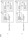
- Fig. 9 is a schematic diagram showing an exemplary implementation of the functional configuration shown in Fig. 8 .
- Fig. 9 (a) shows an exemplary configuration including standard control unit 100 and safety control unit 200.
- CIP Safety communication service 162 is implemented in standard control unit 100
- CIP Safety protocol stack 164 and safety control executer 250 are implemented in safety control unit 200.
- Fig. 9 (b) shows an exemplary configuration in which all functions are implemented in safety control unit 200.
- CIP Safety communication service 162, CIP Safety protocol stack 164, and safety control executer 250 are implemented in safety control unit 200.
- Standard control unit 100 or safety control unit 200 that implements control device 2 thus performs communication processing for periodically exchanging data with a slave device.
- a shorter EPI means a shorter cycle time of update of data. Therefore, in consideration of control performance or the like, the EPI preferably as short as possible is set.
- a settable EPI is determined under restrictions as shown below.
- a settable range of the EPI is determined based on at least one of such restriction factors.
- Each restriction factor will be described below.
- control system 1 Various types of settings for a unit that affect responsiveness of CIP Safety include each cycle time of execution (task cycle time) of control task 150. Therefore, in control system 1 according to the present embodiment, the settable range of the EPI may be determined based on a cycle time (task cycle time) of a control operation performed in standard control unit 100.
- Contents of settings for CIP Safety include the number of connections and a data size in CIP Safety.
- the number of connections in CIP Safety may include both of the number of connections (the maximum number) specifically supported by control system 1 and the number of connections arbitrarily set by a user.
- the data size in CIP Safety may encompass both of a size of data allocated to each connection and total data allocated to all connections.
- Fig. 10 is a schematic diagram for illustrating exemplary contents of settings for CIP Safety in control device 2 according to the present embodiment.
- Fig. 10 (a) shows an example in which connections C1 to C100 are set and
- Fig. 10 (b) shows an example in which connections C1 to C10 are set.
- the settable range of the EPI may be determined based on at least one of the number of connections and a data size of data exchanged with a slave device.
- the EPI can also be defined for each target device.
- the settable range of the EPI may be determined for each device with which control device 2 exchanges data.
- Processing capability (spec) of a unit that provides CIP Safety communication service 162 means hardware performance of a unit (standard control unit 100 or safety control unit 200 as shown in Fig. 9 ) in which CIP Safety communication service 162 is implemented. Such processing capability (spec) is dependent on performance of a processor mounted on the unit, a memory capacity, a data transmission rate, and the like.
- control system 1 the settable range of the EPI may be determined based on processing capability of control device 2 (standard control unit 100 and safety control unit 200).
- Fig. 11 is a schematic diagram for illustrating exemplary execution of the CIP Safety communication service in control device 2 according to the present embodiment.
- Fig. 11 shows exemplary execution in the unit (standard control unit 100 or safety control unit 200) that provides CIP Safety communication service 162.
- a common resource is used to perform a service X 166 and a service Y 167 in addition to CIP Safety communication service 162.
- Fig. 11 (a) shows an example in which CIP Safety communication service 162 is performed with priority higher than other services being placed thereon
- Fig. 11 (b) shows an example in which CIP Safety communication service 162 is performed with priority lower than other services being placed thereon.
- CIP Safety communication service 162 when CIP Safety communication service 162 is higher in priority than other services as shown in Fig. 11 (a) , the EPI can be shorter because CIP Safety communication service 162 is preferentially performed.
- Responsiveness (that is, the minimum value of the EPI) of CIP Safety thus varies depending on contents of the service performed in the unit that provides CIP Safety communication service 162 and the priority defined for each service. Therefore, in control system 1 according to the present embodiment, the settable range of the EPI may be determined based on the priority defined for a control operation performed in standard control unit 100.
- activation or inactivation of execution can be set in advance. At least one of services, however, cannot be inactivated, and execution thereof may be fixed.
- the priority in the unit that provides CIP Safety communication service 162 can arbitrarily be set.
- the priority of at least one of services may also be set to a designed value.
- the settable range of the EPI may be determined with both of the restriction factor (by way of example, (1), (4-1), and (4-2) described above) determined in accordance with contents of processing performed by standard control unit 100 and safety control unit 200 that implement control device 2 and the restriction factor (by way of example, (2) described above) determined in accordance with settings involved with communication processing being reflected.
- Control device 1 can also provide a function to support settings of responsiveness (the length of the EPI) of CIP Safety with the restriction factors as described above being reflected.
- the function to support settings of responsiveness (the length of the EPI) of CIP Safety will be described below.
- control system 1 can automatically calculate a minimum value of the settable EPI determined in accordance with performance of the unit and current settings.
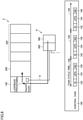
- Fig. 12 is a diagram showing an exemplary parameter table 170 used for calculating a minimum value of the EPI settable in control system 1 according to the present embodiment.
- parameter table 170 includes parameter values including a first parameter 172, a second parameter 174, and a third parameter group 176 for each type of a controller (typically, standard control unit 100) by way of example.
- First parameter 172 reflects a restriction factor for "(1) Various types of settings for unit that affect responsiveness of CIP Safety.”
- Second parameter 174 reflects a restriction factor for "(2) Contents of settings for CIP Safety.”
- Third parameter group 176 reflects a restriction factor for "(4-1) Other services provided by unit that provides CIP Safety communication service 162" and "(4-2) Priority in unit that provides CIP Safety communication service 162.”
- First parameter 172, second parameter 174, and third parameter group 176 each reflect the restriction factor for "(3) Processing capability (spec) of unit that provides CIP Safety communication service 162.”
- a set value Ts represents each cycle time (task cycle time) of execution of control task 150.
- set value Ts means an IO refresh cycle time.
- a set value Sc represents the number of connections of CIP Safety.
- a data size of CIP Safety may be employed as set value Sc.
- Parameter values (parameter values c, d, and e) in third parameter group 176 reflect a service to be performed, priority, and the like. Therefore, when the service performed in the controller of interest or the priority is changed, the minimum value of the settable EPI may be calculated again in accordance with the changed contents of settings.
- Fig. 13 is a diagram for illustrating processing for calculating again the minimum value of the EPI settable in control system 1 according to the present embodiment. Referring to Fig. 13 , when contents of the service performed in the controller of interest or the priority defined for the service are/is changed, an applied parameter may be selected again and the minimum value of the settable EPI may be calculated again.
- priority of CIP Safety communication service 162 is highest next to service X 166.
- Service Y 167 and a service Z 168 are lower in priority than CIP Safety communication service 162.
- a predetermined value may be set as the maximum value of the EPI.
- any value smaller than a time period on which determination as a communication error (time-out) is based may be set as the maximum value of the EPI.
- a function to calculate the minimum value of the settable EPI as described above is typically implemented in support apparatus 500.
- a functional configuration in an implementation in support apparatus 500 will be described below.
- Fig. 14 is a block diagram showing an exemplary functional configuration of support apparatus 500 included in control system 1 according to the present embodiment.
- a main function shown in Fig. 14 is performed by execution of support program 5104 by processor 502 of support apparatus 500 ( Fig. 5 ).
- support apparatus 500 includes a program developer 540 and an EPI calculator 550.
- Program developer 540 provides an interface for developing a program to be executed in control device 2 and for making necessary settings.
- Program developer 540 generates project data 5106 (see Fig. 5 or the like) including standard control source program 5108, standard controller setting information 5110, safety source program 5112, safety controller setting information 5114, and safety driver setting information 5116, in accordance with an operation by a user.
- Program developer 540 thus provides a development environment for performing at least a part of creation of contents of processing performed by standard control unit 100 and safety control unit 200 that implement control device 2 and making of settings involved with communication processing.
- EPI calculator 550 calculates the minimum value of the settable EPI based on setting information 542 (including standard controller setting information 5110 and safety controller setting information 5114) generated by program developer 540 and parameter table 170 (see Fig. 12 ).
- the minimum value of the settable EPI calculated by EPI calculator 550 may be presented to a user through output device 508 (see Fig. 5 and the like) such as a display.
- EPI calculator 550 thus determines a settable range of a cycle time (EPI) of exchange of data with a slave device based on contents set in the development environment provided by program developer 540.
- EPI cycle time
- An exemplary user interface screen for presenting to a user, a result of calculation of the minimum value of the settable EPI as described above will now be described.
- Fig. 15 is a diagram showing an exemplary user interface screen provided by control system 1 according to the present embodiment.
- a user interface screen 570 shown in Fig. 15 may typically be shown on support apparatus 500.
- user interface screen 570 includes an EPI settable range 572 brought in correspondence with setting information 574.
- Setting information 574 includes a task cycle time 575 (setting Ts), the number of connections 576 (setting Sc), and type information 577 as setting items.
- Support apparatus 500 thus calculates the minimum value of the settable EPI and presents the minimum value to the user, together with setting information corresponding to calculation of the EPI.
- Fig. 16 is a diagram showing another exemplary user interface screen provided by control system 1 according to the present embodiment.
- a current EPI set value 582 is shown for each target device 588.
- Setting information 584 (a task cycle time 585 (setting Ts), the number of connections 586 (setting Sc), and type information 587) is shown in correspondence with EPI set value 582 for each target device 588.
- EPI set value 582 When EPI set value 582 is smaller than the minimum value of the settable EPI calculated based on corresponding setting information 584 (that is, out of the settable range), an error may be presented to the user.
- the error may be presented in any form, and for example, such a manner that a color of a character or a background of corresponding EPI set value 582 is different from that in a normal manner of representation may be adopted.
- Fig. 16 shows an example in which an attention representation 589 for presenting an error is given for EPI set value 582.
- corresponding EPI set value 582 may blink or an audio notification may be given.
- a message 579 that suggests change of contents of settings in setting information 584 may be shown such that the EPI is within the settable range.
- a message indicating that EPI set value 582 can be within the settable range by reducing the number of connections 586 (setting Sc) is presented.
- Contents included in message 579 that suggest change of contents of settings are determined by generation by support apparatus 500, of some candidates different in setting information 584 and calculation of the minimum value of the settable EPI for each candidate.
- Fig. 17 is a diagram showing yet another exemplary user interface screen provided by control system 1 according to the present embodiment.
- a user interface screen 590 shown in Fig. 17 provides an interface for making settings involved with CIP Safety.
- User interface screen 590 includes information on connection defined for a port to be set.
- user interface screen 590 includes a flag 592 for selecting activation or inactivation of settings of connection, setting 593 of data allocated to connection of interest, a minimum value 594 of the corresponding settable EPI, and a time period 596 for network response to a communication counterpart device (target device).
- Time period 596 for network response may be set to a value calculated by simulation or a value obtained by actual measurement (an actually measured value).
- an error message 595 including the settable range may be shown.
- support apparatus 500 may perform a notification function to give a notification when a set value of a cycle time of exchange of data with a slave device is out of the settable range of the EPI.
- Fig. 18 is a flowchart showing an exemplary procedure of processing performed in support apparatus 500 included in control system 1 according to the present embodiment. Each step shown in Fig. 18 is performed by execution of support program 5104 by processor 502 of support apparatus 500 ( Fig. 5 ).
- support apparatus 500 starts providing the development environment in response to an operation by a user (step S100). Specifically, support apparatus 500 performs processing for providing the development environment for performing at least a part of creation of contents of processing performed by standard control unit 100 and making of settings involved with communication processing.
- Support apparatus 500 generates a program and determines various types of setting information in response to an operation by the user (step S102). Then, support apparatus 500 determines whether or not information necessary for calculation of the minimum value of the settable EPI is ready (step S104). When information necessary for calculation of the minimum value of the settable EPI is not ready (NO in step S104), support apparatus 500 repeats processing in step S102 or later.
- support apparatus 500 selects one device (target device) of interest of calculation (step S106) and calculates the minimum value of the settable EPI based on relevant setting information (step S108). In other words, support apparatus 500 performs processing for determining the settable range of the EPI which is a cycle time of exchange of data with a slave device, based on contents set in the development environment.
- support apparatus 500 determines whether or not the minimum value of the settable EPI has been calculated for all devices of interest of calculation (step S110). When there remains a device for which the minimum value of the settable EPI has not been calculated (NO in step S110), support apparatus 500 repeats processing in step S106 or later.
- support apparatus 500 determines whether or not there is an EPI smaller in minimum value of the corresponding settable EPI among one or more currently set EPIs (step S112).
- support apparatus 500 specifies the EPI smaller in minimum value of the settable EPI (step S114).
- processing in step S114 is skipped.
- support apparatus 500 presents to a user, the calculated minimum value of the settable EPI and an error for the EPI smaller in minimum value of the settable EPI (step S116). Then, the process ends.
- support apparatus 500 calculates the minimum value of the settable EPI
- any processing entity can calculate the minimum value of the settable EPI.
- a controller standard control unit 100 or safety control unit 200
- a computer arranged on a cloud may calculate the minimum value of the EPI based on setting information provided from support apparatus 500.
- any processing entity may perform the method of calculating the minimum value of the settable EPI according to the present embodiment.
- CIP Safety is mainly described in detail in the description above. Without being limited to CIP Safety, however, the present invention is widely applicable to data communication in which data of a predetermined data size is periodically exchanged with one or more communication counterparts. For example, the present invention is applicable to normal frame transmission in conformity with EtherNet/IP TM .
- Control device 2 including standard control unit 100 and safety control unit 200 independent of each other is exemplified in the description above. Without being limited to such a configuration, however, a single controller in which functions of both of these units are integrated may be implemented. Since the essence of the present invention resides in communication processing, control device 2 including both of standard control unit 100 and safety control unit 200 does not necessarily have to be employed but the control device may be configured to include only any one of the units.
- the determination means is configured to determine the settable range with both of a restriction factor determined in accordance with the contents of processing performed by the control means and a restriction factor determined in accordance with settings involved with communication processing by the communication processing means being reflected.
- control system described in Aspect 1 or 2 wherein the determination means is configured to determine the settable range based on at least one of the number of connections and a data size of data exchanged with the device.
- control system described in any one of Aspects 1 to 3, wherein the determination means is configured to determine the settable range based on a cycle time of the control operation performed by the control means.
- control system described in any one of Aspects 1 to 4, wherein the determination means is configured to determine the settable range based on priority defined for the control operation performed by the control means.
- control system described in any one of Aspects 1 to 5, wherein the determination means is configured to determine the settable range based on processing capability of the control device.
- control system described in any one of Aspects 1 to 6, wherein the determination means is configured to determine the settable range for each device with which the control device exchanges data.
- control system described in any one of Aspects 1 to 7, further comprising notification means (500) configured to give a notification when a set value of the cycle time of exchange of data with the device is out of the settable range determined by the determination means.
- a settable range of a cycle time (EPI) of exchange of data between control device 2 and a slave device can be determined based on contents of processing performed in control device 2 and settings involved with communication processing. Therefore, even a user with less knowledge can set an appropriate cycle time. Thus, occurrence of failure such as communication disconnection due to expiration of the cycle time can be prevented in control devices of various types that are variously set depending on an object to be controlled.
- EPI cycle time
- the settable range of the cycle time (EPI) of exchange of data can be known in advance, and hence apparatus design can readily be made.
Landscapes
- Engineering & Computer Science (AREA)
- Physics & Mathematics (AREA)
- General Physics & Mathematics (AREA)
- Automation & Control Theory (AREA)
- Computer Networks & Wireless Communication (AREA)
- Signal Processing (AREA)
- Programmable Controllers (AREA)
Abstract
Description
- The present invention relates to a control system configured to periodically exchange data, a support apparatus, and a program for a support apparatus.
- A programmable logic controller (PLC) is employed as a control device configured to control a facility or a machine. In addition to the PLC, a safety system including a safety controller and various safety components may also be arranged.
- With advance of information and communication technology (ICT), such an industrial controller has also increasingly been networked. In a known configuration, as disclosed, for example, in PTL 1 (
Japanese Patent Laying-Open No. 2009-223398 Japanese Patent Laying-Open No. 2017-027539 -
- PTL 1:
Japanese Patent Laying-Open No. 2009-223398 - PTL 2:
Japanese Patent Laying-Open No. 2017-027539 - Normally, in a control operation for controlling an object to be controlled such as a facility or a machine, input and output data (IO data) should periodically be updated. In order to periodically update such IO data, data should periodically be exchanged with a device from which IO data is collected.
- In periodically exchanging data over a network, however, there are various restriction factors, and it is not easy to determine to which value a communication cycle time should be set.
- An object of the present invention is to provide a configuration in which a settable range of a cycle time of exchange of data with a device can readily be determined.
- According to one embodiment of the present invention, a control system including a control device and a device configured to communicate with the control device is provided. The control system includes control means configured to periodically perform a control operation for controlling an object to be controlled, communication processing means configured to perform communication processing for periodically exchanging data with the device, providing means configured to provide a development environment for performing at least a part of creation of contents of processing performed by the control means and making of settings involved with communication processing by the communication processing means, and determination means configured to determine a settable range of a cycle time of exchange of data with the device based on contents set in the development environment provided by the providing means.
- According to this embodiment, since the settable range of the cycle time of exchange of data with the device is determined based on contents of processing performed by the control means and settings involved with communication processing, even a user with less knowledge can set an appropriate cycle time.
- The determination means may determine the settable range with both of a restriction factor determined in accordance with the contents of processing performed by the control means and a restriction factor determined in accordance with settings involved with communication processing by the communication processing means being reflected. According to this configuration, an appropriate range on which both of the restriction factor determined in accordance with contents of processing performed by the control means and the restriction factor determined in accordance with settings involved with communication processing by the communication processing means are reflected can be determined.
- The determination means may determine the settable range based on at least one of the number of connections and a data size of data exchanged with the device. According to this configuration, an appropriate range can be determined in accordance with data exchanged with the device.
- The determination means may determine the settable range based on a cycle time of the control operation performed by the control means. According to this configuration, an appropriate range can be determined in accordance with the cycle time of the control operation.
- The determination means may determine the settable range based on priority defined for the control operation performed by the control means. According to this configuration, an appropriate range can be determined in accordance with priority defined for the control operation.
- The determination means may determine the settable range based on processing capability of the control device. According to this configuration, an appropriate range can be determined in accordance with processing capability of the control device.
- The determination means may determine the settable range for each device with which the control device exchanges data. According to this configuration, when data is exchanged with a plurality of devices, a range appropriate for each device can be determined.
- Notification means configured to give a notification when a set value of the cycle time of exchange of data with the device is out of the settable range determined by the determination means may further be included. According to this configuration, when a currently set value is out of the settable range of the cycle time, a user can be prompted to make appropriate change.
- According to another embodiment of the present invention, a support apparatus directed to a control system including a control device and a device configured to communicate with the control device is provided. The control device includes control means configured to periodically perform a control operation for controlling an object to be controlled and communication processing means configured to perform communication processing for periodically exchanging data with the device. The support apparatus includes providing means configured to provide a development environment for performing at least a part of creation of contents of processing performed by the control means and making of settings involved with communication processing by the communication processing means and determination means configured to determine a settable range of a cycle time of exchange of data with the device based on contents set in the development environment provided by the providing means.
- According to yet another embodiment of the present invention, a program for a support apparatus directed to a control system including a control device and a device configured to communicate with the control device is provided. The control device includes control means configured to periodically perform a control operation for controlling an object to be controlled and communication processing means configured to perform communication processing for periodically exchanging data with the device. The program, when executed by a computer, causes the computer to perform providing a development environment for performing at least a part of creation of contents of processing performed by the control means and making of settings involved with communication processing by the communication processing means and determining a settable range of a cycle time of exchange of data with the device based on contents set in the development environment.
- According to the present invention, a settable range of a cycle time of exchange of data with a device can readily be determined.
-
-
Fig. 1 is a diagram for illustrating overview of processing in a control system according to the present embodiment. -
Fig. 2 is a schematic diagram showing an exemplary configuration of the control system according to the present embodiment. -
Fig. 3 is a schematic diagram showing an exemplary hardware configuration of a standard control unit included in the control system according to the present embodiment. -
Fig. 4 is a schematic diagram showing an exemplary hardware configuration of a safety control unit included in the control system according to the present embodiment. -
Fig. 5 is a schematic diagram showing an exemplary hardware configuration of a support apparatus included in the control system according to the present embodiment. -
Fig. 6 is a schematic diagram for illustrating FSoE in the control system according to the present embodiment. -
Fig. 7 is a schematic diagram for illustrating CIP Safety in the control system according to the present embodiment. -
Fig. 8 is a schematic diagram showing an exemplary functional configuration for implementing CIP Safety in a control device according to the present embodiment. -
Fig. 9 is a schematic diagram showing an exemplary implementation of the functional configuration shown inFig. 8 . -
Fig. 10 is a schematic diagram for illustrating exemplary contents of settings for CIP Safety in the control device according to the present embodiment. -
Fig. 11 is a schematic diagram for illustrating exemplary execution of a CIP Safety communication service in the control device according to the present embodiment. -
Fig. 12 is a diagram showing an exemplary parameter table used for calculating a minimum value of an EPI settable in the control system according to the present embodiment. -
Fig. 13 is a diagram for illustrating processing for calculating again, the minimum value of the EPI settable in the control system according to the present embodiment. -
Fig. 14 is a block diagram showing an exemplary functional configuration of the support apparatus included in the control system according to the present embodiment. -
Fig. 15 is a diagram showing an exemplary user interface screen provided by the control system according to the present embodiment. -
Fig. 16 is a diagram showing another exemplary user interface screen provided by the control system according to the present embodiment. -
Fig. 17 is a diagram showing yet another exemplary user interface screen provided by the control system according to the present embodiment. -
Fig. 18 is a flowchart showing an exemplary procedure of processing performed in the support apparatus included in the control system according to the present embodiment. - An embodiment of the present invention will be described in detail with reference to the drawings. The same or corresponding elements in the drawings have the same reference characters allotted and description thereof will not be repeated.
- An exemplary scene to which the present invention is applied will initially be described with reference to
Fig. 1 . -
Fig. 1 is a diagram for illustrating overview of processing in acontrol system 1 according to the present embodiment. Referring toFig. 1 , acontrol device 2 is connected to one or more devices over aprocess network 10. Ahub 8 may be arranged inprocess network 10. -
Control device 2 periodically performs a control operation for controlling an object to be controlled.Control device 2 performs communication processing for periodically exchanging data with the device. In other words, data is periodically exchanged betweencontrol device 2 and the device. - In consideration of such communication processing,
control device 2 can determine a settable range of a cycle time (communication cycle time) of exchange of data with the device. Specifically,control device 2 calculates a settable communication cycle time in accordance with processing performed incontrol device 2 and settings involved with communication processing. - Calculation of such a settable communication cycle time may be based on restriction factors as below.
- Various types of settings for control device (unit)
- Contents of settings for communication
- Processing capability (spec) of control device (unit)
- Other services provided by control device (unit)
- Priority in control device (unit)
- Such restriction factors may be determined based on contents set in a development environment provided by a support apparatus as will be described later and a settable communication cycle time may be calculated based on the determined restriction factors.
- The "settable range" is a term encompassing a range within which a value of interest can effectively be set, and may encompass not only a case in which both of an upper limit and a lower limit are defined but also a case in which only the lower limit or only the upper limit is defined. In particular in the present embodiment, attention is paid to determination of the lower limit (minimum value).
- Principal data transmitted and received between the control device and each device is herein described as a "frame". Transmitted and received data, however, should not be interpreted as being limited by the term "frame", but for example, a case in which data is transmitted and received in a unit of a "packet" or a case in which data is transmitted and received in a unit of a data string that is longer may also be encompassed.
- The terms "standard control" and "safety control" are herein used in comparison to each other. "Standard control" is collective denotation of processing for controlling an object to be controlled in accordance with required specifications determined in advance. "Safety control" is collective denotation of processing for preventing human safety from being threatened by a facility or a machine. "Safety control" is designed to meet requirements for performing the safety function defined under IEC 61508.
- An exemplary configuration of
control system 1 according to the present embodiment will initially be described.Fig. 2 is a schematic diagram showing an exemplary configuration ofcontrol system 1 according to the present embodiment. - Referring to
Fig. 2 ,control system 1 includescontrol device 2, one or moreremote IO apparatuses 4, and one or more slave devices, by way of example. -
Control device 2 is a processing entity that performs a control operation, and includes astandard control unit 100, asafety control unit 200, and one or morefunctional units 350.Standard control unit 100 performs a control operation involved with standard control and communication processing as will be described later.Safety control unit 200 performs a control operation involved with safety control. Eachfunctional unit 350 performs processing in accordance with a function (for example, an input and output function, a position control function, a PID control function, etc.) implemented in each unit.Safety control unit 200 can also be regarded as a kind offunctional unit 350. -
Standard control unit 100 is electrically connected tosafety control unit 200 andfunctional unit 350 through aninternal bus 18. - Control device 2 (standard control unit 100) is electrically connected to
remote IO apparatus 4 over afield network 6.Control device 2 is communicatively connected further to asafety driver 12 which is an exemplary slave device withprocess network 10 andhub 8 being interposed. -
Field network 6 is a communication medium for data transmission for factory automation (FA). A frame can be transmitted overfield network 6 in each predetermined cycle time, and time of arrival of data at each node within the network is guaranteed. Incontrol system 1 according to the present embodiment, EtherCAT® is adopted forfield network 6 as an exemplary protocol under which such time of arrival of data is guaranteed. Data used for safety control as will be described later may be transmitted in conformity with functional safety over EtherCAT® (FSoE) using EtherCAT®. -
Process network 10 is a communication medium for data transmission for FA, similarly tofield network 6. Incontrol system 1 according to the present embodiment, EtherNet/IP™ is adopted forprocess network 10. Data used for safety control as will be described later may be transmitted in conformity with CIP Safety using EtherNet/IP™. - Control device 2 (standard control unit 100) may further be connected to higher-
order network 20. Any information processing apparatus such as a gateway or a database server may be connected to higher-order network 20. -
Remote IO apparatus 4 includes acoupler unit 300 and one or morefunctional units 350.Remote IO apparatus 4 collects various types of information from an object to be controlled and transmits them to controldevice 2, and provides a signal to the control device or performs processing in accordance with an instruction included in data fromcontrol device 2. -
Coupler unit 300 mediates data exchange between control device 2 (standard control unit 100) andfunctional unit 350. In addition,coupler unit 300 transmits data received in a frame tofunctional unit 350, and whencoupler unit 300 receives data fromfunctional unit 350, it prepares for storage of the received data in a frame that will arrive next. -
Functional unit 350 is substantially identical tofunctional unit 350 included incontrol device 2, and performs processing in accordance with a function (for example, an input and output function, a position control function, a PID control function, etc.) implemented in each unit. -
Coupler unit 300 may also include a safetyfunctional unit 360 by way of example offunctional unit 350.Fig. 2 shows an example in which a singleremote IO apparatus 4 includes safetyfunctional unit 360. Safetyfunctional unit 360 performs a function involved with safety control. By way of example, safetyfunctional unit 360 is a safety IO unit. The safety IO unit performs an input function to accept a signal from asafety component 16 such as an emergency stop button, a safety door switch, or a safety light curtain and/or an output function to provide a signal tosafety component 16. - Data may be exchanged between
safety control unit 200 and safetyfunctional unit 360 in conformity with FSoE which represents a kind of peer-to-peer communication using a frame periodically transmitted overfield network 6. -
Fig. 2 showssafety driver 12 that drives amotor 14 as a slave device.Safety driver 12 drives connectedmotor 14 in response to an instruction from control device 2 (standard control unit 100) and includes also a function as a safety component involved with drive ofmotor 14.Motor 14 is an arbitrary mobile body such as a servo motor, an induction motor, a synchronous motor, or a linear motor. -
Safety driver 12 exchanges data with control device 2 (standard control unit 100) by using connection established therebetween. An example in which CIP Safety is adopted as a protocol for exchange of data will be described below. - A
support apparatus 500 is directed to controlsystem 1, and provides a user with an environment for creation and debugging of a program to be executed in control device 2 (standard control unit 100 and safety control unit 200) and for support of various types of settings. - An exemplary hardware configuration of main apparatuses included in
control system 1 will now be described. -
Fig. 3 is a schematic diagram showing an exemplary hardware configuration ofstandard control unit 100 included incontrol system 1 according to the present embodiment. Referring toFig. 3 ,standard control unit 100 includes aprocessor 102, achip set 104, amain memory 106, astorage 108, anetwork controller 110, a universal serial bus (USB)controller 112, amemory card interface 114, aninternal bus controller 118, afield network controller 120, aprocess network controller 122, acounter 126, and a real time clock (RTC) 128. -
Processor 102 corresponds to a computing processing unit that performs a control operation or the like, and is configured with a central processing unit (CPU), a micro processing unit (MPU), or a graphics processing unit (GPU). Specifically,processor 102 performs an operation involved with standard control and communication processing as will be described later by reading a program (by way of example, a system program and a standard control program (a user program)) stored instorage 108, developing the program onmain memory 106, and executing the program.Storage 108 is implemented, for example, by a non-volatile storage device such as a hard disk drive (HDD) or a solid state drive (SSD).Main memory 106 is implemented by a volatile storage device such as a dynamic random access memory (DRAM) or a static random access memory (SRAM). - Chip set 104 performs processing as
standard control unit 100 as a whole by mediating data exchange betweenprocessor 102 and each device. - In addition to a system program for performing a basic function, a standard control program for realizing standard control created in conformity with an object to be controlled such as a facility or a machine is stored in
storage 108. -
Network controller 110 exchanges data with an arbitrary information processing apparatus such as a gateway or a database server over higher-order network 20. -
USB controller 112 exchanges data withsupport apparatus 500 through USB connection. -
Memory card interface 114 is constructed such that amemory card 116 is attachable thereto and detachable therefrom, and allows writing of data intomemory card 116 and reading of various types of data (a standard control program or trace data) frommemory card 116. -
Internal bus controller 118 corresponds to a communication interface for electrical connection ofstandard control unit 100 tosafety control unit 200 andfunctional unit 350 throughinternal bus 18.Internal bus controller 118 functions as a communication master for cyclic communication throughinternal bus 18. -
Field network controller 120 corresponds to a communication interface for electrical connection betweenstandard control unit 100 andremote IO apparatus 4 overfield network 6.Field network controller 120 functions as a communication master for cyclic communication overfield network 6. -
Process network controller 122 corresponds to a communication interface for electrical connection betweenstandard control unit 100 andsafety driver 12 overprocess network 10.Process network controller 122 is responsible for communication control for exchange of data in each predetermined cycle time overprocess network 10. -
Counter 126 is used as time reference for managing timing of execution of various programs to be executed instandard control unit 100.RTC 128 is a kind of counter with a time counting function and provides current time toprocessor 102 or the like. - Though
Fig. 3 shows an exemplary configuration in which a necessary function is provided by execution of a program byprocessor 102, a part or the entirety of these provided functions may be performed by using dedicated hardware circuitry (for example, an ASIC or an FPGA). Alternatively, a principal part ofstandard control unit 100 may be implemented by hardware (for example, an industrial personal computer based on a general-purpose personal computer) in accordance with a general-purpose architecture. In this case, using virtualization technology, a plurality of operating systems (OSs) different in application may be executed in parallel and a necessary application may be executed on each OS. A configuration in which a function of a display apparatus or a support apparatus is incorporated instandard control unit 100 may be adopted. -
Fig. 4 is a schematic diagram showing an exemplary hardware configuration ofsafety control unit 200 included incontrol system 1 according to the present embodiment. Referring toFig. 4 ,safety control unit 200 includes aninternal bus controller 218 and amain controller 210. -
Internal bus controller 218 corresponds to a communication interface for electrical connection betweenstandard control unit 100 andsafety control unit 200 throughinternal bus 18.Internal bus controller 218 functions as a communication slave for participating in data communication throughinternal bus 18. -
Main controller 210 includes aprocessor 202, amain memory 204, and astorage 208.Processor 202 corresponds to a computing processing unit that performs a control operation or communication processing and is configured with a CPU, an MPU, or a GPU. Specifically,processor 202 carries out safety control or the like by reading asafety program 220 stored instorage 208, developing the safety program onmain memory 204, and executing the safety program. - Though
Fig. 4 shows an exemplary configuration in which a necessary function is provided by execution of a program byprocessor 202, a part or the entirety of these provided functions may be performed by using dedicated hardware circuitry (for example, an ASIC or an FPGA). -
Fig. 5 is a schematic diagram showing an exemplary hardware configuration ofsupport apparatus 500 included incontrol system 1 according to the present embodiment.Support apparatus 500 is implemented by hardware (for example, a general-purpose personal computer) in accordance with a general-purpose architecture by way of example. - Referring to
Fig. 5 ,support apparatus 500 includes aprocessor 502, amain memory 504, aninput device 506, anoutput device 508, astorage 510, anoptical drive 512, and aUSB controller 520. These components are connected to one another through aprocessor bus 518. -
Processor 502 is configured with a CPU, an MPU, or a GPU, and performs various types of processing as will be described later by reading a program (anOS 5102 and asupport program 5104 by way of example) stored instorage 510, developing the program onmain memory 504, and executing the program. -
Main memory 504 is implemented by a volatile storage device such as a DRAM or anSRAM Storage 510 is implemented by a non-volatile storage device such as an HDD or an SSD. - In addition to
OS 5102 for performing a basic function,support program 5104 for providing a function assupport apparatus 500 is stored instorage 510.Support program 5104 provides a development environment for performing at least a part of creation of contents of processing performed bystandard control unit 100 and making of settings involved with communication processing. - Furthermore,
project data 5106 created by a user in the development environment provided by execution ofsupport program 5104 is stored instorage 510. -
Support apparatus 500 provides the development environment that allows, in an integrated manner, settings for each device included incontrol system 1 and creation of a program to be executed in each device.Project data 5106 includes data generated in such an integrated development environment. Typically,project data 5106 includes a standardcontrol source program 5108, standardcontroller setting information 5110, asafety source program 5112, safetycontroller setting information 5114, and safetydriver setting information 5116. - Standard
control source program 5108 is converted to an object code, then transmitted tostandard control unit 100, and stored as a standard control program 1104. Similarly, standardcontroller setting information 5110 is also transmitted tostandard control unit 100. -
Safety source program 5112 is converted to an object code, then transmitted tosafety control unit 200, and stored as safety program 220 (seeFig. 4 ). Similarly, safetycontroller setting information 5114 is also transmitted tosafety control unit 200. - Safety
driver setting information 5116 is transmitted tosafety driver 12. -
Input device 506 is constituted of a keyboard, a mouse, and the like, and accepts an operation by a user.Output device 508 is constituted of a display, various indicators, a printer, and the like, and provides a result of processing fromprocessor 502. -
USB controller 520 exchanges data withstandard control unit 100 and the like through USB connection. -
Support apparatus 500 includesoptical drive 512. A program stored in arecording medium 514 in which a computer readable program is stored in a non-transitory manner (for example, an optical recording medium such as a digital versatile disc (DVD)) is read from the recording medium and installed instorage 510 or the like. - Though
support program 5104 and the like executed insupport apparatus 500 may be installed from computerreadable recording medium 514, it may be installed as being downloaded from a server apparatus over a network. A function provided bysupport apparatus 500 according to the present embodiment may be performed by using a part of a module provided by the OS. - Though
Fig. 5 shows an exemplary configuration in which a necessary function assupport apparatus 500 is provided by execution of a program byprocessor 502, a part or the entirety of these provided functions may be performed by using dedicated hardware circuitry (for example, an ASIC or an FPGA). - While
control system 1 is operating,support apparatus 500 may be detached fromstandard control unit 100. - Communication processing in
control device 2 will now be described. -
Fig. 6 is a schematic diagram for illustrating FSoE incontrol system 1 according to the present embodiment.Fig. 6 shows an example in which data collected by safetyfunctional unit 360 connected through a bus tocoupler unit 300 is transmitted tosafety control unit 200 in a configuration in whichstandard control unit 100 andcoupler unit 300 are connected to each other overfield network 6. - A frame in conformity with EtherCAT® is periodically transmitted to
field network 6.Standard control unit 100 obtains input data collected by the functional unit through frames periodically transmitted overfield network 6.Standard control unit 100 performs a control operation based on obtained input data and transmits in frames, a control instruction (output data) obtained by performing the control operation to the functional unit. - More specifically,
standard control unit 100 periodically executes acontrol task 150 in correspondence with a frame transmission cycle time overfield network 6. In other words,standard control unit 100 implementingcontrol device 2 periodically performs a control operation for controlling an object to be controlled. In each cycle of execution (task cycle time) ofcontrol task 150,IO refresh processing 152, userprogram execution processing 154 such as a sequence operation, motionprogram execution processing 156, and the like is performed.IO refresh processing 152 is processing for updating data included in a frame transmitted overfield network 6 to a state that can be referred to instandard control unit 100. The frame transmission cycle time is normally set to coincide with the task cycle time instandard control unit 100. - Data transmitted in conformity with FSoE is transmitted to
standard control unit 100 in frames transmitted overfield network 6, and thereafter transferred tosafety control unit 200 through internal bus 18 (seeFigs. 3 and4 ) under the control bystandard control unit 100. In other words,standard control unit 100 mediates data for implementing FSoE. - Processing for transferring data transmitted over
field network 6 tosafety control unit 200 and processing for storing data transmitted fromsafety control unit 200 in frames and sending the frames over field network 6 (such processing being also referred to as "FSoE data loopback processing" below) is performed as a part ofIO refresh processing 152 included incontrol task 150. - As FSoE data loopback processing is performed as a part of
IO refresh processing 152, responsiveness of FSoE can be secured. In other words, a time period required for exchange of data in conformity with FSoE is guaranteed as a time period determined in accordance with the task cycle time (that is, the transmission cycle time). -
Fig. 7 is a schematic diagram for illustrating CIP Safety incontrol system 1 according to the present embodiment.Fig. 7 shows an example in which data is exchanged betweensafety control unit 200 andsafety driver 12 in a configuration in whichstandard control unit 100 andsafety driver 12 representing an exemplary slave device are connected to each other overprocess network 10. - Under CIP Safety, a frame (a CIP Safety frame) is exchanged for each connection defined in advance between
standard control unit 100 and each slave device (safety driver 12 in the example shown inFig. 7 ). An expected packet interval (EPI) is set in advance as a cycle time within which exchange of a frame for each connection can be completed. In other words, all CIP Safety frames corresponding to each connection are generated and transmitted at least once within a corresponding EPI. The EPI may be defined for each communication counterpart device (target device). -
Standard control unit 100 transfers a frame received from each slave device tosafety control unit 200 throughinternal bus 18. In other words,standard control unit 100 functions as a bridge that mediates frame transfer between each slave device andsafety control unit 200. The function as the bridge is performed ascommunication processing 160 independent ofcontrol task 150. - In
communication processing 160, a CIPSafety communication service 162 for processing a CIP Safety frame in conformity with CIP Safety is performed. - By separating
communication processing 160 fromcontrol task 150, responsiveness of CIP Safety can be secured without being affected by a time period required for userprogram execution processing 154 performed incontrol task 150. In other words, by performingcontrol task 150 andcommunication processing 160 independently of each other, both of a shorter cycle time of execution of the standard control program (user program) instandard control unit 100 and improvement in responsiveness of CIP Safety can be achieved. - An exemplary implementation of CIP Safety in
control device 2 will now be described. -
Fig. 8 is a schematic diagram showing an exemplary functional configuration for implementing CIP Safety incontrol device 2 according to the present embodiment. Referring toFig. 8 ,control device 2 includes CIPSafety communication service 162, a CIPSafety protocol stack 164, and asafety control executer 250 as functions in connection with CIP Safety. - CIP
Safety communication service 162 corresponds to a processing module configured to process a CIP Safety frame. Specifically, CIPSafety communication service 162 receives a CIP Safety frame from a slave device and provides the received CIP Safety frame to CIPSafety protocol stack 164. CIPSafety communication service 162 transmits the CIP Safety frame to a destination slave device in response to an instruction from CIPSafety protocol stack 164. - CIP
Safety protocol stack 164 manages exchange of a CIP Safety frame in conformity with CIP Safety. Specifically, CIPSafety protocol stack 164 analyzes the provided CIP Safety frame and provides data (input data) included therein tosafety control executer 250. CIPSafety protocol stack 164 generates a CIP Safety frame in accordance with a control instruction (output data) fromsafety control executer 250 and provides the CIP Safety frame to CIPSafety communication service 162. -
Safety control executer 250 calculates a control instruction (output data) by performing a control operation involved with safety control based on the input data from CIPSafety protocol stack 164. -
Fig. 9 is a schematic diagram showing an exemplary implementation of the functional configuration shown inFig. 8 .Fig. 9 (a) shows an exemplary configuration includingstandard control unit 100 andsafety control unit 200. In this exemplary configuration, CIPSafety communication service 162 is implemented instandard control unit 100 and CIPSafety protocol stack 164 andsafety control executer 250 are implemented insafety control unit 200. -
Fig. 9 (b) shows an exemplary configuration in which all functions are implemented insafety control unit 200. In the exemplary configuration, CIPSafety communication service 162, CIPSafety protocol stack 164, andsafety control executer 250 are implemented insafety control unit 200. - Without being limited to the exemplary configuration shown in
Fig. 9 (a) and (b) , any form of implementation may be adopted. -
Standard control unit 100 orsafety control unit 200 that implementscontrol device 2 thus performs communication processing for periodically exchanging data with a slave device. - Responsiveness (a minimum value of the EPI) of CIP Safety will now be described.
- A shorter EPI means a shorter cycle time of update of data. Therefore, in consideration of control performance or the like, the EPI preferably as short as possible is set. A settable EPI, however, is determined under restrictions as shown below.
- (1) Various types of settings for unit that affect responsiveness of CIP Safety
- (2) Contents of settings for CIP Safety
- (3) Processing capability (spec) of unit that provides CIP
Safety communication service 162 - (4-1) Other services provided by unit that provides CIP
Safety communication service 162 - (4-2) Priority in unit that provides CIP
Safety communication service 162 - A settable range of the EPI is determined based on at least one of such restriction factors. Each restriction factor will be described below.
- Various types of settings for a unit that affect responsiveness of CIP Safety include each cycle time of execution (task cycle time) of
control task 150. Therefore, incontrol system 1 according to the present embodiment, the settable range of the EPI may be determined based on a cycle time (task cycle time) of a control operation performed instandard control unit 100. - Contents of settings for CIP Safety include the number of connections and a data size in CIP Safety. The number of connections in CIP Safety may include both of the number of connections (the maximum number) specifically supported by
control system 1 and the number of connections arbitrarily set by a user. The data size in CIP Safety may encompass both of a size of data allocated to each connection and total data allocated to all connections. -
Fig. 10 is a schematic diagram for illustrating exemplary contents of settings for CIP Safety incontrol device 2 according to the present embodiment.Fig. 10 (a) shows an example in which connections C1 to C100 are set andFig. 10 (b) shows an example in which connections C1 to C10 are set. - As is seen from comparison between
Fig. 10 (a) and (b) , as the number of connections is larger, the EPI is longer. Similarly, as the data size is larger, the EPI is longer. - Depending on contents of settings for CIP Safety, responsiveness of CIP Safety (that is, the minimum value of the EPI) thus varies. Therefore, in
control system 1 according to the present embodiment, the settable range of the EPI may be determined based on at least one of the number of connections and a data size of data exchanged with a slave device. - Since one or more connections can be defined for each communication counterpart device (target device), the EPI can also be defined for each target device. In other words, the settable range of the EPI may be determined for each device with which
control device 2 exchanges data. - Processing capability (spec) of a unit that provides CIP
Safety communication service 162 means hardware performance of a unit (standard control unit 100 orsafety control unit 200 as shown inFig. 9 ) in which CIPSafety communication service 162 is implemented. Such processing capability (spec) is dependent on performance of a processor mounted on the unit, a memory capacity, a data transmission rate, and the like. - Therefore, in
control system 1 according to the present embodiment, the settable range of the EPI may be determined based on processing capability of control device 2 (standard control unit 100 and safety control unit 200). -
Fig. 11 is a schematic diagram for illustrating exemplary execution of the CIP Safety communication service incontrol device 2 according to the present embodiment.Fig. 11 shows exemplary execution in the unit (standard control unit 100 or safety control unit 200) that provides CIPSafety communication service 162. - In each of
Fig. 11 (a) and (b) , a common resource is used to perform aservice X 166 and aservice Y 167 in addition to CIPSafety communication service 162.Fig. 11 (a) shows an example in which CIPSafety communication service 162 is performed with priority higher than other services being placed thereon, andFig. 11 (b) shows an example in which CIPSafety communication service 162 is performed with priority lower than other services being placed thereon. - More specifically, when CIP
Safety communication service 162 is higher in priority than other services as shown inFig. 11 (a) , the EPI can be shorter because CIPSafety communication service 162 is preferentially performed. - In contrast, when other services are higher in priority than CIP
Safety communication service 162 as shown inFig. 11 (b) , a cycle time of performing CIPSafety communication service 162 is longer, and hence the EPI is accordingly inevitably longer. - Responsiveness (that is, the minimum value of the EPI) of CIP Safety thus varies depending on contents of the service performed in the unit that provides CIP
Safety communication service 162 and the priority defined for each service. Therefore, incontrol system 1 according to the present embodiment, the settable range of the EPI may be determined based on the priority defined for a control operation performed instandard control unit 100. - Normally, for each of other services provided by the unit that provides CIP
Safety communication service 162, activation or inactivation of execution can be set in advance. At least one of services, however, cannot be inactivated, and execution thereof may be fixed. - The priority in the unit that provides CIP
Safety communication service 162 can arbitrarily be set. The priority of at least one of services may also be set to a designed value. - As described above, responsiveness of CIP Safety is preferably enhanced as much as possible (that is, the EPI as short as possible is set) to improve control performance. It may be difficult, however, to shorten the length of the EPI due to various restrictions. In
control system 1 according to the present embodiment, the settable range of the EPI may be determined with both of the restriction factor (by way of example, (1), (4-1), and (4-2) described above) determined in accordance with contents of processing performed bystandard control unit 100 andsafety control unit 200 that implementcontrol device 2 and the restriction factor (by way of example, (2) described above) determined in accordance with settings involved with communication processing being reflected. -
Control device 1 according to the present embodiment can also provide a function to support settings of responsiveness (the length of the EPI) of CIP Safety with the restriction factors as described above being reflected. The function to support settings of responsiveness (the length of the EPI) of CIP Safety will be described below. Specifically,control system 1 according to the present embodiment can automatically calculate a minimum value of the settable EPI determined in accordance with performance of the unit and current settings. - An exemplary method of calculating a minimum value of a settable EPI will initially be described.
-
Fig. 12 is a diagram showing an exemplary parameter table 170 used for calculating a minimum value of the EPI settable incontrol system 1 according to the present embodiment. Referring toFig. 12 , parameter table 170 includes parameter values including afirst parameter 172, asecond parameter 174, and athird parameter group 176 for each type of a controller (typically, standard control unit 100) by way of example. -
First parameter 172 reflects a restriction factor for "(1) Various types of settings for unit that affect responsiveness of CIP Safety." -
Second parameter 174 reflects a restriction factor for "(2) Contents of settings for CIP Safety." -
Third parameter group 176 reflects a restriction factor for "(4-1) Other services provided by unit that provides CIPSafety communication service 162" and "(4-2) Priority in unit that provides CIPSafety communication service 162." -
First parameter 172,second parameter 174, andthird parameter group 176 each reflect the restriction factor for "(3) Processing capability (spec) of unit that provides CIPSafety communication service 162." - As shown in
Fig. 12 , as the type of the controller of interest is determined, five corresponding parameter values are read from parameter table 170. The minimum value of the settable EPI is calculated in accordance with an expression (1) as shown below, based on the read parameter values and contents of settings.
- A set value Ts represents each cycle time (task cycle time) of execution of
control task 150. In other words, set value Ts means an IO refresh cycle time. A set value Sc represents the number of connections of CIP Safety. A data size of CIP Safety may be employed as set value Sc. - Parameter values (parameter values c, d, and e) in
third parameter group 176 reflect a service to be performed, priority, and the like. Therefore, when the service performed in the controller of interest or the priority is changed, the minimum value of the settable EPI may be calculated again in accordance with the changed contents of settings. -
Fig. 13 is a diagram for illustrating processing for calculating again the minimum value of the EPI settable incontrol system 1 according to the present embodiment. Referring toFig. 13 , when contents of the service performed in the controller of interest or the priority defined for the service are/is changed, an applied parameter may be selected again and the minimum value of the settable EPI may be calculated again. - In the example shown in
Fig. 13 , priority of CIPSafety communication service 162 is highest next toservice X 166.Service Y 167 and aservice Z 168 are lower in priority than CIPSafety communication service 162. - In such a case, it is substantially
only service X 166 that affects execution of CIPSafety communication service 162. Therefore, in calculating the minimum value of the settable EPI, only a parameter value corresponding toservice X 166 may be reflected. For example, when parameter values c, d, and e included inthird parameter group 176 correspond to serviceX 166,service Y 167, andservice Z 168, respectively, only parameter value c is reflected. In other words, the minimum value of the settable EPI is calculated in accordance with an expression (2) as shown below.
- Thus, only the parameter associated with the service higher in priority than CIP
Safety communication service 162 among services performed in the controller of interest may be reflected. - Since there is no essential restriction factor for a maximum value of the EPI, a predetermined value may be set as the maximum value of the EPI. Alternatively, any value smaller than a time period on which determination as a communication error (time-out) is based may be set as the maximum value of the EPI.
- A function to calculate the minimum value of the settable EPI as described above is typically implemented in
support apparatus 500. A functional configuration in an implementation insupport apparatus 500 will be described below. -
Fig. 14 is a block diagram showing an exemplary functional configuration ofsupport apparatus 500 included incontrol system 1 according to the present embodiment. A main function shown inFig. 14 is performed by execution ofsupport program 5104 byprocessor 502 of support apparatus 500 (Fig. 5 ). - Referring to
Fig. 14 ,support apparatus 500 includes aprogram developer 540 and anEPI calculator 550. -
Program developer 540 provides an interface for developing a program to be executed incontrol device 2 and for making necessary settings.Program developer 540 generates project data 5106 (seeFig. 5 or the like) including standardcontrol source program 5108, standardcontroller setting information 5110,safety source program 5112, safetycontroller setting information 5114, and safetydriver setting information 5116, in accordance with an operation by a user. -
Program developer 540 thus provides a development environment for performing at least a part of creation of contents of processing performed bystandard control unit 100 andsafety control unit 200 that implementcontrol device 2 and making of settings involved with communication processing. -
EPI calculator 550 calculates the minimum value of the settable EPI based on setting information 542 (including standardcontroller setting information 5110 and safety controller setting information 5114) generated byprogram developer 540 and parameter table 170 (seeFig. 12 ). The minimum value of the settable EPI calculated byEPI calculator 550 may be presented to a user through output device 508 (seeFig. 5 and the like) such as a display. -
EPI calculator 550 thus determines a settable range of a cycle time (EPI) of exchange of data with a slave device based on contents set in the development environment provided byprogram developer 540. - An exemplary user interface screen for presenting to a user, a result of calculation of the minimum value of the settable EPI as described above will now be described.
-
Fig. 15 is a diagram showing an exemplary user interface screen provided bycontrol system 1 according to the present embodiment. Auser interface screen 570 shown inFig. 15 may typically be shown onsupport apparatus 500. - Referring to
Fig. 15 ,user interface screen 570 includes anEPI settable range 572 brought in correspondence with settinginformation 574. Settinginformation 574 includes a task cycle time 575 (setting Ts), the number of connections 576 (setting Sc), andtype information 577 as setting items. -
Support apparatus 500 thus calculates the minimum value of the settable EPI and presents the minimum value to the user, together with setting information corresponding to calculation of the EPI. -
Fig. 16 is a diagram showing another exemplary user interface screen provided bycontrol system 1 according to the present embodiment. In auser interface screen 580 shown inFig. 16 (a) , a current EPI setvalue 582 is shown for eachtarget device 588. Setting information 584 (a task cycle time 585 (setting Ts), the number of connections 586 (setting Sc), and type information 587) is shown in correspondence withEPI set value 582 for eachtarget device 588. - When EPI set
value 582 is smaller than the minimum value of the settable EPI calculated based on corresponding setting information 584 (that is, out of the settable range), an error may be presented to the user. The error may be presented in any form, and for example, such a manner that a color of a character or a background of corresponding EPI setvalue 582 is different from that in a normal manner of representation may be adopted.Fig. 16 shows an example in which anattention representation 589 for presenting an error is given forEPI set value 582. Alternatively, corresponding EPI setvalue 582 may blink or an audio notification may be given. - As shown in
Fig. 16 (b) , forEPI set value 582 that falls under an error, amessage 579 that suggests change of contents of settings in settinginformation 584 may be shown such that the EPI is within the settable range. In an example shown inFig. 16 (b) , a message indicating that EPI setvalue 582 can be within the settable range by reducing the number of connections 586 (setting Sc) is presented. Contents included inmessage 579 that suggest change of contents of settings are determined by generation bysupport apparatus 500, of some candidates different in settinginformation 584 and calculation of the minimum value of the settable EPI for each candidate. - Without being limited to the number of
connections 586, change of other contents of settings may be suggested. -
Fig. 17 is a diagram showing yet another exemplary user interface screen provided bycontrol system 1 according to the present embodiment. Auser interface screen 590 shown inFig. 17 provides an interface for making settings involved with CIP Safety.User interface screen 590 includes information on connection defined for a port to be set. - More specifically,
user interface screen 590 includes aflag 592 for selecting activation or inactivation of settings of connection, setting 593 of data allocated to connection of interest, aminimum value 594 of the corresponding settable EPI, and atime period 596 for network response to a communication counterpart device (target device).Time period 596 for network response may be set to a value calculated by simulation or a value obtained by actual measurement (an actually measured value). - When the set value of the EPI is out of the settable range in such a setting interface, an
error message 595 including the settable range may be shown. - In generating a program in an executable form transferred from
project data 5106 to each unit in the development environment provided bysupport apparatus 500, whether or not the set EPI is within the settable range may be determined, and when the EPI is out of the settable range, an error message may be presented. - As shown in
Figs. 16 and17 described above,support apparatus 500 may perform a notification function to give a notification when a set value of a cycle time of exchange of data with a slave device is out of the settable range of the EPI. - A processing procedure for performing processing for calculating the minimum value of the settable EPI as described above will now be described.
-
Fig. 18 is a flowchart showing an exemplary procedure of processing performed insupport apparatus 500 included incontrol system 1 according to the present embodiment. Each step shown inFig. 18 is performed by execution ofsupport program 5104 byprocessor 502 of support apparatus 500 (Fig. 5 ). - Referring to
Fig. 18 ,support apparatus 500 starts providing the development environment in response to an operation by a user (step S100). Specifically,support apparatus 500 performs processing for providing the development environment for performing at least a part of creation of contents of processing performed bystandard control unit 100 and making of settings involved with communication processing. -
Support apparatus 500 generates a program and determines various types of setting information in response to an operation by the user (step S102). Then,support apparatus 500 determines whether or not information necessary for calculation of the minimum value of the settable EPI is ready (step S104). When information necessary for calculation of the minimum value of the settable EPI is not ready (NO in step S104),support apparatus 500 repeats processing in step S102 or later. - When information necessary for calculation of the minimum value of the settable EPI is ready (YES in step S104),
support apparatus 500 selects one device (target device) of interest of calculation (step S106) and calculates the minimum value of the settable EPI based on relevant setting information (step S108). In other words,support apparatus 500 performs processing for determining the settable range of the EPI which is a cycle time of exchange of data with a slave device, based on contents set in the development environment. - In succession,
support apparatus 500 determines whether or not the minimum value of the settable EPI has been calculated for all devices of interest of calculation (step S110). When there remains a device for which the minimum value of the settable EPI has not been calculated (NO in step S110),support apparatus 500 repeats processing in step S106 or later. - When the minimum value of the settable EPI has been calculated for all devices of interest of calculation (YES in step S110),
support apparatus 500 determines whether or not there is an EPI smaller in minimum value of the corresponding settable EPI among one or more currently set EPIs (step S112). - When there is an EPI smaller in minimum value of the corresponding settable EPI among the one or more currently set EPIs (YES in step S 112),
support apparatus 500 specifies the EPI smaller in minimum value of the settable EPI (step S114). When there is no EPI smaller in minimum value of the settable EPI (NO in step S112), processing in step S114 is skipped. - Then,
support apparatus 500 presents to a user, the calculated minimum value of the settable EPI and an error for the EPI smaller in minimum value of the settable EPI (step S116). Then, the process ends. - In the description above, an exemplary configuration in which
support apparatus 500 calculates the minimum value of the settable EPI is mainly described. Without being limited to supportapparatus 500, any processing entity can calculate the minimum value of the settable EPI. For example, a controller (standard control unit 100 or safety control unit 200) may calculate the minimum value of the EPI or a computer arranged on a cloud may calculate the minimum value of the EPI based on setting information provided fromsupport apparatus 500. In other words, any processing entity may perform the method of calculating the minimum value of the settable EPI according to the present embodiment. - CIP Safety is mainly described in detail in the description above. Without being limited to CIP Safety, however, the present invention is widely applicable to data communication in which data of a predetermined data size is periodically exchanged with one or more communication counterparts. For example, the present invention is applicable to normal frame transmission in conformity with EtherNet/IP™.
-
Control device 2 includingstandard control unit 100 andsafety control unit 200 independent of each other is exemplified in the description above. Without being limited to such a configuration, however, a single controller in which functions of both of these units are integrated may be implemented. Since the essence of the present invention resides in communication processing,control device 2 including both ofstandard control unit 100 andsafety control unit 200 does not necessarily have to be employed but the control device may be configured to include only any one of the units. - The present embodiment as described above encompasses technical concepts as below.
- A control system (1) including a control device (2) and a device (12) configured to communicate with the control device, the control system comprising:
- control means (100) configured to periodically perform a control operation (150) for controlling an object to be controlled;
- communication processing means (100; 200) configured to perform communication processing (160) for periodically exchanging data with the device;
- providing means (500; 540) configured to provide a development environment for performing at least a part of creation of contents of processing performed by the control means and making of settings involved with communication processing by the communication processing means; and
- determination means (500; 550) configured to determine a settable range of a cycle time of exchange of data with the device based on contents set in the development environment provided by the providing means.
- The control system described in
Aspect 1, wherein
the determination means is configured to determine the settable range with both of a restriction factor determined in accordance with the contents of processing performed by the control means and a restriction factor determined in accordance with settings involved with communication processing by the communication processing means being reflected. - The control system described in
Aspect
the determination means is configured to determine the settable range based on at least one of the number of connections and a data size of data exchanged with the device. - The control system described in any one of
Aspects 1 to 3, wherein
the determination means is configured to determine the settable range based on a cycle time of the control operation performed by the control means. - The control system described in any one of
Aspects 1 to 4, wherein
the determination means is configured to determine the settable range based on priority defined for the control operation performed by the control means. - The control system described in any one of
Aspects 1 to 5, wherein
the determination means is configured to determine the settable range based on processing capability of the control device. - The control system described in any one of
Aspects 1 to 6, wherein
the determination means is configured to determine the settable range for each device with which the control device exchanges data. - The control system described in any one of
Aspects 1 to 7, further comprising notification means (500) configured to give a notification when a set value of the cycle time of exchange of data with the device is out of the settable range determined by the determination means. - A support apparatus (500) directed to a control system (1) including a control device (2) and a device (12) configured to communicate with the control device, the control device including control means (100) configured to periodically perform a control operation (150) for controlling an object to be controlled and communication processing means (100; 200) configured to perform communication processing (160) for periodically exchanging data with the device, the support apparatus comprising:
- providing means (500; 540) configured to provide a development environment for performing at least a part of creation of contents of processing performed by the control means and making of settings involved with communication processing by the communication processing means; and
- determination means (500; 550) configured to determine a settable range of a cycle time of exchange of data with the device based on contents set in the development environment provided by the providing means.
- A program (5104) for a support apparatus (500) directed to a control system (1) including a control device (2) and a device configured to communicate with the control device, the control device including control means (100) configured to periodically perform a control operation (150) for controlling an object to be controlled and communication processing means (100; 200) configured to perform communication processing (160) for periodically exchanging data with the device, the program, when executed by a computer, causing the computer to perform:
- providing a development environment for performing at least a part of creation of contents of processing performed by the control means and making of settings involved with communication processing by the communication processing means (S100); and
- determining a settable range of a cycle time of exchange of data with the device based on contents set in the development environment (S108).
- According to the present embodiment, a settable range of a cycle time (EPI) of exchange of data between
control device 2 and a slave device can be determined based on contents of processing performed incontrol device 2 and settings involved with communication processing. Therefore, even a user with less knowledge can set an appropriate cycle time. Thus, occurrence of failure such as communication disconnection due to expiration of the cycle time can be prevented in control devices of various types that are variously set depending on an object to be controlled. - Since the settable range of the cycle time (EPI) of exchange of data can be calculated according to the present embodiment, tuning for finding an appropriate cycle time within the calculated range can readily be achieved.
- According to the present embodiment, without existence of
real control device 2, the settable range of the cycle time (EPI) of exchange of data can be known in advance, and hence apparatus design can readily be made. - It should be understood that the embodiment disclosed herein is illustrative and non-restrictive in every respect. The scope of the present invention is defined by the terms of the claims rather than the description above and is intended to include any modifications within the scope and meaning equivalent to the terms of the claims.
- 1 control system; 2 control device; 4 remote IO apparatus; 6 field network; 8 hub; 10 process network; 12 safety driver; 14 motor; 16 safety component; 18 internal bus; 20 higher-order network; 100 standard control unit; 102, 202, 502 processor; 104 chip set; 106, 204 main memory; 108, 208, 510 storage; 110 network controller; 112, 520 USB controller; 114 memory card interface; 116 memory card; 118, 218 internal bus controller; 120 field network controller; 122 process network controller; 126 counter; 128 RTC; 150 control task; 152 refresh processing; 154 user program execution processing; 156 motion program execution processing; 160 communication processing; 162 communication service; 164 protocol stack; 166 service X; 167 service Y; 168 service Z; 170 parameter table; 172 first parameter; 174 second parameter; 176 third parameter group; 200 safety control unit; 210 main controller; 220 safety program; 250 safety control executer; 300 coupler unit; 350 functional unit; 360 safety functional unit; 500 support apparatus; 504 main memory; 506 input device; 508 output device; 512 optical drive; 514 recording medium; 518 processor bus; 540 program developer; 542, 574, 584 setting information; 550 EPI calculator; 570, 580, 590 user interface screen; 572 settable range; 575, 585 task cycle time; 576, 586 the number of connections; 577, 587 type information; 579 message; 582 EPI set value; 588 target device; 589 attention representation; 592 flag; 593 data setting; 594 minimum value of EPI; 595 error message; 596 network response time period; 1104 standard control program; 5102 OS; 5104 support program; 5106 project data; 5108 standard control source program; 5110 standard controller setting information; 5112 safety source program; 5114 safety controller setting information; 5116 safety driver setting information
Claims (10)
- A control system including a control device and a device configured to communicate with the control device, the control system comprising:control means configured to periodically perform a control operation for controlling an object to be controlled;communication processing means configured to perform communication processing for periodically exchanging data with the device;providing means configured to provide a development environment for performing at least a part of creation of contents of processing performed by the control means and making of settings involved with communication processing by the communication processing means; anddetermination means configured to determine a settable range of a cycle time of exchange of data with the device based on contents set in the development environment provided by the providing means.
- The control system according to claim 1, wherein
the determination means is configured to determine the settable range with both of a restriction factor determined in accordance with the contents of processing performed by the control means and a restriction factor determined in accordance with settings involved with communication processing by the communication processing means being reflected. - The control system according to claim 1 or 2, wherein
the determination means is configured to determine the settable range based on at least one of the number of connections and a data size of data exchanged with the device. - The control system according to any one of claims 1 to 3, wherein
the determination means is configured to determine the settable range based on a cycle time of the control operation performed by the control means. - The control system according to any one of claims 1 to 4, wherein
the determination means is configured to determine the settable range based on priority defined for the control operation performed by the control means. - The control system according to any one of claims 1 to 5, wherein
the determination means is configured to determine the settable range based on processing capability of the control device. - The control system according to any one of claims 1 to 6, wherein
the determination means is configured to determine the settable range for each device with which the control device exchanges data. - The control system according to any one of claims 1 to 7, further comprising notification means configured to give a notification when a set value of the cycle time of exchange of data with the device is out of the settable range determined by the determination means.
- A support apparatus directed to a control system including a control device and a device configured to communicate with the control device, the control device including control means configured to periodically perform a control operation for controlling an object to be controlled and communication processing means configured to perform communication processing for periodically exchanging data with the device, the support apparatus comprising:providing means configured to provide a development environment for performing at least a part of creation of contents of processing performed by the control means and making of settings involved with communication processing by the communication processing means; anddetermination means configured to determine a settable range of a cycle time of exchange of data with the device based on contents set in the development environment provided by the providing means.
- A program for a support apparatus directed to a control system including a control device and a device configured to communicate with the control device, the control device including control means configured to periodically perform a control operation for controlling an object to be controlled and communication processing means configured to perform communication processing for periodically exchanging data with the device, the program, when executed by a computer, causing the computer to perform:providing a development environment for performing at least a part of creation of contents of processing performed by the control means and making of settings involved with communication processing by the communication processing means; anddetermining a settable range of a cycle time of exchange of data with the device based on contents set in the development environment.
Applications Claiming Priority (2)
| Application Number | Priority Date | Filing Date | Title |
|---|---|---|---|
| JP2019047166A JP7003952B2 (en) | 2019-03-14 | 2019-03-14 | Programs for control systems, support devices and support devices |
| PCT/JP2020/005273 WO2020184035A1 (en) | 2019-03-14 | 2020-02-12 | Control system, support device, and program for support device |
Publications (3)
| Publication Number | Publication Date |
|---|---|
| EP3940468A1 true EP3940468A1 (en) | 2022-01-19 |
| EP3940468A4 EP3940468A4 (en) | 2022-12-07 |
| EP3940468B1 EP3940468B1 (en) | 2024-10-23 |
Family
ID=72426171
Family Applications (1)
| Application Number | Title | Priority Date | Filing Date |
|---|---|---|---|
| EP20769324.3A Active EP3940468B1 (en) | 2019-03-14 | 2020-02-12 | Control system, support device, and program for support device |
Country Status (5)
| Country | Link |
|---|---|
| US (1) | US11917024B2 (en) |
| EP (1) | EP3940468B1 (en) |
| JP (1) | JP7003952B2 (en) |
| CN (1) | CN113498495B (en) |
| WO (1) | WO2020184035A1 (en) |
Families Citing this family (2)
| Publication number | Priority date | Publication date | Assignee | Title |
|---|---|---|---|---|
| JP2023152149A (en) * | 2022-04-01 | 2023-10-16 | オムロン株式会社 | Development support device, development support program, and development support method |
| JP7399349B1 (en) * | 2022-09-21 | 2023-12-15 | 三菱電機株式会社 | Setting support device, control system, setting support method and program |
Family Cites Families (25)
| Publication number | Priority date | Publication date | Assignee | Title |
|---|---|---|---|---|
| JPH10307613A (en) * | 1997-05-07 | 1998-11-17 | Mitsubishi Electric Corp | Updating method of process data gathering device |
| JP2002353984A (en) | 2001-05-30 | 2002-12-06 | Yaskawa Electric Corp | I / O transmission system |
| JP2004318508A (en) | 2003-04-16 | 2004-11-11 | Yaskawa Electric Corp | I / O transmission system |
| US7831680B2 (en) * | 2004-07-16 | 2010-11-09 | National Instruments Corporation | Deterministic communication between graphical programs executing on different computer systems |
| WO2006102475A2 (en) * | 2005-03-21 | 2006-09-28 | Dexterra, Inc. | Data management for mobile data system |
| JP4005614B2 (en) * | 2005-11-04 | 2007-11-07 | 株式会社コナミデジタルエンタテインメント | NETWORK GAME SYSTEM, GAME DEVICE, GAME DEVICE CONTROL METHOD, AND PROGRAM |
| JP4941365B2 (en) | 2008-03-13 | 2012-05-30 | オムロン株式会社 | Industrial controller |
| JP2010198600A (en) | 2009-02-02 | 2010-09-09 | Omron Corp | Industrial controller |
| WO2012104898A1 (en) * | 2011-01-31 | 2012-08-09 | トヨタ自動車株式会社 | Safety control device and safety control method |
| JP5340376B2 (en) * | 2011-12-28 | 2013-11-13 | 楽天株式会社 | SEARCH DEVICE, SEARCH METHOD, SEARCH PROGRAM, AND RECORDING MEDIUM |
| JP6263836B2 (en) | 2013-01-15 | 2018-01-24 | オムロン株式会社 | Control apparatus and control method |
| JP6390113B2 (en) | 2014-02-14 | 2018-09-19 | オムロン株式会社 | Control system, development support apparatus, control apparatus, and control method |
| US10444715B2 (en) * | 2014-05-01 | 2019-10-15 | Belkin International, Inc. | Controlling settings and attributes related to operation of devices in a network |
| JP6498557B2 (en) | 2015-07-28 | 2019-04-10 | 株式会社日立産機システム | Programmable controller |
| CN106227140B (en) * | 2016-08-06 | 2019-04-09 | 山东华旗新能源科技有限公司 | Smart Water Supply Management System |
| JP7089842B2 (en) | 2016-10-07 | 2022-06-23 | オムロン株式会社 | Arithmetic logic unit and control unit |
| JP6769230B2 (en) * | 2016-10-14 | 2020-10-14 | オムロン株式会社 | Communication device, control device and communication method |
| JP6753278B2 (en) * | 2016-11-22 | 2020-09-09 | オムロン株式会社 | Control system and control device |
| JP6428805B2 (en) | 2017-02-07 | 2018-11-28 | オムロン株式会社 | Arithmetic device, control device and control method |
| JP6406466B1 (en) * | 2017-04-07 | 2018-10-17 | オムロン株式会社 | Control device, control method, and control program |
| JP6996887B2 (en) * | 2017-07-11 | 2022-01-17 | 株式会社キーエンス | Programmable logic controller system and data acquisition device |
| JP6919404B2 (en) * | 2017-08-10 | 2021-08-18 | オムロン株式会社 | Control device |
| US12113870B2 (en) * | 2017-11-10 | 2024-10-08 | The Toronto-Dominion Bank | Automatic generation and provisioning of notification data to dynamically selected network-connected devices |
| US20210049048A1 (en) * | 2018-04-18 | 2021-02-18 | Google Llc | Inter device transfer of resources for executing application updates cycles |
| JP7095634B2 (en) * | 2019-03-13 | 2022-07-05 | トヨタ自動車株式会社 | Automatic update system, its update method and program |
-
2019
- 2019-03-14 JP JP2019047166A patent/JP7003952B2/en active Active
-
2020
- 2020-02-12 US US17/435,246 patent/US11917024B2/en active Active
- 2020-02-12 EP EP20769324.3A patent/EP3940468B1/en active Active
- 2020-02-12 WO PCT/JP2020/005273 patent/WO2020184035A1/en not_active Ceased
- 2020-02-12 CN CN202080017558.4A patent/CN113498495B/en active Active
Also Published As
| Publication number | Publication date |
|---|---|
| US20220210247A1 (en) | 2022-06-30 |
| EP3940468B1 (en) | 2024-10-23 |
| WO2020184035A1 (en) | 2020-09-17 |
| JP2020149439A (en) | 2020-09-17 |
| JP7003952B2 (en) | 2022-01-21 |
| CN113498495A (en) | 2021-10-12 |
| CN113498495B (en) | 2024-10-29 |
| EP3940468A4 (en) | 2022-12-07 |
| US11917024B2 (en) | 2024-02-27 |
Similar Documents
| Publication | Publication Date | Title |
|---|---|---|
| US11055082B2 (en) | Unified update tool for multi-protocol network adapter | |
| EP3995910A1 (en) | Control system | |
| US10938868B2 (en) | Application service integration | |
| US20170078442A1 (en) | Adaptive scheduling and orchestration in a networked environment | |
| EP3582036A1 (en) | Control device | |
| Saunders et al. | AUTOPILOT: Automating experiments with lots of Raspberry Pis | |
| EP2533114B1 (en) | Controller support device, controller support program to be executed in said device, recording medium storing said program, and method for estimating execution duration of control program | |
| EP3940468B1 (en) | Control system, support device, and program for support device | |
| CN114548448A (en) | Operation and maintenance service management method, device and system | |
| US20180123900A1 (en) | Scenario driven, technology agnostic network simulation | |
| CN113544601B (en) | Control system, setting device, and recording medium | |
| EP4124954B1 (en) | Deterministic replay of events between software entities | |
| EP3525095A1 (en) | Method, apparatus and program for generating application program | |
| EP3940471B1 (en) | Control system | |
| EP3789831B1 (en) | System and method for simulating field device in industrial plant | |
| US11475191B2 (en) | Generating and adding additional control information to logic under test to facilitate debugging and comprehension of a simulation | |
| Elmenreich et al. | Modeling distributed embedded applications on an interface file system | |
| WO2017203556A1 (en) | Management computer and optimal value calculation method of system parameter | |
| JP2022137666A (en) | Network evaluation device, method for evaluating network, and network evaluation program | |
| EP4546743A1 (en) | Control system, relay device, and communication method | |
| Hölttä | Enhancing the Capacity of Data Center Manager | |
| Schwarzer | Explaining and visualizing autoscaling behavior of microservice systems deployed on Kubernetes | |
| US20250021829A1 (en) | Method and Apparatus for Simulating Deployment for AI Model | |
| Brunner et al. | Practical aspects of cross-vendor TSN time synchronization using IEEE 802.1 AS | |
| CN120825405A (en) | Method, device, equipment and medium for generating collective communication library topology file |
Legal Events
| Date | Code | Title | Description |
|---|---|---|---|
| STAA | Information on the status of an ep patent application or granted ep patent |
Free format text: STATUS: THE INTERNATIONAL PUBLICATION HAS BEEN MADE |
|
| PUAI | Public reference made under article 153(3) epc to a published international application that has entered the european phase |
Free format text: ORIGINAL CODE: 0009012 |
|
| STAA | Information on the status of an ep patent application or granted ep patent |
Free format text: STATUS: REQUEST FOR EXAMINATION WAS MADE |
|
| 17P | Request for examination filed |
Effective date: 20210901 |
|
| AK | Designated contracting states |
Kind code of ref document: A1 Designated state(s): AL AT BE BG CH CY CZ DE DK EE ES FI FR GB GR HR HU IE IS IT LI LT LU LV MC MK MT NL NO PL PT RO RS SE SI SK SM TR |
|
| DAV | Request for validation of the european patent (deleted) | ||
| DAX | Request for extension of the european patent (deleted) | ||
| A4 | Supplementary search report drawn up and despatched |
Effective date: 20221108 |
|
| RIC1 | Information provided on ipc code assigned before grant |
Ipc: G05B 19/05 20060101AFI20221031BHEP |
|
| GRAP | Despatch of communication of intention to grant a patent |
Free format text: ORIGINAL CODE: EPIDOSNIGR1 |
|
| GRAP | Despatch of communication of intention to grant a patent |
Free format text: ORIGINAL CODE: EPIDOSNIGR1 |
|
| STAA | Information on the status of an ep patent application or granted ep patent |
Free format text: STATUS: GRANT OF PATENT IS INTENDED |
|
| INTG | Intention to grant announced |
Effective date: 20240614 |
|
| GRAS | Grant fee paid |
Free format text: ORIGINAL CODE: EPIDOSNIGR3 |
|
| GRAA | (expected) grant |
Free format text: ORIGINAL CODE: 0009210 |
|
| STAA | Information on the status of an ep patent application or granted ep patent |
Free format text: STATUS: THE PATENT HAS BEEN GRANTED |
|
| AK | Designated contracting states |
Kind code of ref document: B1 Designated state(s): AL AT BE BG CH CY CZ DE DK EE ES FI FR GB GR HR HU IE IS IT LI LT LU LV MC MK MT NL NO PL PT RO RS SE SI SK SM TR |
|
| REG | Reference to a national code |
Ref country code: GB Ref legal event code: FG4D |
|
| REG | Reference to a national code |
Ref country code: CH Ref legal event code: EP |
|
| REG | Reference to a national code |
Ref country code: DE Ref legal event code: R096 Ref document number: 602020039952 Country of ref document: DE |
|
| REG | Reference to a national code |
Ref country code: IE Ref legal event code: FG4D |
|
| REG | Reference to a national code |
Ref country code: LT Ref legal event code: MG9D |
|
| REG | Reference to a national code |
Ref country code: NL Ref legal event code: MP Effective date: 20241023 |
|
| REG | Reference to a national code |
Ref country code: AT Ref legal event code: MK05 Ref document number: 1735335 Country of ref document: AT Kind code of ref document: T Effective date: 20241023 |
|
| PG25 | Lapsed in a contracting state [announced via postgrant information from national office to epo] |
Ref country code: NL Free format text: LAPSE BECAUSE OF FAILURE TO SUBMIT A TRANSLATION OF THE DESCRIPTION OR TO PAY THE FEE WITHIN THE PRESCRIBED TIME-LIMIT Effective date: 20241023 |
|
| PG25 | Lapsed in a contracting state [announced via postgrant information from national office to epo] |
Ref country code: NL Free format text: LAPSE BECAUSE OF FAILURE TO SUBMIT A TRANSLATION OF THE DESCRIPTION OR TO PAY THE FEE WITHIN THE PRESCRIBED TIME-LIMIT Effective date: 20241023 |
|
| PG25 | Lapsed in a contracting state [announced via postgrant information from national office to epo] |
Ref country code: PT Free format text: LAPSE BECAUSE OF FAILURE TO SUBMIT A TRANSLATION OF THE DESCRIPTION OR TO PAY THE FEE WITHIN THE PRESCRIBED TIME-LIMIT Effective date: 20250224 Ref country code: IS Free format text: LAPSE BECAUSE OF FAILURE TO SUBMIT A TRANSLATION OF THE DESCRIPTION OR TO PAY THE FEE WITHIN THE PRESCRIBED TIME-LIMIT Effective date: 20250223 Ref country code: HR Free format text: LAPSE BECAUSE OF FAILURE TO SUBMIT A TRANSLATION OF THE DESCRIPTION OR TO PAY THE FEE WITHIN THE PRESCRIBED TIME-LIMIT Effective date: 20241023 |
|
| PGFP | Annual fee paid to national office [announced via postgrant information from national office to epo] |
Ref country code: DE Payment date: 20250121 Year of fee payment: 6 |
|
| PG25 | Lapsed in a contracting state [announced via postgrant information from national office to epo] |
Ref country code: FI Free format text: LAPSE BECAUSE OF FAILURE TO SUBMIT A TRANSLATION OF THE DESCRIPTION OR TO PAY THE FEE WITHIN THE PRESCRIBED TIME-LIMIT Effective date: 20241023 |
|
| PG25 | Lapsed in a contracting state [announced via postgrant information from national office to epo] |
Ref country code: BG Free format text: LAPSE BECAUSE OF FAILURE TO SUBMIT A TRANSLATION OF THE DESCRIPTION OR TO PAY THE FEE WITHIN THE PRESCRIBED TIME-LIMIT Effective date: 20241023 |
|
| PG25 | Lapsed in a contracting state [announced via postgrant information from national office to epo] |
Ref country code: ES Free format text: LAPSE BECAUSE OF FAILURE TO SUBMIT A TRANSLATION OF THE DESCRIPTION OR TO PAY THE FEE WITHIN THE PRESCRIBED TIME-LIMIT Effective date: 20241023 |
|
| PG25 | Lapsed in a contracting state [announced via postgrant information from national office to epo] |
Ref country code: NO Free format text: LAPSE BECAUSE OF FAILURE TO SUBMIT A TRANSLATION OF THE DESCRIPTION OR TO PAY THE FEE WITHIN THE PRESCRIBED TIME-LIMIT Effective date: 20250123 |
|
| PG25 | Lapsed in a contracting state [announced via postgrant information from national office to epo] |
Ref country code: LV Free format text: LAPSE BECAUSE OF FAILURE TO SUBMIT A TRANSLATION OF THE DESCRIPTION OR TO PAY THE FEE WITHIN THE PRESCRIBED TIME-LIMIT Effective date: 20241023 Ref country code: GR Free format text: LAPSE BECAUSE OF FAILURE TO SUBMIT A TRANSLATION OF THE DESCRIPTION OR TO PAY THE FEE WITHIN THE PRESCRIBED TIME-LIMIT Effective date: 20250124 Ref country code: AT Free format text: LAPSE BECAUSE OF FAILURE TO SUBMIT A TRANSLATION OF THE DESCRIPTION OR TO PAY THE FEE WITHIN THE PRESCRIBED TIME-LIMIT Effective date: 20241023 |
|
| PG25 | Lapsed in a contracting state [announced via postgrant information from national office to epo] |
Ref country code: PL Free format text: LAPSE BECAUSE OF FAILURE TO SUBMIT A TRANSLATION OF THE DESCRIPTION OR TO PAY THE FEE WITHIN THE PRESCRIBED TIME-LIMIT Effective date: 20241023 |
|
| PG25 | Lapsed in a contracting state [announced via postgrant information from national office to epo] |
Ref country code: RS Free format text: LAPSE BECAUSE OF FAILURE TO SUBMIT A TRANSLATION OF THE DESCRIPTION OR TO PAY THE FEE WITHIN THE PRESCRIBED TIME-LIMIT Effective date: 20250123 |
|
| PG25 | Lapsed in a contracting state [announced via postgrant information from national office to epo] |
Ref country code: SM Free format text: LAPSE BECAUSE OF FAILURE TO SUBMIT A TRANSLATION OF THE DESCRIPTION OR TO PAY THE FEE WITHIN THE PRESCRIBED TIME-LIMIT Effective date: 20241023 |
|
| PG25 | Lapsed in a contracting state [announced via postgrant information from national office to epo] |
Ref country code: DK Free format text: LAPSE BECAUSE OF FAILURE TO SUBMIT A TRANSLATION OF THE DESCRIPTION OR TO PAY THE FEE WITHIN THE PRESCRIBED TIME-LIMIT Effective date: 20241023 |
|
| PG25 | Lapsed in a contracting state [announced via postgrant information from national office to epo] |
Ref country code: EE Free format text: LAPSE BECAUSE OF FAILURE TO SUBMIT A TRANSLATION OF THE DESCRIPTION OR TO PAY THE FEE WITHIN THE PRESCRIBED TIME-LIMIT Effective date: 20241023 |
|
| PG25 | Lapsed in a contracting state [announced via postgrant information from national office to epo] |
Ref country code: RO Free format text: LAPSE BECAUSE OF FAILURE TO SUBMIT A TRANSLATION OF THE DESCRIPTION OR TO PAY THE FEE WITHIN THE PRESCRIBED TIME-LIMIT Effective date: 20241023 |
|
| REG | Reference to a national code |
Ref country code: DE Ref legal event code: R097 Ref document number: 602020039952 Country of ref document: DE |
|
| PG25 | Lapsed in a contracting state [announced via postgrant information from national office to epo] |
Ref country code: SK Free format text: LAPSE BECAUSE OF FAILURE TO SUBMIT A TRANSLATION OF THE DESCRIPTION OR TO PAY THE FEE WITHIN THE PRESCRIBED TIME-LIMIT Effective date: 20241023 |
|
| PG25 | Lapsed in a contracting state [announced via postgrant information from national office to epo] |
Ref country code: CZ Free format text: LAPSE BECAUSE OF FAILURE TO SUBMIT A TRANSLATION OF THE DESCRIPTION OR TO PAY THE FEE WITHIN THE PRESCRIBED TIME-LIMIT Effective date: 20241023 |
|
| PG25 | Lapsed in a contracting state [announced via postgrant information from national office to epo] |
Ref country code: IT Free format text: LAPSE BECAUSE OF FAILURE TO SUBMIT A TRANSLATION OF THE DESCRIPTION OR TO PAY THE FEE WITHIN THE PRESCRIBED TIME-LIMIT Effective date: 20241023 |
|
| PLBE | No opposition filed within time limit |
Free format text: ORIGINAL CODE: 0009261 |
|
| STAA | Information on the status of an ep patent application or granted ep patent |
Free format text: STATUS: NO OPPOSITION FILED WITHIN TIME LIMIT |
|
| PG25 | Lapsed in a contracting state [announced via postgrant information from national office to epo] |
Ref country code: SE Free format text: LAPSE BECAUSE OF FAILURE TO SUBMIT A TRANSLATION OF THE DESCRIPTION OR TO PAY THE FEE WITHIN THE PRESCRIBED TIME-LIMIT Effective date: 20241023 |
|
| PG25 | Lapsed in a contracting state [announced via postgrant information from national office to epo] |
Ref country code: MC Free format text: LAPSE BECAUSE OF FAILURE TO SUBMIT A TRANSLATION OF THE DESCRIPTION OR TO PAY THE FEE WITHIN THE PRESCRIBED TIME-LIMIT Effective date: 20241023 |
|
| REG | Reference to a national code |
Ref country code: CH Ref legal event code: PL |
|
| 26N | No opposition filed |
Effective date: 20250724 |
|
| PG25 | Lapsed in a contracting state [announced via postgrant information from national office to epo] |
Ref country code: LU Free format text: LAPSE BECAUSE OF NON-PAYMENT OF DUE FEES Effective date: 20250212 |
|
| PG25 | Lapsed in a contracting state [announced via postgrant information from national office to epo] |
Ref country code: CH Free format text: LAPSE BECAUSE OF NON-PAYMENT OF DUE FEES Effective date: 20250228 |
|
| GBPC | Gb: european patent ceased through non-payment of renewal fee |
Effective date: 20250212 |
|
| REG | Reference to a national code |
Ref country code: BE Ref legal event code: MM Effective date: 20250228 |
|
| PG25 | Lapsed in a contracting state [announced via postgrant information from national office to epo] |
Ref country code: GB Free format text: LAPSE BECAUSE OF NON-PAYMENT OF DUE FEES Effective date: 20250212 |
|
| PG25 | Lapsed in a contracting state [announced via postgrant information from national office to epo] |
Ref country code: FR Free format text: LAPSE BECAUSE OF NON-PAYMENT OF DUE FEES Effective date: 20250228 |
|
| PG25 | Lapsed in a contracting state [announced via postgrant information from national office to epo] |
Ref country code: BE Free format text: LAPSE BECAUSE OF NON-PAYMENT OF DUE FEES Effective date: 20250228 |
|
| PG25 | Lapsed in a contracting state [announced via postgrant information from national office to epo] |
Ref country code: IE Free format text: LAPSE BECAUSE OF NON-PAYMENT OF DUE FEES Effective date: 20250212 |