EP3940290A1 - Lens and lamp - Google Patents
Lens and lamp Download PDFInfo
- Publication number
- EP3940290A1 EP3940290A1 EP20827438.1A EP20827438A EP3940290A1 EP 3940290 A1 EP3940290 A1 EP 3940290A1 EP 20827438 A EP20827438 A EP 20827438A EP 3940290 A1 EP3940290 A1 EP 3940290A1
- Authority
- EP
- European Patent Office
- Prior art keywords
- light
- emitting
- lens
- light incident
- main
- Prior art date
- Legal status (The legal status is an assumption and is not a legal conclusion. Google has not performed a legal analysis and makes no representation as to the accuracy of the status listed.)
- Granted
Links
Images


Classifications
-
- F—MECHANICAL ENGINEERING; LIGHTING; HEATING; WEAPONS; BLASTING
- F21—LIGHTING
- F21V—FUNCTIONAL FEATURES OR DETAILS OF LIGHTING DEVICES OR SYSTEMS THEREOF; STRUCTURAL COMBINATIONS OF LIGHTING DEVICES WITH OTHER ARTICLES, NOT OTHERWISE PROVIDED FOR
- F21V5/00—Refractors for light sources
- F21V5/04—Refractors for light sources of lens shape
-
- F—MECHANICAL ENGINEERING; LIGHTING; HEATING; WEAPONS; BLASTING
- F21—LIGHTING
- F21V—FUNCTIONAL FEATURES OR DETAILS OF LIGHTING DEVICES OR SYSTEMS THEREOF; STRUCTURAL COMBINATIONS OF LIGHTING DEVICES WITH OTHER ARTICLES, NOT OTHERWISE PROVIDED FOR
- F21V5/00—Refractors for light sources
- F21V5/04—Refractors for light sources of lens shape
- F21V5/045—Refractors for light sources of lens shape the lens having discontinuous faces, e.g. Fresnel lenses
-
- F—MECHANICAL ENGINEERING; LIGHTING; HEATING; WEAPONS; BLASTING
- F21—LIGHTING
- F21V—FUNCTIONAL FEATURES OR DETAILS OF LIGHTING DEVICES OR SYSTEMS THEREOF; STRUCTURAL COMBINATIONS OF LIGHTING DEVICES WITH OTHER ARTICLES, NOT OTHERWISE PROVIDED FOR
- F21V7/00—Reflectors for light sources
- F21V7/0091—Reflectors for light sources using total internal reflection
-
- G—PHYSICS
- G02—OPTICS
- G02B—OPTICAL ELEMENTS, SYSTEMS OR APPARATUS
- G02B19/00—Condensers, e.g. light collectors or similar non-imaging optics
- G02B19/0004—Condensers, e.g. light collectors or similar non-imaging optics characterised by the optical means employed
- G02B19/0028—Condensers, e.g. light collectors or similar non-imaging optics characterised by the optical means employed refractive and reflective surfaces, e.g. non-imaging catadioptric systems
-
- G—PHYSICS
- G02—OPTICS
- G02B—OPTICAL ELEMENTS, SYSTEMS OR APPARATUS
- G02B19/00—Condensers, e.g. light collectors or similar non-imaging optics
- G02B19/0033—Condensers, e.g. light collectors or similar non-imaging optics characterised by the use
- G02B19/0047—Condensers, e.g. light collectors or similar non-imaging optics characterised by the use for use with a light source
- G02B19/0061—Condensers, e.g. light collectors or similar non-imaging optics characterised by the use for use with a light source the light source comprising a LED
-
- F—MECHANICAL ENGINEERING; LIGHTING; HEATING; WEAPONS; BLASTING
- F21—LIGHTING
- F21V—FUNCTIONAL FEATURES OR DETAILS OF LIGHTING DEVICES OR SYSTEMS THEREOF; STRUCTURAL COMBINATIONS OF LIGHTING DEVICES WITH OTHER ARTICLES, NOT OTHERWISE PROVIDED FOR
- F21V14/00—Controlling the distribution of the light emitted by adjustment of elements
- F21V14/06—Controlling the distribution of the light emitted by adjustment of elements by movement of refractors
-
- F—MECHANICAL ENGINEERING; LIGHTING; HEATING; WEAPONS; BLASTING
- F21—LIGHTING
- F21V—FUNCTIONAL FEATURES OR DETAILS OF LIGHTING DEVICES OR SYSTEMS THEREOF; STRUCTURAL COMBINATIONS OF LIGHTING DEVICES WITH OTHER ARTICLES, NOT OTHERWISE PROVIDED FOR
- F21V17/00—Fastening of component parts of lighting devices, e.g. shades, globes, refractors, reflectors, filters, screens, grids or protective cages
- F21V17/005—Fastening of component parts of lighting devices, e.g. shades, globes, refractors, reflectors, filters, screens, grids or protective cages with keying means, i.e. for enabling the assembling of component parts in distinctive positions, e.g. for preventing wrong mounting
-
- F—MECHANICAL ENGINEERING; LIGHTING; HEATING; WEAPONS; BLASTING
- F21—LIGHTING
- F21V—FUNCTIONAL FEATURES OR DETAILS OF LIGHTING DEVICES OR SYSTEMS THEREOF; STRUCTURAL COMBINATIONS OF LIGHTING DEVICES WITH OTHER ARTICLES, NOT OTHERWISE PROVIDED FOR
- F21V17/00—Fastening of component parts of lighting devices, e.g. shades, globes, refractors, reflectors, filters, screens, grids or protective cages
- F21V17/02—Fastening of component parts of lighting devices, e.g. shades, globes, refractors, reflectors, filters, screens, grids or protective cages with provision for adjustment
-
- F—MECHANICAL ENGINEERING; LIGHTING; HEATING; WEAPONS; BLASTING
- F21—LIGHTING
- F21V—FUNCTIONAL FEATURES OR DETAILS OF LIGHTING DEVICES OR SYSTEMS THEREOF; STRUCTURAL COMBINATIONS OF LIGHTING DEVICES WITH OTHER ARTICLES, NOT OTHERWISE PROVIDED FOR
- F21V5/00—Refractors for light sources
- F21V5/007—Array of lenses or refractors for a cluster of light sources, e.g. for arrangement of multiple light sources in one plane
-
- F—MECHANICAL ENGINEERING; LIGHTING; HEATING; WEAPONS; BLASTING
- F21—LIGHTING
- F21Y—INDEXING SCHEME ASSOCIATED WITH SUBCLASSES F21K, F21L, F21S and F21V, RELATING TO THE FORM OR THE KIND OF THE LIGHT SOURCES OR OF THE COLOUR OF THE LIGHT EMITTED
- F21Y2115/00—Light-generating elements of semiconductor light sources
- F21Y2115/10—Light-emitting diodes [LED]
Definitions
- the present application relates to the field of lighting technology, and in particular, to a lens and a lighting fixture.
- LED lighting fixtures have begun to be popular, and the existing requirements for light distribution of the LED lighting fixtures are higher and higher.
- the current general beam focusing technologies are TIR lens, reflector or lens plus reflector.
- the light distribution of the TIR lens has characteristics of large thickness and high cost.
- the characteristic of the light distribution of the reflector is that a part of light cannot be focused through the reflective surface and is directly emitted, the secondary light spot of the light spot is relatively large and the thickness is large.
- the beam angle of the existing LED lighting fixture cannot be adjusted either.
- the technical problems to be solved by the present application are to provide a lens and lighting fixture with more focusing light beams.
- a lens comprises: a light incident portion and a light-emitting portion, the light-emitting portion comprises a main light-emitting surface and an auxiliary light-emitting surface surrounding the main light-emitting surface; the main light-emitting surface and the auxiliary light-emitting surface protrude toward a side away from the light incident portion, the auxiliary light-emitting surface is a curved surface; and the auxiliary light-emitting surface has a protruding height gradually decreasing in a direction away from the main light-emitting surface.
- the lens is a collimating lens.
- the light incident portion comprises a main light incident surface, and the main light incident surface protrudes toward a side away from the light-emitting portion.
- the light incident portion comprises a main light incident surface and an auxiliary light incident surface
- a convex portion is provided around the main light incident surface, the convex portion protrudes toward the side away from the light-emitting portion, and a surface of the convex portion facing the main light incident surface forms the auxiliary light incident surface, and a surface of the convex portion away from the main light incident surface forms a reflective surface, and the reflective surface is a total reflective surface.
- At least two convex portions are provided, and the at least two convex portions have heights increasing sequentially in a direction away from the main light incident surface.
- a lighting fixture comprises: a lamp housing, a light-emitting assembly, and a light distribution assembly, the light distribution assembly comprises the lens, the lamp housing has a lamp cavity, and the light-emitting assembly and the light distribution assembly are arranged in the lamp cavity.
- the light distribution assembly further comprises a installation plate, the lens is arranged on the installation plate, and the installation plate is provided with a step shaft;
- the step shaft has at least three shaft sections, and an interface of every two adjacent shaft sections among the three shaft sections forms a restrictive surface;
- the light-emitting assembly comprises a light plate, the light plate is provided with at least two restrictive holes with different apertures, the step shaft is fitted with the restrictive holes in a plug-in manner, and the restrictive holes are restrictively fitted with the restrictive surfaces.
- the installation plate and the light plate are both disc-shaped structures, and a center line of the installation plate coincides with a center line of the light plate.
- different restrictive holes are restrictively fitted with different restrictive surfaces so that the lens forms different beam angles, and the beam angles comprise at least any two of 12°, 24°, and 36°.
- the light incident portion comprises a main light incident surface and auxiliary light incident surfaces
- at least two convex portions are provided around the main light incident surface, the convex portions protrude toward the side away from the light-emitting portion, and surfaces of the convex portions facing the main light incident surface form the auxiliary light incident surfaces, and surfaces of the convex portions away from the main light incident surface form reflective surfaces, angles between a center line of the lens and connection lines connecting outer ends of the at least two convex portions to a light-emitting center of the light-emitting assembly increases sequentially in the direction away from the main light incident surface.
- the at least two of the convex portions comprise a first convex portion, a second convex portion, and a third convex portion that are sequentially arranged from proximal position to distal position with respect to the main light incident surface, an angle between the center line of the lens and a connection line connecting an outer end of the first convex portion to the light-emitting center of the light-emitting assembly, an angle between the center line of the lens and a connection line connecting an outer end of the second convex portion to the light-emitting center of the light-emitting assembly, and an angle between the center line of the lens and a connection line connecting an outer end of the third convex portion to the light-emitting center of the light-emitting assembly are respectively 50°-60°, 60°-70°, and 70°-80° .
- an angle between the center line of the lens and a connection line connecting an outer end of the main light incident surface to the light-emitting center of the light-emitting assembly is 40°-50°.
- lens 10 light incident portion 11, main light incident surface 111, first auxiliary light incident surface 112, second auxiliary light incident surface 113, third auxiliary light incident surface 114, reflective surface 13, first reflective surface 131, second reflective surface 132, third reflective surface 133, light-emitting portion 14, main light-emitting surface 141, auxiliary light-emitting surface 142, convex portion 16, first convex portion 161, second convex portion 162, third convex portion 163, light-emitting assembly 20, light plate 21, restrictive hole 211, lamp body 22, light-emitting center 221, incident light 222, emergent light 223, installation plate 30, connection hole 31, positioning groove 32, step shaft 33, lamp housing 40, lamp cavity 41, supporting portion 42, light outlet 43, transparent cover 50.
- the embodiment of the present application discloses a lens 10, the lens 10 includes a light incident portion 11 and a light-emitting portion 14.
- the light incident portion 11 is used to receive incident light 222 emitted by the lamp body 22 of the light-emitting assembly 20, the incident light 222 enters the light incident portion 11 and finally exits from the light-emitting portion 14 to form emergent light 223.
- the light-emitting portion 14 includes a main light-emitting surface 141 and an auxiliary light-emitting surface 142 surrounding the main light-emitting surface 141, and the main light-emitting surface 141 and the auxiliary light-emitting surface 142 form a continuous light-emitting surface.
- the lens 10 is a collimating lens
- the emergent light 223 is a collimated light.
- the main light-emitting surface 141 and the auxiliary light-emitting surface 142 protrude toward a side away from the light incident portion 11, the protruding height of the auxiliary light-emitting surface 142 gradually decreases in a direction away from the main light-emitting surface 141.
- the structure of the main light-emitting surface 141 and the auxiliary light-emitting surface 142 enables the light emitted from the light-emitting portion 14 to be more concentrated.
- the auxiliary light-emitting surface 142 is a curved surface, which helps to further concentrate the emergent light 223. As shown in FIG. 4 , the auxiliary light-emitting surface 142 has a ring structure, which enables the entire lens 10 to be more beautiful and also enables the light-emitting portion 14 to have larger area.
- the light incident portion 11 and the light-emitting portion 14 are arranged opposite to each other, and the light incident portion 11 faces the lamp body 22 of the light-emitting assembly 20.
- the light incident portion 11 includes a main light incident surface 111, and the main light incident surface 111 protrudes toward a side away from the light-emitting portion 14.
- the light incident portion 11 includes the main light incident surface 111 and auxiliary light incident surfaces, and convex portions 16 are provided around the main light incident surface 111, the convex portions 16 protrude toward the side away from the light-emitting portion 14, or the convex portions 16 protrude toward the lamp body 22 of the light-emitting assembly 20, and surfaces of the convex portions 16 facing the main light incident surface 111 are the auxiliary light incident surfaces, or surfaces of the convex portions 16 facing the lamp body 22 are the auxiliary light incident surfaces, surfaces of the convex portions 16 away from the main light incident surface 111 are reflective surfaces 13, or surfaces of the convex portions 16 away from the lamp body 22 are reflective surfaces 13. Angles are formed between the auxiliary light incident surfaces and the reflective surfaces 13. As shown in FIG.
- both the auxiliary light incident surfaces and the reflective surfaces 13 are inclined surfaces, the thickness of the convex portions 16 gradually decreases in a direction toward the light-emitting assembly 20, that is, the distance between the auxiliary light incident surfaces and the reflective surfaces 13 gradually decreases in the direction toward the light-emitting assembly 20.
- a part of the incident light 222 emitted by the lamp body 22 of the light-emitting assembly 20 enters the lens 10 from the main light incident surface 111, and another part of the incident light 222 enters the lens 10 from the auxiliary light incident surfaces.
- a part of the light entering the lens directly exits from the main light-emitting surface 141 and the auxiliary light-emitting surface 142, and another part of the light exits from the main light-emitting surface 141 and the auxiliary light-emitting surfaces 142 after being totally reflected by the reflective surfaces 13.
- At least two convex portions 16 are provided, and the protruding heights of the at least two convex portions 16 increase sequentially in the direction away from the main light incident surface 111, so that the auxiliary light incident surfaces can more fully receive the light emitted by lamp body 22 of the light-emitting assembly 20, and the light distribution effect is improved.
- the convex portions 16 preferably have a ring structure. The height of the convex portion 16 furthest from the main light incident surface 111 is higher than the height of the main light incident surface 111, which is beneficial for the auxiliary light incident surfaces to more fully receive the light emitted by the lamp body 22 of the light-emitting assembly 20.
- At least three convex portions 16 are provided, and the three convex portions 16 sequentially are the first convex portion 161, the second convex portion 162, and the third convex portion 163 in a direction away from the main light incident surface 111.
- a surface of the first convex portion 161 facing the lamp body 22 is the first auxiliary light incident surface 112
- a surface of the second convex portion 162 facing the lamp body 22 is the second auxiliary light incident surface 113
- a surface of the third convex portion 163 facing the lamp body 22 is the third auxiliary light incident surface 114.
- a surface of the first convex portion 161 away from the lamp body 22 is the first reflective surface 131
- a surface of the second convex portion 162 away from the lamp body 22 is the second reflective surface 132
- a surface of the third convex portion 163 away from the lamp body 22 is the third reflective surface.
- the protruding height of the third convex portion 163 is the largest, the protruding height of the third convex portion 163 is higher than the main light incident surface 111.
- the outer end of the third convex portion 163 is closest to the light plate 21 of the light-emitting assembly 20, the outer end of the first convex portion 161 is farthest from the light plate 21, the distance between the outer end of the second convex portion 162 and the light plate 21 is between the distance between the outer end of the first convex portion 161 and the light plate 21 and the distance between the outer end of the third convex portion 163 and the light plate 21.
- the embodiment discloses a lighting fixture, which may be a downlight
- the downlight includes a lamp housing 40
- the lamp housing 40 has a lamp cavity 41
- the downlight also includes a light-emitting assembly 20, a light distribution assembly, and a power source
- the light-emitting assembly 20, the light distribution assembly, and the power source (not shown in the figure) are all arranged in the lamp cavity 41.
- the light-emitting assembly 20 is electrically connected to the power source
- the power source is electrically connected to an external power source through a threading hole on the lamp housing 40.
- the power source may not be provided in the lamp cavity 41, in another embodiment, the power source is provided outside the lamp cavity 41.
- the light distribution assembly includes an installation plate 30 and the lens 10 of Embodiment 1 distributed on the installation plate 30.
- One, two, three, four, or more lenses 10 may be provided, and the lenses 10 and the installation plate 30 can be integrally injection molded, the molding process is simple, and no assembly is required.
- the installation plate 30 includes a first surface facing the light-emitting assembly 20 and a second surface away from the light-emitting assembly 20.
- the main light incident surface 111 of the lens 10 and the convex portion 16 of the lens 10 are exposed outside the first surface and face the light-emitting assembly 20.
- the light-emitting portion 14 of the lens 10 is exposed outside the second surface.
- the light-emitting assembly 20 includes the light plate 21 and the lamp bodies 22 distributed on the light plate 21, and the light-emitting assembly 20 includes at least three groups of lamp bodies 22, each group of lamp bodies 22 is arranged opposite to a lens 10.
- the amount of the lamp bodies 22 included in each group of lamp bodies 22 may be provided as required, and the amount of the lamp bodies 22 included in each group of lamp bodies 22 may be one, in this case, the light-emitting center of this one lamp body 22 is the light-emitting center of the light-emitting assembly 20.
- each group of lamp bodies 22 includes at least two lamp bodies 22, the light-emitting center of the group of lamp bodies 22 is the light-emitting center of the light-emitting assembly 20.
- the installation plate 30 is provided with a step shaft 33 on the surface facing the light plate 21, and the step shaft 33 may be integrally injection molded with the installation plate 30, the molding process is simple, and no assembly is required.
- the step shaft 33 includes at least three shaft sections, and the interface of adjacent shaft sections is a restrictive surface. At least two restrictive surfaces are provided on the step shaft 33. Preferably, the step shaft 33 includes four shaft segments to form three restrictive surfaces. In the following, the lighting fixture of this embodiment will be described with an example in which four shaft sections of the step shaft 33 are provided.
- the diameters of the four shaft sections become larger in sequence in the direction away from the light plate 21, the areas of the three restrictive surfaces become larger in sequence.
- at least one group of restrictive holes 211 is distributed on the light plate 21, the amount of groups of the restrictive holes 211 is the same as the amount of the step shafts 33, and three groups of the restrictive holes 211 and three step shafts 33 may be provided.
- the connection lines of distribution points of the three step shafts 33 form a triangle, so that the installation plate 30 is reliably supported on the light plate 21.
- the amount of restrictive holes 211 in each group is the same as that of restrictive surfaces, both of them are three.
- Different step shafts are fitted with different restrictive holes in a plug-in manner, and different restrictive surfaces are restrictively fitted with different restrictive holes.
- the distance between the installation plate 30 of the lighting fixture and the light plate 21 of the lighting fixture in this embodiment is adjustable, so that the purpose of adjusting the beam angle can be achieved.
- the beam angle may be 12°, 24°, and 36°. The user can adjust the distance between the installation plate 30 and the light plate 21 as needed, and then the beam angle can be adjusted.
- the installation plate 30 and the light plate 21 are arranged in parallel, and the beam angles of the lenses 10 can be changed by changing the distance between the installation plate 30 and the light plate 21.
- the distance between the installation plate 30 and the light plate 21 is set according to the size of the light-emitting surface of the lamp body 22.
- the length of the shaft sections of the step shaft 33 are set according to the size of the light-emitting surface of the lamp body 22, so that after different restrictive surfaces are fitted with different restrictive holes 211, the beam angle can be 12°, 24°, and 36° .
- the installation plate 30 is separated from the light plate 21, and then the installation plate 30 is rotated relative to the light plate 21, and finally the step shaft 33 is fitted with another restrictive hole 211 in the plug-in manner, the another restrictive hole 211 is restrictively fitted with another restrictive surface.
- the installation plate 30 is preferably a disc-shaped structure, correspondingly, the light plate 21 is also a disc-shaped structure.
- the center line of the installation plate 30 coincides with the center line of the light plate 21, the advantage is that: during the rotation of the installation plate 30, the installation plate 30 and the light plate 21 are always aligned in the length direction of the lamp housing 40, and the size in a horizontal direction will not be increased due to the relative rotation of the installation plate 30 and the light plate 21, so there is no need to increase the horizontal size of the lamp cavity 41, which is beneficial to save the volume of the lamp cavity 41.
- the horizontal direction here refers to the direction perpendicular to the center line of the installation plate 30 or the center line of the light plate 21.
- the structure of the light-emitting portion 14 of the lighting fixture of this embodiment enables the emergent light 223 to be more concentrated, and the beam angle according to this embodiment is adjustable.
- the installation plate 30 is provided with connection holes 31, correspondingly, threaded holes are provided on the light plate 21, and the installation plate 30 and the light plate 21 are detachably connected together by screws.
- the installation plate 30 is provided with positioning grooves 32, and the positioning grooves 32 are provided on the edge of the installation plate 30, the positioning grooves 32 are fitted with positioning blocks on the inner surface of the lamp housing 40 in a plug-in manner, so that the installation plate 30 and the light plate 21 are positioned in the lamp cavity 41, and cannot be rotated.
- the inner surface of the lamp housing 40 is provided with a supporting portion 42 for supporting the light plate 21 and fixing the positions of the light-emitting assembly 20 and the light distribution assembly in the length direction of the lamp housing 40.
- the lamp housing 40 has a light outlet 43, the light-emitting portions 14 of the lenses 10 face the light outlet 43, and the light outlet 43 is equipped with a transparent cover 50 that blocks the light outlet 43, and the transparent cover 50 plays roles of dustproof and waterproof.
- the light-emitting center of the lamp body 22 is the light-emitting center 221.
- an angle a is formed between the center line of the lens 10 and the line connecting the outer end of the main light incident surface 111 to the light-emitting center 221, and the angle a is 40°-50 °, for example, the angle a may be 46°.
- An angle b is formed between the center line of the lens 10 and the line connecting the outer end of the first convex portion 161 to the light-emitting center 221, and the angle b is 50°-60 °, for example, the angle b may be 54.9°.
- An angle c is formed between the center line of the lens 10 and the line connecting the outer end of the second convex portion 162 to the light-emitting center 221, and the angle c is 60°-70 °, for example, the angle c may be 62.3°.
- An angle d is formed between the center line of the lens 10 and the line connecting the outer end of the third convex portion 163 to the light-emitting center 221, and the angle d is 70°-80 °, for example, the angle d may be 74.9°.
Landscapes
- Physics & Mathematics (AREA)
- Engineering & Computer Science (AREA)
- General Engineering & Computer Science (AREA)
- General Physics & Mathematics (AREA)
- Optics & Photonics (AREA)
- Securing Globes, Refractors, Reflectors Or The Like (AREA)
- Non-Portable Lighting Devices Or Systems Thereof (AREA)
Abstract
Description
- The present application relates to the field of lighting technology, and in particular, to a lens and a lighting fixture.
- LED lighting fixtures have begun to be popular, and the existing requirements for light distribution of the LED lighting fixtures are higher and higher.
- The current general beam focusing technologies are TIR lens, reflector or lens plus reflector. The light distribution of the TIR lens has characteristics of large thickness and high cost. The characteristic of the light distribution of the reflector is that a part of light cannot be focused through the reflective surface and is directly emitted, the secondary light spot of the light spot is relatively large and the thickness is large.
- The beam angle of the existing LED lighting fixture cannot be adjusted either.
- The technical problems to be solved by the present application are to provide a lens and lighting fixture with more focusing light beams.
- The technical solution of the present application is as the following.
- A lens comprises: a light incident portion and a light-emitting portion, the light-emitting portion comprises a main light-emitting surface and an auxiliary light-emitting surface surrounding the main light-emitting surface; the main light-emitting surface and the auxiliary light-emitting surface protrude toward a side away from the light incident portion, the auxiliary light-emitting surface is a curved surface; and the auxiliary light-emitting surface has a protruding height gradually decreasing in a direction away from the main light-emitting surface.
- Preferably, in the lens, the lens is a collimating lens.
- Preferably, in the lens, the light incident portion comprises a main light incident surface, and the main light incident surface protrudes toward a side away from the light-emitting portion.
- Preferably, in the lens, the light incident portion comprises a main light incident surface and an auxiliary light incident surface, and a convex portion is provided around the main light incident surface, the convex portion protrudes toward the side away from the light-emitting portion, and a surface of the convex portion facing the main light incident surface forms the auxiliary light incident surface, and a surface of the convex portion away from the main light incident surface forms a reflective surface, and the reflective surface is a total reflective surface.
- Preferably, in the lens, at least two convex portions are provided, and the at least two convex portions have heights increasing sequentially in a direction away from the main light incident surface.
- A lighting fixture comprises: a lamp housing, a light-emitting assembly, and a light distribution assembly, the light distribution assembly comprises the lens, the lamp housing has a lamp cavity, and the light-emitting assembly and the light distribution assembly are arranged in the lamp cavity.
- Preferably, in the lighting fixture, the light distribution assembly further comprises a installation plate, the lens is arranged on the installation plate, and the installation plate is provided with a step shaft; the step shaft has at least three shaft sections, and an interface of every two adjacent shaft sections among the three shaft sections forms a restrictive surface; the light-emitting assembly comprises a light plate, the light plate is provided with at least two restrictive holes with different apertures, the step shaft is fitted with the restrictive holes in a plug-in manner, and the restrictive holes are restrictively fitted with the restrictive surfaces.
- Preferably, in the lighting fixture, the installation plate and the light plate are both disc-shaped structures, and a center line of the installation plate coincides with a center line of the light plate.
- Preferably, in the lighting fixture, different restrictive holes are restrictively fitted with different restrictive surfaces so that the lens forms different beam angles, and the beam angles comprise at least any two of 12°, 24°, and 36°.
- Preferably, in the lighting fixture, the light incident portion comprises a main light incident surface and auxiliary light incident surfaces, and at least two convex portions are provided around the main light incident surface, the convex portions protrude toward the side away from the light-emitting portion, and surfaces of the convex portions facing the main light incident surface form the auxiliary light incident surfaces, and surfaces of the convex portions away from the main light incident surface form reflective surfaces, angles between a center line of the lens and connection lines connecting outer ends of the at least two convex portions to a light-emitting center of the light-emitting assembly increases sequentially in the direction away from the main light incident surface.
- Preferably, in the lighting fixture, the at least two of the convex portions comprise a first convex portion, a second convex portion, and a third convex portion that are sequentially arranged from proximal position to distal position with respect to the main light incident surface, an angle between the center line of the lens and a connection line connecting an outer end of the first convex portion to the light-emitting center of the light-emitting assembly, an angle between the center line of the lens and a connection line connecting an outer end of the second convex portion to the light-emitting center of the light-emitting assembly, and an angle between the center line of the lens and a connection line connecting an outer end of the third convex portion to the light-emitting center of the light-emitting assembly are respectively 50°-60°, 60°-70°, and 70°-80° .
- Preferably, in the lighting fixture, an angle between the center line of the lens and a connection line connecting an outer end of the main light incident surface to the light-emitting center of the light-emitting assembly is 40°-50°.
-
-
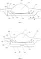
FIG. 1 is a side view of a lens according to Embodiment 1 of the present application; -
FIG. 2 is a diagram of positional relationship between the lens and a light-emitting assembly according to Embodiment 1 of the present application; -
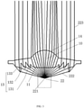
FIG. 3 is an optical path diagram of the lens according to Embodiment 1 of the present application; -
FIG. 4 is an assembly diagram of a light distribution assembly and the light-emitting assembly according to Embodiment 1 of the present application; -
FIG. 5 is a schematic diagram of a part of the structure of the lens according to Embodiment 1 of the present application; -
FIG. 6 is an internal schematic diagram of the lighting fixture according to Embodiment 2 of the present application; - Names and numerals of the components in the figures are listed below:
-
lens 10,light incident portion 11, mainlight incident surface 111, first auxiliarylight incident surface 112, second auxiliarylight incident surface 113, third auxiliarylight incident surface 114,reflective surface 13, firstreflective surface 131, secondreflective surface 132, thirdreflective surface 133, light-emittingportion 14, main light-emittingsurface 141, auxiliary light-emittingsurface 142,convex portion 16,first convex portion 161,second convex portion 162,third convex portion 163, light-emitting assembly 20,light plate 21,restrictive hole 211,lamp body 22, light-emittingcenter 221,incident light 222,emergent light 223,installation plate 30,connection hole 31,positioning groove 32,step shaft 33,lamp housing 40,lamp cavity 41, supportingportion 42,light outlet 43,transparent cover 50. - As shown in
FIG. 1 , the embodiment of the present application discloses alens 10, thelens 10 includes alight incident portion 11 and a light-emittingportion 14. As shown inFIG. 2 andFIG. 3 , thelight incident portion 11 is used to receiveincident light 222 emitted by thelamp body 22 of the light-emitting assembly 20, theincident light 222 enters thelight incident portion 11 and finally exits from the light-emittingportion 14 to formemergent light 223. The light-emittingportion 14 includes a main light-emittingsurface 141 and an auxiliary light-emittingsurface 142 surrounding the main light-emittingsurface 141, and the main light-emittingsurface 141 and the auxiliary light-emittingsurface 142 form a continuous light-emitting surface. Preferably, thelens 10 is a collimating lens, and theemergent light 223 is a collimated light. - The main light-emitting
surface 141 and the auxiliary light-emittingsurface 142 protrude toward a side away from thelight incident portion 11, the protruding height of the auxiliary light-emittingsurface 142 gradually decreases in a direction away from the main light-emittingsurface 141. The structure of the main light-emittingsurface 141 and the auxiliary light-emittingsurface 142 enables the light emitted from the light-emittingportion 14 to be more concentrated. The auxiliary light-emittingsurface 142 is a curved surface, which helps to further concentrate theemergent light 223. As shown inFIG. 4 , the auxiliary light-emittingsurface 142 has a ring structure, which enables theentire lens 10 to be more beautiful and also enables the light-emittingportion 14 to have larger area. - The
light incident portion 11 and the light-emittingportion 14 are arranged opposite to each other, and thelight incident portion 11 faces thelamp body 22 of the light-emitting assembly 20. Thelight incident portion 11 includes a mainlight incident surface 111, and the mainlight incident surface 111 protrudes toward a side away from the light-emittingportion 14. Thelight incident portion 11 includes the mainlight incident surface 111 and auxiliary light incident surfaces, and convexportions 16 are provided around the mainlight incident surface 111, theconvex portions 16 protrude toward the side away from the light-emittingportion 14, or theconvex portions 16 protrude toward thelamp body 22 of the light-emitting assembly 20, and surfaces of theconvex portions 16 facing the mainlight incident surface 111 are the auxiliary light incident surfaces, or surfaces of theconvex portions 16 facing thelamp body 22 are the auxiliary light incident surfaces, surfaces of theconvex portions 16 away from the mainlight incident surface 111 arereflective surfaces 13, or surfaces of theconvex portions 16 away from thelamp body 22 arereflective surfaces 13. Angles are formed between the auxiliary light incident surfaces and thereflective surfaces 13. As shown inFIG. 2 , both the auxiliary light incident surfaces and thereflective surfaces 13 are inclined surfaces, the thickness of theconvex portions 16 gradually decreases in a direction toward the light-emitting assembly 20, that is, the distance between the auxiliary light incident surfaces and thereflective surfaces 13 gradually decreases in the direction toward the light-emitting assembly 20. - As shown in
FIG. 3 , a part of theincident light 222 emitted by thelamp body 22 of the light-emitting assembly 20 enters thelens 10 from the mainlight incident surface 111, and another part of theincident light 222 enters thelens 10 from the auxiliary light incident surfaces. A part of the light entering the lens directly exits from the main light-emittingsurface 141 and the auxiliary light-emittingsurface 142, and another part of the light exits from the main light-emittingsurface 141 and the auxiliary light-emittingsurfaces 142 after being totally reflected by thereflective surfaces 13. - At least two
convex portions 16 are provided, and the protruding heights of the at least twoconvex portions 16 increase sequentially in the direction away from the mainlight incident surface 111, so that the auxiliary light incident surfaces can more fully receive the light emitted bylamp body 22 of the light-emitting assembly 20, and the light distribution effect is improved. Theconvex portions 16 preferably have a ring structure. The height of theconvex portion 16 furthest from the mainlight incident surface 111 is higher than the height of the mainlight incident surface 111, which is beneficial for the auxiliary light incident surfaces to more fully receive the light emitted by thelamp body 22 of the light-emitting assembly 20. - As shown in
FIG. 2 , preferably, at least threeconvex portions 16 are provided, and the threeconvex portions 16 sequentially are thefirst convex portion 161, thesecond convex portion 162, and thethird convex portion 163 in a direction away from the mainlight incident surface 111. A surface of thefirst convex portion 161 facing thelamp body 22 is the first auxiliarylight incident surface 112, a surface of thesecond convex portion 162 facing thelamp body 22 is the second auxiliarylight incident surface 113, and a surface of thethird convex portion 163 facing thelamp body 22 is the third auxiliarylight incident surface 114. A surface of thefirst convex portion 161 away from thelamp body 22 is the firstreflective surface 131, a surface of thesecond convex portion 162 away from thelamp body 22 is the secondreflective surface 132, and a surface of thethird convex portion 163 away from thelamp body 22 is the third reflective surface. - Refer to
FIG. 1 and FIG. 2 , the protruding height of thethird convex portion 163 is the largest, the protruding height of thethird convex portion 163 is higher than the mainlight incident surface 111. Among the three convex portions, the outer end of thethird convex portion 163 is closest to thelight plate 21 of the light-emitting assembly 20, the outer end of thefirst convex portion 161 is farthest from thelight plate 21, the distance between the outer end of thesecond convex portion 162 and thelight plate 21 is between the distance between the outer end of thefirst convex portion 161 and thelight plate 21 and the distance between the outer end of thethird convex portion 163 and thelight plate 21. - As shown in
FIG. 6 , the embodiment discloses a lighting fixture, which may be a downlight, the downlight includes alamp housing 40, and thelamp housing 40 has alamp cavity 41, the downlight also includes a light-emitting assembly 20, a light distribution assembly, and a power source, and the light-emitting assembly 20, the light distribution assembly, and the power source (not shown in the figure) are all arranged in thelamp cavity 41. The light-emitting assembly 20 is electrically connected to the power source, and the power source is electrically connected to an external power source through a threading hole on thelamp housing 40. The power source may not be provided in thelamp cavity 41, in another embodiment, the power source is provided outside thelamp cavity 41. - As shown in
FIG. 4 , the light distribution assembly includes aninstallation plate 30 and thelens 10 of Embodiment 1 distributed on theinstallation plate 30. One, two, three, four, ormore lenses 10 may be provided, and thelenses 10 and theinstallation plate 30 can be integrally injection molded, the molding process is simple, and no assembly is required. As shown inFIG. 6 , theinstallation plate 30 includes a first surface facing the light-emitting assembly 20 and a second surface away from the light-emitting assembly 20. The mainlight incident surface 111 of thelens 10 and theconvex portion 16 of thelens 10 are exposed outside the first surface and face the light-emitting assembly 20. The light-emittingportion 14 of thelens 10 is exposed outside the second surface. - In the following, the lighting fixture of this embodiment will be described with an example in which three
lenses 10 are provided. The three lenses are circumferentially distributed on theinstallation plate 30. The light-emittingassembly 20 includes thelight plate 21 and thelamp bodies 22 distributed on thelight plate 21, and the light-emittingassembly 20 includes at least three groups oflamp bodies 22, each group oflamp bodies 22 is arranged opposite to alens 10. The amount of thelamp bodies 22 included in each group oflamp bodies 22 may be provided as required, and the amount of thelamp bodies 22 included in each group oflamp bodies 22 may be one, in this case, the light-emitting center of this onelamp body 22 is the light-emitting center of the light-emittingassembly 20. In the case that each group oflamp bodies 22 includes at least twolamp bodies 22, the light-emitting center of the group oflamp bodies 22 is the light-emitting center of the light-emittingassembly 20. - The
installation plate 30 is provided with astep shaft 33 on the surface facing thelight plate 21, and thestep shaft 33 may be integrally injection molded with theinstallation plate 30, the molding process is simple, and no assembly is required. Thestep shaft 33 includes at least three shaft sections, and the interface of adjacent shaft sections is a restrictive surface. At least two restrictive surfaces are provided on thestep shaft 33. Preferably, thestep shaft 33 includes four shaft segments to form three restrictive surfaces. In the following, the lighting fixture of this embodiment will be described with an example in which four shaft sections of thestep shaft 33 are provided. - The diameters of the four shaft sections become larger in sequence in the direction away from the
light plate 21, the areas of the three restrictive surfaces become larger in sequence. Correspondingly, at least one group ofrestrictive holes 211 is distributed on thelight plate 21, the amount of groups of therestrictive holes 211 is the same as the amount of thestep shafts 33, and three groups of therestrictive holes 211 and threestep shafts 33 may be provided. The connection lines of distribution points of the threestep shafts 33 form a triangle, so that theinstallation plate 30 is reliably supported on thelight plate 21. The amount ofrestrictive holes 211 in each group is the same as that of restrictive surfaces, both of them are three. - Different step shafts are fitted with different restrictive holes in a plug-in manner, and different restrictive surfaces are restrictively fitted with different restrictive holes. The distance between the
installation plate 30 of the lighting fixture and thelight plate 21 of the lighting fixture in this embodiment is adjustable, so that the purpose of adjusting the beam angle can be achieved. The beam angle may be 12°, 24°, and 36°. The user can adjust the distance between theinstallation plate 30 and thelight plate 21 as needed, and then the beam angle can be adjusted. - The
installation plate 30 and thelight plate 21 are arranged in parallel, and the beam angles of thelenses 10 can be changed by changing the distance between theinstallation plate 30 and thelight plate 21. The distance between theinstallation plate 30 and thelight plate 21 is set according to the size of the light-emitting surface of thelamp body 22. Specifically, the length of the shaft sections of thestep shaft 33 are set according to the size of the light-emitting surface of thelamp body 22, so that after different restrictive surfaces are fitted with differentrestrictive holes 211, the beam angle can be 12°, 24°, and 36° . - In the process of adjusting the beam angle, firstly, the
installation plate 30 is separated from thelight plate 21, and then theinstallation plate 30 is rotated relative to thelight plate 21, and finally thestep shaft 33 is fitted with anotherrestrictive hole 211 in the plug-in manner, the anotherrestrictive hole 211 is restrictively fitted with another restrictive surface. Theinstallation plate 30 is preferably a disc-shaped structure, correspondingly, thelight plate 21 is also a disc-shaped structure. The center line of theinstallation plate 30 coincides with the center line of thelight plate 21, the advantage is that: during the rotation of theinstallation plate 30, theinstallation plate 30 and thelight plate 21 are always aligned in the length direction of thelamp housing 40, and the size in a horizontal direction will not be increased due to the relative rotation of theinstallation plate 30 and thelight plate 21, so there is no need to increase the horizontal size of thelamp cavity 41, which is beneficial to save the volume of thelamp cavity 41. The horizontal direction here refers to the direction perpendicular to the center line of theinstallation plate 30 or the center line of thelight plate 21. - The structure of the light-emitting
portion 14 of the lighting fixture of this embodiment enables theemergent light 223 to be more concentrated, and the beam angle according to this embodiment is adjustable. - As shown in
FIG. 4 , theinstallation plate 30 is provided with connection holes 31, correspondingly, threaded holes are provided on thelight plate 21, and theinstallation plate 30 and thelight plate 21 are detachably connected together by screws. Theinstallation plate 30 is provided withpositioning grooves 32, and thepositioning grooves 32 are provided on the edge of theinstallation plate 30, thepositioning grooves 32 are fitted with positioning blocks on the inner surface of thelamp housing 40 in a plug-in manner, so that theinstallation plate 30 and thelight plate 21 are positioned in thelamp cavity 41, and cannot be rotated. - The inner surface of the
lamp housing 40 is provided with a supportingportion 42 for supporting thelight plate 21 and fixing the positions of the light-emittingassembly 20 and the light distribution assembly in the length direction of thelamp housing 40. Thelamp housing 40 has alight outlet 43, the light-emittingportions 14 of thelenses 10 face thelight outlet 43, and thelight outlet 43 is equipped with atransparent cover 50 that blocks thelight outlet 43, and thetransparent cover 50 plays roles of dustproof and waterproof. - The light-emitting center of the
lamp body 22 is the light-emittingcenter 221. As shown inFIG. 5 , in order to improve the light output efficiency of thelens 10, an angle a is formed between the center line of thelens 10 and the line connecting the outer end of the mainlight incident surface 111 to the light-emittingcenter 221, and the angle a is 40°-50 °, for example, the angle a may be 46°. An angle b is formed between the center line of thelens 10 and the line connecting the outer end of the firstconvex portion 161 to the light-emittingcenter 221, and the angle b is 50°-60 °, for example, the angle b may be 54.9°. An angle c is formed between the center line of thelens 10 and the line connecting the outer end of the secondconvex portion 162 to the light-emittingcenter 221, and the angle c is 60°-70 °, for example, the angle c may be 62.3°. An angle d is formed between the center line of thelens 10 and the line connecting the outer end of the thirdconvex portion 163 to the light-emittingcenter 221, and the angle d is 70°-80 °, for example, the angle d may be 74.9°. - The above embodiments of the present application focus on the differences between the various embodiments, and as long as the different optimized features between the various embodiments are not contradictory, they can be combined to form a better embodiment. For succinct writing, they won't be repeated herein.
- The above embodiments are only examples of the present application, and do not impose any limitation on the present application. For those skilled in the art, the present application can have various modifications and changes. Any modification, equivalent replacement, improvement, etc. made within the spirit and principle of the present application shall be included in the scope of the claims of the present application.
Claims (12)
- A lens (10), wherein, comprising a light incident portion (11) and a light-emitting portion (14), the light-emitting portion (14) comprises a main light-emitting surface (141) and an auxiliary light-emitting surface (142) surrounding the main light-emitting surface (141); the main light-emitting surface (141) and the auxiliary light-emitting surface (142) protrude toward a side away from the light incident portion (11), the auxiliary light-emitting surface (142) is a curved surface; and the auxiliary light-emitting surface (142) has a protruding height gradually decreasing in a direction away from the main light-emitting surface (141).
- The lens (10) according to claim 1, wherein the lens (10) is a collimating lens.
- The lens (10) according to claim 1, wherein the light incident portion (11) comprises a main light incident surface (11), and the main light incident surface (11) protrudes toward a side away from the light-emitting portion (14).
- The lens (10) according to claim 1, wherein the light incident portion (11) comprises a main light incident surface (11) and an auxiliary light incident surface, and a convex portion (16) is provided around the main light incident surface (11), the convex portion (16) protrudes toward the side away from the light-emitting portion (14), and a surface of the convex portion (16) facing the main light incident surface (11) forms the auxiliary light incident surface, and a surface of the convex portion (16) away from the main light incident surface (11) forms a reflective surface (13), and the reflective surface (13) is a total reflective surface.
- The lens (10) according to claim 4, wherein at least two convex portions (16) are provided, and the at least two convex portions (16) have heights increasing sequentially in a direction away from the main light incident surface (11).
- A lighting fixture, wherein, comprising a lamp housing (40), a light-emitting assembly (20) and a light distribution assembly, the light distribution assembly comprises a lens (10) according to any one of claims 1 to 3, the lamp housing (40) has a lamp cavity (41), and the light-emitting assembly (20) and the light distribution assembly are arranged in the lamp cavity (41).
- The lighting fixture according to claim 6, wherein the light distribution assembly further comprises a installation plate (30), the lens (10) is arranged on the installation plate (30), and the installation plate (30) is provided with a step shaft (33); the step shaft (33) has at least three shaft sections, and an interface of every two adjacent shaft sections among the three shaft sections forms a restrictive surface; the light-emitting assembly comprises a light plate (21), the light plate (21) is provided with at least two restrictive holes (211) with different apertures, the step shaft (33) is fitted with the restrictive holes (211) in a plug-in manner, and the restrictive holes (211) are restrictively fitted with the restrictive surfaces.
- The lighting fixture according to claim 7, wherein the installation plate (30) and the light plate (21) are both disc-shaped structures, and a center line of the installation plate (30) coincides with a center line of the light plate (21).
- The lighting fixture according to claim 7, wherein different restrictive holes (211) are fitted with different restrictive surfaces so that the lens (10) forms different beam angles, and the beam angles comprise at least any two of 12°, 24°, and 36°.
- The lighting fixture according to claim 6, wherein the light incident portion (11) comprises a main light incident surface (11) and auxiliary light incident surfaces, and at least two convex portions (16) are provided around the main light incident surface (11), the convex portions (16) protrude toward the side away from the light-emitting portion (14), and surfaces of the convex portions (16) facing the main light incident surface (11) form the auxiliary light incident surfaces, and surfaces of the convex portions (16) away from the main light incident surface (11) form reflective surfaces (13), angles between a center line of the lens (10) and connection lines connecting outer ends of the at least two convex portions (16) to a light-emitting center of the light-emitting assembly (20) increases sequentially in the direction away from the main light incident surface (11).
- The lighting fixture according to claim 10, wherein the at least two of the convex portions (16) comprise a first convex portion (161), a second convex portion (162), and a third convex portion (163) that are sequentially arranged from proximal position to distal position with respect to the main light incident surface (11), an angle between the center line of the lens (10) and a connection line connecting an outer end of the first convex portion (161) to the light-emitting center of the light-emitting assembly (20), an angle between the center line of the lens (10) and a connection line connecting an outer end of the second convex portion (162) to the light-emitting center of the light-emitting assembly (20), and an angle between the center line of the lens (10) and a connection line connecting an outer end of the third convex portion (163) to the light-emitting center of the light-emitting assembly (20) are respectively 50°-60°, 60°-70°, and 70°-80° .
- The lighting fixture according to claim 10 or 11, wherein an angle between the center line of the lens (10) and a connection line connecting an outer end of the main light incident surface (11) to the light-emitting center of the light-emitting assembly (20) is 40°-50°.
Applications Claiming Priority (2)
| Application Number | Priority Date | Filing Date | Title |
|---|---|---|---|
| CN201920922164.8U CN209782513U (en) | 2019-06-19 | 2019-06-19 | Lens and lamp |
| PCT/CN2020/094078 WO2020253526A1 (en) | 2019-06-19 | 2020-06-03 | Lens and lamp |
Publications (3)
| Publication Number | Publication Date |
|---|---|
| EP3940290A1 true EP3940290A1 (en) | 2022-01-19 |
| EP3940290A4 EP3940290A4 (en) | 2022-04-06 |
| EP3940290B1 EP3940290B1 (en) | 2025-04-02 |
Family
ID=68789540
Family Applications (1)
| Application Number | Title | Priority Date | Filing Date |
|---|---|---|---|
| EP20827438.1A Active EP3940290B1 (en) | 2019-06-19 | 2020-06-03 | Lens and lamp |
Country Status (4)
| Country | Link |
|---|---|
| US (1) | US11774062B2 (en) |
| EP (1) | EP3940290B1 (en) |
| CN (1) | CN209782513U (en) |
| WO (1) | WO2020253526A1 (en) |
Families Citing this family (4)
| Publication number | Priority date | Publication date | Assignee | Title |
|---|---|---|---|---|
| CN209782513U (en) | 2019-06-19 | 2019-12-13 | 苏州欧普照明有限公司 | Lens and lamp |
| CN112503427A (en) * | 2020-10-29 | 2021-03-16 | 惠阳帝宇工业有限公司 | Lamp and emergency lamp |
| EP4599296A1 (en) * | 2022-10-03 | 2025-08-13 | Lumileds LLC | Illuminator comprising biconvex lens with tir teeth |
| CN220707163U (en) * | 2023-08-28 | 2024-04-02 | 深圳市万家照明有限公司 | LED lamp with lens module capable of independently and stepwise adjusting light emitting angle |
Family Cites Families (19)
| Publication number | Priority date | Publication date | Assignee | Title |
|---|---|---|---|---|
| JPH05281402A (en) * | 1992-03-31 | 1993-10-29 | Sunx Ltd | Optical device |
| DE19834521A1 (en) * | 1998-07-31 | 2000-02-03 | Aqua Signal Ag | Process for the production of a flat lens on a catadioptric basis, and flat lens produced by this process |
| JP4293857B2 (en) * | 2003-07-29 | 2009-07-08 | シチズン電子株式会社 | Lighting device using Fresnel lens |
| JP3686660B2 (en) * | 2003-09-16 | 2005-08-24 | シーシーエス株式会社 | Light irradiation device and optical unit |
| JP4376289B2 (en) * | 2005-06-01 | 2009-12-02 | シーシーエス株式会社 | Light irradiation device |
| JP5311779B2 (en) * | 2007-08-21 | 2013-10-09 | シチズン電子株式会社 | LED light emitting device |
| JP4879218B2 (en) * | 2008-04-25 | 2012-02-22 | シャープ株式会社 | Lens body, light source unit, and illumination device |
| CN201436456U (en) * | 2009-07-03 | 2010-04-07 | 广州市佛达信号设备有限公司 | LED automobile rear combined signal lamp |
| US8358081B2 (en) * | 2009-08-21 | 2013-01-22 | Teledyne Technologies Incorporated | Lamp assembly |
| US20130249375A1 (en) * | 2012-03-21 | 2013-09-26 | George W. Panagotacos | Anti-icing solid state aircraft lamp assembly with defroster apparatus, system, and method |
| WO2014020475A1 (en) * | 2012-07-30 | 2014-02-06 | Koninklijke Philips N.V. | Fresnel type lens for lighting applications |
| US9829689B2 (en) * | 2013-05-14 | 2017-11-28 | Ledil Oy | Light guide for modifying a light distribution pattern |
| EP3278012B1 (en) * | 2015-04-02 | 2020-12-23 | Signify Holding B.V. | Optical beam shaping device and spot light using the same |
| JP2017067831A (en) * | 2015-09-28 | 2017-04-06 | 三菱電機株式会社 | Lens and light-emitting device |
| CN105276524B (en) * | 2015-11-23 | 2019-04-16 | 惠州市西顿工业发展有限公司 | A kind of varifocal optical lens |
| EP3593179B1 (en) * | 2017-03-07 | 2021-01-27 | Signify Holding B.V. | A collimator and a lighting unit |
| CN108131573A (en) * | 2018-02-05 | 2018-06-08 | 深圳华唐锐照明电器有限公司 | A kind of waterproof LED lamp at adjustment beam angle |
| CN209445299U (en) * | 2019-03-19 | 2019-09-27 | 欧普照明股份有限公司 | Lens, light source module group and lamps and lanterns |
| CN209782513U (en) * | 2019-06-19 | 2019-12-13 | 苏州欧普照明有限公司 | Lens and lamp |
-
2019
- 2019-06-19 CN CN201920922164.8U patent/CN209782513U/en active Active
-
2020
- 2020-06-03 EP EP20827438.1A patent/EP3940290B1/en active Active
- 2020-06-03 WO PCT/CN2020/094078 patent/WO2020253526A1/en not_active Ceased
-
2021
- 2021-12-20 US US17/556,059 patent/US11774062B2/en active Active
Also Published As
| Publication number | Publication date |
|---|---|
| US11774062B2 (en) | 2023-10-03 |
| EP3940290A4 (en) | 2022-04-06 |
| CN209782513U (en) | 2019-12-13 |
| US20220113004A1 (en) | 2022-04-14 |
| WO2020253526A1 (en) | 2020-12-24 |
| EP3940290B1 (en) | 2025-04-02 |
Similar Documents
| Publication | Publication Date | Title |
|---|---|---|
| US11774062B2 (en) | Lens with total reflective incident surface and lighting fixture | |
| US8348475B2 (en) | Lens with controlled backlight management | |
| US11655959B2 (en) | Optical structures for light emitting diodes (LEDs) | |
| EP3027963B1 (en) | Reflector for directed beam led illumination | |
| US10190736B1 (en) | Apparatus for providing off-axis illumination | |
| EP4092460A1 (en) | Lens housing, lens module and light source system | |
| US10564435B2 (en) | Optical lens, light guide member and double sided luminosity device | |
| CN108375043B (en) | Beam shaping devices, optical assemblies and lighting and/or signaling devices | |
| CN207975488U (en) | The optical module of adjustable spot and the LED component of adjustable spot | |
| CN221261288U (en) | Optical lens module and lamp | |
| CN117080858A (en) | Circumferential array integrated semiconductor laser | |
| WO2019085244A1 (en) | Laser street lamp | |
| CN119860512B (en) | Lamp set | |
| CN221684351U (en) | Optical off-axis line lens and lamp | |
| WO2021063146A1 (en) | Light distribution assembly and illuminating lamp | |
| CN223663186U (en) | Light guide system, car lamp and vehicle | |
| CN212986801U (en) | Lighting device and lamp | |
| CN222703146U (en) | Desk lamp reflector | |
| US20260132909A1 (en) | Aspheric lens | |
| CN215523166U (en) | Optical lens, semiconductor light emitting device and light source module | |
| CN217875686U (en) | Reflection cup and lighting lamp | |
| CN212901335U (en) | Optical light distribution module of laser reflection cup | |
| CN111006185B (en) | Lens and lamp | |
| CN103851537A (en) | LED lamp and lens thereof | |
| WO2026040014A1 (en) | Light guide plate, signal lamp and vehicle |
Legal Events
| Date | Code | Title | Description |
|---|---|---|---|
| STAA | Information on the status of an ep patent application or granted ep patent |
Free format text: STATUS: THE INTERNATIONAL PUBLICATION HAS BEEN MADE |
|
| PUAI | Public reference made under article 153(3) epc to a published international application that has entered the european phase |
Free format text: ORIGINAL CODE: 0009012 |
|
| STAA | Information on the status of an ep patent application or granted ep patent |
Free format text: STATUS: REQUEST FOR EXAMINATION WAS MADE |
|
| 17P | Request for examination filed |
Effective date: 20211012 |
|
| AK | Designated contracting states |
Kind code of ref document: A1 Designated state(s): AL AT BE BG CH CY CZ DE DK EE ES FI FR GB GR HR HU IE IS IT LI LT LU LV MC MK MT NL NO PL PT RO RS SE SI SK SM TR |
|
| A4 | Supplementary search report drawn up and despatched |
Effective date: 20220310 |
|
| RIC1 | Information provided on ipc code assigned before grant |
Ipc: F21V 17/02 20060101ALN20220303BHEP Ipc: F21V 17/00 20060101ALN20220303BHEP Ipc: F21V 5/00 20180101ALI20220303BHEP Ipc: G02B 19/00 20060101ALI20220303BHEP Ipc: F21V 7/00 20060101ALI20220303BHEP Ipc: F21Y 115/10 20160101ALI20220303BHEP Ipc: F21V 14/06 20060101ALI20220303BHEP Ipc: F21V 17/10 20060101ALI20220303BHEP Ipc: F21V 5/04 20060101AFI20220303BHEP |
|
| DAV | Request for validation of the european patent (deleted) | ||
| DAX | Request for extension of the european patent (deleted) | ||
| STAA | Information on the status of an ep patent application or granted ep patent |
Free format text: STATUS: EXAMINATION IS IN PROGRESS |
|
| 17Q | First examination report despatched |
Effective date: 20221020 |
|
| GRAP | Despatch of communication of intention to grant a patent |
Free format text: ORIGINAL CODE: EPIDOSNIGR1 |
|
| STAA | Information on the status of an ep patent application or granted ep patent |
Free format text: STATUS: GRANT OF PATENT IS INTENDED |
|
| RIC1 | Information provided on ipc code assigned before grant |
Ipc: F21V 17/02 20060101ALN20241219BHEP Ipc: F21V 17/00 20060101ALN20241219BHEP Ipc: F21V 5/00 20180101ALI20241219BHEP Ipc: G02B 19/00 20060101ALI20241219BHEP Ipc: F21V 7/00 20060101ALI20241219BHEP Ipc: F21Y 115/10 20160101ALI20241219BHEP Ipc: F21V 14/06 20060101ALI20241219BHEP Ipc: F21V 17/10 20060101ALI20241219BHEP Ipc: F21V 5/04 20060101AFI20241219BHEP |
|
| INTG | Intention to grant announced |
Effective date: 20250109 |
|
| GRAS | Grant fee paid |
Free format text: ORIGINAL CODE: EPIDOSNIGR3 |
|
| GRAA | (expected) grant |
Free format text: ORIGINAL CODE: 0009210 |
|
| STAA | Information on the status of an ep patent application or granted ep patent |
Free format text: STATUS: THE PATENT HAS BEEN GRANTED |
|
| AK | Designated contracting states |
Kind code of ref document: B1 Designated state(s): AL AT BE BG CH CY CZ DE DK EE ES FI FR GB GR HR HU IE IS IT LI LT LU LV MC MK MT NL NO PL PT RO RS SE SI SK SM TR |
|
| REG | Reference to a national code |
Ref country code: GB Ref legal event code: FG4D |
|
| REG | Reference to a national code |
Ref country code: CH Ref legal event code: EP |
|
| REG | Reference to a national code |
Ref country code: IE Ref legal event code: FG4D |
|
| REG | Reference to a national code |
Ref country code: DE Ref legal event code: R096 Ref document number: 602020048840 Country of ref document: DE |
|
| REG | Reference to a national code |
Ref country code: NL Ref legal event code: FP |
|
| PGFP | Annual fee paid to national office [announced via postgrant information from national office to epo] |
Ref country code: NL Payment date: 20250528 Year of fee payment: 6 |
|
| PGFP | Annual fee paid to national office [announced via postgrant information from national office to epo] |
Ref country code: DE Payment date: 20250617 Year of fee payment: 6 |
|
| PGFP | Annual fee paid to national office [announced via postgrant information from national office to epo] |
Ref country code: GB Payment date: 20250625 Year of fee payment: 6 |
|
| PGFP | Annual fee paid to national office [announced via postgrant information from national office to epo] |
Ref country code: BE Payment date: 20250625 Year of fee payment: 6 |
|
| PGFP | Annual fee paid to national office [announced via postgrant information from national office to epo] |
Ref country code: FR Payment date: 20250630 Year of fee payment: 6 |
|
| REG | Reference to a national code |
Ref country code: AT Ref legal event code: MK05 Ref document number: 1781580 Country of ref document: AT Kind code of ref document: T Effective date: 20250402 |
|
| PG25 | Lapsed in a contracting state [announced via postgrant information from national office to epo] |
Ref country code: PT Free format text: LAPSE BECAUSE OF FAILURE TO SUBMIT A TRANSLATION OF THE DESCRIPTION OR TO PAY THE FEE WITHIN THE PRESCRIBED TIME-LIMIT Effective date: 20250804 Ref country code: FI Free format text: LAPSE BECAUSE OF FAILURE TO SUBMIT A TRANSLATION OF THE DESCRIPTION OR TO PAY THE FEE WITHIN THE PRESCRIBED TIME-LIMIT Effective date: 20250402 Ref country code: ES Free format text: LAPSE BECAUSE OF FAILURE TO SUBMIT A TRANSLATION OF THE DESCRIPTION OR TO PAY THE FEE WITHIN THE PRESCRIBED TIME-LIMIT Effective date: 20250402 |
|
| REG | Reference to a national code |
Ref country code: LT Ref legal event code: MG9D |
|
| PG25 | Lapsed in a contracting state [announced via postgrant information from national office to epo] |
Ref country code: NO Free format text: LAPSE BECAUSE OF FAILURE TO SUBMIT A TRANSLATION OF THE DESCRIPTION OR TO PAY THE FEE WITHIN THE PRESCRIBED TIME-LIMIT Effective date: 20250702 Ref country code: GR Free format text: LAPSE BECAUSE OF FAILURE TO SUBMIT A TRANSLATION OF THE DESCRIPTION OR TO PAY THE FEE WITHIN THE PRESCRIBED TIME-LIMIT Effective date: 20250703 |
|
| PG25 | Lapsed in a contracting state [announced via postgrant information from national office to epo] |
Ref country code: PL Free format text: LAPSE BECAUSE OF FAILURE TO SUBMIT A TRANSLATION OF THE DESCRIPTION OR TO PAY THE FEE WITHIN THE PRESCRIBED TIME-LIMIT Effective date: 20250402 |
|
| PG25 | Lapsed in a contracting state [announced via postgrant information from national office to epo] |
Ref country code: BG Free format text: LAPSE BECAUSE OF FAILURE TO SUBMIT A TRANSLATION OF THE DESCRIPTION OR TO PAY THE FEE WITHIN THE PRESCRIBED TIME-LIMIT Effective date: 20250402 |
|
| PG25 | Lapsed in a contracting state [announced via postgrant information from national office to epo] |
Ref country code: HR Free format text: LAPSE BECAUSE OF FAILURE TO SUBMIT A TRANSLATION OF THE DESCRIPTION OR TO PAY THE FEE WITHIN THE PRESCRIBED TIME-LIMIT Effective date: 20250402 |
|
| PG25 | Lapsed in a contracting state [announced via postgrant information from national office to epo] |
Ref country code: AT Free format text: LAPSE BECAUSE OF FAILURE TO SUBMIT A TRANSLATION OF THE DESCRIPTION OR TO PAY THE FEE WITHIN THE PRESCRIBED TIME-LIMIT Effective date: 20250402 |
|
| PG25 | Lapsed in a contracting state [announced via postgrant information from national office to epo] |
Ref country code: RS Free format text: LAPSE BECAUSE OF FAILURE TO SUBMIT A TRANSLATION OF THE DESCRIPTION OR TO PAY THE FEE WITHIN THE PRESCRIBED TIME-LIMIT Effective date: 20250702 |
|
| PG25 | Lapsed in a contracting state [announced via postgrant information from national office to epo] |
Ref country code: IS Free format text: LAPSE BECAUSE OF FAILURE TO SUBMIT A TRANSLATION OF THE DESCRIPTION OR TO PAY THE FEE WITHIN THE PRESCRIBED TIME-LIMIT Effective date: 20250802 |
|
| PG25 | Lapsed in a contracting state [announced via postgrant information from national office to epo] |
Ref country code: LV Free format text: LAPSE BECAUSE OF FAILURE TO SUBMIT A TRANSLATION OF THE DESCRIPTION OR TO PAY THE FEE WITHIN THE PRESCRIBED TIME-LIMIT Effective date: 20250402 |
|
| REG | Reference to a national code |
Ref country code: DE Ref legal event code: R097 Ref document number: 602020048840 Country of ref document: DE |
|
| PG25 | Lapsed in a contracting state [announced via postgrant information from national office to epo] |
Ref country code: DK Free format text: LAPSE BECAUSE OF FAILURE TO SUBMIT A TRANSLATION OF THE DESCRIPTION OR TO PAY THE FEE WITHIN THE PRESCRIBED TIME-LIMIT Effective date: 20250402 Ref country code: SM Free format text: LAPSE BECAUSE OF FAILURE TO SUBMIT A TRANSLATION OF THE DESCRIPTION OR TO PAY THE FEE WITHIN THE PRESCRIBED TIME-LIMIT Effective date: 20250402 |
|
| PG25 | Lapsed in a contracting state [announced via postgrant information from national office to epo] |
Ref country code: CZ Free format text: LAPSE BECAUSE OF FAILURE TO SUBMIT A TRANSLATION OF THE DESCRIPTION OR TO PAY THE FEE WITHIN THE PRESCRIBED TIME-LIMIT Effective date: 20250402 |
|
| PG25 | Lapsed in a contracting state [announced via postgrant information from national office to epo] |
Ref country code: EE Free format text: LAPSE BECAUSE OF FAILURE TO SUBMIT A TRANSLATION OF THE DESCRIPTION OR TO PAY THE FEE WITHIN THE PRESCRIBED TIME-LIMIT Effective date: 20250402 |
|
| PG25 | Lapsed in a contracting state [announced via postgrant information from national office to epo] |
Ref country code: RO Free format text: LAPSE BECAUSE OF FAILURE TO SUBMIT A TRANSLATION OF THE DESCRIPTION OR TO PAY THE FEE WITHIN THE PRESCRIBED TIME-LIMIT Effective date: 20250402 Ref country code: SK Free format text: LAPSE BECAUSE OF FAILURE TO SUBMIT A TRANSLATION OF THE DESCRIPTION OR TO PAY THE FEE WITHIN THE PRESCRIBED TIME-LIMIT Effective date: 20250402 |
|
| REG | Reference to a national code |
Ref country code: CH Ref legal event code: H13 Free format text: ST27 STATUS EVENT CODE: U-0-0-H10-H13 (AS PROVIDED BY THE NATIONAL OFFICE) Effective date: 20260127 |
|
| PG25 | Lapsed in a contracting state [announced via postgrant information from national office to epo] |
Ref country code: IT Free format text: LAPSE BECAUSE OF FAILURE TO SUBMIT A TRANSLATION OF THE DESCRIPTION OR TO PAY THE FEE WITHIN THE PRESCRIBED TIME-LIMIT Effective date: 20250402 |
|
| PG25 | Lapsed in a contracting state [announced via postgrant information from national office to epo] |
Ref country code: MC Free format text: LAPSE BECAUSE OF FAILURE TO SUBMIT A TRANSLATION OF THE DESCRIPTION OR TO PAY THE FEE WITHIN THE PRESCRIBED TIME-LIMIT Effective date: 20250402 |
|
| PLBE | No opposition filed within time limit |
Free format text: ORIGINAL CODE: 0009261 |
|
| STAA | Information on the status of an ep patent application or granted ep patent |
Free format text: STATUS: NO OPPOSITION FILED WITHIN TIME LIMIT |
|
| REG | Reference to a national code |
Ref country code: CH Ref legal event code: L10 Free format text: ST27 STATUS EVENT CODE: U-0-0-L10-L00 (AS PROVIDED BY THE NATIONAL OFFICE) Effective date: 20260211 |
|
| PG25 | Lapsed in a contracting state [announced via postgrant information from national office to epo] |
Ref country code: LU Free format text: LAPSE BECAUSE OF NON-PAYMENT OF DUE FEES Effective date: 20250603 |
|
| 26N | No opposition filed |
Effective date: 20260105 |
|
| PG25 | Lapsed in a contracting state [announced via postgrant information from national office to epo] |
Ref country code: IE Free format text: LAPSE BECAUSE OF NON-PAYMENT OF DUE FEES Effective date: 20250603 |
|
| PG25 | Lapsed in a contracting state [announced via postgrant information from national office to epo] |
Ref country code: CH Free format text: LAPSE BECAUSE OF NON-PAYMENT OF DUE FEES Effective date: 20250630 |