EP3940233A1 - Scroll compressor and refrigeration device provided with same - Google Patents
Scroll compressor and refrigeration device provided with same Download PDFInfo
- Publication number
- EP3940233A1 EP3940233A1 EP20810215.2A EP20810215A EP3940233A1 EP 3940233 A1 EP3940233 A1 EP 3940233A1 EP 20810215 A EP20810215 A EP 20810215A EP 3940233 A1 EP3940233 A1 EP 3940233A1
- Authority
- EP
- European Patent Office
- Prior art keywords
- casing
- scroll
- fixed scroll
- housing
- face
- Prior art date
- Legal status (The legal status is an assumption and is not a legal conclusion. Google has not performed a legal analysis and makes no representation as to the accuracy of the status listed.)
- Granted
Links
Images



Classifications
-
- F—MECHANICAL ENGINEERING; LIGHTING; HEATING; WEAPONS; BLASTING
- F04—POSITIVE - DISPLACEMENT MACHINES FOR LIQUIDS; PUMPS FOR LIQUIDS OR ELASTIC FLUIDS
- F04C—ROTARY-PISTON, OR OSCILLATING-PISTON, POSITIVE-DISPLACEMENT MACHINES FOR LIQUIDS; ROTARY-PISTON, OR OSCILLATING-PISTON, POSITIVE-DISPLACEMENT PUMPS
- F04C18/00—Rotary-piston pumps specially adapted for elastic fluids
- F04C18/02—Rotary-piston pumps specially adapted for elastic fluids of arcuate-engagement type, i.e. with circular translatory movement of co-operating members, each member having the same number of teeth or tooth-equivalents
- F04C18/0207—Rotary-piston pumps specially adapted for elastic fluids of arcuate-engagement type, i.e. with circular translatory movement of co-operating members, each member having the same number of teeth or tooth-equivalents both members having co-operating elements in spiral form
- F04C18/0215—Rotary-piston pumps specially adapted for elastic fluids of arcuate-engagement type, i.e. with circular translatory movement of co-operating members, each member having the same number of teeth or tooth-equivalents both members having co-operating elements in spiral form where only one member is moving
-
- F—MECHANICAL ENGINEERING; LIGHTING; HEATING; WEAPONS; BLASTING
- F04—POSITIVE - DISPLACEMENT MACHINES FOR LIQUIDS; PUMPS FOR LIQUIDS OR ELASTIC FLUIDS
- F04C—ROTARY-PISTON, OR OSCILLATING-PISTON, POSITIVE-DISPLACEMENT MACHINES FOR LIQUIDS; ROTARY-PISTON, OR OSCILLATING-PISTON, POSITIVE-DISPLACEMENT PUMPS
- F04C2230/00—Manufacture
- F04C2230/20—Manufacture essentially without removing material
- F04C2230/23—Manufacture essentially without removing material by permanently joining parts together
- F04C2230/231—Manufacture essentially without removing material by permanently joining parts together by welding
-
- F—MECHANICAL ENGINEERING; LIGHTING; HEATING; WEAPONS; BLASTING
- F04—POSITIVE - DISPLACEMENT MACHINES FOR LIQUIDS; PUMPS FOR LIQUIDS OR ELASTIC FLUIDS
- F04C—ROTARY-PISTON, OR OSCILLATING-PISTON, POSITIVE-DISPLACEMENT MACHINES FOR LIQUIDS; ROTARY-PISTON, OR OSCILLATING-PISTON, POSITIVE-DISPLACEMENT PUMPS
- F04C2230/00—Manufacture
- F04C2230/60—Assembly methods
- F04C2230/602—Gap; Clearance
-
- F—MECHANICAL ENGINEERING; LIGHTING; HEATING; WEAPONS; BLASTING
- F04—POSITIVE - DISPLACEMENT MACHINES FOR LIQUIDS; PUMPS FOR LIQUIDS OR ELASTIC FLUIDS
- F04C—ROTARY-PISTON, OR OSCILLATING-PISTON, POSITIVE-DISPLACEMENT MACHINES FOR LIQUIDS; ROTARY-PISTON, OR OSCILLATING-PISTON, POSITIVE-DISPLACEMENT PUMPS
- F04C2240/00—Components
- F04C2240/30—Casings or housings
-
- F—MECHANICAL ENGINEERING; LIGHTING; HEATING; WEAPONS; BLASTING
- F04—POSITIVE - DISPLACEMENT MACHINES FOR LIQUIDS; PUMPS FOR LIQUIDS OR ELASTIC FLUIDS
- F04C—ROTARY-PISTON, OR OSCILLATING-PISTON, POSITIVE-DISPLACEMENT MACHINES FOR LIQUIDS; ROTARY-PISTON, OR OSCILLATING-PISTON, POSITIVE-DISPLACEMENT PUMPS
- F04C2240/00—Components
- F04C2240/60—Shafts
Definitions
- the present disclosure relates to a scroll compressor and a refrigeration apparatus including the same.
- Scroll compressors including a casing and a compression mechanism having a fixed scroll and a housing have been known (e.g., Patent Document 1).
- a housing of a scroll compressor of this document has a pressing portion that is pressed against a casing, and a supporting portion connected to the pressing portion and extending axially.
- An end face of the supporting portion near a fixed scroll is a fastening face to which the fixed scroll is fastened.
- Patent Document 1 Japanese Unexamined Patent Publication No. 2017-25762
- the position of the supporting portion connected to the pressing portion may vary between before and after fixing of the housing to the casing. A large amount of variation in this position reduces the sealing performance between the fixed scroll and the fastening face of the supporting portion and reduces the efficiency of the scroll compressor.
- a first aspect of the present disclosure is directed to a scroll compressor (1).
- the scroll compressor (1) includes: a casing (10) having a cylindrical shape; a compression mechanism (20) housed in the casing (10) and including a fixed scroll (30), a movable scroll (40), and a housing (21); and a drive shaft (60) configured to rotate the movable scroll (40), wherein the housing (21) includes: a bearing portion (22) configured to rotatably support the drive shaft (60); a body portion (23) continuous with the bearing portion (22) and extending radially outward; a pressing portion (24) provided radially outside the body portion (23) to press the casing (10); and a supporting portion (25) extending from a face of the body portion (23) near the fixed scroll (30) in an axial direction toward the fixed scroll (30), an end face of the supporting portion (25) near the fixed scroll (30) is a fastening face (25a) to which the fixed scroll (30) is fastened, a gap (G1) is formed between an inner peripheral surface of the cas
- the radial pressure applied from the casing (10) to the pressing portion (24) is securely received by the body portion (23) extending radially.
- This configuration reduces the variation in the position of the supporting portion (25), and enhances the sealing performance between the fastening face (25a) and the fixed scroll (30). It is therefore possible to improve the efficiency of the scroll compressor (1).
- a second aspect of the present disclosure is an embodiment of the first aspect.
- the axial length (L1) of the gap (G1) is greater than the axial length (L2) of the inner peripheral surface of the supporting portion (25).
- This configuration of the second aspect further reduces the variation in the position of the supporting portion (25), and further enhances the sealing performance between the fastening face (25a) and the fixed scroll (30). It is therefore possible to further improve the efficiency of the scroll compressor (1).
- a third aspect of the present disclosure is an embodiment of the first or second aspect.
- the housing (21) has a weld portion (26) welded to the casing (10), and at least part of the pressing portion (24) and at least part of the weld portion (26) are arranged side by side in a circumferential direction of the casing (10).
- this configuration of the third aspect can downsize the housing (21) in the axial direction, and in turn, can downsize the scroll compressor (1).
- a fourth aspect of the present disclosure is an embodiment of the third aspect.
- the weld portion (26) communicates with an internal space of the casing (10) through the gap (G1).
- This configuration of the fourth aspect allows welding gas to be released into the internal space of the casing (10) through the gap (G1) when the housing (21) is welded to the casing (10), thereby reducing poor welding.
- a fifth aspect of the present disclosure is directed to a refrigeration apparatus (100).
- the refrigeration apparatus (100) includes the scroll compressor (1) of any one of the first to fourth aspects.
- a scroll compressor (1) according to this embodiment is used for a refrigeration apparatus (100).
- the refrigeration apparatus (100) include an air conditioner that adjusts the temperature and humidity of air, a cooling apparatus that cools its internal space, and a hot water supply apparatus that produces hot water.
- the refrigeration apparatus (100) includes a refrigerant circuit (101) that performs a refrigeration cycle.
- the refrigerant circuit (101) includes the scroll compressor (1), a condenser (102), an expansion mechanism (103), and an evaporator (104).
- a refrigerant compressed by the scroll compressor (1) dissipates heat in the condenser (102) and is decompressed in the expansion mechanism (103).
- the decompressed refrigerant evaporates in the evaporator (104), and is sucked into the scroll compressor (1).
- the scroll compressor (1) includes a casing (10), a compression mechanism (20), an electric motor (50), and a drive shaft (60).
- the casing (10) is in the shape of a vertically long cylinder with both ends closed.
- the casing (10) houses therein the compression mechanism (20) and the electric motor (50) sequentially arranged from top.
- the drive shaft (60) extending in the casing (10) in an axial direction (vertical direction) connects the compression mechanism (20) and the electric motor (50).
- the casing (10) is provided with a suction pipe (11) and a discharge pipe (12).
- the suction pipe (11) passes through an upper portion of the casing (10) in the axial direction so as to be connected to the compression mechanism (20).
- the suction pipe (11) introduces a low-pressure fluid (for example, a gas refrigerant) into the compression mechanism (20).
- the discharge pipe (12) passes through the barrel of the casing (10) in a radial direction to communicate with the internal space of the casing (10).
- the discharge pipe (12) introduces a high-pressure fluid in the casing (10) out of the casing (10).
- the compression mechanism (20) is housed in the casing (10).
- the compression mechanism (20) is configured to compress the fluid introduced through the suction pipe (11) and discharge the compressed fluid into the casing (10).
- the configuration of the compression mechanism (20) will be described in detail.
- the electric motor (50) is housed in the casing (10), and is disposed below the compression mechanism (20).
- the electric motor (50) includes a stator (51) and a rotor (52).
- the stator (51) is substantially in the shape of a cylinder, and is fixed to the casing (10).
- the rotor (52) is inserted in the stator (51) to be rotatable on the inner periphery of the stator (51).
- the drive shaft (60) is inserted through, and fixed to, the inner circumference of the rotor (52).
- the drive shaft (60) has a main shaft portion (61) and an eccentric shaft portion (62).
- the main shaft portion (61) extends in the axial direction (vertical direction) of the casing (10).
- the eccentric shaft portion (62) is provided at an upper end of the main shaft portion (61).
- the outer diameter of the eccentric shaft portion (62) is smaller than that of the main shaft portion (61).
- the eccentric shaft portion (62) has an axis decentered by a predetermined distance with respect to the axis of the main shaft portion (61).
- the compression mechanism (20) includes a housing (21), a fixed scroll (30), and a movable scroll (40).
- the housing (21) is provided in the casing (10).
- the fixed scroll (30) is fixed to the housing (21).
- the movable scroll (40) is disposed between the housing (21) and the fixed scroll (30).
- the movable scroll (40) is configured to mesh with the fixed scroll (30) and rotate eccentrically relative to the fixed scroll (30).
- the housing (21) is fixed in the casing (10), and partitions the internal space of the casing (10) into two spaces in the axial direction.
- One of the spaces above the housing (21) constitutes a first space (S1).
- the other space below the housing (21) constitutes a second space (S2).
- the first space (S1) constitutes an internal space.
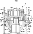
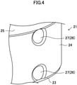
- the housing (21) is fixed to the inner peripheral surface of the casing (10). As illustrated in FIGS. 3 and 4 , the housing (21) includes a bearing portion (22), a body portion (23), a pressing portion (24), a supporting portion (25), and a plurality of weld portions (26).
- the bearing portion (22) has a substantially cylindrical shape.
- the bearing portion (22) rotatably supports the drive shaft (60).
- An upper face of the bearing portion (22) has an elastic groove (22a) that enables elastic deformation of the bearing portion (22).
- the body portion (23) is continuous with the bearing portion (22) and extends radially outward.
- the body portion (23) has a thick cylindrical shape.
- the radial thickness of the body portion (23) is greater than the radial thickness of the supporting portion (25).
- the pressing portion (24) is provided radially outside the body portion (23).
- the outer peripheral surface of the pressing portion (24) constitutes a portion of the outer peripheral surface of the housing (21).
- the pressing portion (24) has a smaller axial length (vertical length) than the housing (21). The pressing portion (24) is pressed against and fixed to the barrel of the casing (10).
- the supporting portion (25) extends from an upper face of the body portion (23) (in other words, a face of the body portion (23) near the fixed scroll (30) in the axial direction of the casing (10)) toward the fixed scroll (30).
- the supporting portion (25) has a somewhat thin cylindrical shape.
- An upper end face of the supporting portion (25) (in other words, an end face of the supporting portion (25) near the fixed scroll (30)) is a fastening face (25a) to which the fixed scroll (30) is fastened.
- the weld portions (26) are configured as recesses (27) formed on the outer peripheral surface of the housing (21).
- Welding pins (28) are provided in the recesses (27). The welding pins (28) melt when welded via welding through holes (13) formed in the casing (10), thereby fixing the housing (21) and the casing (10) together.
- weld portions (26) are arranged in the axial direction of the casing (10) ( FIG. 3 ). Two or more (four in this example) weld portions (26) are arranged in the circumferential direction of the casing (10) ( FIG. 5 ).
- a first gap (G1) is formed between the outer peripheral surface of the housing (21) (specifically, the body portion (23) and the supporting portion (25)) and the inner peripheral surface of the casing (10) above the pressing portion (24).
- a second gap (G2) is formed between the outer peripheral surface of the fixed scroll (30) and the inner peripheral surface of the casing (10).
- the outer peripheral surface of the fixed scroll (30) is substantially flush with the outer peripheral surface of the supporting portion (25).
- the first gap (G1) and the second gap (G2) allow the upper ones of the weld portions (26) to communicate with the first space (S1).
- the first gap (G1) constitutes a gap.
- the axial length (L1) of the first gap (G1) is greater than the axial length (L2) of the inner peripheral surface of the supporting portion (25).
- the axial distance between the upper end face (fastening face (25a)) of the supporting portion (25) and the upper end of the pressing portion (24) is longer than the axial distance between the upper end face of the supporting portion (25) and the upper face of the body portion (23). That is to say, the upper end of the pressing portion (24) is located below the upper face of the body portion (23). Further, the lower end of the pressing portion (24) is located above the lower face of the body portion (23).
- the entire pressing portion (24) and the body portion (23) are arranged side by side in the radial direction of the casing (10).
- a third gap (G3) is formed between the outer peripheral surface of the housing (21) (specifically, the body portion (23)) and the inner peripheral surface of the casing (10) below the pressing portion (24).
- the third gap (G3) allows lower ones of the weld portions (26) to communicate with the second space (S2).
- At least part of the pressing portion (24) and at least part of the weld portion (26) are arranged side by side in the circumferential direction of the casing (10). At least part of the pressing portion (24) and at least part of the weld portion (26) (the recess (27)) are arranged so as to be close to each other in the circumferential direction of the casing (10). At least part of the pressing portion (24) and at least part of the weld portion (26) (the recess (27)) are arranged so as to substantially adjoin each other in the circumferential direction of the casing (10).
- At least part of the pressing portion (24) and at least part of the weld portion (26) (the recess (27)) are arranged side by side in the axial direction of the casing (10). At least part of the pressing portion (24) and at least part of the weld portion (26) (the recess (27)) are arranged so as to be close to each other in the axial direction of the casing (10). At least part of the pressing portion (24) and at least part of the weld portion (26) (the recess (27)) are arranged so as to substantially adjoin each other in the axial direction of the casing (10).
- At least part of the pressing portion (24) and at least part of the weld portion (26) (the recess (27)) are arranged side by side in the circumferential and axial directions of the casing (10). At least part of the pressing portion (24) and at least part of the weld portion (26) (the recess (27)) are arranged so as to be close to each other in the circumferential and axial directions of the casing (10). At least part of the pressing portion (24) and at least part of the weld portion (26) (the recess (27)) are arranged so as to substantially adjoin each other in the circumferential and axial directions of the casing (10). Thus, the casing (10) and the housing (21) are more firmly fixed to each other.
- the fixed scroll (30) is disposed on one axial side (upper side in this example) of the housing (21).
- the fixed scroll (30) includes a fixed end plate (31), a fixed wrap (32), and an outer peripheral wall (33).
- the fixed end plate (31) has a substantially circular plate shape.
- the fixed wrap (32) is formed in the shape of a spiral wall that shows an involute curve, and protrudes from a front face (lower face in this example) of the fixed end plate (31).
- the outer peripheral wall (33) surrounds the outer periphery of the fixed wrap (32), and protrudes from the front face of the fixed end plate (31).
- the lower face of the outer peripheral wall (33) is fastened to the fastening face (25a) of the supporting portion (25).
- a distal end face (lower end face in this example) of the fixed wrap (32) is substantially flush with a distal end face of the outer peripheral wall (33).
- the outer peripheral wall (33) of the fixed scroll (30) has a suction port (not shown).
- the suction port is connected to a downstream end of the suction pipe (11).
- the fixed end plate (31) of the fixed scroll (30) has, at its center, a discharge port (34) penetrating the fixed end plate (31) in a thickness direction.
- the movable scroll (40) includes a movable end plate (41), a movable wrap (42), and a boss (43).
- the movable end plate (41) has a substantially circular plate shape.
- the movable wrap (42) is formed in the shape of a spiral wall that shows an involute curve, and protrudes from a front face (upper face in this example) of the movable end plate (41).
- the boss (43) is formed in a cylindrical shape, and is positioned at a center portion of a back face (lower face in this example) of the movable end plate (41).
- the movable wrap (42) of the movable scroll (40) meshes with the fixed wrap (32) of the fixed scroll (30).
- This configuration provides a compression chamber (S20) between the fixed scroll (30) and the movable scroll (40).
- the compression chamber (S20) is a space for compressing a fluid.
- the compression chamber (S20) is configured to compress a fluid sucked from the suction pipe (11) through the suction port, and discharge the compressed fluid through the discharge port (34).
- the scroll compressor (1) includes: a casing (10) having a cylindrical shape; a compression mechanism (20) housed in the casing (10) and including a fixed scroll (30), a movable scroll (40), and a housing (21); and a drive shaft (60) configured to rotate the movable scroll (40), wherein the housing (21) includes: a bearing portion (22) configured to rotatably support the drive shaft (60); a body portion (23) continuous with the bearing portion (22) and extending radially outward; a pressing portion (24) provided radially outside the body portion (23) to press the casing (10); and a supporting portion (25) extending from a face of the body portion (23) near the fixed scroll (30) in an axial direction toward the fixed scroll (30), an end face of the supporting portion (25) near the fixed scroll (30) is a fastening face (25a) to which the fixed scroll (30) is fastened, a gap (G1) is formed between an inner peripheral surface of the casing (10) and outer peripheral surfaces of the body portion (23) and the housing (21)
- the housing (21) is fixed to the casing (10) by the pressing portion (24).
- the end face of the supporting portion (25) near the fixed scroll (30) is the fastening face (25a) to which the fixed scroll (30) is fastened.
- the pressing portion (24) and the supporting portion (25) are connected to each other through the body portion (23). Pressure from the casing (10) acts radially on the pressing portion (24).
- the gap (G1) is formed between the supporting portion (25) and the casing (10), pressure from the casing (10) does not act directly on the supporting portion (25).
- the position of the supporting portion (25) may vary between before and after the fixing of the housing (21) to the casing (10) due to the pressure acting on the pressing portion (24). A large amount of such variation in the position reduces the sealing performance between the fastening face (25a) and the fixed scroll (30).
- the axial length (L1) of the gap (G1) is greater than or equal to the axial length (L2) of the inner peripheral surface of the supporting portion (25).
- the axial distance between a face (upper face in this example) of the body portion (23) near the fixed scroll (30) and the fixed scroll (30) is shorter than or equal to the axial distance between an end (upper end in this example) of the pressing portion (24) near the fixed scroll (30) and the fixed scroll (30).
- the radial pressure applied from the casing (10) to the pressing portion (24) is securely received by the body portion (23) extending radially.
- the scroll compressor (1) of this embodiment is configured such that the axial length (L1) of the gap (G1) is greater than the axial length (L2) of the inner peripheral surface of the supporting portion (25). This configuration further reduces the variation in the position of the supporting portion (25), and further enhances the sealing performance between the fastening face (25a) and the fixed scroll (30). It is therefore possible to further improve the efficiency of the scroll compressor (1).
- the scroll compressor (1) of this embodiment is configured such that the radial thickness of the body portion (23) is greater than the radial thickness of the supporting portion (25). Thus, the radial pressure applied from the casing (10) to the pressing portion (24) is securely received by the body portion (23) with a greater radial thickness.
- the scroll compressor (1) of this embodiment is configured such that the housing (21) has a weld portion (26) welded to the casing (10), and that at least part of the pressing portion (24) and at least part of the weld portion (26) are arranged side by side in a circumferential direction of the casing (10).
- This configuration can downsize the housing (21) in the axial direction of the casing (10), and in turn, can downsize the scroll compressor (1), compared to a configuration in which the pressing portion (24) and the weld portion (26) are arranged side by side in the axial direction of the casing (10).
- the scroll compressor (1) of this embodiment is configured such that the weld portion (26) communicates with an internal space of the casing (10) through the gap (G1). This configuration allows welding gas to be released into the internal space of the casing (10) through the gap (G1) when the housing (21) is welded to the casing (10), thereby reducing poor welding.
- the axial length (L1) of the first gap (G1) may be equal to the axial length (L2) of the inner peripheral surface of the supporting portion (25).
- the number and arrangement of the weld portions (26) should not be limited to those in the foregoing embodiment, and can be optionally determined.
- the present disclosure is useful for a scroll compressor and a refrigeration apparatus including the scroll compressor.
Landscapes
- Engineering & Computer Science (AREA)
- Mechanical Engineering (AREA)
- General Engineering & Computer Science (AREA)
- Rotary Pumps (AREA)
- Applications Or Details Of Rotary Compressors (AREA)
Abstract
Description
- The present disclosure relates to a scroll compressor and a refrigeration apparatus including the same.
- Scroll compressors including a casing and a compression mechanism having a fixed scroll and a housing have been known (e.g., Patent Document 1). A housing of a scroll compressor of this document has a pressing portion that is pressed against a casing, and a supporting portion connected to the pressing portion and extending axially. An end face of the supporting portion near a fixed scroll is a fastening face to which the fixed scroll is fastened.
- Patent Document 1:
Japanese Unexamined Patent Publication No. 2017-25762 - Since the pressing portion is pressed against the casing, the position of the supporting portion connected to the pressing portion may vary between before and after fixing of the housing to the casing. A large amount of variation in this position reduces the sealing performance between the fixed scroll and the fastening face of the supporting portion and reduces the efficiency of the scroll compressor.
- It is an object of the present disclosure to improve the efficiency of a scroll compressor.
- A first aspect of the present disclosure is directed to a scroll compressor (1). The scroll compressor (1) includes: a casing (10) having a cylindrical shape; a compression mechanism (20) housed in the casing (10) and including a fixed scroll (30), a movable scroll (40), and a housing (21); and a drive shaft (60) configured to rotate the movable scroll (40), wherein the housing (21) includes: a bearing portion (22) configured to rotatably support the drive shaft (60); a body portion (23) continuous with the bearing portion (22) and extending radially outward; a pressing portion (24) provided radially outside the body portion (23) to press the casing (10); and a supporting portion (25) extending from a face of the body portion (23) near the fixed scroll (30) in an axial direction toward the fixed scroll (30), an end face of the supporting portion (25) near the fixed scroll (30) is a fastening face (25a) to which the fixed scroll (30) is fastened, a gap (G1) is formed between an inner peripheral surface of the casing (10) and outer peripheral surfaces of the body portion (23) and the supporting portion (25), and an axial length (L1) of the gap (G1) is greater than or equal to an axial length (L2) of an inner peripheral surface of the supporting portion (25).
- According to the first aspect, the radial pressure applied from the casing (10) to the pressing portion (24) is securely received by the body portion (23) extending radially. This configuration reduces the variation in the position of the supporting portion (25), and enhances the sealing performance between the fastening face (25a) and the fixed scroll (30). It is therefore possible to improve the efficiency of the scroll compressor (1).
- A second aspect of the present disclosure is an embodiment of the first aspect. In the second aspect, the axial length (L1) of the gap (G1) is greater than the axial length (L2) of the inner peripheral surface of the supporting portion (25).
- This configuration of the second aspect further reduces the variation in the position of the supporting portion (25), and further enhances the sealing performance between the fastening face (25a) and the fixed scroll (30). It is therefore possible to further improve the efficiency of the scroll compressor (1).
- A third aspect of the present disclosure is an embodiment of the first or second aspect. In the third aspect, the housing (21) has a weld portion (26) welded to the casing (10), and at least part of the pressing portion (24) and at least part of the weld portion (26) are arranged side by side in a circumferential direction of the casing (10).
- Compared to a configuration in which the pressing portion (24) and the weld portion (26) are arranged side by side in the axial direction, this configuration of the third aspect can downsize the housing (21) in the axial direction, and in turn, can downsize the scroll compressor (1).
- A fourth aspect of the present disclosure is an embodiment of the third aspect. In the fourth aspect, the weld portion (26) communicates with an internal space of the casing (10) through the gap (G1).
- This configuration of the fourth aspect allows welding gas to be released into the internal space of the casing (10) through the gap (G1) when the housing (21) is welded to the casing (10), thereby reducing poor welding.
- A fifth aspect of the present disclosure is directed to a refrigeration apparatus (100). The refrigeration apparatus (100) includes the scroll compressor (1) of any one of the first to fourth aspects.
-
-
FIG. 1 is a refrigerant circuit diagram showing a schematic configuration of a refrigeration apparatus according to an embodiment. -
FIG. 2 is a vertical cross-sectional view of a scroll compressor according to the embodiment. -
FIG. 3 is a vertical cross-sectional view illustrating an essential portion of the scroll compressor according to the embodiment. -
FIG. 4 is a perspective view illustrating an essential portion of a housing according to the embodiment. -
FIG. 5 is a schematic plan view of the scroll compressor according to the embodiment. - An embodiment will be described. A scroll compressor (1) according to this embodiment is used for a refrigeration apparatus (100). Examples of the refrigeration apparatus (100) include an air conditioner that adjusts the temperature and humidity of air, a cooling apparatus that cools its internal space, and a hot water supply apparatus that produces hot water.
- As shown in
FIG. 1 , the refrigeration apparatus (100) includes a refrigerant circuit (101) that performs a refrigeration cycle. The refrigerant circuit (101) includes the scroll compressor (1), a condenser (102), an expansion mechanism (103), and an evaporator (104). In the refrigerant circuit (101), a refrigerant compressed by the scroll compressor (1) dissipates heat in the condenser (102) and is decompressed in the expansion mechanism (103). The decompressed refrigerant evaporates in the evaporator (104), and is sucked into the scroll compressor (1). - As illustrated in
FIGS. 2 and3 , the scroll compressor (1) includes a casing (10), a compression mechanism (20), an electric motor (50), and a drive shaft (60). - The casing (10) is in the shape of a vertically long cylinder with both ends closed. The casing (10) houses therein the compression mechanism (20) and the electric motor (50) sequentially arranged from top. The drive shaft (60) extending in the casing (10) in an axial direction (vertical direction) connects the compression mechanism (20) and the electric motor (50).
- The casing (10) is provided with a suction pipe (11) and a discharge pipe (12). The suction pipe (11) passes through an upper portion of the casing (10) in the axial direction so as to be connected to the compression mechanism (20). The suction pipe (11) introduces a low-pressure fluid (for example, a gas refrigerant) into the compression mechanism (20). The discharge pipe (12) passes through the barrel of the casing (10) in a radial direction to communicate with the internal space of the casing (10). The discharge pipe (12) introduces a high-pressure fluid in the casing (10) out of the casing (10).
- The compression mechanism (20) is housed in the casing (10). The compression mechanism (20) is configured to compress the fluid introduced through the suction pipe (11) and discharge the compressed fluid into the casing (10). The configuration of the compression mechanism (20) will be described in detail.
- The electric motor (50) is housed in the casing (10), and is disposed below the compression mechanism (20). The electric motor (50) includes a stator (51) and a rotor (52). The stator (51) is substantially in the shape of a cylinder, and is fixed to the casing (10). The rotor (52) is inserted in the stator (51) to be rotatable on the inner periphery of the stator (51). The drive shaft (60) is inserted through, and fixed to, the inner circumference of the rotor (52).
- The drive shaft (60) has a main shaft portion (61) and an eccentric shaft portion (62). The main shaft portion (61) extends in the axial direction (vertical direction) of the casing (10). The eccentric shaft portion (62) is provided at an upper end of the main shaft portion (61). The outer diameter of the eccentric shaft portion (62) is smaller than that of the main shaft portion (61). The eccentric shaft portion (62) has an axis decentered by a predetermined distance with respect to the axis of the main shaft portion (61).
- Next, the configuration of the compression mechanism (20) will be described with reference to
FIGS. 2 to 5 . - As illustrated in
FIGS. 2 and3 , the compression mechanism (20) includes a housing (21), a fixed scroll (30), and a movable scroll (40). The housing (21) is provided in the casing (10). The fixed scroll (30) is fixed to the housing (21). The movable scroll (40) is disposed between the housing (21) and the fixed scroll (30). The movable scroll (40) is configured to mesh with the fixed scroll (30) and rotate eccentrically relative to the fixed scroll (30). - The housing (21) is fixed in the casing (10), and partitions the internal space of the casing (10) into two spaces in the axial direction. One of the spaces above the housing (21) constitutes a first space (S1). The other space below the housing (21) constitutes a second space (S2). The first space (S1) constitutes an internal space.
- The housing (21) is fixed to the inner peripheral surface of the casing (10). As illustrated in
FIGS. 3 and4 , the housing (21) includes a bearing portion (22), a body portion (23), a pressing portion (24), a supporting portion (25), and a plurality of weld portions (26). - The bearing portion (22) has a substantially cylindrical shape. The bearing portion (22) rotatably supports the drive shaft (60). An upper face of the bearing portion (22) has an elastic groove (22a) that enables elastic deformation of the bearing portion (22).
- The body portion (23) is continuous with the bearing portion (22) and extends radially outward. The body portion (23) has a thick cylindrical shape. The radial thickness of the body portion (23) is greater than the radial thickness of the supporting portion (25).
- The pressing portion (24) is provided radially outside the body portion (23). The outer peripheral surface of the pressing portion (24) constitutes a portion of the outer peripheral surface of the housing (21). The pressing portion (24) has a smaller axial length (vertical length) than the housing (21). The pressing portion (24) is pressed against and fixed to the barrel of the casing (10).
- The supporting portion (25) extends from an upper face of the body portion (23) (in other words, a face of the body portion (23) near the fixed scroll (30) in the axial direction of the casing (10)) toward the fixed scroll (30). The supporting portion (25) has a somewhat thin cylindrical shape. An upper end face of the supporting portion (25) (in other words, an end face of the supporting portion (25) near the fixed scroll (30)) is a fastening face (25a) to which the fixed scroll (30) is fastened.
- The weld portions (26) are configured as recesses (27) formed on the outer peripheral surface of the housing (21). Welding pins (28) are provided in the recesses (27). The welding pins (28) melt when welded via welding through holes (13) formed in the casing (10), thereby fixing the housing (21) and the casing (10) together.
- Two or more (two in this example) weld portions (26) are arranged in the axial direction of the casing (10) (
FIG. 3 ). Two or more (four in this example) weld portions (26) are arranged in the circumferential direction of the casing (10) (FIG. 5 ). - A first gap (G1) is formed between the outer peripheral surface of the housing (21) (specifically, the body portion (23) and the supporting portion (25)) and the inner peripheral surface of the casing (10) above the pressing portion (24). A second gap (G2) is formed between the outer peripheral surface of the fixed scroll (30) and the inner peripheral surface of the casing (10). The outer peripheral surface of the fixed scroll (30) is substantially flush with the outer peripheral surface of the supporting portion (25). The first gap (G1) and the second gap (G2) allow the upper ones of the weld portions (26) to communicate with the first space (S1). The first gap (G1) constitutes a gap.
- The axial length (L1) of the first gap (G1) is greater than the axial length (L2) of the inner peripheral surface of the supporting portion (25). In other words, the axial distance between the upper end face (fastening face (25a)) of the supporting portion (25) and the upper end of the pressing portion (24) is longer than the axial distance between the upper end face of the supporting portion (25) and the upper face of the body portion (23). That is to say, the upper end of the pressing portion (24) is located below the upper face of the body portion (23). Further, the lower end of the pressing portion (24) is located above the lower face of the body portion (23). Thus, the entire pressing portion (24) and the body portion (23) are arranged side by side in the radial direction of the casing (10).
- A third gap (G3) is formed between the outer peripheral surface of the housing (21) (specifically, the body portion (23)) and the inner peripheral surface of the casing (10) below the pressing portion (24). The third gap (G3) allows lower ones of the weld portions (26) to communicate with the second space (S2).
- As illustrated in
FIGS. 3 and4 , at least part of the pressing portion (24) and at least part of the weld portion (26) (the recess (27)) are arranged side by side in the circumferential direction of the casing (10). At least part of the pressing portion (24) and at least part of the weld portion (26) (the recess (27)) are arranged so as to be close to each other in the circumferential direction of the casing (10). At least part of the pressing portion (24) and at least part of the weld portion (26) (the recess (27)) are arranged so as to substantially adjoin each other in the circumferential direction of the casing (10). - At least part of the pressing portion (24) and at least part of the weld portion (26) (the recess (27)) are arranged side by side in the axial direction of the casing (10). At least part of the pressing portion (24) and at least part of the weld portion (26) (the recess (27)) are arranged so as to be close to each other in the axial direction of the casing (10). At least part of the pressing portion (24) and at least part of the weld portion (26) (the recess (27)) are arranged so as to substantially adjoin each other in the axial direction of the casing (10).
- Thus, at least part of the pressing portion (24) and at least part of the weld portion (26) (the recess (27)) are arranged side by side in the circumferential and axial directions of the casing (10). At least part of the pressing portion (24) and at least part of the weld portion (26) (the recess (27)) are arranged so as to be close to each other in the circumferential and axial directions of the casing (10). At least part of the pressing portion (24) and at least part of the weld portion (26) (the recess (27)) are arranged so as to substantially adjoin each other in the circumferential and axial directions of the casing (10). Thus, the casing (10) and the housing (21) are more firmly fixed to each other.
- The fixed scroll (30) is disposed on one axial side (upper side in this example) of the housing (21). The fixed scroll (30) includes a fixed end plate (31), a fixed wrap (32), and an outer peripheral wall (33).
- The fixed end plate (31) has a substantially circular plate shape. The fixed wrap (32) is formed in the shape of a spiral wall that shows an involute curve, and protrudes from a front face (lower face in this example) of the fixed end plate (31). The outer peripheral wall (33) surrounds the outer periphery of the fixed wrap (32), and protrudes from the front face of the fixed end plate (31). The lower face of the outer peripheral wall (33) is fastened to the fastening face (25a) of the supporting portion (25). A distal end face (lower end face in this example) of the fixed wrap (32) is substantially flush with a distal end face of the outer peripheral wall (33).
- The outer peripheral wall (33) of the fixed scroll (30) has a suction port (not shown). The suction port is connected to a downstream end of the suction pipe (11). The fixed end plate (31) of the fixed scroll (30) has, at its center, a discharge port (34) penetrating the fixed end plate (31) in a thickness direction.
- The movable scroll (40) includes a movable end plate (41), a movable wrap (42), and a boss (43).
- The movable end plate (41) has a substantially circular plate shape. The movable wrap (42) is formed in the shape of a spiral wall that shows an involute curve, and protrudes from a front face (upper face in this example) of the movable end plate (41). The boss (43) is formed in a cylindrical shape, and is positioned at a center portion of a back face (lower face in this example) of the movable end plate (41). The movable wrap (42) of the movable scroll (40) meshes with the fixed wrap (32) of the fixed scroll (30).
- This configuration provides a compression chamber (S20) between the fixed scroll (30) and the movable scroll (40). The compression chamber (S20) is a space for compressing a fluid. The compression chamber (S20) is configured to compress a fluid sucked from the suction pipe (11) through the suction port, and discharge the compressed fluid through the discharge port (34).
- The scroll compressor (1) according to this embodiment includes: a casing (10) having a cylindrical shape; a compression mechanism (20) housed in the casing (10) and including a fixed scroll (30), a movable scroll (40), and a housing (21); and a drive shaft (60) configured to rotate the movable scroll (40), wherein the housing (21) includes: a bearing portion (22) configured to rotatably support the drive shaft (60); a body portion (23) continuous with the bearing portion (22) and extending radially outward; a pressing portion (24) provided radially outside the body portion (23) to press the casing (10); and a supporting portion (25) extending from a face of the body portion (23) near the fixed scroll (30) in an axial direction toward the fixed scroll (30), an end face of the supporting portion (25) near the fixed scroll (30) is a fastening face (25a) to which the fixed scroll (30) is fastened, a gap (G1) is formed between an inner peripheral surface of the casing (10) and outer peripheral surfaces of the body portion (23) and the supporting portion (25), and an axial length (L1) of the gap (G1) is greater than or equal to an axial length (L2) of an inner peripheral surface of the supporting portion (25). Thus, the housing (21) is fixed to the casing (10) by the pressing portion (24). The end face of the supporting portion (25) near the fixed scroll (30) is the fastening face (25a) to which the fixed scroll (30) is fastened. The pressing portion (24) and the supporting portion (25) are connected to each other through the body portion (23). Pressure from the casing (10) acts radially on the pressing portion (24). On the other hand, since the gap (G1) is formed between the supporting portion (25) and the casing (10), pressure from the casing (10) does not act directly on the supporting portion (25). However, since the supporting portion (25) is continuous with the pressing portion (24), the position of the supporting portion (25) may vary between before and after the fixing of the housing (21) to the casing (10) due to the pressure acting on the pressing portion (24). A large amount of such variation in the position reduces the sealing performance between the fastening face (25a) and the fixed scroll (30). To address this, in this embodiment, the axial length (L1) of the gap (G1) is greater than or equal to the axial length (L2) of the inner peripheral surface of the supporting portion (25). In other words, the axial distance between a face (upper face in this example) of the body portion (23) near the fixed scroll (30) and the fixed scroll (30) is shorter than or equal to the axial distance between an end (upper end in this example) of the pressing portion (24) near the fixed scroll (30) and the fixed scroll (30). Thus, the radial pressure applied from the casing (10) to the pressing portion (24) is securely received by the body portion (23) extending radially. This configuration reduces the variation in the position of the supporting portion (25), and enhances the sealing performance between the fastening face (25a) and the fixed scroll (30). It is therefore possible to improve the efficiency of the scroll compressor (1).
- The scroll compressor (1) of this embodiment is configured such that the axial length (L1) of the gap (G1) is greater than the axial length (L2) of the inner peripheral surface of the supporting portion (25). This configuration further reduces the variation in the position of the supporting portion (25), and further enhances the sealing performance between the fastening face (25a) and the fixed scroll (30). It is therefore possible to further improve the efficiency of the scroll compressor (1).
- The scroll compressor (1) of this embodiment is configured such that the radial thickness of the body portion (23) is greater than the radial thickness of the supporting portion (25). Thus, the radial pressure applied from the casing (10) to the pressing portion (24) is securely received by the body portion (23) with a greater radial thickness.
- The scroll compressor (1) of this embodiment is configured such that the housing (21) has a weld portion (26) welded to the casing (10), and that at least part of the pressing portion (24) and at least part of the weld portion (26) are arranged side by side in a circumferential direction of the casing (10). This configuration can downsize the housing (21) in the axial direction of the casing (10), and in turn, can downsize the scroll compressor (1), compared to a configuration in which the pressing portion (24) and the weld portion (26) are arranged side by side in the axial direction of the casing (10).
- The scroll compressor (1) of this embodiment is configured such that the weld portion (26) communicates with an internal space of the casing (10) through the gap (G1). This configuration allows welding gas to be released into the internal space of the casing (10) through the gap (G1) when the housing (21) is welded to the casing (10), thereby reducing poor welding.
- The foregoing embodiment may be modified as follows.
- For example, the axial length (L1) of the first gap (G1) may be equal to the axial length (L2) of the inner peripheral surface of the supporting portion (25).
- Further, for example, the number and arrangement of the weld portions (26) should not be limited to those in the foregoing embodiment, and can be optionally determined.
- While embodiments and variations have been described above, it will be understood that various modifications in form and detail may be made without departing from the spirit and scope of the present disclosure as set forth in the appended claims. The foregoing embodiments and variations thereof may be combined and replaced with each other without deteriorating the intended functions of the present disclosure.
- As can be seen from the foregoing description, the present disclosure is useful for a scroll compressor and a refrigeration apparatus including the scroll compressor.
-
- 1
- Scroll Compressor
- 10
- Casing
- 20
- Compression Mechanism
- 21
- Housing
- 22
- Bearing Portion
- 23
- Body Portion
- 24
- Pressing Portion
- 25
- Supporting Portion
- 25a
- Fastening Face
- 26
- Weld Portion
- 30
- Fixed Scroll
- 40
- Movable Scroll
- 60
- Drive Shaft
- 100
- Refrigeration Apparatus
- G1
- First Gap (Gap)
- L1, L2
- Axial Length
- S1
- First Space (Internal Space)
Claims (5)
- A scroll compressor comprising:a casing (10) having a cylindrical shape;a compression mechanism (20) housed in the casing (10) and including a fixed scroll (30), a movable scroll (40), and a housing (21); anda drive shaft (60) configured to rotate the movable scroll (40), whereinthe housing (21) includes:a bearing portion (22) configured to rotatably support the drive shaft (60);a body portion (23) continuous with the bearing portion (22) and extending radially outward;a pressing portion (24) provided radially outside the body portion (23) to press the casing (10); anda supporting portion (25) extending from a face of the body portion (23) near the fixed scroll (30) in an axial direction toward the fixed scroll (30),an end face of the supporting portion (25) near the fixed scroll (30) is a fastening face (25a) to which the fixed scroll (30) is fastened,a gap (G1) is formed between an inner peripheral surface of the casing (10) and outer peripheral surfaces of the body portion (23) and the supporting portion (25), andan axial length (L1) of the gap (G1) is greater than or equal to an axial length (L2) of an inner peripheral surface of the supporting portion (25).
- The scroll compressor of claim 1, wherein
the axial length (L1) of the gap (G1) is greater than the axial length (L2) of the inner peripheral surface of the supporting portion (25). - The scroll compressor of claim 1 or 2, whereinthe housing (21) has a weld portion (26) welded to the casing (10), andat least part of the pressing portion (24) and at least part of the weld portion (26) are arranged side by side in a circumferential direction of the casing (10).
- The scroll compressor of claim 3, wherein
the weld portion (26) communicates with an internal space (S1) of the casing (10) through the gap (G1). - A refrigeration apparatus comprising the scroll compressor (1) of any one of claims 1 to 4.
Applications Claiming Priority (2)
| Application Number | Priority Date | Filing Date | Title |
|---|---|---|---|
| JP2019094994A JP6863405B2 (en) | 2019-05-21 | 2019-05-21 | Scroll compressor and refrigerator equipped with it |
| PCT/JP2020/016603 WO2020235271A1 (en) | 2019-05-21 | 2020-04-15 | Scroll compressor and refrigeration device provided with same |
Publications (3)
| Publication Number | Publication Date |
|---|---|
| EP3940233A1 true EP3940233A1 (en) | 2022-01-19 |
| EP3940233A4 EP3940233A4 (en) | 2022-06-08 |
| EP3940233B1 EP3940233B1 (en) | 2024-04-10 |
Family
ID=73453487
Family Applications (1)
| Application Number | Title | Priority Date | Filing Date |
|---|---|---|---|
| EP20810215.2A Active EP3940233B1 (en) | 2019-05-21 | 2020-04-15 | Scroll compressor and refrigeration device provided with same |
Country Status (6)
| Country | Link |
|---|---|
| US (1) | US11879456B2 (en) |
| EP (1) | EP3940233B1 (en) |
| JP (1) | JP6863405B2 (en) |
| CN (1) | CN113677893B (en) |
| ES (1) | ES2979978T3 (en) |
| WO (1) | WO2020235271A1 (en) |
Families Citing this family (2)
| Publication number | Priority date | Publication date | Assignee | Title |
|---|---|---|---|---|
| CN116420025B (en) * | 2021-02-15 | 2026-01-27 | 松下知识产权经营株式会社 | Compressor and apparatus |
| EP4303442B1 (en) * | 2021-03-01 | 2025-08-27 | Daikin Industries, Ltd. | Compressor and refrigeration cycle device |
Family Cites Families (22)
| Publication number | Priority date | Publication date | Assignee | Title |
|---|---|---|---|---|
| JPS6444389U (en) * | 1987-09-09 | 1989-03-16 | ||
| JP2782858B2 (en) * | 1989-10-31 | 1998-08-06 | 松下電器産業株式会社 | Scroll gas compressor |
| CN1075170C (en) | 1994-02-01 | 2001-11-21 | 三菱重工业株式会社 | Vortex hydraulic mechanism |
| JPH07217554A (en) * | 1994-02-01 | 1995-08-15 | Mitsubishi Heavy Ind Ltd | Scroll type fluid machinery |
| JP3806507B2 (en) * | 1998-03-19 | 2006-08-09 | 三洋電機株式会社 | Scroll compressor |
| US7195468B2 (en) * | 2004-12-13 | 2007-03-27 | Lg Electronics Inc. | Scroll compressor having frame fixing structure and frame fixing method thereof |
| JP5114710B2 (en) * | 2007-10-16 | 2013-01-09 | 株式会社前川製作所 | Hermetic scroll compressor and method for assembling the same |
| JP5362239B2 (en) * | 2008-03-19 | 2013-12-11 | 三洋電機株式会社 | Scroll compressor |
| US8235690B2 (en) | 2008-03-19 | 2012-08-07 | Sanyo Electric Co., Ltd. | Scroll compressor with improved oil separation from refrigerant gas |
| JP5247194B2 (en) * | 2008-03-19 | 2013-07-24 | 三洋電機株式会社 | Scroll compressor |
| JP5247195B2 (en) * | 2008-03-19 | 2013-07-24 | 三洋電機株式会社 | Scroll compressor |
| KR101480464B1 (en) * | 2008-10-15 | 2015-01-09 | 엘지전자 주식회사 | Scroll compressor and refrigeration equipment using it |
| JP5535511B2 (en) * | 2009-03-31 | 2014-07-02 | 三菱重工業株式会社 | Method for manufacturing hermetic fluid machine and hermetic fluid machine |
| JP2010265845A (en) * | 2009-05-15 | 2010-11-25 | Denso Corp | Compressor manufacturing method and compressor |
| KR101462941B1 (en) * | 2012-03-07 | 2014-11-19 | 엘지전자 주식회사 | Horizontal type scroll compressor |
| JP5935579B2 (en) * | 2012-07-31 | 2016-06-15 | ジョンソンコントロールズ ヒタチ エア コンディショニング テクノロジー(ホンコン)リミテッド | Positive displacement compressor |
| JP6195466B2 (en) * | 2013-05-08 | 2017-09-13 | 三菱電機株式会社 | Scroll compressor |
| JP6200819B2 (en) * | 2014-01-22 | 2017-09-20 | ジョンソンコントロールズ ヒタチ エア コンディショニング テクノロジー(ホンコン)リミテッド | Scroll compressor |
| WO2016162912A1 (en) * | 2015-04-06 | 2016-10-13 | 三菱電機株式会社 | Scroll compressor |
| JP2017025762A (en) | 2015-07-21 | 2017-02-02 | ダイキン工業株式会社 | Compressor |
| KR102481368B1 (en) * | 2016-04-26 | 2022-12-26 | 엘지전자 주식회사 | Scroll compressor |
| JP6791302B2 (en) * | 2019-05-21 | 2020-11-25 | ダイキン工業株式会社 | Compressor |
-
2019
- 2019-05-21 JP JP2019094994A patent/JP6863405B2/en active Active
-
2020
- 2020-04-15 CN CN202080028419.1A patent/CN113677893B/en active Active
- 2020-04-15 WO PCT/JP2020/016603 patent/WO2020235271A1/en not_active Ceased
- 2020-04-15 EP EP20810215.2A patent/EP3940233B1/en active Active
- 2020-04-15 ES ES20810215T patent/ES2979978T3/en active Active
-
2021
- 2021-11-10 US US17/523,612 patent/US11879456B2/en active Active
Also Published As
| Publication number | Publication date |
|---|---|
| US20220065250A1 (en) | 2022-03-03 |
| JP6863405B2 (en) | 2021-04-21 |
| CN113677893A (en) | 2021-11-19 |
| JP2020190217A (en) | 2020-11-26 |
| EP3940233B1 (en) | 2024-04-10 |
| EP3940233A4 (en) | 2022-06-08 |
| CN113677893B (en) | 2022-08-02 |
| ES2979978T3 (en) | 2024-09-27 |
| WO2020235271A1 (en) | 2020-11-26 |
| US11879456B2 (en) | 2024-01-23 |
Similar Documents
| Publication | Publication Date | Title |
|---|---|---|
| US12018684B2 (en) | Compression mechanism housing for a compressor | |
| US11879456B2 (en) | Scroll compressor and refrigeration apparatus including same | |
| JP6661916B2 (en) | Scroll compressor and heat cycle system | |
| US10502209B2 (en) | Scroll compressor and air conditioning apparatus including the same | |
| JP2023091399A (en) | Scroll compressors and air conditioners | |
| JP2005147093A (en) | 2-cylinder hermetic rotary compressor and refrigeration air conditioner | |
| CN116917620A (en) | Compressors and refrigeration cycle devices | |
| JP7634716B2 (en) | Compressor and refrigeration cycle device | |
| CN109153063B (en) | Compressor, manufacturing method of compressor, and pipe expanding device | |
| US10920775B2 (en) | Scroll compressor with different sized gaps formed between inner and outer peripheral surfaces of scroll laps | |
| JP2020193576A (en) | Scroll compressor and refrigerator with the same | |
| KR100549613B1 (en) | Rotary compressor | |
| CN211737453U (en) | Scroll compressor and refrigeration device with same | |
| US11408422B2 (en) | Scroll compressor having an arcuate portion side surface clearance larger than a spiral portion side surface clearance | |
| US12385486B2 (en) | Scroll compressor and refrigeration device | |
| JP7755386B2 (en) | Scroll Compressor | |
| US12031440B2 (en) | Accumulator fixing device for compressor and compressor having the same | |
| CN215170749U (en) | Scroll compressor having a discharge port | |
| JP2026001142A5 (en) | ||
| WO2019123609A1 (en) | Hermetic compressor and refrigeration cycle device |
Legal Events
| Date | Code | Title | Description |
|---|---|---|---|
| STAA | Information on the status of an ep patent application or granted ep patent |
Free format text: STATUS: THE INTERNATIONAL PUBLICATION HAS BEEN MADE |
|
| PUAI | Public reference made under article 153(3) epc to a published international application that has entered the european phase |
Free format text: ORIGINAL CODE: 0009012 |
|
| STAA | Information on the status of an ep patent application or granted ep patent |
Free format text: STATUS: REQUEST FOR EXAMINATION WAS MADE |
|
| 17P | Request for examination filed |
Effective date: 20211013 |
|
| AK | Designated contracting states |
Kind code of ref document: A1 Designated state(s): AL AT BE BG CH CY CZ DE DK EE ES FI FR GB GR HR HU IE IS IT LI LT LU LV MC MK MT NL NO PL PT RO RS SE SI SK SM TR |
|
| A4 | Supplementary search report drawn up and despatched |
Effective date: 20220510 |
|
| RIC1 | Information provided on ipc code assigned before grant |
Ipc: F04C 18/02 20060101AFI20220503BHEP |
|
| DAV | Request for validation of the european patent (deleted) | ||
| DAX | Request for extension of the european patent (deleted) | ||
| RAP3 | Party data changed (applicant data changed or rights of an application transferred) |
Owner name: DAIKIN INDUSTRIES, LTD. |
|
| STAA | Information on the status of an ep patent application or granted ep patent |
Free format text: STATUS: EXAMINATION IS IN PROGRESS |
|
| 17Q | First examination report despatched |
Effective date: 20230224 |
|
| P01 | Opt-out of the competence of the unified patent court (upc) registered |
Effective date: 20230525 |
|
| GRAP | Despatch of communication of intention to grant a patent |
Free format text: ORIGINAL CODE: EPIDOSNIGR1 |
|
| STAA | Information on the status of an ep patent application or granted ep patent |
Free format text: STATUS: GRANT OF PATENT IS INTENDED |
|
| INTG | Intention to grant announced |
Effective date: 20231207 |
|
| GRAS | Grant fee paid |
Free format text: ORIGINAL CODE: EPIDOSNIGR3 |
|
| GRAA | (expected) grant |
Free format text: ORIGINAL CODE: 0009210 |
|
| STAA | Information on the status of an ep patent application or granted ep patent |
Free format text: STATUS: THE PATENT HAS BEEN GRANTED |
|
| AK | Designated contracting states |
Kind code of ref document: B1 Designated state(s): AL AT BE BG CH CY CZ DE DK EE ES FI FR GB GR HR HU IE IS IT LI LT LU LV MC MK MT NL NO PL PT RO RS SE SI SK SM TR |
|
| REG | Reference to a national code |
Ref country code: GB Ref legal event code: FG4D |
|
| REG | Reference to a national code |
Ref country code: CH Ref legal event code: EP |
|
| REG | Reference to a national code |
Ref country code: DE Ref legal event code: R096 Ref document number: 602020028874 Country of ref document: DE |
|
| REG | Reference to a national code |
Ref country code: IE Ref legal event code: FG4D |
|
| REG | Reference to a national code |
Ref country code: LT Ref legal event code: MG9D |
|
| REG | Reference to a national code |
Ref country code: NL Ref legal event code: MP Effective date: 20240410 |
|
| REG | Reference to a national code |
Ref country code: AT Ref legal event code: MK05 Ref document number: 1675159 Country of ref document: AT Kind code of ref document: T Effective date: 20240410 |
|
| PG25 | Lapsed in a contracting state [announced via postgrant information from national office to epo] |
Ref country code: NL Free format text: LAPSE BECAUSE OF FAILURE TO SUBMIT A TRANSLATION OF THE DESCRIPTION OR TO PAY THE FEE WITHIN THE PRESCRIBED TIME-LIMIT Effective date: 20240410 |
|
| REG | Reference to a national code |
Ref country code: ES Ref legal event code: FG2A Ref document number: 2979978 Country of ref document: ES Kind code of ref document: T3 Effective date: 20240927 |
|
| PG25 | Lapsed in a contracting state [announced via postgrant information from national office to epo] |
Ref country code: NL Free format text: LAPSE BECAUSE OF FAILURE TO SUBMIT A TRANSLATION OF THE DESCRIPTION OR TO PAY THE FEE WITHIN THE PRESCRIBED TIME-LIMIT Effective date: 20240410 |
|
| PG25 | Lapsed in a contracting state [announced via postgrant information from national office to epo] |
Ref country code: IS Free format text: LAPSE BECAUSE OF FAILURE TO SUBMIT A TRANSLATION OF THE DESCRIPTION OR TO PAY THE FEE WITHIN THE PRESCRIBED TIME-LIMIT Effective date: 20240810 |
|
| PG25 | Lapsed in a contracting state [announced via postgrant information from national office to epo] |
Ref country code: BG Free format text: LAPSE BECAUSE OF FAILURE TO SUBMIT A TRANSLATION OF THE DESCRIPTION OR TO PAY THE FEE WITHIN THE PRESCRIBED TIME-LIMIT Effective date: 20240410 |
|
| PG25 | Lapsed in a contracting state [announced via postgrant information from national office to epo] |
Ref country code: HR Free format text: LAPSE BECAUSE OF FAILURE TO SUBMIT A TRANSLATION OF THE DESCRIPTION OR TO PAY THE FEE WITHIN THE PRESCRIBED TIME-LIMIT Effective date: 20240410 Ref country code: FI Free format text: LAPSE BECAUSE OF FAILURE TO SUBMIT A TRANSLATION OF THE DESCRIPTION OR TO PAY THE FEE WITHIN THE PRESCRIBED TIME-LIMIT Effective date: 20240410 |
|
| PG25 | Lapsed in a contracting state [announced via postgrant information from national office to epo] |
Ref country code: GR Free format text: LAPSE BECAUSE OF FAILURE TO SUBMIT A TRANSLATION OF THE DESCRIPTION OR TO PAY THE FEE WITHIN THE PRESCRIBED TIME-LIMIT Effective date: 20240711 |
|
| PG25 | Lapsed in a contracting state [announced via postgrant information from national office to epo] |
Ref country code: PT Free format text: LAPSE BECAUSE OF FAILURE TO SUBMIT A TRANSLATION OF THE DESCRIPTION OR TO PAY THE FEE WITHIN THE PRESCRIBED TIME-LIMIT Effective date: 20240812 |
|
| PG25 | Lapsed in a contracting state [announced via postgrant information from national office to epo] |
Ref country code: AT Free format text: LAPSE BECAUSE OF FAILURE TO SUBMIT A TRANSLATION OF THE DESCRIPTION OR TO PAY THE FEE WITHIN THE PRESCRIBED TIME-LIMIT Effective date: 20240410 |
|
| PG25 | Lapsed in a contracting state [announced via postgrant information from national office to epo] |
Ref country code: PL Free format text: LAPSE BECAUSE OF FAILURE TO SUBMIT A TRANSLATION OF THE DESCRIPTION OR TO PAY THE FEE WITHIN THE PRESCRIBED TIME-LIMIT Effective date: 20240410 |
|
| PG25 | Lapsed in a contracting state [announced via postgrant information from national office to epo] |
Ref country code: LV Free format text: LAPSE BECAUSE OF FAILURE TO SUBMIT A TRANSLATION OF THE DESCRIPTION OR TO PAY THE FEE WITHIN THE PRESCRIBED TIME-LIMIT Effective date: 20240410 |
|
| PG25 | Lapsed in a contracting state [announced via postgrant information from national office to epo] |
Ref country code: PT Free format text: LAPSE BECAUSE OF FAILURE TO SUBMIT A TRANSLATION OF THE DESCRIPTION OR TO PAY THE FEE WITHIN THE PRESCRIBED TIME-LIMIT Effective date: 20240812 Ref country code: PL Free format text: LAPSE BECAUSE OF FAILURE TO SUBMIT A TRANSLATION OF THE DESCRIPTION OR TO PAY THE FEE WITHIN THE PRESCRIBED TIME-LIMIT Effective date: 20240410 Ref country code: NO Free format text: LAPSE BECAUSE OF FAILURE TO SUBMIT A TRANSLATION OF THE DESCRIPTION OR TO PAY THE FEE WITHIN THE PRESCRIBED TIME-LIMIT Effective date: 20240710 Ref country code: LV Free format text: LAPSE BECAUSE OF FAILURE TO SUBMIT A TRANSLATION OF THE DESCRIPTION OR TO PAY THE FEE WITHIN THE PRESCRIBED TIME-LIMIT Effective date: 20240410 Ref country code: IS Free format text: LAPSE BECAUSE OF FAILURE TO SUBMIT A TRANSLATION OF THE DESCRIPTION OR TO PAY THE FEE WITHIN THE PRESCRIBED TIME-LIMIT Effective date: 20240810 Ref country code: HR Free format text: LAPSE BECAUSE OF FAILURE TO SUBMIT A TRANSLATION OF THE DESCRIPTION OR TO PAY THE FEE WITHIN THE PRESCRIBED TIME-LIMIT Effective date: 20240410 Ref country code: GR Free format text: LAPSE BECAUSE OF FAILURE TO SUBMIT A TRANSLATION OF THE DESCRIPTION OR TO PAY THE FEE WITHIN THE PRESCRIBED TIME-LIMIT Effective date: 20240711 Ref country code: FI Free format text: LAPSE BECAUSE OF FAILURE TO SUBMIT A TRANSLATION OF THE DESCRIPTION OR TO PAY THE FEE WITHIN THE PRESCRIBED TIME-LIMIT Effective date: 20240410 Ref country code: BG Free format text: LAPSE BECAUSE OF FAILURE TO SUBMIT A TRANSLATION OF THE DESCRIPTION OR TO PAY THE FEE WITHIN THE PRESCRIBED TIME-LIMIT Effective date: 20240410 Ref country code: AT Free format text: LAPSE BECAUSE OF FAILURE TO SUBMIT A TRANSLATION OF THE DESCRIPTION OR TO PAY THE FEE WITHIN THE PRESCRIBED TIME-LIMIT Effective date: 20240410 Ref country code: RS Free format text: LAPSE BECAUSE OF FAILURE TO SUBMIT A TRANSLATION OF THE DESCRIPTION OR TO PAY THE FEE WITHIN THE PRESCRIBED TIME-LIMIT Effective date: 20240710 |
|
| REG | Reference to a national code |
Ref country code: CH Ref legal event code: PL |
|
| PG25 | Lapsed in a contracting state [announced via postgrant information from national office to epo] |
Ref country code: LU Free format text: LAPSE BECAUSE OF NON-PAYMENT OF DUE FEES Effective date: 20240415 |
|
| REG | Reference to a national code |
Ref country code: BE Ref legal event code: MM Effective date: 20240430 |
|
| PG25 | Lapsed in a contracting state [announced via postgrant information from national office to epo] |
Ref country code: LU Free format text: LAPSE BECAUSE OF NON-PAYMENT OF DUE FEES Effective date: 20240415 |
|
| REG | Reference to a national code |
Ref country code: DE Ref legal event code: R097 Ref document number: 602020028874 Country of ref document: DE |
|
| PG25 | Lapsed in a contracting state [announced via postgrant information from national office to epo] |
Ref country code: DK Free format text: LAPSE BECAUSE OF FAILURE TO SUBMIT A TRANSLATION OF THE DESCRIPTION OR TO PAY THE FEE WITHIN THE PRESCRIBED TIME-LIMIT Effective date: 20240410 |
|
| PG25 | Lapsed in a contracting state [announced via postgrant information from national office to epo] |
Ref country code: BE Free format text: LAPSE BECAUSE OF NON-PAYMENT OF DUE FEES Effective date: 20240430 |
|
| PG25 | Lapsed in a contracting state [announced via postgrant information from national office to epo] |
Ref country code: EE Free format text: LAPSE BECAUSE OF FAILURE TO SUBMIT A TRANSLATION OF THE DESCRIPTION OR TO PAY THE FEE WITHIN THE PRESCRIBED TIME-LIMIT Effective date: 20240410 |
|
| PG25 | Lapsed in a contracting state [announced via postgrant information from national office to epo] |
Ref country code: CZ Free format text: LAPSE BECAUSE OF FAILURE TO SUBMIT A TRANSLATION OF THE DESCRIPTION OR TO PAY THE FEE WITHIN THE PRESCRIBED TIME-LIMIT Effective date: 20240410 |
|
| PG25 | Lapsed in a contracting state [announced via postgrant information from national office to epo] |
Ref country code: SK Free format text: LAPSE BECAUSE OF FAILURE TO SUBMIT A TRANSLATION OF THE DESCRIPTION OR TO PAY THE FEE WITHIN THE PRESCRIBED TIME-LIMIT Effective date: 20240410 Ref country code: RO Free format text: LAPSE BECAUSE OF FAILURE TO SUBMIT A TRANSLATION OF THE DESCRIPTION OR TO PAY THE FEE WITHIN THE PRESCRIBED TIME-LIMIT Effective date: 20240410 |
|
| PG25 | Lapsed in a contracting state [announced via postgrant information from national office to epo] |
Ref country code: SM Free format text: LAPSE BECAUSE OF FAILURE TO SUBMIT A TRANSLATION OF THE DESCRIPTION OR TO PAY THE FEE WITHIN THE PRESCRIBED TIME-LIMIT Effective date: 20240410 |
|
| PG25 | Lapsed in a contracting state [announced via postgrant information from national office to epo] |
Ref country code: SM Free format text: LAPSE BECAUSE OF FAILURE TO SUBMIT A TRANSLATION OF THE DESCRIPTION OR TO PAY THE FEE WITHIN THE PRESCRIBED TIME-LIMIT Effective date: 20240410 Ref country code: SK Free format text: LAPSE BECAUSE OF FAILURE TO SUBMIT A TRANSLATION OF THE DESCRIPTION OR TO PAY THE FEE WITHIN THE PRESCRIBED TIME-LIMIT Effective date: 20240410 Ref country code: RO Free format text: LAPSE BECAUSE OF FAILURE TO SUBMIT A TRANSLATION OF THE DESCRIPTION OR TO PAY THE FEE WITHIN THE PRESCRIBED TIME-LIMIT Effective date: 20240410 Ref country code: EE Free format text: LAPSE BECAUSE OF FAILURE TO SUBMIT A TRANSLATION OF THE DESCRIPTION OR TO PAY THE FEE WITHIN THE PRESCRIBED TIME-LIMIT Effective date: 20240410 Ref country code: DK Free format text: LAPSE BECAUSE OF FAILURE TO SUBMIT A TRANSLATION OF THE DESCRIPTION OR TO PAY THE FEE WITHIN THE PRESCRIBED TIME-LIMIT Effective date: 20240410 Ref country code: CZ Free format text: LAPSE BECAUSE OF FAILURE TO SUBMIT A TRANSLATION OF THE DESCRIPTION OR TO PAY THE FEE WITHIN THE PRESCRIBED TIME-LIMIT Effective date: 20240410 Ref country code: BE Free format text: LAPSE BECAUSE OF NON-PAYMENT OF DUE FEES Effective date: 20240430 Ref country code: CH Free format text: LAPSE BECAUSE OF NON-PAYMENT OF DUE FEES Effective date: 20240430 Ref country code: MC Free format text: LAPSE BECAUSE OF FAILURE TO SUBMIT A TRANSLATION OF THE DESCRIPTION OR TO PAY THE FEE WITHIN THE PRESCRIBED TIME-LIMIT Effective date: 20240410 |
|
| PLBE | No opposition filed within time limit |
Free format text: ORIGINAL CODE: 0009261 |
|
| STAA | Information on the status of an ep patent application or granted ep patent |
Free format text: STATUS: NO OPPOSITION FILED WITHIN TIME LIMIT |
|
| 26N | No opposition filed |
Effective date: 20250113 |
|
| PG25 | Lapsed in a contracting state [announced via postgrant information from national office to epo] |
Ref country code: IE Free format text: LAPSE BECAUSE OF NON-PAYMENT OF DUE FEES Effective date: 20240415 |
|
| PG25 | Lapsed in a contracting state [announced via postgrant information from national office to epo] |
Ref country code: SI Free format text: LAPSE BECAUSE OF FAILURE TO SUBMIT A TRANSLATION OF THE DESCRIPTION OR TO PAY THE FEE WITHIN THE PRESCRIBED TIME-LIMIT Effective date: 20240410 |
|
| PGFP | Annual fee paid to national office [announced via postgrant information from national office to epo] |
Ref country code: DE Payment date: 20250305 Year of fee payment: 6 |
|
| PGFP | Annual fee paid to national office [announced via postgrant information from national office to epo] |
Ref country code: ES Payment date: 20250506 Year of fee payment: 6 |
|
| PG25 | Lapsed in a contracting state [announced via postgrant information from national office to epo] |
Ref country code: CY Free format text: LAPSE BECAUSE OF FAILURE TO SUBMIT A TRANSLATION OF THE DESCRIPTION OR TO PAY THE FEE WITHIN THE PRESCRIBED TIME-LIMIT; INVALID AB INITIO Effective date: 20200415 |
|
| PG25 | Lapsed in a contracting state [announced via postgrant information from national office to epo] |
Ref country code: HU Free format text: LAPSE BECAUSE OF FAILURE TO SUBMIT A TRANSLATION OF THE DESCRIPTION OR TO PAY THE FEE WITHIN THE PRESCRIBED TIME-LIMIT; INVALID AB INITIO Effective date: 20200415 |
|
| PG25 | Lapsed in a contracting state [announced via postgrant information from national office to epo] |
Ref country code: SE Free format text: LAPSE BECAUSE OF FAILURE TO SUBMIT A TRANSLATION OF THE DESCRIPTION OR TO PAY THE FEE WITHIN THE PRESCRIBED TIME-LIMIT Effective date: 20240410 |
|
| PGFP | Annual fee paid to national office [announced via postgrant information from national office to epo] |
Ref country code: GB Payment date: 20260313 Year of fee payment: 7 |
|
| PGFP | Annual fee paid to national office [announced via postgrant information from national office to epo] |
Ref country code: IT Payment date: 20260320 Year of fee payment: 7 |
|
| PGFP | Annual fee paid to national office [announced via postgrant information from national office to epo] |
Ref country code: FR Payment date: 20260309 Year of fee payment: 7 |