EP3940229A1 - System and method for supplying chemical solution - Google Patents
System and method for supplying chemical solution Download PDFInfo
- Publication number
- EP3940229A1 EP3940229A1 EP21186057.2A EP21186057A EP3940229A1 EP 3940229 A1 EP3940229 A1 EP 3940229A1 EP 21186057 A EP21186057 A EP 21186057A EP 3940229 A1 EP3940229 A1 EP 3940229A1
- Authority
- EP
- European Patent Office
- Prior art keywords
- pump
- electrostatic
- pipeline
- control unit
- probe
- Prior art date
- Legal status (The legal status is an assumption and is not a legal conclusion. Google has not performed a legal analysis and makes no representation as to the accuracy of the status listed.)
- Withdrawn
Links
Images




Classifications
-
- F—MECHANICAL ENGINEERING; LIGHTING; HEATING; WEAPONS; BLASTING
- F04—POSITIVE - DISPLACEMENT MACHINES FOR LIQUIDS; PUMPS FOR LIQUIDS OR ELASTIC FLUIDS
- F04D—NON-POSITIVE-DISPLACEMENT PUMPS
- F04D15/00—Control, e.g. regulation, of pumps, pumping installations or systems
- F04D15/0066—Control, e.g. regulation, of pumps, pumping installations or systems by changing the speed, e.g. of the driving engine
-
- F—MECHANICAL ENGINEERING; LIGHTING; HEATING; WEAPONS; BLASTING
- F17—STORING OR DISTRIBUTING GASES OR LIQUIDS
- F17D—PIPE-LINE SYSTEMS; PIPE-LINES
- F17D1/00—Pipe-line systems
- F17D1/08—Pipe-line systems for liquids or viscous products
- F17D1/14—Conveying liquids or viscous products by pumping
-
- F—MECHANICAL ENGINEERING; LIGHTING; HEATING; WEAPONS; BLASTING
- F04—POSITIVE - DISPLACEMENT MACHINES FOR LIQUIDS; PUMPS FOR LIQUIDS OR ELASTIC FLUIDS
- F04B—POSITIVE-DISPLACEMENT MACHINES FOR LIQUIDS; PUMPS
- F04B17/00—Pumps characterised by combination with, or adaptation to, specific driving engines or motors
- F04B17/03—Pumps characterised by combination with, or adaptation to, specific driving engines or motors driven by electric motors
-
- F—MECHANICAL ENGINEERING; LIGHTING; HEATING; WEAPONS; BLASTING
- F04—POSITIVE - DISPLACEMENT MACHINES FOR LIQUIDS; PUMPS FOR LIQUIDS OR ELASTIC FLUIDS
- F04B—POSITIVE-DISPLACEMENT MACHINES FOR LIQUIDS; PUMPS
- F04B49/00—Control, e.g. of pump delivery, or pump pressure of, or safety measures for, machines, pumps, or pumping installations, not otherwise provided for, or of interest apart from, groups F04B1/00 - F04B47/00
-
- F—MECHANICAL ENGINEERING; LIGHTING; HEATING; WEAPONS; BLASTING
- F04—POSITIVE - DISPLACEMENT MACHINES FOR LIQUIDS; PUMPS FOR LIQUIDS OR ELASTIC FLUIDS
- F04B—POSITIVE-DISPLACEMENT MACHINES FOR LIQUIDS; PUMPS
- F04B49/00—Control, e.g. of pump delivery, or pump pressure of, or safety measures for, machines, pumps, or pumping installations, not otherwise provided for, or of interest apart from, groups F04B1/00 - F04B47/00
- F04B49/06—Control using electricity
-
- F—MECHANICAL ENGINEERING; LIGHTING; HEATING; WEAPONS; BLASTING
- F04—POSITIVE - DISPLACEMENT MACHINES FOR LIQUIDS; PUMPS FOR LIQUIDS OR ELASTIC FLUIDS
- F04D—NON-POSITIVE-DISPLACEMENT PUMPS
- F04D15/00—Control, e.g. regulation, of pumps, pumping installations or systems
- F04D15/0077—Safety measures
-
- F—MECHANICAL ENGINEERING; LIGHTING; HEATING; WEAPONS; BLASTING
- F17—STORING OR DISTRIBUTING GASES OR LIQUIDS
- F17D—PIPE-LINE SYSTEMS; PIPE-LINES
- F17D3/00—Arrangements for supervising or controlling working operations
- F17D3/01—Arrangements for supervising or controlling working operations for controlling, signalling, or supervising the conveyance of a product
-
- G—PHYSICS
- G01—MEASURING; TESTING
- G01R—MEASURING ELECTRIC VARIABLES; MEASURING MAGNETIC VARIABLES
- G01R29/00—Arrangements for measuring or indicating electric quantities not covered by groups G01R19/00 - G01R27/00
- G01R29/12—Measuring electrostatic fields or voltage-potential
-
- H—ELECTRICITY
- H10—SEMICONDUCTOR DEVICES; ELECTRIC SOLID-STATE DEVICES NOT OTHERWISE PROVIDED FOR
- H10P—GENERIC PROCESSES OR APPARATUS FOR THE MANUFACTURE OR TREATMENT OF DEVICES COVERED BY CLASS H10
- H10P72/00—Handling or holding of wafers, substrates or devices during manufacture or treatment thereof
- H10P72/04—Apparatus for manufacture or treatment
- H10P72/0402—Apparatus for fluid treatment
-
- F—MECHANICAL ENGINEERING; LIGHTING; HEATING; WEAPONS; BLASTING
- F04—POSITIVE - DISPLACEMENT MACHINES FOR LIQUIDS; PUMPS FOR LIQUIDS OR ELASTIC FLUIDS
- F04B—POSITIVE-DISPLACEMENT MACHINES FOR LIQUIDS; PUMPS
- F04B2203/00—Motor parameters
-
- F—MECHANICAL ENGINEERING; LIGHTING; HEATING; WEAPONS; BLASTING
- F04—POSITIVE - DISPLACEMENT MACHINES FOR LIQUIDS; PUMPS FOR LIQUIDS OR ELASTIC FLUIDS
- F04B—POSITIVE-DISPLACEMENT MACHINES FOR LIQUIDS; PUMPS
- F04B2203/00—Motor parameters
- F04B2203/02—Motor parameters of rotating electric motors
- F04B2203/0202—Voltage
Definitions
- first and second features are formed in direct contact
- additional features may be formed between the first and second features, such that the first and second features may not be in direct contact
- present disclosure may repeat reference numerals and/or letters in the various examples. This repetition is for the purpose of simplicity and clarity and does not in itself dictate a relationship between the various embodiments and/or configurations discussed.
- spatially relative terms such as “beneath,” “below,” “lower,” “above,” “upper,” “on” and the like, may be used herein for ease of description to describe one element or feature's relationship to another element(s) or feature(s) as illustrated in the figures.
- the spatially relative terms are intended to encompass different orientations of the device in use or operation in addition to the orientation depicted in the figures.
- the device may be otherwise oriented (rotated 100 degrees or at other orientations) and the spatially relative descriptors used herein may likewise be interpreted accordingly.
- first,” “second” and “third” describe various elements, components, regions, layers and/or sections, but these elements, components, regions, layers and/or sections should not be limited by these terms. These terms may be only used to distinguish one element, component, region, layer or section from another.
- the terms such as “first,” “second” and “third” when used herein do not imply a sequence or order unless clearly indicated by the context.
- Semiconductor processes such as photolithography, wet etching and cleaning, have become more sensitive at advanced process nodes.
- the liquids, solvents or solutions used in the photolithography, wet etching or cleaning may extract metal particles.
- the extracted metals from the chemical delivery systems may cause critical wafer defects that adversely impact process yields.
- manufacturers have replaced metal pipelines with insulating pipelines such as plastic pipelines. This change results in reduced extracted metals in the process chemicals.
- ESD electrostatic discharge
- the present disclosure therefore provides a system and a method for supplying a chemical solution.
- the system and the method for supplying the chemical solution are used to measure, monitor and control static electricity.
- the system includes electrostatic probes coupled to or adopted on pumps and pipelines to perform on line measurement and monitoring.
- the electrostatic probes adopted on the pumps and the pipelines provide continuous static electricity measurement, which can mitigate external environmental effects or human error.
- the method further adjusts or tunes parameters of the system for supplying the chemical solution to reduce static electricity generation according to the measurement obtained from the electrostatic probes. Accordingly, the adjustment can be performed promptly and thus particle contamination can be mitigated.
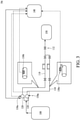
- FIGS. 1 to 3 are schematic drawings of a system for supplying a chemical solution 10a, 10b, 10c according to aspects of one or more embodiments of the present disclosure. It should be understood that same elements in FIGS. 1 to 3 are depicted by same numerals, and repetitive details may be omitted in the interest of brevity.
- the system for supplying the chemical solution 10a, 10b, 10c includes a chemical storage tank 100.
- the chemical storage tank 100 is configured to store one or more types of chemical solutions.
- the system 10a, 10b, 10c may include variable-volume chemical storage tanks 100 (not shown).
- the system 10a, 10b, 10c may further include a mixer configured to mix the chemical solutions stored in the chemical storage tank 100.
- the system 10a, 10b, 10c includes at least a pipeline 110 connected to the chemical storage tank 100 and a pump 120 connected to the pipeline 110.
- the chemical solutions may be mixed by the aforementioned mixer before being supplied to the pipeline 110.
- the system 10a, 10b, 10c can store the chemical solutions and supply the chemical solutions to the pipeline 110 without mixing.
- the pipeline 110 includes an insulating material.
- the pipeline 110 is made of the insulating material.
- the insulating material is selected from the group consisting essentially of perfluoroalkoxy (PFA), polytetrafluoroethylene (PTFE), non-explosive polyfluoroalkoxy (NE-PFA), and anti-static polyfluoroalkoxy (AS-PFA).
- PFA perfluoroalkoxy
- PTFE polytetrafluoroethylene
- NE-PFA non-explosive polyfluoroalkoxy
- AS-PFA anti-static polyfluoroalkoxy
- at least an inner surface of the pipeline 110 includes the insulating material.
- a liner can be formed to entirely cover the inner surface of the pipeline 110.
- the liner can include, for example but not limited thereto, PTFE or high density polyethylene (HDPE).
- the system 10a, 10b, 10c may include other components.
- the components can include a filter (not shown) and a valve 112.
- the valve 112 helps to control the flow of the chemical solutions.
- the valve 112 helps to prevent backflow.
- the valve 112 can be a suck-back valve.
- the valve 112 can be a check valve.
- the valve 112 includes a mechanism for releasing gas trapped in the pipeline 110.
- the valve 112 is an electronically controlled valve.
- the valve 112 is electrically connected to a control unit 140 and is operated by the control unit 140.
- FIG. 4 is a schematic drawing of a portion of the pump 120 according to aspects of one or more embodiments of the present disclosure.
- the pump 120 is connected to the pipeline 110 and is configured to pump the chemical solution from the chemical storage tank 100 into the pipeline 110.
- the pump 120 includes a pump body 121, a right head 112R, a left head 122L, an assembly bellow 123, a shaft 124, a shaft seal 124S, a check seat 125, a check cage 126, a check ball 127 and a check plug 128.
- the pump 120 can include polytetrafluoroethylene (PTFE), which reduces extractable metal ionic contamination.
- the check ball 127 can be a moving element in the pump 120. It should be understood that triboelectricity is generated by a moving element, and thus the check ball 127 is likely to trigger the electrostatic discharge.
- the system 10a, 10b, 10c further includes an electrostatic probe 130a coupled to the pump 120 and configured to measure an electrostatic voltage of the pump 120.
- the electrostatic probe 130a is adopted in proximity to the moving element, such as the check ball 127.
- the electrostatic probe 130a can be coupled to the pump 120 in proximity to the check ball 127, as shown in FIG. 4 .
- a highest electrostatic voltage can be accurately and promptly measured.
- FIG. 5 is a schematic drawing of an electrostatic probe according to aspects of one or more embodiments of the present disclosure.
- the electrostatic probe 130a can be integrated with the check plug 128.
- the electrostatic probe 130a can be enclosed by the check plug 128.
- the electrostatic probe 130a can include an insulative sealing portion 132 and a conductive portion 134 enclosed by the insulative sealing portion 132.
- the insulative sealing portion 132 can include insulating material such as PFA, PTFE, NE-PFA, and AS-PFA, but the disclosure is not limited thereto.
- a width of the conductive portion 134 is less than a width of the check plug 128 or less than a width of the insulative sealing portion 132, such that sidewalls of the conductive portion 134 can be protected by the check plug 128 or protected by the insulative sealing portion 132.
- a length of the insulative sealing portion 132 and a length of the conductive portion 134 can have a ratio, and the ratio can be adjusted according to a liquid flow rate of the chemical solution in the pump 120.
- an end 136-1 of the conductive portion 134 of the electrostatic probe 130a can be exposed through the check plug 128 or exposed through the insulative sealing portion 132 in order to contact the chemical solution in the pump 120 and to measure the electrostatic voltage of the pump 120.
- Another end 136-2 of the conductive portion 134 of the electrostatic probe 130a can be electrically connected to a pre-amplifier 138.
- the pre-amplifier 138 is an electronic amplifier that converts a weak electrical signal into an output signal that is strong enough for further processing.
- an explosion-proof connector and an explosion-proof cable can be used to electrically connect the end 136-2 of the conductive portion 134 of the electrostatic probe 130a to the amplifier 138, but the disclosure is not limited thereto.
- the system 10a, 10b, 10c further includes the control unit 140 coupled to the electrostatic probe 130a, wherein the control unit is configured to obtain an electrostatic voltage from the electrostatic probe 130a.
- the control unit 140 is electrically connected to the pump 120 and configured to adjust at least a parameter of the pump 120.
- the control unit 140 receives signals (i.e., signals indicating the electrostatic voltage of the pump) from the electrostatic probe 130a and sends signals to adjust the parameter of the pump 120 according to the obtained electrostatic voltage.
- the parameters of the pump 120 can include a fluid horsepower, a pump operation speed and a frequency.
- the control unit 140 may send signals to reduce the fluid horsepower, the pump operation speed and/or the frequency. In some embodiments, when the electrostatic voltage of the pump 120 is greater than, for example but not limited to, approximately 5 KV -10 KV, the control unit 140 may send signals to reduce the fluid horsepower, the pump operation speed and/or the frequency. In some comparative approaches, if the control unit 140 sends signals when the electrostatic voltage of the pump 120 is less than approximately 5 KV, the system 10a is so sensitive that false alarm may be triggered. In other comparative approaches, if the control unit 140 sends signals when the electrostatic voltage of the pump 120 is greater than approximately 10 KV, the risk of static electricity may not be detected in time.
- the system 10b includes an electrostatic probe 130a and an electrostatic probe 130b. Both of the electrostatic probe 130a and the electrostatic probe 130b are coupled to the control unit 140.
- the electrostatic probe 130a is coupled to the pump 120 while the electrostatic probe 130b is coupled to an inside of the pipeline 110.
- the electrostatic probe 130a is configured to measure an electrostatic voltage of the pump 120 and provide such measurement to the control unit 140.
- the electrostatic probe 130b is configured to measure an electrostatic voltage of the inside of the pipeline 110 and provide such measurement to the control unit 140.
- the electrostatic probe 130b is attached to an inner surface of the pipeline 110 and is used to measure and monitor the electrostatic voltage of the inside of the pipeline 110 as the chemical solution passes through.
- the electrostatic probe 130b can be attached to the inner surface of the pipeline 110 by an adhesive layer (not shown), but the disclosure is not limited thereto.
- a pre-amplifier (not shown) can be disposed between and electrically connected to the electrostatic probe 130b and the control unit 140, such that a weak electrical signal can be amplified into an output signal that is strong enough for further processing.
- the electrostatic probe 130b can include the insulating sealing portion 132 and the conductive portion 134 as shown in FIG. 5 . Therefore those details are omitted herein for brevity.
- the system 10c includes an electrostatic probe 130a, an electrostatic probe 130b and an electrostatic probe 130c.
- Each of the electrostatic probe 130a, the electrostatic probe 130b and the electrostatic probe 130c is coupled to the control unit 140.
- the electrostatic probe 130a is coupled to the pump 120
- the electrostatic probe 130b is coupled to an inside of the pipeline 110
- the electrostatic probe 130c is coupled to an outside of the pipeline 110.
- the electrostatic probe 130a is configured to measure an electrostatic voltage of the pump 120 and provide such measurement to the control unit 140
- the electrostatic probe 130b is configured to measure an electrostatic voltage of the inside of the pipeline 110 and provide such measurement to the control unit 140
- the electrostatic probe 130c is configured to measure an electrostatic voltage of the outside of the pipeline 110 and provide such measurement to the control unit 140.
- the electrostatic probe 130c is disposed over an outer surface of the pipeline 110 and is used to measure and monitor the electrostatic voltage of the outside of the pipeline 110.
- the electrostatic probe 130b can be attached to the inner surface of the pipeline 110 by an adhesive layer (not shown), but the disclosure is not limited thereto.
- a distance H can be defined between the electrostatic probe 130c and the outer surface of the pipeline 110.
- the distance H can be between approximately 5 mm and approximately 10 mm In some comparative approaches, it is found that when the distance H is less than approximately 5 mm or greater than approximately 10 mm, the measurement is adversely impacted.
- a pre-amplifier (not shown) can be disposed between and electrically connected to the electrostatic probe 130c and the control unit 140, such that a weak electrical signal can be amplified into an output signal that is strong enough for further processing.
- FIG. 6 is a flowchart representing a method for supplying a chemical solution 20 according to aspects of one or more embodiments of the present disclosure.
- the method for supplying the chemical solution 20 includes a number of operations (201, 202, 203, 204, 205 and 206).
- the method for supplying the chemical solution 20 will be further described according to one or more embodiments. It should be noted that the operations of the method for supplying the chemical solution 20 may be rearranged or otherwise modified within the scope of the various aspects. It should further be noted that additional processes may be provided before, during, and after the method for supplying the chemical solution 20, and that some other processes may be only briefly described herein. Thus other implementations are possible within the scope of the various aspects described herein.
- the method for supplying the chemical solution 20 can begin with operation 201 in which a chemical supply system coupled to a processing tool is provided.
- the method 20 proceeds with operation 202 in which at least an electrostatic probe is provided to a pump of the chemical supply system.
- the method 20 proceeds with operation 203 in which a chemical solution is provided to the processing tool via a pipeline by the pump.
- the method 20 proceeds with operation 204 in which an electrostatic voltage of the pump is measured by the electrostatic probe and such measurement is provide to a control unit.
- the method 20 continues with operation 205 in which a parameter of the pump us adjusted by the control unit according to the electrostatic voltage of the pump.
- a chemical supply system is provided and coupled to a processing tool.
- the chemical supply system can include the system for supplying the chemical solution 10a, 10b, 10c.
- the system for supplying the chemical solution 10a, 10b, 10c is coupled to the processing tool 150, as shown in FIGS. 1 to 3 .
- the processing tool 150 includes an etcher, a wet cleaner, and a photolithography system.
- a dispensing device for dispensing chemical solutions onto a surface of a wafer can be disposed between and coupled to the system for supplying the chemical solution 10a, 10b, 10c and the processing tool 150.
- the dispensing device can be used in the photolithography system.
- the chemical solution is suitable for spin coating on the surface of the wafer.
- the chemical solutions can include a bottom anti-reflective coating (BARC) solution or a primer solution such as a primer that improves adhesion between the surface of the wafer and a photoresist.
- the chemical solutions can include photoresist.
- the chemical solutions can include a photoresist developer such as an n-butyl acetate (nBA) (conductivity: 4300 ps/m).
- nBA n-butyl acetate
- the chemical solution includes organic solutions with low conductivity commonly used in semiconductor processes.
- the chemical solutions can include propylene glycol methyl ether acetate (PGMEA) (conductivity: 3*10 4 ps/m), methylpyrrolidone (nMP) (conductivity: 2*10 6 ps/m), etc.
- PGMEA propylene glycol methyl ether acetate
- nMP methylpyrrolidone
- an electrostatic probe 130a is coupled to the pump 120 of the system 10a, as shown in FIG. 1 .
- an electrostatic probe 130a is coupled to the pump 120 and an electrostatic probe 130b is coupled to an inside of the pipeline 110 of the system 10b, as shown in FIG. 2 .
- an electrostatic probe 130a is coupled to the pump 120, an electrostatic probe 130b is coupled to an inside of the pipeline 110, and an electrostatic probe 130c is coupled to an outside of the pipeline 110 of the system 10c, as shown in FIG. 3 .
- FIG. 1 As shown in FIG. 1 , an electrostatic probe 130a is coupled to the pump 120 and an electrostatic probe 130b is coupled to an inside of the pipeline 110 of the system 10b, as shown in FIG. 2 .
- an electrostatic probe 130a is coupled to the pump 120, an electrostatic probe 130b is coupled to an inside of the pipeline 110, and an electrostatic probe 130c is coupled to an outside of the pipeline 110 of the system 10c, as shown in FIG. 3 .
- the electrostatic probe 130a is coupled or adopted in proximity to a moving element such as a check ball 127 of the pump 120.
- the electrostatic probe 130a can be integrated with a check plug 128 which is in proximity to the check ball 127 of the pump 120.
- the chemical solution is provided to the processing tool 150 via the pipeline 110 by the pump 120.
- the chemical solution is pumped from the chemical storage tank 100 into the pipeline 110 by the pump 120, as shown in FIGS. 1 to 3 .
- an electrostatic voltage of the pump 120 is measured by the electrostatic probe 130a, and such measurement is provided to the control unit 140 during the pumping of the chemical solution.
- the electrostatic probe 130a which is in proximity to the check ball 127, can measure a highest electrostatic voltage accurately and promptly.
- the measurement of the electrostatic voltage of the pump 120 can be concurrently provided to the control unit 140, as shown in FIG. 1 .
- the electrostatic probe 130b is also used to measure an electrostatic voltage of the inside of the pipeline 110. Further, the measurement of the electrostatic voltage of the inside of the pipeline 110 is provided to the control unit 140 by the electrostatic probe 130b during the pumping of the chemical solution. In such embodiments, the measurement of the electrostatic voltage of the pump 120 and the measurement of the electrostatic voltage of the inside of the pipeline 110 can be concurrently provided to the control unit 140, as shown in FIG. 2 .
- weighting values can be provided after receiving the measurement of the electrostatic voltage of the pump 120 and receiving the measurement of the electrostatic voltage of the inside of the pipeline 110 in the control unit 140.
- the weighting values may amplify the effects to the pump 120 or the inside of the pipeline 110, depending on the process monitoring requirement. In other embodiments, the weighting values may reduce the effects or noise to the pump 120 or the inside of the pipeline 110, depending on the process monitoring requirement.
- the electrostatic probe 130c is also used to measure an electrostatic voltage of the outside of the pipeline 110 at operation 204. Further, the measurement of the electrostatic voltage of the outside of the pipeline 110 is provided to the control unit 140 by the electrostatic probe 130c during the pumping of the chemical solution. In such embodiments, the measurement of the electrostatic voltage of the pump 120, the measurement of the electrostatic voltage of the inside of the pipeline 110, and the measurement of electrostatic voltage of the outside of the pipeline 110 are concurrently provided to the control unit 140, as shown in FIG. 3 .
- weighting values can be provided after receiving the measurement of the electrostatic voltage of the pump 120, the electrostatic voltage of the measurement of the inside of the pipeline 110 and the measurement of the electrostatic voltage of the outside of the pipeline 110 in the control unit 140.
- the weighting values may amplify the effects to the pump 120, the inside of the pipeline 110 or the outside of the pipeline 140, depending on the process monitoring requirement.
- the weighting values may reduce the effects or noise to the pump 120, the inside of the pipeline 110 or the outside of the pipeline 110, depending on the process monitoring requirement.
- a parameter of the pump 120 is adjusted by the control unit 140.
- the parameter of the pump 120 is adjusted by the control unit 140 according to the measurement of the electrostatic voltage of the pump 120 obtained from the electrostatic probe 130a of the system 10a.
- the parameters of the pump 120 include a fluid horsepower, a pump operation speed and a frequency.
- the control unit 140 may send signals to reduce the fluid horsepower, the pump operation speed and/or the frequency of the pump 120.
- the control unit 140 may send signals to reduce the fluid horsepower, the pump operation speed and/or the frequency of the pump 120.
- the parameters of the pump 120 can be adjusted or tuned by the control unit 140 according to the measurement of the electrostatic voltage of the pump 120 obtained from the electrostatic probe 130a and the measurement of the electrostatic voltage of the inside of the pipeline 110 obtained from the electrostatic probe 130b of the system 10b at operation 205, as shown in FIG. 2 .
- the parameters of the pump 120 can be adjusted or tuned by the control unit 140 according to the measurement of the electrostatic voltage of the pump 120 obtained from the electrostatic probe 130a, measurement of the electrostatic voltage of the inside of the pipeline 110 obtained from the electrostatic probe 130b and the measurement of the electrostatic voltage of the outside of the pipeline 110 obtained from the electrostatic probe 130c of the system 10c.
- the static electricity generated during the pumping of the chemical solution can be reduced. Because the static electricity in the pump is reduced, particle issue can be mitigated.
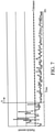
- FIG. 7 is a graph illustrating a relation between particles and time.
- the electrostatic discharge may create particles and the particles may fall on the wafer to be processed and thus the particle contamination is found.
- an upper limit for particle amount found on a wafer can be referred to as a tolerance. When the particle amount found on the wafer is greater than the tolerance, particle contamination is determined to occur. As shown in FIG. 7 , before time A, the wafer may suffer from the particle contamination.
- the control unit 140 may adjust or tune the parameter of the pump 120, such that the static electricity in the pump 120 can be reduced. As shown in FIG. 7 , in some embodiments, the control unit 140 may receive the measurement of the electrostatic voltage of the pump 120 from the electrostatic probe 130a and reduce the fluid horsepower, the pump operation speed and/or the frequency of the pump 120 at time A. Consequently, the static electricity in the pump 120 is reduced, and particle amount is reduced after time A, as shown in FIG. 7 .
- the electrostatic probe 130a is coupled to the pump 120, the static electricity generated in the pump 120 can be continuously monitored and thus the adjustment of the pump 120 can be performed promptly.
- a spark from the outside of the pipeline 110 may ignite a flammable liquid in the solvent-laden environment and cause a fire or explosion in the semiconductor fabrication facility. It is also known that there are two causes of the fire or explosion: a flammable chemical leak caused by the electrostatic discharge through the wall of the pipeline 110 and an electrostatic discharge from the outside of the pipeline 110.
- the electrostatic probe 130b coupled to the inside of the pipeline 110 monitors the electrostatic voltage in the pipeline 110.
- the particle issue can be further mitigated.
- a leak path in the pipeline 110 can be mitigated. It is known that the static electricity generated within the pipeline 110 may cause the leak path. Therefore, because the electrostatic probe 130b measures the electrostatic voltage of the inside of the pipeline 110 and provides such measurement to the control unit 140, the condition of the inside of the pipeline 110 can be monitored, and thus the leak path issue can be mitigated. Further, the risk of the fire due to the leak path caused by the electrostatic discharge through the wall of the pipeline 110 can be reduced.
- the electrostatic probe 130c coupled to the outside of the pipeline 110 monitors the electrostatic voltage of the outer surface of the pipeline 110.
- the control unit 140 may adjust or tune the parameter of the pump 120 such that the static electricity in the pump 120 can be reduced.
- the control unit 140 may send an alarm. Because the electrostatic probe 130c measures the electrostatic voltage of the outside of the pipeline 110 and provides the measurement of the electrostatic voltage to the control unit 140, the condition of the outside of the pipeline 110 can be monitored. Further, the risk of the fire due to the electrostatic discharge from the outside of the pipeline 110 can be reduced.
- the present disclosure therefore provides a system and a method for supplying a chemical solution.
- the system and the method for supplying the chemical solution are used to measure and control static electricity.
- the system includes electrostatic probes coupled to or adopted on pumps and pipelines to provide on line measurement and monitoring.
- the electrostatic probes adopted on the pumps and the pipelines provide continuous static electricity measurement, and therefore external environmental effects or human error can be mitigated.
- the method further adjusts or tunes parameters of the system for supplying the chemical solution to reduce static electricity generation according to the measurement obtained from the electrostatic probes. Accordingly, the adjustment can be performed promptly and thus particle contamination can be mitigated.
- a system for supplying a chemical solution includes a chemical storage tank, a pipeline, a pump, a first electrostatic probe, and a control unit.
- the pipeline is connected to the chemical storage tank
- the pump is connected to the pipeline and configured to pump a chemical solution from the chemical storage tank into the pipeline.
- the first electrostatic probe is coupled to the pump and configured to measure an electrostatic voltage of the pump.
- the control unit is coupled to the first electrostatic probe and configured to obtain a measurement of the electrostatic voltage from the first electrostatic probe.
- the pump includes at least a moving element, and the first electrostatic probe is adopted in proximity to the moving element.
- the moving element includes a check ball.
- the system further includes a second electrostatic probe coupled to the control unit and an inside of the pipeline. The second electrostatic probe is configured to measure an electrostatic voltage of the inside of the pipeline and provide such measurement to the control unit.
- the system further includes a third electrostatic probe coupled to the control unit and an outside of the pipeline. The third electrostatic probe is configured to measure an electrostatic voltage of the outside of the pipeline and provide such measurement to the control unit.
- the control unit is configured to adjust at least a parameter of the pump.
- the parameters include a fluid horsepower, a pump operation speed, and a frequency.
- the pipeline includes an insulating material.
- insulating material is selected from PFA, PTFE, NE-PFA, and AS-PFA.
- a method for supplying a chemical solution includes following operations.
- a first electrostatic probe is provided to a chemical supply system.
- the chemical supply system includes a chemical storage tank, a pipeline, a pump connected to the chemical storage tank and the pipeline, a first electrostatic probe coupled to the pump, and a control unit coupled to the first electrostatic probe.
- a chemical solution is pumped from the chemical storage tank into the pipeline by the pump.
- An electrostatic voltage of the pump is measured by the first electrostatic probe during the pumping of the chemical solution, and such measurement is provided to the control unit.
- a parameter of the pump is adjusted by the control unit according to the measurement of the electrostatic voltage of the pump.
- the adjusting of the parameter of the pump is performed when the electrostatic voltage of the pump is greater than 5 KV.
- the parameters include a fluid horsepower, a pump operation speed, and a frequency.
- the method further includes following operations.
- a second electrostatic probe is provided to an inside of the pipeline.
- An electrostatic voltage of the inside of the pipeline is measured by the second electrostatic probe during the pumping of the chemical solution, and such measurement is provided to the control unit.
- the parameter of the pump is adjusted by the control unit according to the measurement of the electrostatic voltage of the pump and the measurement of the electrostatic voltage of the inside of the pipeline.
- the method further includes following operations.
- a third electrostatic probe is provided to an outside of the pipeline.
- An electrostatic voltage of the outside of the pipeline is measured by the third electrostatic probe during the pumping of the chemical solution, and such measurement is provided to the control unit.
- the parameter of the pump is adjusted by the control unit according to the measurements of the electrostatic voltage of the pump, the electrostatic voltage of the inside of the pipeline, and the electrostatic voltage of the outside of the pipeline.
- a method for supplying a chemical solution includes following operations.
- a chemical supply system coupled to a processing tool is provided.
- the chemical supply system includes a pipeline, a pump connected to the pipeline, and a control unit.
- a first electrostatic probe is provided to the pump.
- a chemical solution is provided to the processing tool via the pipeline by the pump.
- An electrostatic voltage of the pump is measured by the first electrostatic probe during the providing of the chemical solution to the processing tool, and such measurement is provided to the control unit.
- a parameter of the pump is adjusted by the control unit according to the measurement of the electrostatic voltage of the pump.
- the adjusting of the parameter of the pump is performed when the electrostatic voltage of the pump is greater than approximately 5 KV.
- the parameters include a fluid horsepower, a pump operation speed and a frequency.
- the processing tool includes an etcher, a wet cleaner, and a photolithography system.
- the method further includes following operations.
- a second electrostatic probe is provided to an inside of the pipeline.
- An electrostatic voltage of the inside of the pipeline is measured by the second electrostatic probe during the providing of the chemical solution to the processing tool, and such measurement is provided to the control unit.
- the parameter of the pump is adjusted by the control unit according to the measurements of the electrostatic voltage of the pump and the electrostatic voltage of the inside of the pipeline.
- the method further includes following operations.
- a third electrostatic probe is provided to an outside of the pipeline.
- An electrostatic voltage of the outside of the pipeline is measured by the third electrostatic probe during the providing of the chemical solution to the processing tool, and such measurement is provided to the control unit.
- the parameter of the pump is adjusted by the control unit according to the measurements of the electrostatic voltage of the pump, the electrostatic voltage of the inside of the pipeline and the electrostatic voltage of the outside of the pipeline.
Landscapes
- Engineering & Computer Science (AREA)
- Mechanical Engineering (AREA)
- General Engineering & Computer Science (AREA)
- Physics & Mathematics (AREA)
- General Physics & Mathematics (AREA)
- Public Health (AREA)
- Health & Medical Sciences (AREA)
- Water Supply & Treatment (AREA)
- Feeding, Discharge, Calcimining, Fusing, And Gas-Generation Devices (AREA)
- Investigating Or Analyzing Materials By The Use Of Electric Means (AREA)
- Elimination Of Static Electricity (AREA)
- Cleaning Or Drying Semiconductors (AREA)
- Application Of Or Painting With Fluid Materials (AREA)
- Automation & Control Theory (AREA)
Abstract
A system includes a chemical storage tank 100, a pipeline 110, a pump 120, a first electrostatic probe 130a, and a control unit 140. The pipeline is connected to the chemical storage tank The pump is connected to the pipeline and configured to pump a chemical solution from the chemical storage tank into the pipeline. The first electrostatic probe is coupled to the pump and configured to measure an electrostatic voltage of the pump. The control unit is coupled to the first electrostatic probe and configured to obtain a measurement of an electrostatic voltage from the first electrostatic probe.
Description
- In a semiconductor fabrication facility, static electricity leading to electrostatic discharge (ESD) frequently develops on surfaces of articles made of insulating materials when the articles are touched or rubbed by other insulating materials. The buildup of static electricity is often generated by a phenomenon known as a tribocharging theory. The discharge of the static electricity to machines and to human operators can cause damage to semiconductor wafers and process tools, or cause injury to a machine operator. In a semiconductor fabrication facility, it is therefore necessary to control ESD by grounding the machines, by controlling the relative humidity, or by building walls and floor coverings with slightly conductive materials such that electrical charges can be routed to ground. When the triboelectricity is suitably controlled, the control of dust and particulate contamination is also enhanced.
- Aspects of the present disclosure are best understood from the following detailed description when read with the accompanying figures. It should be noted that, in accordance with the standard practice in the industry, various features are not drawn to scale. In fact, the dimensions of the various features may be arbitrarily increased or reduced for clarity of discussion.
-
FIG. 1 is a schematic drawing of a system for supplying a chemical solution according to aspects of one or more embodiments of the present disclosure. -
FIG. 2 is a schematic drawing of a system for supplying a chemical solution according to aspects of one or more embodiments of the present disclosure. -
FIG. 3 is a schematic drawing of a system for supplying a chemical solution according to aspects of one or more embodiments of the present disclosure. -
FIG. 4 is a schematic drawing of a portion of a pump according to aspects of one or more embodiments of the present disclosure. -
FIG. 5 is a schematic drawing of an electrostatic probe according to aspects of one or more embodiments of the present disclosure. -
FIG. 6 is a flowchart representing a method for supplying a chemical solution according to aspects of one or more embodiments of the present disclosure. -
FIG. 7 is a graph illustrating a relation between particles and time. - The following disclosure provides many different embodiments, or examples, for implementing different features of the provided subject matter. Specific examples of elements and arrangements are described below to simplify the present disclosure. These are, of course, merely examples and are not intended to be limiting. For example, the formation of a first feature over or on a second feature in the description that follows may include embodiments in which the first and second features are formed in direct contact, and may also include embodiments in which additional features may be formed between the first and second features, such that the first and second features may not be in direct contact. In addition, the present disclosure may repeat reference numerals and/or letters in the various examples. This repetition is for the purpose of simplicity and clarity and does not in itself dictate a relationship between the various embodiments and/or configurations discussed.
- Further, spatially relative terms, such as "beneath," "below," "lower," "above," "upper," "on" and the like, may be used herein for ease of description to describe one element or feature's relationship to another element(s) or feature(s) as illustrated in the figures. The spatially relative terms are intended to encompass different orientations of the device in use or operation in addition to the orientation depicted in the figures. The device may be otherwise oriented (rotated 100 degrees or at other orientations) and the spatially relative descriptors used herein may likewise be interpreted accordingly.
- As used herein, the terms such as "first," "second" and "third" describe various elements, components, regions, layers and/or sections, but these elements, components, regions, layers and/or sections should not be limited by these terms. These terms may be only used to distinguish one element, component, region, layer or section from another. The terms such as "first," "second" and "third" when used herein do not imply a sequence or order unless clearly indicated by the context.
- Semiconductor processes, such as photolithography, wet etching and cleaning, have become more sensitive at advanced process nodes. The liquids, solvents or solutions used in the photolithography, wet etching or cleaning may extract metal particles. The extracted metals from the chemical delivery systems may cause critical wafer defects that adversely impact process yields. In some comparative approaches, to counter this adverse yield impact, manufacturers have replaced metal pipelines with insulating pipelines such as plastic pipelines. This change results in reduced extracted metals in the process chemicals.
- However, another concern with electrostatic discharge (ESD) is raised with the comparative approaches when a low-conductivity or high-resistance chemical solution is transported or delivered. When such chemical solution is transported, it can easily cause charge separation and accumulation at wall boundaries of pumps and pipelines. The overall mechanism of charge separation and accumulation in the pumps and pipelines generates static electricity. Further, the static electricity generated during the transportation may damage the pipelines and the pumps, and create leak paths. In some comparative approaches, instead of metal particles, insulating particles may be generated in the plastic pipelines, causing particle contamination of wafers. In other comparative approaches, when the chemical solution is flammable, the electrostatic discharge may further cause an ignition or explosion, which could cause extensive damage in a semiconductor fabrication facility.
- The present disclosure therefore provides a system and a method for supplying a chemical solution. The system and the method for supplying the chemical solution are used to measure, monitor and control static electricity. In some embodiments, the system includes electrostatic probes coupled to or adopted on pumps and pipelines to perform on line measurement and monitoring. In some embodiments, the electrostatic probes adopted on the pumps and the pipelines provide continuous static electricity measurement, which can mitigate external environmental effects or human error. In some embodiments, the method further adjusts or tunes parameters of the system for supplying the chemical solution to reduce static electricity generation according to the measurement obtained from the electrostatic probes. Accordingly, the adjustment can be performed promptly and thus particle contamination can be mitigated.
-
FIGS. 1 to 3 are schematic drawings of a system for supplying achemical solution FIGS. 1 to 3 are depicted by same numerals, and repetitive details may be omitted in the interest of brevity. The system for supplying thechemical solution chemical storage tank 100. Thechemical storage tank 100 is configured to store one or more types of chemical solutions. In other embodiments, thesystem system chemical storage tank 100. - The
system pipeline 110 connected to thechemical storage tank 100 and apump 120 connected to thepipeline 110. Depending on the chemical solutions to be supplied by thesystem pipeline 110. In some alternative embodiments, thesystem pipeline 110 without mixing. - In some embodiments, the
pipeline 110 includes an insulating material. In some embodiments, thepipeline 110 is made of the insulating material. In some embodiments, the insulating material is selected from the group consisting essentially of perfluoroalkoxy (PFA), polytetrafluoroethylene (PTFE), non-explosive polyfluoroalkoxy (NE-PFA), and anti-static polyfluoroalkoxy (AS-PFA). In other embodiments, at least an inner surface of thepipeline 110 includes the insulating material. For example, a liner can be formed to entirely cover the inner surface of thepipeline 110. In some embodiments, the liner can include, for example but not limited thereto, PTFE or high density polyethylene (HDPE). - In some embodiments, the
system valve 112. Thevalve 112 helps to control the flow of the chemical solutions. For example, thevalve 112 helps to prevent backflow. In some embodiments, thevalve 112 can be a suck-back valve. In some embodiments, thevalve 112 can be a check valve. In some embodiments, thevalve 112 includes a mechanism for releasing gas trapped in thepipeline 110. In some embodiments, thevalve 112 is an electronically controlled valve. In some embodiments, thevalve 112 is electrically connected to acontrol unit 140 and is operated by thecontrol unit 140. - Please refer to
FIG. 4 , which is a schematic drawing of a portion of thepump 120 according to aspects of one or more embodiments of the present disclosure. Thepump 120 is connected to thepipeline 110 and is configured to pump the chemical solution from thechemical storage tank 100 into thepipeline 110. In some embodiments, thepump 120 includes apump body 121, a right head 112R, aleft head 122L, anassembly bellow 123, ashaft 124, ashaft seal 124S, acheck seat 125, acheck cage 126, acheck ball 127 and acheck plug 128. In some embodiments, thepump 120 can include polytetrafluoroethylene (PTFE), which reduces extractable metal ionic contamination. Thecheck ball 127 can be a moving element in thepump 120. It should be understood that triboelectricity is generated by a moving element, and thus thecheck ball 127 is likely to trigger the electrostatic discharge. - The
system electrostatic probe 130a coupled to thepump 120 and configured to measure an electrostatic voltage of thepump 120. In some embodiments, theelectrostatic probe 130a is adopted in proximity to the moving element, such as thecheck ball 127. As mentioned above, because thecheck ball 127, which is the moving element, is most likely to trigger the electrostatic discharge, theelectrostatic probe 130a can be coupled to thepump 120 in proximity to thecheck ball 127, as shown inFIG. 4 . In some embodiments, because theelectrostatic probe 130a is in proximity to thecheck ball 127, a highest electrostatic voltage can be accurately and promptly measured. - Please refer to
FIG. 5 , which is a schematic drawing of an electrostatic probe according to aspects of one or more embodiments of the present disclosure. In some embodiments, as shown inFIGS. 4 and5 , theelectrostatic probe 130a can be integrated with thecheck plug 128. In such embodiments, theelectrostatic probe 130a can be enclosed by thecheck plug 128. In some embodiments, theelectrostatic probe 130a can include an insulative sealing portion 132 and aconductive portion 134 enclosed by the insulative sealing portion 132. The insulative sealing portion 132 can include insulating material such as PFA, PTFE, NE-PFA, and AS-PFA, but the disclosure is not limited thereto. A width of theconductive portion 134 is less than a width of thecheck plug 128 or less than a width of the insulative sealing portion 132, such that sidewalls of theconductive portion 134 can be protected by thecheck plug 128 or protected by the insulative sealing portion 132. A length of the insulative sealing portion 132 and a length of theconductive portion 134 can have a ratio, and the ratio can be adjusted according to a liquid flow rate of the chemical solution in thepump 120. - Further, an end 136-1 of the
conductive portion 134 of theelectrostatic probe 130a can be exposed through thecheck plug 128 or exposed through the insulative sealing portion 132 in order to contact the chemical solution in thepump 120 and to measure the electrostatic voltage of thepump 120. Another end 136-2 of theconductive portion 134 of theelectrostatic probe 130a can be electrically connected to apre-amplifier 138. Thepre-amplifier 138 is an electronic amplifier that converts a weak electrical signal into an output signal that is strong enough for further processing. In some embodiments, an explosion-proof connector and an explosion-proof cable can be used to electrically connect the end 136-2 of theconductive portion 134 of theelectrostatic probe 130a to theamplifier 138, but the disclosure is not limited thereto. - The
system control unit 140 coupled to theelectrostatic probe 130a, wherein the control unit is configured to obtain an electrostatic voltage from theelectrostatic probe 130a. In some embodiments, thecontrol unit 140 is electrically connected to thepump 120 and configured to adjust at least a parameter of thepump 120. In some embodiments, thecontrol unit 140 receives signals (i.e., signals indicating the electrostatic voltage of the pump) from theelectrostatic probe 130a and sends signals to adjust the parameter of thepump 120 according to the obtained electrostatic voltage. The parameters of thepump 120 can include a fluid horsepower, a pump operation speed and a frequency. In some embodiments, when the electrostatic voltage of thepump 120 is greater than, for example but not limited to, approximately 5 KV, thecontrol unit 140 may send signals to reduce the fluid horsepower, the pump operation speed and/or the frequency. In some embodiments, when the electrostatic voltage of thepump 120 is greater than, for example but not limited to, approximately 5 KV -10 KV, thecontrol unit 140 may send signals to reduce the fluid horsepower, the pump operation speed and/or the frequency. In some comparative approaches, if thecontrol unit 140 sends signals when the electrostatic voltage of thepump 120 is less than approximately 5 KV, thesystem 10a is so sensitive that false alarm may be triggered. In other comparative approaches, if thecontrol unit 140 sends signals when the electrostatic voltage of thepump 120 is greater than approximately 10 KV, the risk of static electricity may not be detected in time. - Referring to
FIG. 2 , in some embodiments, thesystem 10b includes anelectrostatic probe 130a and anelectrostatic probe 130b. Both of theelectrostatic probe 130a and theelectrostatic probe 130b are coupled to thecontrol unit 140. Theelectrostatic probe 130a is coupled to thepump 120 while theelectrostatic probe 130b is coupled to an inside of thepipeline 110. As mentioned above, theelectrostatic probe 130a is configured to measure an electrostatic voltage of thepump 120 and provide such measurement to thecontrol unit 140. Theelectrostatic probe 130b is configured to measure an electrostatic voltage of the inside of thepipeline 110 and provide such measurement to thecontrol unit 140. In some embodiments, theelectrostatic probe 130b is attached to an inner surface of thepipeline 110 and is used to measure and monitor the electrostatic voltage of the inside of thepipeline 110 as the chemical solution passes through. Theelectrostatic probe 130b can be attached to the inner surface of thepipeline 110 by an adhesive layer (not shown), but the disclosure is not limited thereto. In some embodiments, a pre-amplifier (not shown) can be disposed between and electrically connected to theelectrostatic probe 130b and thecontrol unit 140, such that a weak electrical signal can be amplified into an output signal that is strong enough for further processing. In some embodiments, theelectrostatic probe 130b can include the insulating sealing portion 132 and theconductive portion 134 as shown inFIG. 5 . Therefore those details are omitted herein for brevity. - Referring to
FIG. 3 , in some embodiments, thesystem 10c includes anelectrostatic probe 130a, anelectrostatic probe 130b and anelectrostatic probe 130c. Each of theelectrostatic probe 130a, theelectrostatic probe 130b and theelectrostatic probe 130c is coupled to thecontrol unit 140. Theelectrostatic probe 130a is coupled to thepump 120, theelectrostatic probe 130b is coupled to an inside of thepipeline 110, and theelectrostatic probe 130c is coupled to an outside of thepipeline 110. Theelectrostatic probe 130a is configured to measure an electrostatic voltage of thepump 120 and provide such measurement to thecontrol unit 140, theelectrostatic probe 130b is configured to measure an electrostatic voltage of the inside of thepipeline 110 and provide such measurement to thecontrol unit 140, and theelectrostatic probe 130c is configured to measure an electrostatic voltage of the outside of thepipeline 110 and provide such measurement to thecontrol unit 140. In some embodiments, theelectrostatic probe 130c is disposed over an outer surface of thepipeline 110 and is used to measure and monitor the electrostatic voltage of the outside of thepipeline 110. As mentioned above, theelectrostatic probe 130b can be attached to the inner surface of thepipeline 110 by an adhesive layer (not shown), but the disclosure is not limited thereto. A distance H can be defined between theelectrostatic probe 130c and the outer surface of thepipeline 110. In some embodiments, the distance H can be between approximately 5 mm and approximately 10 mm In some comparative approaches, it is found that when the distance H is less than approximately 5 mm or greater than approximately 10 mm, the measurement is adversely impacted. In some embodiments, a pre-amplifier (not shown) can be disposed between and electrically connected to theelectrostatic probe 130c and thecontrol unit 140, such that a weak electrical signal can be amplified into an output signal that is strong enough for further processing. - Please refer to
FIG. 6 , which is a flowchart representing a method for supplying achemical solution 20 according to aspects of one or more embodiments of the present disclosure. The method for supplying thechemical solution 20 includes a number of operations (201, 202, 203, 204, 205 and 206). The method for supplying thechemical solution 20 will be further described according to one or more embodiments. It should be noted that the operations of the method for supplying thechemical solution 20 may be rearranged or otherwise modified within the scope of the various aspects. It should further be noted that additional processes may be provided before, during, and after the method for supplying thechemical solution 20, and that some other processes may be only briefly described herein. Thus other implementations are possible within the scope of the various aspects described herein. - In some embodiments, the method for supplying the
chemical solution 20 can begin withoperation 201 in which a chemical supply system coupled to a processing tool is provided. Themethod 20 proceeds withoperation 202 in which at least an electrostatic probe is provided to a pump of the chemical supply system. Themethod 20 proceeds withoperation 203 in which a chemical solution is provided to the processing tool via a pipeline by the pump. Themethod 20 proceeds withoperation 204 in which an electrostatic voltage of the pump is measured by the electrostatic probe and such measurement is provide to a control unit. Themethod 20 continues withoperation 205 in which a parameter of the pump us adjusted by the control unit according to the electrostatic voltage of the pump. - In some embodiments, at
operation 201, a chemical supply system is provided and coupled to a processing tool. Referring toFIGS. 1 to 3 , the chemical supply system can include the system for supplying thechemical solution chemical solution processing tool 150, as shown inFIGS. 1 to 3 . In some embodiments, theprocessing tool 150 includes an etcher, a wet cleaner, and a photolithography system. In some embodiments, a dispensing device for dispensing chemical solutions onto a surface of a wafer can be disposed between and coupled to the system for supplying thechemical solution processing tool 150. In some embodiments, the dispensing device can be used in the photolithography system. In such embodiments, the chemical solution is suitable for spin coating on the surface of the wafer. For example, the chemical solutions can include a bottom anti-reflective coating (BARC) solution or a primer solution such as a primer that improves adhesion between the surface of the wafer and a photoresist. In some embodiments, the chemical solutions can include photoresist. In some embodiments, the chemical solutions can include a photoresist developer such as an n-butyl acetate (nBA) (conductivity: 4300 ps/m). In other embodiments, the chemical solution includes organic solutions with low conductivity commonly used in semiconductor processes. For example, the chemical solutions can include propylene glycol methyl ether acetate (PGMEA) (conductivity: 3*104 ps/m), methylpyrrolidone (nMP) (conductivity: 2*106 ps/m), etc. - At
operation 202, at least an electrostatic probe is provided and coupled to the system for supplying thechemical solution electrostatic probe 130a is coupled to thepump 120 of thesystem 10a, as shown inFIG. 1 . In some embodiments, anelectrostatic probe 130a is coupled to thepump 120 and anelectrostatic probe 130b is coupled to an inside of thepipeline 110 of thesystem 10b, as shown inFIG. 2 . In other embodiments, anelectrostatic probe 130a is coupled to thepump 120, anelectrostatic probe 130b is coupled to an inside of thepipeline 110, and anelectrostatic probe 130c is coupled to an outside of thepipeline 110 of thesystem 10c, as shown inFIG. 3 . As shown inFIG. 4 , in some embodiments, theelectrostatic probe 130a is coupled or adopted in proximity to a moving element such as acheck ball 127 of thepump 120. In some embodiments, theelectrostatic probe 130a can be integrated with acheck plug 128 which is in proximity to thecheck ball 127 of thepump 120. - At
operation 203, the chemical solution is provided to theprocessing tool 150 via thepipeline 110 by thepump 120. In some embodiments, the chemical solution is pumped from thechemical storage tank 100 into thepipeline 110 by thepump 120, as shown inFIGS. 1 to 3 . - At
operation 204, an electrostatic voltage of thepump 120 is measured by theelectrostatic probe 130a, and such measurement is provided to thecontrol unit 140 during the pumping of the chemical solution. As mentioned above, because thecheck ball 127 is most likely to trigger the electrostatic discharge, theelectrostatic probe 130a, which is in proximity to thecheck ball 127, can measure a highest electrostatic voltage accurately and promptly. In such embodiments, the measurement of the electrostatic voltage of thepump 120 can be concurrently provided to thecontrol unit 140, as shown inFIG. 1 . - In some embodiments, at
operation 204, theelectrostatic probe 130b is also used to measure an electrostatic voltage of the inside of thepipeline 110. Further, the measurement of the electrostatic voltage of the inside of thepipeline 110 is provided to thecontrol unit 140 by theelectrostatic probe 130b during the pumping of the chemical solution. In such embodiments, the measurement of the electrostatic voltage of thepump 120 and the measurement of the electrostatic voltage of the inside of thepipeline 110 can be concurrently provided to thecontrol unit 140, as shown inFIG. 2 . - In some embodiments, weighting values can be provided after receiving the measurement of the electrostatic voltage of the
pump 120 and receiving the measurement of the electrostatic voltage of the inside of thepipeline 110 in thecontrol unit 140. In some embodiments, the weighting values may amplify the effects to thepump 120 or the inside of thepipeline 110, depending on the process monitoring requirement. In other embodiments, the weighting values may reduce the effects or noise to thepump 120 or the inside of thepipeline 110, depending on the process monitoring requirement. - In some embodiments, the
electrostatic probe 130c is also used to measure an electrostatic voltage of the outside of thepipeline 110 atoperation 204. Further, the measurement of the electrostatic voltage of the outside of thepipeline 110 is provided to thecontrol unit 140 by theelectrostatic probe 130c during the pumping of the chemical solution. In such embodiments, the measurement of the electrostatic voltage of thepump 120, the measurement of the electrostatic voltage of the inside of thepipeline 110, and the measurement of electrostatic voltage of the outside of thepipeline 110 are concurrently provided to thecontrol unit 140, as shown inFIG. 3 . - In some embodiments, weighting values can be provided after receiving the measurement of the electrostatic voltage of the
pump 120, the electrostatic voltage of the measurement of the inside of thepipeline 110 and the measurement of the electrostatic voltage of the outside of thepipeline 110 in thecontrol unit 140. In some embodiments, the weighting values may amplify the effects to thepump 120, the inside of thepipeline 110 or the outside of thepipeline 140, depending on the process monitoring requirement. In other embodiments, the weighting values may reduce the effects or noise to thepump 120, the inside of thepipeline 110 or the outside of thepipeline 110, depending on the process monitoring requirement. - At
operation 205, a parameter of thepump 120 is adjusted by thecontrol unit 140. In some embodiments, as shown inFIG. 1 , the parameter of thepump 120 is adjusted by thecontrol unit 140 according to the measurement of the electrostatic voltage of thepump 120 obtained from theelectrostatic probe 130a of thesystem 10a. In some embodiments, the parameters of thepump 120 include a fluid horsepower, a pump operation speed and a frequency. For example, when the electrostatic voltage of thepump 120 is greater than approximately 5 KV, thecontrol unit 140 may send signals to reduce the fluid horsepower, the pump operation speed and/or the frequency of thepump 120. For example, when the electrostatic voltage of thepump 120 is greater than approximately 5 KV-10 KV, thecontrol unit 140 may send signals to reduce the fluid horsepower, the pump operation speed and/or the frequency of thepump 120. - In some embodiments, the parameters of the
pump 120 can be adjusted or tuned by thecontrol unit 140 according to the measurement of the electrostatic voltage of thepump 120 obtained from theelectrostatic probe 130a and the measurement of the electrostatic voltage of the inside of thepipeline 110 obtained from theelectrostatic probe 130b of thesystem 10b atoperation 205, as shown inFIG. 2 . - In some embodiments, at
operation 205, as shown in inFIG. 3 , the parameters of thepump 120 can be adjusted or tuned by thecontrol unit 140 according to the measurement of the electrostatic voltage of thepump 120 obtained from theelectrostatic probe 130a, measurement of the electrostatic voltage of the inside of thepipeline 110 obtained from theelectrostatic probe 130b and the measurement of the electrostatic voltage of the outside of thepipeline 110 obtained from theelectrostatic probe 130c of thesystem 10c. - In some embodiments, by reducing the parameters of the
pump 120, the static electricity generated during the pumping of the chemical solution can be reduced. Because the static electricity in the pump is reduced, particle issue can be mitigated. Please refer toFIG. 7 , which is a graph illustrating a relation between particles and time. In some embodiments, the electrostatic discharge may create particles and the particles may fall on the wafer to be processed and thus the particle contamination is found. In some embodiments, an upper limit for particle amount found on a wafer can be referred to as a tolerance. When the particle amount found on the wafer is greater than the tolerance, particle contamination is determined to occur. As shown inFIG. 7 , before time A, the wafer may suffer from the particle contamination. Because the particle amount is correlated to the static electricity, when the static electricity is reduced, the particle amount is inherently reduced. To mitigate such particle contamination issue, when thecontrol unit 140 receives measurement of the electrostatic voltage of thepump 120 from theelectrostatic probe 130a, thecontrol unit 140 may adjust or tune the parameter of thepump 120, such that the static electricity in thepump 120 can be reduced. As shown inFIG. 7 , in some embodiments, thecontrol unit 140 may receive the measurement of the electrostatic voltage of thepump 120 from theelectrostatic probe 130a and reduce the fluid horsepower, the pump operation speed and/or the frequency of thepump 120 at time A. Consequently, the static electricity in thepump 120 is reduced, and particle amount is reduced after time A, as shown inFIG. 7 . - Further, because the
electrostatic probe 130a is coupled to thepump 120, the static electricity generated in thepump 120 can be continuously monitored and thus the adjustment of thepump 120 can be performed promptly. - It is known that a spark from the outside of the
pipeline 110 may ignite a flammable liquid in the solvent-laden environment and cause a fire or explosion in the semiconductor fabrication facility. It is also known that there are two causes of the fire or explosion: a flammable chemical leak caused by the electrostatic discharge through the wall of thepipeline 110 and an electrostatic discharge from the outside of thepipeline 110. - In some embodiments, the
electrostatic probe 130b coupled to the inside of thepipeline 110 monitors the electrostatic voltage in thepipeline 110. Thus, the particle issue can be further mitigated. In such embodiments, a leak path in thepipeline 110 can be mitigated. It is known that the static electricity generated within thepipeline 110 may cause the leak path. Therefore, because theelectrostatic probe 130b measures the electrostatic voltage of the inside of thepipeline 110 and provides such measurement to thecontrol unit 140, the condition of the inside of thepipeline 110 can be monitored, and thus the leak path issue can be mitigated. Further, the risk of the fire due to the leak path caused by the electrostatic discharge through the wall of thepipeline 110 can be reduced. - The
electrostatic probe 130c coupled to the outside of thepipeline 110 monitors the electrostatic voltage of the outer surface of thepipeline 110. In such embodiments, when thecontrol unit 140 receives the measurement of the electrostatic voltage of the outside of thepipeline 110 from theelectrostatic probe 130c, thecontrol unit 140 may adjust or tune the parameter of thepump 120 such that the static electricity in thepump 120 can be reduced. In other embodiments, thecontrol unit 140 may send an alarm. Because theelectrostatic probe 130c measures the electrostatic voltage of the outside of thepipeline 110 and provides the measurement of the electrostatic voltage to thecontrol unit 140, the condition of the outside of thepipeline 110 can be monitored. Further, the risk of the fire due to the electrostatic discharge from the outside of thepipeline 110 can be reduced. - The present disclosure therefore provides a system and a method for supplying a chemical solution. The system and the method for supplying the chemical solution are used to measure and control static electricity. In some embodiments, the system includes electrostatic probes coupled to or adopted on pumps and pipelines to provide on line measurement and monitoring. In some embodiments, the electrostatic probes adopted on the pumps and the pipelines provide continuous static electricity measurement, and therefore external environmental effects or human error can be mitigated. In some embodiments, the method further adjusts or tunes parameters of the system for supplying the chemical solution to reduce static electricity generation according to the measurement obtained from the electrostatic probes. Accordingly, the adjustment can be performed promptly and thus particle contamination can be mitigated.
- In some embodiments, a system for supplying a chemical solution is provided. The system includes a chemical storage tank, a pipeline, a pump, a first electrostatic probe, and a control unit. The pipeline is connected to the chemical storage tank The pump is connected to the pipeline and configured to pump a chemical solution from the chemical storage tank into the pipeline. The first electrostatic probe is coupled to the pump and configured to measure an electrostatic voltage of the pump. The control unit is coupled to the first electrostatic probe and configured to obtain a measurement of the electrostatic voltage from the first electrostatic probe.
- In some embodiments, the pump includes at least a moving element, and the first electrostatic probe is adopted in proximity to the moving element. In some embodiments, the moving element includes a check ball. In some embodiments, the system further includes a second electrostatic probe coupled to the control unit and an inside of the pipeline. The second electrostatic probe is configured to measure an electrostatic voltage of the inside of the pipeline and provide such measurement to the control unit. In some embodiments, the system further includes a third electrostatic probe coupled to the control unit and an outside of the pipeline. The third electrostatic probe is configured to measure an electrostatic voltage of the outside of the pipeline and provide such measurement to the control unit. In some embodiments, the control unit is configured to adjust at least a parameter of the pump. In some embodiments, the parameters include a fluid horsepower, a pump operation speed, and a frequency. In some embodiments, the pipeline includes an insulating material. In some embodiments, insulating material is selected from PFA, PTFE, NE-PFA, and AS-PFA.
- In some embodiments, a method for supplying a chemical solution is provided. The method includes following operations. A first electrostatic probe is provided to a chemical supply system. In some embodiments, the chemical supply system includes a chemical storage tank, a pipeline, a pump connected to the chemical storage tank and the pipeline, a first electrostatic probe coupled to the pump, and a control unit coupled to the first electrostatic probe. A chemical solution is pumped from the chemical storage tank into the pipeline by the pump. An electrostatic voltage of the pump is measured by the first electrostatic probe during the pumping of the chemical solution, and such measurement is provided to the control unit. A parameter of the pump is adjusted by the control unit according to the measurement of the electrostatic voltage of the pump.
- In some embodiments, the adjusting of the parameter of the pump is performed when the electrostatic voltage of the pump is greater than 5 KV. In some embodiments, the parameters include a fluid horsepower, a pump operation speed, and a frequency.
- In some embodiments, the method further includes following operations. A second electrostatic probe is provided to an inside of the pipeline. An electrostatic voltage of the inside of the pipeline is measured by the second electrostatic probe during the pumping of the chemical solution, and such measurement is provided to the control unit. The parameter of the pump is adjusted by the control unit according to the measurement of the electrostatic voltage of the pump and the measurement of the electrostatic voltage of the inside of the pipeline.
- In some embodiments, the method further includes following operations. A third electrostatic probe is provided to an outside of the pipeline. An electrostatic voltage of the outside of the pipeline is measured by the third electrostatic probe during the pumping of the chemical solution, and such measurement is provided to the control unit. The parameter of the pump is adjusted by the control unit according to the measurements of the electrostatic voltage of the pump, the electrostatic voltage of the inside of the pipeline, and the electrostatic voltage of the outside of the pipeline.
- In some embodiments, a method for supplying a chemical solution is provided. The method includes following operations. A chemical supply system coupled to a processing tool is provided. The chemical supply system includes a pipeline, a pump connected to the pipeline, and a control unit. A first electrostatic probe is provided to the pump. A chemical solution is provided to the processing tool via the pipeline by the pump. An electrostatic voltage of the pump is measured by the first electrostatic probe during the providing of the chemical solution to the processing tool, and such measurement is provided to the control unit. A parameter of the pump is adjusted by the control unit according to the measurement of the electrostatic voltage of the pump.
- In some embodiments, the adjusting of the parameter of the pump is performed when the electrostatic voltage of the pump is greater than approximately 5 KV. In some embodiments, the parameters include a fluid horsepower, a pump operation speed and a frequency. In some embodiments, the processing tool includes an etcher, a wet cleaner, and a photolithography system.
- In some embodiments, the method further includes following operations. A second electrostatic probe is provided to an inside of the pipeline. An electrostatic voltage of the inside of the pipeline is measured by the second electrostatic probe during the providing of the chemical solution to the processing tool, and such measurement is provided to the control unit. The parameter of the pump is adjusted by the control unit according to the measurements of the electrostatic voltage of the pump and the electrostatic voltage of the inside of the pipeline.
- In some embodiments, the method further includes following operations. A third electrostatic probe is provided to an outside of the pipeline. An electrostatic voltage of the outside of the pipeline is measured by the third electrostatic probe during the providing of the chemical solution to the processing tool, and such measurement is provided to the control unit. The parameter of the pump is adjusted by the control unit according to the measurements of the electrostatic voltage of the pump, the electrostatic voltage of the inside of the pipeline and the electrostatic voltage of the outside of the pipeline.
- The foregoing outlines features of several embodiments so that those skilled in the art may better understand the aspects of the present disclosure. Those skilled in the art should appreciate that they may readily use the present disclosure as a basis for designing or modifying other processes and structures for carrying out the same purposes and/or achieving the same advantages of the embodiments introduced herein. Those skilled in the art should also realize that such equivalent constructions do not depart from the spirit and scope of the present disclosure, and that they may make various changes, substitutions, and alterations herein without departing from the spirit and scope of the present disclosure.
Claims (9)
- A system for supplying chemical solutions, comprising:a chemical storage tank;a pipeline connected to the chemical storage tank;a pump connected to the pipeline and configured to pump a chemical solution from the chemical storage tank into the pipeline;a first electrostatic probe coupled to the pump and configured to measure an electrostatic voltage of the pump; anda control unit coupled to the first electrostatic probe and configured to obtain the measurement of the electrostatic voltage from the first electrostatic probe.
- The system of Claim 1, wherein the pump comprises at least a moving element, and the first electrostatic probe is adopted in proximity to the moving element.
- The system of Claim 2, wherein the moving element comprises a check ball.
- The system of Claim 1, further comprising a second electrostatic probe coupled to the control unit and an inside of the pipeline, and configured to provide a measurement of an electrostatic voltage of the inside of the pipeline to the control unit.
- The system of Claim 1, further comprising a third electrostatic probe coupled to the control unit and an outside of the pipeline, and configured to provide a measurement of an electrostatic voltage of the outside of the pipeline to the control unit.
- The system of Claim 1, wherein the control unit is configured to adjust at least a parameter of the pump.
- The system of Claim 6, wherein the parameters comprise a fluid horsepower, a pump operation speed and a frequency.
- The system of Claim 1, wherein the pipeline comprises an insulating material.
- The system of Claim 8, wherein the insulating material is selected from the group consisting essentially of perfluoroalkoxy (PFA), polytetrafluoroethylene (PTFE), non-explosive polyfluoroalkoxy (NE-PFA), and anti-static polyfluoroalkoxy (AS-PFA).
Applications Claiming Priority (1)
| Application Number | Priority Date | Filing Date | Title |
|---|---|---|---|
| US16/932,649 US11721561B2 (en) | 2020-07-17 | 2020-07-17 | System and method for supplying chemical solution |
Publications (1)
| Publication Number | Publication Date |
|---|---|
| EP3940229A1 true EP3940229A1 (en) | 2022-01-19 |
Family
ID=77338461
Family Applications (1)
| Application Number | Title | Priority Date | Filing Date |
|---|---|---|---|
| EP21186057.2A Withdrawn EP3940229A1 (en) | 2020-07-17 | 2021-07-16 | System and method for supplying chemical solution |
Country Status (5)
| Country | Link |
|---|---|
| US (2) | US11721561B2 (en) |
| EP (1) | EP3940229A1 (en) |
| JP (1) | JP2022019673A (en) |
| CN (1) | CN113701058B (en) |
| TW (1) | TWI782413B (en) |
Citations (3)
| Publication number | Priority date | Publication date | Assignee | Title |
|---|---|---|---|---|
| US4599045A (en) * | 1985-01-16 | 1986-07-08 | Texaco Inc. | Safety means and method for the handling of flammable fluids |
| WO2006121867A2 (en) * | 2005-05-06 | 2006-11-16 | Quasar Federal Systems, Inc. | Electrostatic monitoring system |
| KR20100072817A (en) * | 2008-12-22 | 2010-07-01 | 자동차부품연구원 | Apparatus for measuring static electricity for modularized fuel supply unit |
Family Cites Families (22)
| Publication number | Priority date | Publication date | Assignee | Title |
|---|---|---|---|---|
| JPS5830552B2 (en) * | 1977-12-13 | 1983-06-29 | 三菱電機株式会社 | Static electricity monitoring device for transformers, etc. |
| JPS5815067B2 (en) * | 1977-12-13 | 1983-03-23 | 三菱電機株式会社 | Static electricity monitoring device for transformers, etc. |
| JPH03150474A (en) * | 1989-11-08 | 1991-06-26 | Shishido Seidenki Kk | Inspecting device for static eliminator |
| US5305714A (en) | 1991-07-03 | 1994-04-26 | Nippon Soken, Inc. | Fuel supply system for an internal combustion engine |
| JP2000265945A (en) * | 1998-11-10 | 2000-09-26 | Uct Kk | Chemical liquid supply pump, chemical liquid supply device, chemical liquid supply system, substrate cleaning device, chemical liquid supply method, and substrate cleaning method |
| TWI238812B (en) * | 1999-11-03 | 2005-09-01 | Ciba Sc Holding Ag | Pigmented vitreous material |
| TWI269396B (en) | 2002-02-08 | 2006-12-21 | Winbond Electronics Corp | An evaluative method for the electrostatic damage to the silicon wafer causing by the cleaning process |
| TWI265908B (en) | 2005-03-25 | 2006-11-11 | Yang Hsueh Chang | Safe oil-unloading system free from damage of static electricity |
| KR20130140012A (en) | 2010-10-22 | 2013-12-23 | 라이트람, 엘엘씨 | Conveyor system, belt, and method for measuring and controlling static electricity |
| CN105060234B (en) * | 2015-08-14 | 2018-04-24 | 中国石油化工股份有限公司青岛安全工程研究院 | The dewatering filter core adding set and orientation adding method of orientation addition antistatic agent |
| CN105526135B (en) * | 2015-12-08 | 2018-02-06 | 北京有色金属研究总院 | A kind of reversely low driving voltage bilateral pumping diaphragm valveless mems electrostatic pump and preparation method thereof |
| JP2019513981A (en) | 2016-04-08 | 2019-05-30 | トレック インコーポレイテッド | This application claims priority to US Provisional Patent Application No. 62 / 320,409 filed Apr. 8, 2016, which is an electrostatic force detector excellent in shielding and method of using the electrostatic force detector. It is a thing. |
| CN108097486A (en) * | 2016-11-25 | 2018-06-01 | 李晓兵 | A kind of Electrostatic greasing electrical-mechanical system based on Advanced Control Techniques |
| CN106771317A (en) * | 2017-01-06 | 2017-05-31 | 中国核动力研究设计院 | A kind of reactor coolant pump rotating speed measurement method |
| KR102465540B1 (en) * | 2017-05-18 | 2022-11-11 | 삼성전자주식회사 | Chemical liquid supply apparatus and semiconductor processing apparatus having the same |
| GB2576036A (en) * | 2018-08-02 | 2020-02-05 | Airbus Operations Ltd | Refuelling system |
| CN209513921U (en) * | 2018-09-18 | 2019-10-18 | 国网江苏省电力有限公司盐城供电分公司 | A static electricity intelligent detection and early warning device for electric power equipment |
| KR20200062831A (en) | 2018-11-27 | 2020-06-04 | 삼성전자주식회사 | Chemical Liquid Supply Apparatus and Semiconductor Processing Apparatus Having the Same |
| EP3670921B1 (en) * | 2018-12-21 | 2023-06-07 | Grundfos Holding A/S | Pump assembly and method of controlling a pump |
| CN209539663U (en) * | 2019-01-24 | 2019-10-25 | 洛阳绿潮环保科技有限公司 | A kind of intelligence note control device ensureing boat coal quality |
| US11280823B2 (en) * | 2019-10-25 | 2022-03-22 | Taiwan Semiconductor Manufacturing Company Ltd. | Monitoring system and method of monitoring static charge |
| CN111271840A (en) * | 2020-03-09 | 2020-06-12 | 珠海格力电器股份有限公司 | Effective voltage abnormity protection method and device and air conditioning unit |
-
2020
- 2020-07-17 US US16/932,649 patent/US11721561B2/en active Active
-
2021
- 2021-02-05 TW TW110104465A patent/TWI782413B/en active
- 2021-03-10 CN CN202110259551.XA patent/CN113701058B/en active Active
- 2021-07-16 EP EP21186057.2A patent/EP3940229A1/en not_active Withdrawn
- 2021-07-16 JP JP2021117596A patent/JP2022019673A/en active Pending
-
2023
- 2023-06-21 US US18/338,354 patent/US12146483B2/en active Active
Patent Citations (3)
| Publication number | Priority date | Publication date | Assignee | Title |
|---|---|---|---|---|
| US4599045A (en) * | 1985-01-16 | 1986-07-08 | Texaco Inc. | Safety means and method for the handling of flammable fluids |
| WO2006121867A2 (en) * | 2005-05-06 | 2006-11-16 | Quasar Federal Systems, Inc. | Electrostatic monitoring system |
| KR20100072817A (en) * | 2008-12-22 | 2010-07-01 | 자동차부품연구원 | Apparatus for measuring static electricity for modularized fuel supply unit |
Also Published As
| Publication number | Publication date |
|---|---|
| US12146483B2 (en) | 2024-11-19 |
| TWI782413B (en) | 2022-11-01 |
| US11721561B2 (en) | 2023-08-08 |
| JP2022019673A (en) | 2022-01-27 |
| US20220020608A1 (en) | 2022-01-20 |
| US20230335416A1 (en) | 2023-10-19 |
| CN113701058B (en) | 2024-03-22 |
| CN113701058A (en) | 2021-11-26 |
| TW202205475A (en) | 2022-02-01 |
Similar Documents
| Publication | Publication Date | Title |
|---|---|---|
| US12117106B2 (en) | Fluid circuit with integrated electrostatic discharge mitigation | |
| US8242026B2 (en) | Semiconductor device manufacturing method, semiconductor manufacturing apparatus and storage medium | |
| US20080173327A1 (en) | Two-fluid nozzle, substrate processing apparatus, and substrate processing method | |
| US12055575B2 (en) | Method of monitoring static charge | |
| CN111223792A (en) | Chemical liquid supply device and semiconductor processing device having the same | |
| CN100573819C (en) | Substrate processing apparatus and substrate processing method | |
| US20170023158A1 (en) | Chemical Dispense System with Reduced Contamination | |
| CN111871055A (en) | Filter with ESD Mitigation Sleeve | |
| US12146483B2 (en) | System for supplying chemical solution | |
| US20240304480A1 (en) | Measuring system and method of measuring static charges | |
| KR20250057766A (en) | Substrate processing apparatus and method for determining deterioration degree of conductive pipe | |
| US10809620B1 (en) | Systems and methods for developer drain line monitoring | |
| JP2008251756A (en) | Substrate treating apparatus and method | |
| JP6899228B2 (en) | Board processing equipment | |
| US12500096B2 (en) | Apparatus for inspecting droplet and substrate processing apparatus including the same | |
| KR102905642B1 (en) | electrostatic discharge relief valve | |
| TWI920282B (en) | Measuring system and method of measuring static charges | |
| TWI885237B (en) | Substrate processing apparatus and substrate processing method | |
| CN117299666B (en) | Substrate processing apparatus | |
| KR100481556B1 (en) | Develop water dispense apparatus | |
| JP2023182121A (en) | Cleaning time calculation method | |
| TW202534839A (en) | Substrate processing system and substrate processing method | |
| CN112710905A (en) | Static charge monitoring system and monitoring method thereof | |
| CN117906074A (en) | Wafer cleaning equipment and leakage detection method thereof | |
| CN120883332A (en) | Substrate processing apparatus and substrate processing method |
Legal Events
| Date | Code | Title | Description |
|---|---|---|---|
| PUAI | Public reference made under article 153(3) epc to a published international application that has entered the european phase |
Free format text: ORIGINAL CODE: 0009012 |
|
| STAA | Information on the status of an ep patent application or granted ep patent |
Free format text: STATUS: THE APPLICATION HAS BEEN PUBLISHED |
|
| AK | Designated contracting states |
Kind code of ref document: A1 Designated state(s): AL AT BE BG CH CY CZ DE DK EE ES FI FR GB GR HR HU IE IS IT LI LT LU LV MC MK MT NL NO PL PT RO RS SE SI SK SM TR |
|
| STAA | Information on the status of an ep patent application or granted ep patent |
Free format text: STATUS: THE APPLICATION IS DEEMED TO BE WITHDRAWN |
|
| 18D | Application deemed to be withdrawn |
Effective date: 20220720 |