EP3940158A1 - Armature sanitaire pourvu d'un écrou de montage rapide - Google Patents
Armature sanitaire pourvu d'un écrou de montage rapide Download PDFInfo
- Publication number
- EP3940158A1 EP3940158A1 EP20186244.8A EP20186244A EP3940158A1 EP 3940158 A1 EP3940158 A1 EP 3940158A1 EP 20186244 A EP20186244 A EP 20186244A EP 3940158 A1 EP3940158 A1 EP 3940158A1
- Authority
- EP
- European Patent Office
- Prior art keywords
- nut
- threaded rod
- counter
- retaining element
- sanitary fitting
- Prior art date
- Legal status (The legal status is an assumption and is not a legal conclusion. Google has not performed a legal analysis and makes no representation as to the accuracy of the status listed.)
- Withdrawn
Links
- 230000009467 reduction Effects 0.000 claims description 35
- 230000000295 complement effect Effects 0.000 claims description 3
- 238000007789 sealing Methods 0.000 claims description 2
- 238000000034 method Methods 0.000 description 3
- 230000008569 process Effects 0.000 description 3
- 238000011161 development Methods 0.000 description 2
- 230000018109 developmental process Effects 0.000 description 2
- 238000009434 installation Methods 0.000 description 2
- 241001295925 Gegenes Species 0.000 description 1
- 230000004323 axial length Effects 0.000 description 1
- 230000008901 benefit Effects 0.000 description 1
- 230000003247 decreasing effect Effects 0.000 description 1
- 230000001419 dependent effect Effects 0.000 description 1
- 230000003993 interaction Effects 0.000 description 1
- 210000003734 kidney Anatomy 0.000 description 1
- 239000007788 liquid Substances 0.000 description 1
- 239000000463 material Substances 0.000 description 1
- 238000003032 molecular docking Methods 0.000 description 1
- 230000000284 resting effect Effects 0.000 description 1
Images


Classifications
-
- E—FIXED CONSTRUCTIONS
- E03—WATER SUPPLY; SEWERAGE
- E03C—DOMESTIC PLUMBING INSTALLATIONS FOR FRESH WATER OR WASTE WATER; SINKS
- E03C1/00—Domestic plumbing installations for fresh water or waste water; Sinks
- E03C1/02—Plumbing installations for fresh water
- E03C1/04—Water-basin installations specially adapted to wash-basins or baths
- E03C1/0401—Fixing a tap to the sanitary appliance or to an associated mounting surface, e.g. a countertop
-
- F—MECHANICAL ENGINEERING; LIGHTING; HEATING; WEAPONS; BLASTING
- F16—ENGINEERING ELEMENTS AND UNITS; GENERAL MEASURES FOR PRODUCING AND MAINTAINING EFFECTIVE FUNCTIONING OF MACHINES OR INSTALLATIONS; THERMAL INSULATION IN GENERAL
- F16B—DEVICES FOR FASTENING OR SECURING CONSTRUCTIONAL ELEMENTS OR MACHINE PARTS TOGETHER, e.g. NAILS, BOLTS, CIRCLIPS, CLAMPS, CLIPS OR WEDGES; JOINTS OR JOINTING
- F16B37/00—Nuts or like thread-engaging members
- F16B37/08—Quickly-detachable or mountable nuts, e.g. consisting of two or more parts; Nuts movable along the bolt after tilting the nut
- F16B37/0807—Nuts engaged from the end of the bolt, e.g. axially slidable nuts
- F16B37/0857—Nuts engaged from the end of the bolt, e.g. axially slidable nuts with the threaded portions of the nut engaging the thread of the bolt by the action of one or more springs or resilient retaining members
Definitions
- a threaded rod connected to a fitting body is usually guided through a recess in a washbasin.
- the fitting body resting on the top of a washstand is then braced on the washstand with a counter-retaining element that can be slid onto the threaded rod from below and with a nut that is screwed onto the threaded rod from below.
- Um too In order to be able to bridge long distances between the underside of the fitting body and the underside of the washbasin, the threaded rods are often very long and it takes a long time to unscrew the nut. Also, thread errors along the threaded rod and non-machined sections of the threaded rod cannot be overcome by a conventional nut, or only with great effort.
- a sanitary fitting with the aforementioned features for quick attachment is, for example DE 10 2005 057 729 A1 known.
- a nut with a through hole which is at least as large as the outer diameter of a threaded rod is pushed onto the threaded rod together with a helical spring arranged in the nut.
- the helical spring is held in a rotationally fixed manner by a collar on the inside of the nut and widened accordingly when it is pushed on.
- a tapered part of the helical spring is pulled into a conically widened end region of the nut by the thread of the threaded rod and then forms a thread with the nut.
- the object of the present invention is to eliminate the disadvantages described with reference to the prior art and in particular to specify a sanitary fitting with a fastening device that can be assembled and disassembled quickly and easily.
- the object is achieved in particular by a sanitary fitting with the features mentioned at the outset, wherein the nut can be slid linearly along the threaded rod, wherein the nut has at least two longitudinal recesses, in particular above the drive profile, which are preferably arranged parallel to a central axis of the nut and are offset from one another in the circumferential direction that the nut has jacket sections that can be deflected transversely to the center axis, wherein the jacket sections have a conical reduction on the side facing the counter-holding element and/or the opening of the counter-holding element, so that the jacket sections can be deflected in the direction of the center axis when pushed on linearly by the conical reduction , As a result of which the nut reaches a gripping position in which the internal thread and the external thread mesh and from which the nut can be tightened.
- the threaded rod connected to the fitting body is inserted through the recess in the washbasin until the fitting body rests on a top side of the washbasin with a bottom side of the fitting body.
- the counter-holding element is then pushed from below onto the threaded rod connected to the fitting body, with the threaded rod being guided through the opening of the counter-holding element.
- the nut can be moved along the threaded rod and during assembly is pushed onto the threaded rod until the nut stops against the counter-retaining element. Depending on the internal thread of the nut, this can be without resistance or ratcheted onto the threaded rod.
- the resilient shell surfaces can be deflected inwards by further pushing on or gently pressing the nut upwards until the internal thread of the nut and the external thread of the threaded rod engage for the first time.
- an advantageous pre-fixing of the nut can be brought about in particular by a short rotation of the nut.
- the nut is oversized compared to the threaded rod, resistance-free movement along the threaded rod can be carried out, especially when pushed straight on.
- the internal thread of the nut and the external thread of the threaded rod do not engage in the sense of a normal threaded grip.
- Angled positioning of the nut on the threaded rod with an inner area that does not have an internal thread can also make it easier to slide the nut on, with the inner area being guided along the threaded rod and tilting of the threads being prevented.
- the external thread of the threaded rod and the internal thread of the nut are aligned in the axial direction. The nut can then be slid onto the threaded rod in the manner of a ratchet.
- the nut has at least two, preferably three or more, longitudinal recesses which are arranged uniformly in the circumferential direction and are open at the top.
- the longitudinal recesses begin in particular above the drive profile.
- This allows the mother to have the same number of jacket sections which are also arranged uniformly. These shell sections can be deflected transversely to the threaded rod and are therefore designed to be resilient. In this way, in particular the resilient jacket sections, which have the internal thread of the nut on their inside, can be pressed against the external thread of the threaded rod and, despite the fact that the nut can be slid on, enable thread engagement.
- the longitudinal recesses are of the same length (in the axial direction from the top to the end of the longitudinal recess) and width (in the circumferential direction). This means that the casing sections are also of the same design. Due to the axial length and the width in the circumferential direction of the longitudinal recesses, a uniform deflection behavior of the casing sections can thus advantageously be adjusted.
- the width varies along the axial direction in the circumferential direction of the longitudinal recesses.
- a varying width for example, an increasing or decreasing width in the axial direction would be preferred.
- the deflection behavior of the jacket sections can advantageously be adjusted.
- a contact surface distribution of the jacket sections can also be advantageously defined.
- the bearing surface is the surface on which thread engagement occurs.
- the longitudinal recesses begin directly above the continuous or uninterrupted in the circumferential direction drive profile.
- the longitudinal recesses and thus also the resilient casing sections begin in a region above the drive profile.
- the deflection behavior of the casing sections can be advantageously adjusted by the length and the beginning of the longitudinal recesses.
- the nut has a conical reduction in an upper area of the shell sections. After a first contact or a stop of the nut against the counter-retaining element, a deflection movement of the shell sections inwards in the direction of the threaded rod is specified by further pushing on, in particular by means of a shape and an arrangement of the conical reduction.
- the shape of the conical reduction allows the degree of deflection to be adjusted as it is pushed on further.
- the opening of the counter-holding element predetermined by the shape and arrangement of the conical reduction in the opening of the counter-holding element.
- the nut and the counter-retaining element each have a conical reduction in the area of the shell sections and in the area of the opening.
- the counter-retaining element has a conical reduction in the area of the opening, which is designed to complement a further conical reduction of the nut in the area of the casing sections. This simplifies the guidance in the direction of the threaded rod of the shell sections.
- the conical reduction of the nut and the conical reduction of the opening of the counter-retaining element coordinated with one another, so that the jacket sections come into contact with the threaded rod. This leads to a gripping of the threads.
- more than one thread turn is engaged in the gripping position.
- at least two or more thread sections of the internal thread and the external thread are engaged with each other.
- the conical reduction has a linear design along the axial direction, as a result of which a uniform deflection of the jacket sections in the direction of the threaded rod is achieved as the sleeve is pushed on further.
- the conical reduction it is also conceivable for the conical reduction to be designed as a curve along the axial direction.
- the curve is preferably a parabola.
- a curved course of the conical reduction results in an advantageously fast and subsequently slower increase in the deflection of the casing sections on the threaded rod as it is pushed on further.
- the nut has a radially protruding contact projection on the outside of the shell sections.
- the contact projection is particularly preferably arranged in such a way that the conical reduction of the jacket sections begins directly at an upper axial end of the contact projection.
- a partial section of the contact projection is preferably formed on each jacket section.
- the sections are of the same design and are arranged at the same axial height.
- a final assembly position can advantageously be predetermined by the contact projection.
- the contact projection can have a flat surface on the side facing the underside of the washbasin, which rests against the underside of the counter-retaining element in the final assembly position. Included the contact projection of the fastening device offers increased stability due to a larger contact surface for the counter-holding element. Without the contact projection, after it has been pushed on, the counter-retaining element rests against the opening of the counter-retaining element only with the casing sections, in particular only in the area in which the conical reduction or the conical reductions are formed.
- the contact projection is designed to be round on the outside.
- the contact projection it is also conceivable for the contact projection to have other outer contours and, for example, to be aligned with the drive profile in the axial direction.
- the contact projection is formed by the drive profile.
- the start of the longitudinal recesses is in particular also formed below the drive profile and the drive profile arranged further up on the nut is in particular formed in such a way that it can preferably fulfill the functions of the contact projection.
- a further contact surface suitable for the counter-holding element is then formed by the drive profile.
- the deflection of the jacket sections in the direction of the threaded rod can be predetermined in a particularly advantageous manner, in which several threaded sections engage and further tightening by contact of the contact projection with the counter-retaining element is prevented.
- the counter-holding element preferably does not have a closed shape in the circumferential direction.
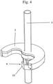
- the counter-retaining element is particularly preferably designed in the shape of a kidney. This has the advantage that water-carrying hoses extending from the fitting body through the recess are also guided through the counter-retaining element.
- the opening for the threaded rod is located on the back-up member such that the outer portions of the back-up member support a large area of the vanity base.
- the counter-holding element can have additional holes for water-carrying hoses or pipes.
- the counter-retaining element is designed in one piece. In particular, it has a conical reduction in the opening for the threaded rod.
- the counter-holding element is formed from two or more parts.
- the conical reduction in the opening is formed only in one or in several parts of the counter-retaining element arranged below.
- a core diameter of the internal thread of the nut is larger than a nominal diameter of the external thread of the thread rod.
- the nut is oversized compared to the threaded rod. The fact that in particular the core diameter of the internal thread of the nut is larger than the nominal diameter of the external thread of the threaded rod, the nut can also in unmachined areas of the threaded rod on the threaded rod are moved. Any thread faults that would lead to the nut jamming on the threaded rod can also be overcome without contact. In particular, an easy and quick attachment of the sanitary fitting during assembly is thus possible.
- a core diameter of the internal thread of the nut is equal to or smaller than a nominal diameter of the external thread of the threaded rod.
- the nut can be slid onto the threaded rod in the manner of a ratchet.
- the thread flanks of the internal thread of the nut and the external thread of the threaded rod are aligned in the axial direction or overlap. Consequently, the nut can be pushed onto the threaded rod with a certain resistance.
- a tool is used to push the nut onto the threaded rod, which facilitates the ratchet-like pushing on.
- the jacket sections of the nut can advantageously be deflected outwards through the interaction of the threads, so that sliding on is additionally simplified.
- the nut can advantageously be pushed up to a desired position on the threaded rod and held in this position.
- the nut can thus advantageously be held captively on the threaded rod during assembly after a first initial sliding on.
- the nut can advantageously not slip off the threaded rod in an uncontrolled manner after it has been loosened.
- the nut has at least three, preferably four or more longitudinal recesses that are offset from one another in the circumferential direction. Consequently, the mother has three or more deflectable shell sections, which are advantageously easily deflected and allow a more uniform application of the shell sections to the threaded rod.
- An exemplary disassembling process of the fastening device according to the invention is performed in reverse order of the assembling process, wherein tightening of the nut is replaced by loosening of the nut, and pushing on is replaced by pulling off, and letting in is replaced by taking out.
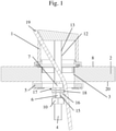
- the sanitary fitting shown in the figures comprises a fitting body 1 which is connected to a threaded rod 4 which can be guided through a recess 3 in the washbasin 2 . Furthermore, the fitting body 1 is equipped with a push-fit on the threaded rod 4 from below Counter-retaining element 5 and a nut 6 that can be slid onto the threaded rod 4 can be fixed on the vanity unit 2 .
- the wash stand 2 has a wash stand top 8 and a wash stand bottom 20 . Additionally is in figure 1 a pull rod 19 for a drain can be seen.
- the threaded rod 4 is connected to the fitting body 2 and has an external thread 13 with a nominal diameter 12 .
- the counter-holding element 5 is kidney-shaped in the figures (cf figure 2 and 4 ) and has an opening 7 .
- the opening 7 is provided for the threaded rod 4, the opening 7 being circular and larger than the nominal diameter 12 of the external thread 13 of the threaded rod 4 figure 5 to see, in a lower part of the counter-holding element 5, a conical reduction 17 in the area of the opening 7 on.
- the example in figure 2 The nut 6 shown in detail has a drive profile 10 and an internal thread 9 with a core diameter 11 .
- the nut 6 above the drive profile 10 has six longitudinal recesses 15 of the same size and arranged in the same way in relation to a central axis 14 .
- the remaining areas of the nut 6 next to the longitudinal recesses 15 are designed as resilient jacket sections 16 which also have a conical reduction 17 above a contact projection 18 which is designed to complement the conical reduction 17 of the opening 7 of the counter-holding element 5 .
- the nut 6 is oversized compared to the threaded rod 4 and the internal thread 9 of the nut 6, as in particular in figure 5 can be seen is only formed in a region of the jacket sections 16 .
- the fitting body 1 When mounting the sanitary fitting shown in the figures, the fitting body 1 is first on the washbasin 2 on the Washbasin top 8 placed, the threaded rod 4 connected to the fitting body 1 being let into the recess 3 of the washbasin 2 . The bottom of the fitting body 1 rests on the top 8 of the washbasin.
- the counter-holding element 5 with the opening 7 is then pushed straight onto the threaded rod 4 from below.
- the opening 7 of the counter-holding element 5 is larger than the nominal diameter 12 of the external thread 13 of the threaded rod 4, which makes it possible to simply push the counter-holding element 5 along the threaded rod 4 until the counter-holding element 5 comes into contact with the underside 20 of the washbasin.
- the nut 6 is pushed along the threaded rod 4 until the nut 6 abuts against the counter-retaining element 5 .
- the jacket sections 16 are deflected inwards through the conical reductions 17 of the nut 6 and the opening 7 .
- the jacket section 16 comes into contact with the threaded rod 4 , and the internal thread 9 of the nut 6 engages with the external thread 13 of the threaded rod 4 .
- the nut 6 can be further tightened via the drive profile 10 until it reaches a final assembly position (cf figure 5 ) of the mother 6 is coming.
- the contact projection 18 bears against the counter-retaining element 5 with a flat upper side.
- the jacket sections 16 are aligned uniformly in relation to a central axis 14 of the nut 6 and the thread engagement is predetermined by the conical reduction 17 and the arrangement of the contact projection 18.
- the nut 6 is first released by loosening via the drive profile 10 and then pulled off the threaded rod 4 . Thereafter, the counter-holding element 5 can also be pulled off the threaded rod 4 and the fitting body 1 connected to the threaded rod 4 can be removed from the recess 3 of the washbasin 2 .
Landscapes
- Engineering & Computer Science (AREA)
- General Engineering & Computer Science (AREA)
- Health & Medical Sciences (AREA)
- Life Sciences & Earth Sciences (AREA)
- Hydrology & Water Resources (AREA)
- Public Health (AREA)
- Water Supply & Treatment (AREA)
- Mechanical Engineering (AREA)
- Sink And Installation For Waste Water (AREA)
Priority Applications (1)
| Application Number | Priority Date | Filing Date | Title |
|---|---|---|---|
| EP20186244.8A EP3940158A1 (fr) | 2020-07-16 | 2020-07-16 | Armature sanitaire pourvu d'un écrou de montage rapide |
Applications Claiming Priority (1)
| Application Number | Priority Date | Filing Date | Title |
|---|---|---|---|
| EP20186244.8A EP3940158A1 (fr) | 2020-07-16 | 2020-07-16 | Armature sanitaire pourvu d'un écrou de montage rapide |
Publications (1)
| Publication Number | Publication Date |
|---|---|
| EP3940158A1 true EP3940158A1 (fr) | 2022-01-19 |
Family
ID=71661740
Family Applications (1)
| Application Number | Title | Priority Date | Filing Date |
|---|---|---|---|
| EP20186244.8A Withdrawn EP3940158A1 (fr) | 2020-07-16 | 2020-07-16 | Armature sanitaire pourvu d'un écrou de montage rapide |
Country Status (1)
| Country | Link |
|---|---|
| EP (1) | EP3940158A1 (fr) |
Citations (10)
| Publication number | Priority date | Publication date | Assignee | Title |
|---|---|---|---|---|
| DE4403974A1 (de) | 1994-02-08 | 1995-08-10 | Eugene S D Eder | Gewindemutter zur Schnellbefestigung |
| US20070122248A1 (en) * | 2005-11-28 | 2007-05-31 | Ellis Gary L | Quick-connect fastener assembly |
| DE102005057729A1 (de) | 2005-12-01 | 2007-06-21 | Grohe Ag | Schnellbefestigungseinrichtung |
| CA2632368A1 (fr) * | 2008-05-27 | 2009-11-27 | Globe Union Industrial Corp. | Ecrou rapide |
| DE102010006375A1 (de) | 2009-03-09 | 2010-09-16 | Grohe Ag | Sanitärarmatur |
| US20100272503A1 (en) * | 2009-04-22 | 2010-10-28 | As Ip Holdco, L.L.C. | Push and Turn Nut for Quick Faucet Installation |
| US20140124049A1 (en) * | 2012-11-05 | 2014-05-08 | Xiamen Lota International Co., Ltd. | Quick assembly and disassembly mechanism |
| US20150043963A1 (en) * | 2013-08-09 | 2015-02-12 | Globe Union Industrial Corp. | Nut for providing quick assembly and disassembly |
| EP2985477A1 (fr) * | 2014-08-14 | 2016-02-17 | fischerwerke GmbH & Co. KG | Dispositif de fixation et systeme de fixation en particulier destine a fixer un objet sanitaire |
| US20190071848A1 (en) * | 2017-09-06 | 2019-03-07 | Kohler Co. | Faucet fixation system |
-
2020
- 2020-07-16 EP EP20186244.8A patent/EP3940158A1/fr not_active Withdrawn
Patent Citations (10)
| Publication number | Priority date | Publication date | Assignee | Title |
|---|---|---|---|---|
| DE4403974A1 (de) | 1994-02-08 | 1995-08-10 | Eugene S D Eder | Gewindemutter zur Schnellbefestigung |
| US20070122248A1 (en) * | 2005-11-28 | 2007-05-31 | Ellis Gary L | Quick-connect fastener assembly |
| DE102005057729A1 (de) | 2005-12-01 | 2007-06-21 | Grohe Ag | Schnellbefestigungseinrichtung |
| CA2632368A1 (fr) * | 2008-05-27 | 2009-11-27 | Globe Union Industrial Corp. | Ecrou rapide |
| DE102010006375A1 (de) | 2009-03-09 | 2010-09-16 | Grohe Ag | Sanitärarmatur |
| US20100272503A1 (en) * | 2009-04-22 | 2010-10-28 | As Ip Holdco, L.L.C. | Push and Turn Nut for Quick Faucet Installation |
| US20140124049A1 (en) * | 2012-11-05 | 2014-05-08 | Xiamen Lota International Co., Ltd. | Quick assembly and disassembly mechanism |
| US20150043963A1 (en) * | 2013-08-09 | 2015-02-12 | Globe Union Industrial Corp. | Nut for providing quick assembly and disassembly |
| EP2985477A1 (fr) * | 2014-08-14 | 2016-02-17 | fischerwerke GmbH & Co. KG | Dispositif de fixation et systeme de fixation en particulier destine a fixer un objet sanitaire |
| US20190071848A1 (en) * | 2017-09-06 | 2019-03-07 | Kohler Co. | Faucet fixation system |
Similar Documents
| Publication | Publication Date | Title |
|---|---|---|
| DE102010061067B4 (de) | Vorrichtung zur Fixierung eines Kabels an einen Kabelabgangsstutzen | |
| EP1426635B1 (fr) | Système de fixation | |
| DE102014110638A1 (de) | Schnell montierbare und demontierbare Schraubmuffe | |
| EP2921757B1 (fr) | Collier profilé | |
| EP3586018B1 (fr) | Dispositif de fixation et module de fixation | |
| DE102015115890A1 (de) | Anordnung zur Herstellung einer Rohrverbindung und Halteelement für eine solche Anordnung | |
| EP3601865B1 (fr) | Raccord de tube | |
| EP2647896A2 (fr) | Agencement de connexion pour une liaison à brides conique et liaison à brides conique | |
| EP3446019B1 (fr) | Dispositif de raccordement | |
| DE10133063A1 (de) | Befestigungsvorrichtung | |
| DE102015219420B4 (de) | Befestigungsvorrichtung zur Befestigung einer Sanitärarmatur | |
| EP1840441A2 (fr) | Elément de raccordement de tuyau | |
| DE102015120525B4 (de) | Befestigungssystem für einen Toilettensitz, Käfig, Käfigmutter, Verwendung, Anordnung und Verfahren | |
| EP2492566A2 (fr) | Vissage pour le passage étanche de conduites | |
| EP3153755B1 (fr) | Bride compressible à assemblage contrôlé | |
| DE102007042034A1 (de) | Befestigungssystem zum Befestigen von Bauelementen, insbesondere für Kraftfahrzeuge | |
| EP3586013B1 (fr) | Module de fixation | |
| EP3940158A1 (fr) | Armature sanitaire pourvu d'un écrou de montage rapide | |
| DE102016115181A1 (de) | Sanitärarmatur | |
| EP3356688B1 (fr) | Cheville à bascule | |
| EP1571268B1 (fr) | Robinetterie sanitaire | |
| DE202004011202U1 (de) | Moduldichtung für Leitungsdurchführungen | |
| DE19510117C2 (de) | Ankermutter | |
| EP3770347A1 (fr) | Armature sanitaire dotée d'un tube destiné au montage rapide | |
| EP2163291A1 (fr) | Panier d'appui de filtre |
Legal Events
| Date | Code | Title | Description |
|---|---|---|---|
| PUAI | Public reference made under article 153(3) epc to a published international application that has entered the european phase |
Free format text: ORIGINAL CODE: 0009012 |
|
| STAA | Information on the status of an ep patent application or granted ep patent |
Free format text: STATUS: REQUEST FOR EXAMINATION WAS MADE |
|
| 17P | Request for examination filed |
Effective date: 20210914 |
|
| AK | Designated contracting states |
Kind code of ref document: A1 Designated state(s): AL AT BE BG CH CY CZ DE DK EE ES FI FR GB GR HR HU IE IS IT LI LT LU LV MC MK MT NL NO PL PT RO RS SE SI SK SM TR |
|
| STAA | Information on the status of an ep patent application or granted ep patent |
Free format text: STATUS: EXAMINATION IS IN PROGRESS |
|
| 17Q | First examination report despatched |
Effective date: 20220726 |
|
| STAA | Information on the status of an ep patent application or granted ep patent |
Free format text: STATUS: THE APPLICATION IS DEEMED TO BE WITHDRAWN |
|
| 18D | Application deemed to be withdrawn |
Effective date: 20221206 |