EP3939818A1 - Automotive exhaust system isolator - Google Patents
Automotive exhaust system isolator Download PDFInfo
- Publication number
- EP3939818A1 EP3939818A1 EP21184278.6A EP21184278A EP3939818A1 EP 3939818 A1 EP3939818 A1 EP 3939818A1 EP 21184278 A EP21184278 A EP 21184278A EP 3939818 A1 EP3939818 A1 EP 3939818A1
- Authority
- EP
- European Patent Office
- Prior art keywords
- support arms
- isolator
- central member
- isolator according
- peripheral member
- Prior art date
- Legal status (The legal status is an assumption and is not a legal conclusion. Google has not performed a legal analysis and makes no representation as to the accuracy of the status listed.)
- Granted
Links
- 230000002093 peripheral effect Effects 0.000 claims abstract description 45
- 238000006073 displacement reaction Methods 0.000 description 6
- 230000006835 compression Effects 0.000 description 4
- 238000007906 compression Methods 0.000 description 4
- 238000004088 simulation Methods 0.000 description 3
- 238000009826 distribution Methods 0.000 description 2
- 230000003068 static effect Effects 0.000 description 2
- 229920002943 EPDM rubber Polymers 0.000 description 1
- 244000043261 Hevea brasiliensis Species 0.000 description 1
- 239000004952 Polyamide Substances 0.000 description 1
- 229910000831 Steel Inorganic materials 0.000 description 1
- XAGFODPZIPBFFR-UHFFFAOYSA-N aluminium Chemical compound [Al] XAGFODPZIPBFFR-UHFFFAOYSA-N 0.000 description 1
- 229910052782 aluminium Inorganic materials 0.000 description 1
- 239000004411 aluminium Substances 0.000 description 1
- 238000005452 bending Methods 0.000 description 1
- 230000005540 biological transmission Effects 0.000 description 1
- 239000012141 concentrate Substances 0.000 description 1
- 238000005520 cutting process Methods 0.000 description 1
- 229920001971 elastomer Polymers 0.000 description 1
- 239000013536 elastomeric material Substances 0.000 description 1
- 238000005304 joining Methods 0.000 description 1
- 238000004519 manufacturing process Methods 0.000 description 1
- 229920003052 natural elastomer Polymers 0.000 description 1
- 229920001194 natural rubber Polymers 0.000 description 1
- 239000004033 plastic Substances 0.000 description 1
- 229920002647 polyamide Polymers 0.000 description 1
- 239000005060 rubber Substances 0.000 description 1
- 239000010959 steel Substances 0.000 description 1
- 229920002725 thermoplastic elastomer Polymers 0.000 description 1
- 239000004636 vulcanized rubber Substances 0.000 description 1
Images


Classifications
-
- F—MECHANICAL ENGINEERING; LIGHTING; HEATING; WEAPONS; BLASTING
- F01—MACHINES OR ENGINES IN GENERAL; ENGINE PLANTS IN GENERAL; STEAM ENGINES
- F01N—GAS-FLOW SILENCERS OR EXHAUST APPARATUS FOR MACHINES OR ENGINES IN GENERAL; GAS-FLOW SILENCERS OR EXHAUST APPARATUS FOR INTERNAL COMBUSTION ENGINES
- F01N13/00—Exhaust or silencing apparatus characterised by constructional features ; Exhaust or silencing apparatus, or parts thereof, having pertinent characteristics not provided for in, or of interest apart from, groups F01N1/00 - F01N5/00, F01N9/00, F01N11/00
- F01N13/18—Construction facilitating manufacture, assembly, or disassembly
- F01N13/1805—Fixing exhaust manifolds, exhaust pipes or pipe sections to each other, to engine or to vehicle body
- F01N13/1811—Fixing exhaust manifolds, exhaust pipes or pipe sections to each other, to engine or to vehicle body with means permitting relative movement, e.g. compensation of thermal expansion or vibration
- F01N13/1822—Fixing exhaust manifolds, exhaust pipes or pipe sections to each other, to engine or to vehicle body with means permitting relative movement, e.g. compensation of thermal expansion or vibration for fixing exhaust pipes or devices to vehicle body
-
- B—PERFORMING OPERATIONS; TRANSPORTING
- B60—VEHICLES IN GENERAL
- B60K—ARRANGEMENT OR MOUNTING OF PROPULSION UNITS OR OF TRANSMISSIONS IN VEHICLES; ARRANGEMENT OR MOUNTING OF PLURAL DIVERSE PRIME-MOVERS IN VEHICLES; AUXILIARY DRIVES FOR VEHICLES; INSTRUMENTATION OR DASHBOARDS FOR VEHICLES; ARRANGEMENTS IN CONNECTION WITH COOLING, AIR INTAKE, GAS EXHAUST OR FUEL SUPPLY OF PROPULSION UNITS IN VEHICLES
- B60K13/00—Arrangement in connection with combustion air intake or gas exhaust of propulsion units
- B60K13/04—Arrangement in connection with combustion air intake or gas exhaust of propulsion units concerning exhaust
-
- B—PERFORMING OPERATIONS; TRANSPORTING
- B60—VEHICLES IN GENERAL
- B60Y—INDEXING SCHEME RELATING TO ASPECTS CROSS-CUTTING VEHICLE TECHNOLOGY
- B60Y2410/00—Constructional features of vehicle sub-units
- B60Y2410/12—Production or manufacturing of vehicle parts
- B60Y2410/122—Plastic parts manufactured by moulding
-
- F—MECHANICAL ENGINEERING; LIGHTING; HEATING; WEAPONS; BLASTING
- F01—MACHINES OR ENGINES IN GENERAL; ENGINE PLANTS IN GENERAL; STEAM ENGINES
- F01N—GAS-FLOW SILENCERS OR EXHAUST APPARATUS FOR MACHINES OR ENGINES IN GENERAL; GAS-FLOW SILENCERS OR EXHAUST APPARATUS FOR INTERNAL COMBUSTION ENGINES
- F01N2530/00—Selection of materials for tubes, chambers or housings
- F01N2530/22—Flexible elastomeric material
Definitions
- the present invention relates to an automotive exhaust system isolator for suspending a gas exhaust systems of motor vehicles.
- Isolators for suspending exhaust systems of motor vehicles are known. Those isolators are configured for attaching the gas exhaust system, which is subjected to swinging, to a second component, such as the chassis of the vehicle, for example.
- isolators usually are made of rubber and must withstand static loads, for example the weight of the exhaust system that hangs from the isolator, and/or dynamic loads if the exhaust system is subjected to vibrations or swinging, for example.
- One type of isolators can have two opposed fastening areas, usually cylindrical holes, which move away from one another when the isolator is stretched in used and move closer when the isolator is compressed in used.
- a central member which has a through hole for inserting a pin of the exhaust system is moved in used, usually up and down, around a peripheral member which is able to be attached to the vehicle body.
- the central member and the peripheral member are joined by four support arms, two of which are disposed in the upper part of the isolator and the other two in the lower part of the isolator.
- WO2008027110A2 discloses an isolator for an automotive exhaust system comprising an elastomeric body having a central member with a through hole for inserting a pin of an exhaust system, and a peripheral member surrounding the central member and connected to said central member through four support arms, two of which are located in the upper part of the elastomeric body and the other two in the lower part of the elastomeric body.
- the object of the invention is to provide an automotive exhaust system isolator, as defined in the claims.
- the automotive exhaust system isolator of the invention comprises an elastomeric body comprising a central member having a through hole for inserting a pin of an exhaust system, and a peripheral member surrounding the central member and connected to said central member.
- the peripheral member is configured to be coupled to a vehicle body.
- the elastomeric body further comprises two support arms having a first end and a second end.
- the first and second ends of the respective support arms are joined to the peripheral member and the central member is connected to the two support arms by means of respective lateral bridges, so that, in use, the first ends of the support arms are positioned in an upper part of the peripheral member and the second ends are positioned in a lower part of the peripheral member.
- the central member is positioned between both support arms.
- the support arms of the isolator of the invention in use, work mainly in the direction of the supporting load exerted by the suspended exhaust system, i.e. in the vertical direction.
- the central member In use the central member is moved up and down depending on the terrain on which the vehicle circulates, therefore, both support arms work under traction/compression loads instead of flexion loads, which increases the durability of the isolator compared with the isolators of the prior art of the same type.
- FIGS 1 and 2 show an embodiment of the automotive exhaust system isolator 1 of the invention.
- Said isolator 1 is the link between a vehicle body and the gas exhaust system which hangs from the isolator 1.
- the aim of the isolator 1 is to support said exhaust system while the transmission of the vibrations generated by the exhaust system towards the vehicle body is minimized.
- the isolator 1 comprises an elastomeric body 2 comprising a central member 3 having a through hole 3.1 for inserting a mounting pin 12 of an exhaust system, and a peripheral member 4 surrounding the central member 3 and connected to said central member 3.
- the peripheral member 4 is configured to be coupled to a vehicle body.
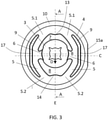
- the elastomeric body 2 further comprises two support arms 5 having a first end 5.1 and a second end 5.2 as best shown in Figure 3 .
- the first and second ends 5.1 and 5.2 of the respective support arms 5 are joined to the peripheral member 4 and the central member 3 is connected to the two support arms 3 by means of respective lateral bridges 6, so that, in use, the first ends 5.1 of the support arms 5 are positioned in an upper part of the peripheral member 4 and the second ends 5.2 are positioned in a lower part of the peripheral member 4.
- the central member 3 is positioned between both support arms 5 as shown in Figures 1 , 2 or 3 .
- the support arms 5 of the isolator 1 of the invention in use, work mainly in the direction of the supporting load, represented in Figure 3 by arrow D, exerted by the suspended exhaust system, i.e. in the vertical direction, so that the durability of the isolator 1 is increased compared with the isolators of the prior art of the same type.
- the central member 3 In use the central member 3 is moved up and down depending on the terrain on which the vehicle circulates.
- the upper part of each support arm 5, i.e. the part above the lateral bridge 6, is deformed and elongated when the central member 3 is moved to the lower side of the isolator 1, i.e. is tensioned, while the opposed part, i.e.
- the part below the lateral bridge 6, is deformed and shortened, i.e. is compressed.
- the central member 3 is moved in use to the upper side of the isolator 1 then the upper part of each support arm 5 is deformed and shortened, i.e. is compressed, and the opposed part, i.e. the part below the lateral bridge 6, is deformed and elongated, i.e. is tensioned. Therefore, both support arms 5 work under traction/compression loads instead of flexion loads, therefore, the durability of the isolator 1 is increased.
- the corresponding support arm is bended and therefore the loads are concentrated around the bending point which can weaken the support arm. Instead, when a support arm has to withstand traction/compression loads, as in the case of the invention, the traction/compression loads are distributed along the whole of the support arm and therefore the durability is increased.
- the elastomeric body of the preferred embodiment is made of natural rubber, vulcanized rubber, thermoplastic elastomer, EPDM and/or any combination among them.
- the use position is to be understood as the position in which the isolator 1 is going to be assembled in the vehicle. In this position the plane of symmetry of the isolator 1 is the vertical plane, said vertical plane being parallel to the cutting section A-A shown in Figure 3 .
- the stable position is to be understood as a position in which the central member 3, where the mounting pin of the exhaust system is not inserted yet in the through hole 3.1, is in a rest position, i.e. without being displaced, as in the position shown in Figure 3 .
- the first ends 5.1 and the second ends 5.2 of the respective support arms 5 are located within a segment of the peripheral member 4 between 0° and 45° from the vertical axis E, being the isolator 1 in the use position and in the stable position, as in the position shown in Figure 3 .
- the lateral bridges 6 are joined to the center of the respective support arms 5 at one of its ends, while the other end is joined to the center of the central member 3 as shown in Figure 3 .
- the respective lateral bridges 6 are tilted up so that the central axis B of the central member 3 is disposed above the central axis C of the peripheral member 4, as best shown in Figure 3 .
- the central member 3 When the exhaust system is hanged from the isolator 1 through the through hole 3.1 of the central member 3, the central member 3 is displaced downwards due to the weight of the exhaust system, and therefore the central axis B of the central member 3 is also displaced, preferably until the central axis B of the central member 3 coincides with the central axis C of the peripheral member 4.
- the lateral bridges 6 and the central member 3 are designed to make this happen.
- each support arm 5 and the central member 3 may be joined by two lateral bridges 6, one lateral bridge 6 being joined at one end within a section of the upper part of the central member 3 and at the other end within a section of the upper part of the respective support arm 5, the second lateral bridge 6 being disposed in a lower position of the first lateral bridge 6, in such a way that the central axis B of the central member 3 is arranged above the central axis C of the peripheral member 4 when the isolator 1 is in the use position and in the stable position.
- the support arms 5 of the isolator 1 of the invention have a C shape and an inverted C shape respectively, and each of them partially surrounds the central member 3. Being the isolator 1 in the use position and in the stable position, as in the position shown in Figure 3 , one support arm 5 is the mirror image of the other.
- first ends 5.1 of the two support arms 5 are joined to each other in the upper part of the peripheral member 4 and the second ends 5.2. of the two support arms 5 are joined to each other in the lower part of the peripheral member 4. This allows to a better distribution of the loads towards the support arms 5 since a more balanced load distribution is made possible.
- an upper buffer hole 7 is formed between the upper portions of both support arms 5, i.e. above the lateral bridges 6 or above the center of the support arms 5, and between the upper part of the central member 3 and the inner side of the upper part of the peripheral member 4.
- Said upper buffer hole 7 runs through the elastomeric body 2 from side to side and has an inverted U shape when the isolator 1 is in the use position and in the stable position, as in the position shown in Figure 3 .
- a lower buffer hole 8 is formed between lower portion of both support arms 5, i.e. below the lateral bridges 6 or below the center of the support arms 5, and between the lower part of the central member 3 and the inner side of the lower part of the peripheral member 4.
- Said lower buffer hole 8 also runs through the elastomeric body 2 from side to side and has a U shape when the isolator 1 is in the use position and in the stable position, as in the position shown in Figure 3 .
- both upper buffer hole 7 and lower buffer hole 8 tend to equalize in size.
- the isolator 1 of the invention further comprises lateral buffer holes 9 formed between the peripheral member 4 and the corresponding support arm 5.
- Said lateral buffer holes 9 are through holes running through the elastomeric body 2 from side to side.
- the lateral buffer holes 9 have a C shape and an inverted C shape respectively. Being the isolator 1 in the use position and in the stable position, as in the position shown in Figure 3 , one lateral buffer hole 9 is the mirror image of the other.
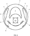
- FIG. 6 shows an image of the simulation of an example of the behavior of the isolator 1 when it is in use.
- the central member 3 has been moved to the lower position of the isolator 1.
- the upper buffer hole 7 and the upper part of the lateral buffer holes 9 have been enlarged allowing the upper part of the respective support arms 5 to be also enlarged, i.e. tensioned, while the lower buffer hole 8 and the lower part of the lateral buffer holes 9 having been almost disappeared, allowing the lower part of the respective support arms 5 to be shortened, i.e. compressed.
- the upper buffer hole 7, the lower buffer hole 8 and the lateral buffer holes 9 are through holes that run through the elastomeric body 2 from side to side allow to dissipate the high temperature that concentrates near the isolator 1 when it is in use due to the high temperatures at which the exhaust system works.
- the inner side of the upper part of the peripheral member 4, preferably where the first ends 5.1 of the respective support arms 5 are joined, comprise a limiting protrusion 13 as shown in Figure 3 , which makes the upper buffer hole 7 to be narrower in the symmetry vertical plane.
- the inner side of the lower part of the peripheral member 4, preferably where the second ends 5.2 of the respective support arms 5 are joined, comprise a limiting protrusion 14 as shown in Figure 3 , which makes the lower buffer hole 8 to be narrower in the symmetry vertical plane.
- Those limiting protrusions 13 and 14 limit the displacement of the central member 3 when the isolator 1 is in use in the vehicle. This is advantageous in order not to exceed an undesired deformation of the support arms 5 so that the threshold of the yield point of the elastomeric body 2 is not exceeded.
- the maximum displacement of the exhaust system is also limited, avoiding any undesired contact of the exhaust system with the surrounding components of the vehicle. The simulation of Figure 6 has been made without the limiting protrusions 13 and 14.
- each of the lateral buffer holes 9 comprises a straight section 17, i.e. a section which is parallel to the direction of the supporting load, represented in Figure 3 by arrow D, exerted by the hanged exhaust system, i.e. in the vertical direction, preferably located in the middle zone of the corresponding lateral buffer hole 9.
- This allows the deformation of the corresponding support arm 5 to be the desired one, although there is lack of space, allowing the maximum displacement of the central member 3.
- Said maximum displacement of the central member 3 is achieved when the central member 3 contacts against the upper or lower part of the peripheral member 4 (the isolator 1 being in the use position), covering all stroke between upper and lower buffer holes 7 and 8. If the peripheral member 4 comprises the limiting protrusions 13 and 14, then the maximum displacement of the central member 3 would be achieved when the central member 3 contacts against any of those limiting protrusions 13 or 14.
- the straight section 17 of the lateral buffer holes 9 guarantees that the corresponding support arm 5 does not collapse against the wall of the corresponding lateral buffer hole 9 before the central member 3 contacts against the peripheral member 4 or the limiting protrusions 13 or 14. To achieve this, the gap of the respective lateral buffer holes 9 would have to be wide enough and sometimes it might require an enlargement of the peripheral member 4. Sometimes this may not be possible due to lack of space, but thanks to the straight section 17 of the lateral buffer holes 9, the maximum displacement of the central member 3 is guaranteed without enlarging the isolator 1.
- the outermost surface of the peripheral member 4 is surrounded by an outer rigid sleeve 10.
- Said outer sleeve 10 is able to couple to the vehicle body directly or through another component, not shown in the drawings, which is suitable for being attached to the vehicle body.
- the outer sleeve 10 comprises a radially extending protrusion 15, preferably ring shaped, at one of its ends having a recess 15a in a lateral.
- This recess 15 allows the correct assembly of the isolator 1 in the vehicle.
- the correct position of the isolator 1 to be assembled is the one shown in Figure 3 , i.e. the one on which the lower buffer hole 8, which in the use position and the rest position is bigger than the upper buffer hole 7, is located in the lower part of the elastomeric body 2.
- the elastomeric body 2 is overmolded in said outer sleeve 10 but other ways of joining the outer sleeve 10 and the elastomeric body 2 are not ruled out, for example by press-fit.
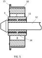
- the central member 3 of the isolator 1 of the invention comprises an embedded rigid inner sleeve 11 as shown in Figures 3 or 4 .
- Said inner sleeve 11 comprises a plurality of holes 16, as shown for example in Figure 4 , to allow the pass of the elastomeric material towards the inner area of the inner sleeve 11 in the manufacturing process.
- the outer sleeve 10 and the inner sleeve 9 are preferably metallic, such as aluminium or steel, but can also be plastic such as polyamide and they allow the isolator 1 to withstand not only the weight of the exhaust system but also the loads (static and dynamics such as swinging loads) exerted by said exhaust system during use.
Abstract
Description
- The present invention relates to an automotive exhaust system isolator for suspending a gas exhaust systems of motor vehicles.
- Isolators for suspending exhaust systems of motor vehicles are known. Those isolators are configured for attaching the gas exhaust system, which is subjected to swinging, to a second component, such as the chassis of the vehicle, for example.
- These isolators usually are made of rubber and must withstand static loads, for example the weight of the exhaust system that hangs from the isolator, and/or dynamic loads if the exhaust system is subjected to vibrations or swinging, for example.
- One type of isolators can have two opposed fastening areas, usually cylindrical holes, which move away from one another when the isolator is stretched in used and move closer when the isolator is compressed in used.
- In another type of isolators, a central member which has a through hole for inserting a pin of the exhaust system is moved in used, usually up and down, around a peripheral member which is able to be attached to the vehicle body. The central member and the peripheral member are joined by four support arms, two of which are disposed in the upper part of the isolator and the other two in the lower part of the isolator.
- In this sense,
WO2008027110A2 discloses an isolator for an automotive exhaust system comprising an elastomeric body having a central member with a through hole for inserting a pin of an exhaust system, and a peripheral member surrounding the central member and connected to said central member through four support arms, two of which are located in the upper part of the elastomeric body and the other two in the lower part of the elastomeric body. - The object of the invention is to provide an automotive exhaust system isolator, as defined in the claims.
- The automotive exhaust system isolator of the invention comprises an elastomeric body comprising a central member having a through hole for inserting a pin of an exhaust system, and a peripheral member surrounding the central member and connected to said central member. The peripheral member is configured to be coupled to a vehicle body.
- The elastomeric body further comprises two support arms having a first end and a second end. The first and second ends of the respective support arms are joined to the peripheral member and the central member is connected to the two support arms by means of respective lateral bridges, so that, in use, the first ends of the support arms are positioned in an upper part of the peripheral member and the second ends are positioned in a lower part of the peripheral member. The central member is positioned between both support arms.
- The support arms of the isolator of the invention, in use, work mainly in the direction of the supporting load exerted by the suspended exhaust system, i.e. in the vertical direction. In use the central member is moved up and down depending on the terrain on which the vehicle circulates, therefore, both support arms work under traction/compression loads instead of flexion loads, which increases the durability of the isolator compared with the isolators of the prior art of the same type.
- These and other advantages and features of the invention will become evident in view of the drawings and detailed description of the invention.
-
-
Figure 1 shows first perspective view of the automotive exhaust system isolator according to the invention. -
Figure 2 shows another perspective view of the isolator ofFigure 1 . -
Figure 3 shows a front view of the isolator ofFigure 1 . -
Figure 4 shows section A-A ofFigure 3 . -
Figure 5 shows section A-A ofFigure 3 but with the pin of the exhaust system. -
Figure 6 shows an image of the simulation of an example of the behavior in use of the isolator ofFigure 1 when the central member has been moved to the lower position. -
Figures 1 and2 show an embodiment of the automotiveexhaust system isolator 1 of the invention. Saidisolator 1 is the link between a vehicle body and the gas exhaust system which hangs from theisolator 1. In use the gas exhaust system of a vehicle is subjected to swinging loads, therefore the aim of theisolator 1 is to support said exhaust system while the transmission of the vibrations generated by the exhaust system towards the vehicle body is minimized. - The
isolator 1 comprises anelastomeric body 2 comprising acentral member 3 having a through hole 3.1 for inserting amounting pin 12 of an exhaust system, and aperipheral member 4 surrounding thecentral member 3 and connected to saidcentral member 3. Theperipheral member 4 is configured to be coupled to a vehicle body. - The
elastomeric body 2 further comprises twosupport arms 5 having a first end 5.1 and a second end 5.2 as best shown inFigure 3 . The first and second ends 5.1 and 5.2 of therespective support arms 5 are joined to theperipheral member 4 and thecentral member 3 is connected to the twosupport arms 3 by means of respectivelateral bridges 6, so that, in use, the first ends 5.1 of thesupport arms 5 are positioned in an upper part of theperipheral member 4 and the second ends 5.2 are positioned in a lower part of theperipheral member 4. Thecentral member 3 is positioned between both supportarms 5 as shown inFigures 1 ,2 or3 . - The
support arms 5 of theisolator 1 of the invention, in use, work mainly in the direction of the supporting load, represented inFigure 3 by arrow D, exerted by the suspended exhaust system, i.e. in the vertical direction, so that the durability of theisolator 1 is increased compared with the isolators of the prior art of the same type. In use thecentral member 3 is moved up and down depending on the terrain on which the vehicle circulates. The upper part of eachsupport arm 5, i.e. the part above thelateral bridge 6, is deformed and elongated when thecentral member 3 is moved to the lower side of theisolator 1, i.e. is tensioned, while the opposed part, i.e. the part below thelateral bridge 6, is deformed and shortened, i.e. is compressed. When thecentral member 3 is moved in use to the upper side of theisolator 1 then the upper part of eachsupport arm 5 is deformed and shortened, i.e. is compressed, and the opposed part, i.e. the part below thelateral bridge 6, is deformed and elongated, i.e. is tensioned. Therefore, both supportarms 5 work under traction/compression loads instead of flexion loads, therefore, the durability of theisolator 1 is increased. When a support arm has to withstand flexion loads, the corresponding support arm is bended and therefore the loads are concentrated around the bending point which can weaken the support arm. Instead, when a support arm has to withstand traction/compression loads, as in the case of the invention, the traction/compression loads are distributed along the whole of the support arm and therefore the durability is increased. - The elastomeric body of the preferred embodiment is made of natural rubber, vulcanized rubber, thermoplastic elastomer, EPDM and/or any combination among them.
- According to the preferred embodiment, the
isolator 1, being in a use position and in a stable position (as in the position shown inFigure 3 ), is symmetric with respect to a vertical plane. In the context of the invention, the use position is to be understood as the position in which theisolator 1 is going to be assembled in the vehicle. In this position the plane of symmetry of theisolator 1 is the vertical plane, said vertical plane being parallel to the cutting section A-A shown inFigure 3 . In the same way, the stable position is to be understood as a position in which thecentral member 3, where the mounting pin of the exhaust system is not inserted yet in the through hole 3.1, is in a rest position, i.e. without being displaced, as in the position shown inFigure 3 . - The first ends 5.1 and the second ends 5.2 of the
respective support arms 5 are located within a segment of theperipheral member 4 between 0° and 45° from the vertical axis E, being theisolator 1 in the use position and in the stable position, as in the position shown inFigure 3 . - In the preferred embodiment, the
lateral bridges 6 are joined to the center of therespective support arms 5 at one of its ends, while the other end is joined to the center of thecentral member 3 as shown inFigure 3 . Being theisolator 1 in the use position and in the stable position, the respectivelateral bridges 6 are tilted up so that the central axis B of thecentral member 3 is disposed above the central axis C of theperipheral member 4, as best shown inFigure 3 . When the exhaust system is hanged from theisolator 1 through the through hole 3.1 of thecentral member 3, thecentral member 3 is displaced downwards due to the weight of the exhaust system, and therefore the central axis B of thecentral member 3 is also displaced, preferably until the central axis B of thecentral member 3 coincides with the central axis C of theperipheral member 4. Thelateral bridges 6 and thecentral member 3 are designed to make this happen. - In a variant of the invention, each
support arm 5 and thecentral member 3 may be joined by twolateral bridges 6, onelateral bridge 6 being joined at one end within a section of the upper part of thecentral member 3 and at the other end within a section of the upper part of therespective support arm 5, the secondlateral bridge 6 being disposed in a lower position of the firstlateral bridge 6, in such a way that the central axis B of thecentral member 3 is arranged above the central axis C of theperipheral member 4 when theisolator 1 is in the use position and in the stable position. - As best shown in
Figure 3 , thesupport arms 5 of theisolator 1 of the invention have a C shape and an inverted C shape respectively, and each of them partially surrounds thecentral member 3. Being theisolator 1 in the use position and in the stable position, as in the position shown inFigure 3 , onesupport arm 5 is the mirror image of the other. - In the preferred embodiment of the invention the first ends 5.1 of the two
support arms 5 are joined to each other in the upper part of theperipheral member 4 and the second ends 5.2. of the twosupport arms 5 are joined to each other in the lower part of theperipheral member 4. This allows to a better distribution of the loads towards thesupport arms 5 since a more balanced load distribution is made possible. - In the preferred embodiment of the invention an
upper buffer hole 7 is formed between the upper portions of both supportarms 5, i.e. above thelateral bridges 6 or above the center of thesupport arms 5, and between the upper part of thecentral member 3 and the inner side of the upper part of theperipheral member 4. Saidupper buffer hole 7 runs through theelastomeric body 2 from side to side and has an inverted U shape when theisolator 1 is in the use position and in the stable position, as in the position shown inFigure 3 . - In the same way, a
lower buffer hole 8 is formed between lower portion of both supportarms 5, i.e. below thelateral bridges 6 or below the center of thesupport arms 5, and between the lower part of thecentral member 3 and the inner side of the lower part of theperipheral member 4. Saidlower buffer hole 8 also runs through theelastomeric body 2 from side to side and has a U shape when theisolator 1 is in the use position and in the stable position, as in the position shown inFigure 3 . Being theisolator 1 in the use position and the stable position theupper buffer hole 7 is smaller than thelower buffer hole 8 but when the exhaust system is hanged from theisolator 1 through the through hole 3.1, and the vehicle being in a rest position, bothupper hole 7 andlower buffer hole 8 tend to equalize in size. - The
isolator 1 of the invention, according to the preferred embodiment, further compriseslateral buffer holes 9 formed between theperipheral member 4 and thecorresponding support arm 5. Saidlateral buffer holes 9 are through holes running through theelastomeric body 2 from side to side. As best shown inFigure 3 , the lateral buffer holes 9 have a C shape and an inverted C shape respectively. Being theisolator 1 in the use position and in the stable position, as in the position shown inFigure 3 , onelateral buffer hole 9 is the mirror image of the other. - The upper and
lower buffer holes support arms 5 to deform when theisolator 1 is in use, changing temporarily their shape.Figure 6 shows an image of the simulation of an example of the behavior of theisolator 1 when it is in use. In this example, thecentral member 3 has been moved to the lower position of theisolator 1. InFigure 6 can be seen that theupper buffer hole 7 and the upper part of the lateral buffer holes 9 have been enlarged allowing the upper part of therespective support arms 5 to be also enlarged, i.e. tensioned, while thelower buffer hole 8 and the lower part of the lateral buffer holes 9 having been almost disappeared, allowing the lower part of therespective support arms 5 to be shortened, i.e. compressed. - The fact that the
upper buffer hole 7, thelower buffer hole 8 and the lateral buffer holes 9 are through holes that run through theelastomeric body 2 from side to side allow to dissipate the high temperature that concentrates near theisolator 1 when it is in use due to the high temperatures at which the exhaust system works. - The inner side of the upper part of the
peripheral member 4, preferably where the first ends 5.1 of therespective support arms 5 are joined, comprise a limitingprotrusion 13 as shown inFigure 3 , which makes theupper buffer hole 7 to be narrower in the symmetry vertical plane. - In the same way, the inner side of the lower part of the
peripheral member 4, preferably where the second ends 5.2 of therespective support arms 5 are joined, comprise a limitingprotrusion 14 as shown inFigure 3 , which makes thelower buffer hole 8 to be narrower in the symmetry vertical plane. - Those limiting
protrusions central member 3 when theisolator 1 is in use in the vehicle. This is advantageous in order not to exceed an undesired deformation of thesupport arms 5 so that the threshold of the yield point of theelastomeric body 2 is not exceeded. In addition, the maximum displacement of the exhaust system is also limited, avoiding any undesired contact of the exhaust system with the surrounding components of the vehicle. The simulation ofFigure 6 has been made without the limitingprotrusions - As best shown in
Figure 3 , each of the lateral buffer holes 9 comprises astraight section 17, i.e. a section which is parallel to the direction of the supporting load, represented inFigure 3 by arrow D, exerted by the hanged exhaust system, i.e. in the vertical direction, preferably located in the middle zone of the correspondinglateral buffer hole 9. This allows the deformation of thecorresponding support arm 5 to be the desired one, although there is lack of space, allowing the maximum displacement of thecentral member 3. Said maximum displacement of thecentral member 3 is achieved when thecentral member 3 contacts against the upper or lower part of the peripheral member 4 (theisolator 1 being in the use position), covering all stroke between upper andlower buffer holes peripheral member 4 comprises the limitingprotrusions central member 3 would be achieved when thecentral member 3 contacts against any of those limitingprotrusions - Therefore, the
straight section 17 of the lateral buffer holes 9 guarantees that thecorresponding support arm 5 does not collapse against the wall of the correspondinglateral buffer hole 9 before thecentral member 3 contacts against theperipheral member 4 or the limitingprotrusions peripheral member 4. Sometimes this may not be possible due to lack of space, but thanks to thestraight section 17 of the lateral buffer holes 9, the maximum displacement of thecentral member 3 is guaranteed without enlarging theisolator 1. - According to the preferred embodiment of the invention, the outermost surface of the
peripheral member 4 is surrounded by an outerrigid sleeve 10. Saidouter sleeve 10 is able to couple to the vehicle body directly or through another component, not shown in the drawings, which is suitable for being attached to the vehicle body. - As shown in
Figures 1 ,2 or3 , theouter sleeve 10 comprises aradially extending protrusion 15, preferably ring shaped, at one of its ends having arecess 15a in a lateral. Thisrecess 15 allows the correct assembly of theisolator 1 in the vehicle. The correct position of theisolator 1 to be assembled is the one shown inFigure 3 , i.e. the one on which thelower buffer hole 8, which in the use position and the rest position is bigger than theupper buffer hole 7, is located in the lower part of theelastomeric body 2. - In the preferred embodiment the
elastomeric body 2 is overmolded in saidouter sleeve 10 but other ways of joining theouter sleeve 10 and theelastomeric body 2 are not ruled out, for example by press-fit. - The
central member 3 of theisolator 1 of the invention comprises an embedded rigidinner sleeve 11 as shown inFigures 3 or4 . Saidinner sleeve 11 comprises a plurality ofholes 16, as shown for example inFigure 4 , to allow the pass of the elastomeric material towards the inner area of theinner sleeve 11 in the manufacturing process. - The
outer sleeve 10 and theinner sleeve 9 are preferably metallic, such as aluminium or steel, but can also be plastic such as polyamide and they allow theisolator 1 to withstand not only the weight of the exhaust system but also the loads (static and dynamics such as swinging loads) exerted by said exhaust system during use.
Claims (15)
- Automotive exhaust system isolator comprising an elastomeric body (2) comprisinga central member (3) having a through hole (3.1) for inserting a pin (12) of an exhaust system, anda peripheral member (4) surrounding the central member (3) and connected to said central member (3), the peripheral member (4) being configured to be coupled to a vehicle body,characterized in that the elastomeric body (2) further comprises two support arms (5) having a first end (5.1) end a second end (5.2), the first and second ends (5.1, 5.2) of the respective support arms (5) being joined to the peripheral member (4), and the central member (3) being connected to the two support arms (5) by means of respective lateral bridges (6), so that, in use, the first ends (5.1) of the support arms (5) are positioned in an upper part of the peripheral member (4) and the second ends (5.2) are positioned in a lower part of the peripheral member (4), the central member (3) being positioned between both support arms (5).
- Isolator according to claim 1, wherein the support arms (5) have a C shape and an inverted C shape respectively, so that each support arm (5) partially surrounds the central member (3).
- Isolator according to claim 2, wherein the first ends (5.1) of the two support arms (5) are joined to each other in the upper part of the peripheral member (4).
- Isolator according to claim 2 or 3, wherein the second ends (5.2) of the two support arms (5) are joined to each other in the lower part of the peripheral member (4).
- Isolator according to any of the preceding claims, wherein the lateral bridges (6) are joined to the center of the respective support arms (5).
- Isolator according to any of the preceding claims, wherein the lateral bridges (6) are joined to the center of the central member (3).
- Isolator according to any of claims 1 to 4, wherein each support arm (5) and the central member (3) are joined by means of two lateral bridges (6), so that, in use, one lateral bridge (6) is joined to an upper part of the central member (3) and to an upper part of the respective support arm (5), the second lateral bridge (6) being disposed below the first bridge (6).
- Isolator according to any of the preceding claims, wherein the central axis (B) of the central member (3) is disposed, in a use position and in a stable position, above the central axis (C) of the peripheral member (4).
- Isolator according to any of the preceding claims, wherein, in a use position and in a stable position, the isolator (1) is symmetric with respect to a vertical plane.
- Isolator according to any of the preceding claims, wherein the elastomeric body (2) comprises an upper buffer hole (7) formed between the upper portions of both support arms (5), a lower buffer hole (8) formed between the lower portions of both support arms (5) and lateral buffer holes (9) formed between the peripheral member (4) and the corresponding support arm (5).
- Isolator according to claim 10, wherein in a use position each of the lateral buffer holes (9) comprises a vertical straight section (17), preferably located in the middle zone of the corresponding lateral buffer hole (9).
- Isolator according to any of the preceding claims, wherein in a use position the first end (5.1) of each support arm (5) is located within a segment of the upper part of the peripheral member (4) between 0° and 45° from a central vertical axis.
- Isolator according to any of the preceding claims, wherein in a use position the second end (5.2) of each support arm (5) is located within a segment of the upper part of the peripheral member (4) between 0° and 45° from a central vertical axis.
- Isolator according to any of the preceding claims, wherein the outermost surface of the peripheral member (4) is surrounded by an outer rigid sleeve (10).
- Isolator according to any of the preceding claims, wherein the central member (3) comprises an embedded rigid inner sleeve (11).
Applications Claiming Priority (1)
| Application Number | Priority Date | Filing Date | Title |
|---|---|---|---|
| EP20382627 | 2020-07-13 |
Publications (3)
| Publication Number | Publication Date |
|---|---|
| EP3939818A1 true EP3939818A1 (en) | 2022-01-19 |
| EP3939818C0 EP3939818C0 (en) | 2024-02-21 |
| EP3939818B1 EP3939818B1 (en) | 2024-02-21 |
Family
ID=71741748
Family Applications (1)
| Application Number | Title | Priority Date | Filing Date |
|---|---|---|---|
| EP21184278.6A Active EP3939818B1 (en) | 2020-07-13 | 2021-07-07 | Automotive exhaust system isolator |
Country Status (3)
| Country | Link |
|---|---|
| US (1) | US11635013B2 (en) |
| EP (1) | EP3939818B1 (en) |
| CN (1) | CN216331410U (en) |
Families Citing this family (1)
| Publication number | Priority date | Publication date | Assignee | Title |
|---|---|---|---|---|
| CN108010090B (en) * | 2018-01-12 | 2024-03-29 | 深圳市道通科技股份有限公司 | Calibration equipment for vehicle-mounted night vision camera device |
Citations (4)
| Publication number | Priority date | Publication date | Assignee | Title |
|---|---|---|---|---|
| EP0670233A2 (en) * | 1994-03-02 | 1995-09-06 | HENNIGES ELASTOMER- UND KUNSTSTOFFTECHNIK GMBH & CO KG | Resilient mounting of parts on motor vehicles |
| DE19741462C1 (en) * | 1997-09-19 | 1999-05-12 | Draebing Kg Wegu | Elastic mounting |
| WO2008027110A2 (en) | 2006-08-29 | 2008-03-06 | The Pullman Company | Exhaust isolator |
| KR102032825B1 (en) * | 2019-01-23 | 2019-10-16 | 주식회사 디엠씨 | Isolator hanger |
Family Cites Families (13)
| Publication number | Priority date | Publication date | Assignee | Title |
|---|---|---|---|---|
| US4817909A (en) * | 1987-12-07 | 1989-04-04 | Gencorp Inc. | Elastomeric hanger structure |
| US5829732A (en) * | 1996-03-27 | 1998-11-03 | Toyo Tire & Rubber Co., Ltd. | Exhaust pipe supporting device |
| FR2805870B1 (en) * | 2000-03-06 | 2002-06-14 | Hutchinson | ELASTIC SUSPENSION DEVICE FROM A VIBRATING STRUCTURE TO A RIGID STRUCTURE |
| JP4589612B2 (en) * | 2003-09-05 | 2010-12-01 | 株式会社ブリヂストン | Vibration isolator |
| JP4484245B2 (en) * | 2006-12-28 | 2010-06-16 | 東海ゴム工業株式会社 | Muffler hanger |
| JP4959453B2 (en) * | 2007-07-17 | 2012-06-20 | 東海ゴム工業株式会社 | Exhaust pipe support device |
| JP5473884B2 (en) * | 2010-12-09 | 2014-04-16 | 東洋ゴム工業株式会社 | Vibration isolator |
| JP5763380B2 (en) * | 2011-03-22 | 2015-08-12 | 株式会社ブリヂストン | Torque rod |
| US8820701B1 (en) * | 2012-11-28 | 2014-09-02 | Brunswick Corporation | Mounts, mounting arrangements, and methods of making mounting arrangements for supporting outboard motors with respect to marine vessels |
| KR102428835B1 (en) | 2015-10-08 | 2022-08-04 | 한온시스템 주식회사 | Carrier for Motor Vehicle |
| KR101748434B1 (en) | 2016-11-17 | 2017-06-28 | 주식회사 디엠씨 | hanger for fixing the exhaust pipe of a car |
| KR102394805B1 (en) * | 2017-11-24 | 2022-05-04 | 현대자동차주식회사 | Sub-roll rod device for mounting power train of vehicle |
| US10801391B2 (en) * | 2018-04-04 | 2020-10-13 | Ford Global Technologies, Llc | Vibration damping isolator for a vehicle |
-
2020
- 2020-10-09 US US17/066,977 patent/US11635013B2/en active Active
-
2021
- 2021-07-07 EP EP21184278.6A patent/EP3939818B1/en active Active
- 2021-07-08 CN CN202121552388.8U patent/CN216331410U/en active Active
Patent Citations (4)
| Publication number | Priority date | Publication date | Assignee | Title |
|---|---|---|---|---|
| EP0670233A2 (en) * | 1994-03-02 | 1995-09-06 | HENNIGES ELASTOMER- UND KUNSTSTOFFTECHNIK GMBH & CO KG | Resilient mounting of parts on motor vehicles |
| DE19741462C1 (en) * | 1997-09-19 | 1999-05-12 | Draebing Kg Wegu | Elastic mounting |
| WO2008027110A2 (en) | 2006-08-29 | 2008-03-06 | The Pullman Company | Exhaust isolator |
| KR102032825B1 (en) * | 2019-01-23 | 2019-10-16 | 주식회사 디엠씨 | Isolator hanger |
Also Published As
| Publication number | Publication date |
|---|---|
| EP3939818C0 (en) | 2024-02-21 |
| US11635013B2 (en) | 2023-04-25 |
| EP3939818B1 (en) | 2024-02-21 |
| US20220010717A1 (en) | 2022-01-13 |
| CN216331410U (en) | 2022-04-19 |
Similar Documents
| Publication | Publication Date | Title |
|---|---|---|
| EP3032138B1 (en) | Vibration damping device | |
| EP2977639A1 (en) | Spring rubber seat, and strut-type suspension | |
| US9731586B2 (en) | Mount apparatus | |
| EP1666296A1 (en) | Vibration isolation device | |
| KR100476304B1 (en) | Reinforced elastomeric spring and elastomeric spring assembly | |
| JP2002254911A (en) | Vibration isolating sleeve, and car having the sleeve | |
| EP3939818B1 (en) | Automotive exhaust system isolator | |
| CN111806182A (en) | Single shell spring control arm | |
| EP2502764A1 (en) | Stabilizer link for a vehicle suspension and method for obtaining it | |
| JPH09175139A (en) | Fitting part for connecting stabilizer end part with member | |
| EP3269614A1 (en) | Cylindrical elastic coupling device for axle arms | |
| CN102483116B (en) | Mounting element for attaching an assembly | |
| WO2015045041A1 (en) | Cylindrical antivibration device | |
| US5158271A (en) | Automotive powertrain mount | |
| US6145821A (en) | Cylinder-shaped vibration isolator | |
| US4586840A (en) | Elastic joint | |
| JP6276008B2 (en) | Vehicle bushing and chassis frame support structure | |
| EP0188824B2 (en) | Pivot connection for fastening a tilting cylinder to the chassis and the tiltable cab of a vehicle | |
| US11598385B2 (en) | Elastic bearing | |
| CN107269726A (en) | Wide-angle junction surface | |
| JP6811597B2 (en) | Anti-vibration bush | |
| CA2011434C (en) | Automotive powertrain mount | |
| JP2001165219A (en) | Vibration control bush and vibration control bush assembly | |
| CN104047991A (en) | Anti-vibration device | |
| RU198354U1 (en) | VEHICLE SUPPORT |
Legal Events
| Date | Code | Title | Description |
|---|---|---|---|
| PUAI | Public reference made under article 153(3) epc to a published international application that has entered the european phase |
Free format text: ORIGINAL CODE: 0009012 |
|
| STAA | Information on the status of an ep patent application or granted ep patent |
Free format text: STATUS: THE APPLICATION HAS BEEN PUBLISHED |
|
| AK | Designated contracting states |
Kind code of ref document: A1 Designated state(s): AL AT BE BG CH CY CZ DE DK EE ES FI FR GB GR HR HU IE IS IT LI LT LU LV MC MK MT NL NO PL PT RO RS SE SI SK SM TR |
|
| STAA | Information on the status of an ep patent application or granted ep patent |
Free format text: STATUS: REQUEST FOR EXAMINATION WAS MADE |
|
| 17P | Request for examination filed |
Effective date: 20220719 |
|
| RBV | Designated contracting states (corrected) |
Designated state(s): AL AT BE BG CH CY CZ DE DK EE ES FI FR GB GR HR HU IE IS IT LI LT LU LV MC MK MT NL NO PL PT RO RS SE SI SK SM TR |
|
| GRAP | Despatch of communication of intention to grant a patent |
Free format text: ORIGINAL CODE: EPIDOSNIGR1 |
|
| STAA | Information on the status of an ep patent application or granted ep patent |
Free format text: STATUS: GRANT OF PATENT IS INTENDED |
|
| RIC1 | Information provided on ipc code assigned before grant |
Ipc: F01N 13/18 20100101ALI20230921BHEP Ipc: B60K 13/04 20060101AFI20230921BHEP |
|
| INTG | Intention to grant announced |
Effective date: 20231012 |
|
| RAP3 | Party data changed (applicant data changed or rights of an application transferred) |
Owner name: CIKAUTXO, S. COOP. |
|
| GRAS | Grant fee paid |
Free format text: ORIGINAL CODE: EPIDOSNIGR3 |
|
| GRAA | (expected) grant |
Free format text: ORIGINAL CODE: 0009210 |
|
| STAA | Information on the status of an ep patent application or granted ep patent |
Free format text: STATUS: THE PATENT HAS BEEN GRANTED |
|
| AK | Designated contracting states |
Kind code of ref document: B1 Designated state(s): AL AT BE BG CH CY CZ DE DK EE ES FI FR GB GR HR HU IE IS IT LI LT LU LV MC MK MT NL NO PL PT RO RS SE SI SK SM TR |
|
| REG | Reference to a national code |
Ref country code: GB Ref legal event code: FG4D |
|
| REG | Reference to a national code |
Ref country code: CH Ref legal event code: EP |
|
| REG | Reference to a national code |
Ref country code: IE Ref legal event code: FG4D |
|
| REG | Reference to a national code |
Ref country code: DE Ref legal event code: R096 Ref document number: 602021009540 Country of ref document: DE |
|
| U01 | Request for unitary effect filed |
Effective date: 20240305 |
|
| U07 | Unitary effect registered |
Designated state(s): AT BE BG DE DK EE FI FR IT LT LU LV MT NL PT SE SI Effective date: 20240312 |