EP3939748A1 - Tool with protruding structure - Google Patents
Tool with protruding structure Download PDFInfo
- Publication number
- EP3939748A1 EP3939748A1 EP20186368.5A EP20186368A EP3939748A1 EP 3939748 A1 EP3939748 A1 EP 3939748A1 EP 20186368 A EP20186368 A EP 20186368A EP 3939748 A1 EP3939748 A1 EP 3939748A1
- Authority
- EP
- European Patent Office
- Prior art keywords
- tool
- protruding structure
- longitudinal axis
- shaft
- hardened
- Prior art date
- Legal status (The legal status is an assumption and is not a legal conclusion. Google has not performed a legal analysis and makes no representation as to the accuracy of the status listed.)
- Pending
Links
Images
Classifications
-
- B—PERFORMING OPERATIONS; TRANSPORTING
- B23—MACHINE TOOLS; METAL-WORKING NOT OTHERWISE PROVIDED FOR
- B23P—METAL-WORKING NOT OTHERWISE PROVIDED FOR; COMBINED OPERATIONS; UNIVERSAL MACHINE TOOLS
- B23P15/00—Making specific metal objects by operations not covered by a single other subclass or a group in this subclass
-
- B—PERFORMING OPERATIONS; TRANSPORTING
- B25—HAND TOOLS; PORTABLE POWER-DRIVEN TOOLS; MANIPULATORS
- B25D—PERCUSSIVE TOOLS
- B25D17/00—Details of, or accessories for, portable power-driven percussive tools
- B25D17/02—Percussive tool bits
-
- B—PERFORMING OPERATIONS; TRANSPORTING
- B28—WORKING CEMENT, CLAY, OR STONE
- B28D—WORKING STONE OR STONE-LIKE MATERIALS
- B28D1/00—Working stone or stone-like materials, e.g. brick, concrete or glass, not provided for elsewhere; Machines, devices, tools therefor
- B28D1/26—Working stone or stone-like materials, e.g. brick, concrete or glass, not provided for elsewhere; Machines, devices, tools therefor by impact tools, e.g. by chisels or other tools having a cutting edge
-
- C—CHEMISTRY; METALLURGY
- C21—METALLURGY OF IRON
- C21D—MODIFYING THE PHYSICAL STRUCTURE OF FERROUS METALS; GENERAL DEVICES FOR HEAT TREATMENT OF FERROUS OR NON-FERROUS METALS OR ALLOYS; MAKING METAL MALLEABLE, e.g. BY DECARBURISATION OR TEMPERING
- C21D1/00—General methods or devices for heat treatment, e.g. annealing, hardening, quenching or tempering
- C21D1/06—Surface hardening
- C21D1/09—Surface hardening by direct application of electrical or wave energy; by particle radiation
- C21D1/10—Surface hardening by direct application of electrical or wave energy; by particle radiation by electric induction
-
- C—CHEMISTRY; METALLURGY
- C21—METALLURGY OF IRON
- C21D—MODIFYING THE PHYSICAL STRUCTURE OF FERROUS METALS; GENERAL DEVICES FOR HEAT TREATMENT OF FERROUS OR NON-FERROUS METALS OR ALLOYS; MAKING METAL MALLEABLE, e.g. BY DECARBURISATION OR TEMPERING
- C21D1/00—General methods or devices for heat treatment, e.g. annealing, hardening, quenching or tempering
- C21D1/18—Hardening; Quenching with or without subsequent tempering
-
- C—CHEMISTRY; METALLURGY
- C21—METALLURGY OF IRON
- C21D—MODIFYING THE PHYSICAL STRUCTURE OF FERROUS METALS; GENERAL DEVICES FOR HEAT TREATMENT OF FERROUS OR NON-FERROUS METALS OR ALLOYS; MAKING METAL MALLEABLE, e.g. BY DECARBURISATION OR TEMPERING
- C21D1/00—General methods or devices for heat treatment, e.g. annealing, hardening, quenching or tempering
- C21D1/34—Methods of heating
- C21D1/42—Induction heating
-
- Y—GENERAL TAGGING OF NEW TECHNOLOGICAL DEVELOPMENTS; GENERAL TAGGING OF CROSS-SECTIONAL TECHNOLOGIES SPANNING OVER SEVERAL SECTIONS OF THE IPC; TECHNICAL SUBJECTS COVERED BY FORMER USPC CROSS-REFERENCE ART COLLECTIONS [XRACs] AND DIGESTS
- Y02—TECHNOLOGIES OR APPLICATIONS FOR MITIGATION OR ADAPTATION AGAINST CLIMATE CHANGE
- Y02P—CLIMATE CHANGE MITIGATION TECHNOLOGIES IN THE PRODUCTION OR PROCESSING OF GOODS
- Y02P10/00—Technologies related to metal processing
- Y02P10/25—Process efficiency
Definitions
- the present invention relates to a tool, in particular a chisel, for a power tool, the tool having a longitudinal axis and comprising a working section and a shaft with a connection end for connecting the tool to a tool holder of the power tool, wherein the shaft comprises at least one protruding structure protruding from the shaft.
- a first aspect is a tool, in particular a chisel, for a power tool, the tool having a longitudinal axis and comprising a working section and a shaft with a connection end for connecting the tool to a tool holder of the power tool, wherein the shaft comprises at least one protruding structure protruding from the shaft, wherein at least within a first of two halves of the protruding structure, which are separated from each other by a plane perpendicular to the longitudinal axis, the surface of the protruding structure has a finite gradient along a direction parallel to the longitudinal axis.
- the surface of the protruding structure may be formed such that there exists at least one angle in relation to the longitudinal axis, along which the surface of the protruding structure does not even partly shade itself.
- the protruding structure is formed such that its whole surface is accessible along at least one direction, the direction being non-perpendicular to the longitudinal axis. This allows to treat different sections of the tool differentially. For example, the tool may be hardened to different hardnesses depending on the respective section of the tool. Due to the specific surface of the protruding structure, the protruding structure does not stand in its own way during the treatment. Hence, the protruding structure and its surroundings as well as the rest of the tool may be treated in a well-controlled fashion.
- the tool may be a chisel, in particular a pointed chisel or a flat chisel.
- the protruding structure may be part of the connection end.
- at least the shaft and the protruding structure may be formed as one single body.
- the protruding structure may be welded onto and around the shaft.
- the protruding structure may be a ring structure. It may thus form a connection end of a tool for high power tools.
- the protruding structure may be asymmetrical to a center plane of the protruding structure, the center plane being perpendicular to the longitudinal axis.
- the protruding structure and in particular its surface may have two sides, one side facing towards the working section and the other side facing into the counter-direction, i. e. towards a free end of the connection end. At least one of the sides may have a S-shaped or at least a basically S-shaped form.
- a further aspect of the invention is that the tool may be hardened by inductive hardening.
- inductive hardening an applied heating power and a feed rate of the tool may be changed along the entire length of the tool, thus providing a simple way of treating the tool differentially in different sections.
- the tool may be through-hardened and in some sections the tool may be shell-hardened.
- each section of the tool i. e. the chisel
- the tool may contain at least two sections of different microstructure.
- the working section may be through-hardened.
- the working section of the chisel is usually subjected to abrasive stress during e. g. demolition works. Due to wear, the cross-section of the tool decreases continuously, so a through-hardened structure is required in order to prevent the chisel from getting blunt.
- the shaft may be shell-hardened.
- the connection end or at least a part of the connection end may be shell-hardened.
- the surface may be hardened to achieve a hard, wear-resistant layer.
- the thickness of the layer may be between 0.5 and 5 mm, preferably 2 mm.
- the central core of the connection end or at least of the part of the connection end may remain non-hardened and soft. The combination of the hardened surface and the soft core may provide a high toughness against bending and may, nevertheless, retain a sufficient abrasion resistance.
- connection end may be through-hardened in order to withstand, for example, strikes of a chiseling machine the tool is used with.
- connection end may have six grooves, which may preferentially be distributed evenly around the connection end.
- at least the shaft may have a hexagonal or at least basically hexagonal cross-section.
- Another aspect of the invention is a method for producing a tool according to the invention one of the preceding claims, wherein the method comprises a first step of inductively heating the tool.
- the method may comprise a second step of cooling the tool by spraying a coolant along a direction along which the surface of the protruding structure of the tool does not even partly shade itself. This is possible due to the specific shape of the protruding structure. Thus, it is possible to heat one section of the tool and to cool another section of the tool at the same time.
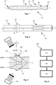
- Figure 1 schematically shows a side view of a tool 10 with a working section 12, a shaft 14, the shaft comprising a connection end 16 with a protruding structure 18 and grooves 20.
- the tool 10 has a longitudinal axis L.
- the shaft 14 and thus the connection end 16 may have hexagonal cross-sections. Their diameters may be more than 20 mm, in particular it may be between 25 and 35 mm, preferably 28 mm.
- the working section 12 and a striking end 22, located at a free end of the connection end 16, are through-hardened.
- the rest of the tool 10 is soft-hardened.
- the tool 10 contains several sections of different microstructure.
- FIG. 2 shows an enlarged side view of the connection end 16.
- the connection end 16 comprises six grooves 20.
- the grooves 20 are evenly and circumferentially distributed around the connection end 16.
- the protruding structure 18 has a ring structure. It surrounds the rest of the shaft 14 and thus protrudes radially from the rest of the shaft 14.
- Figure 3 shows a longitudinal cross-section according to the reference signs III of figure 2 and cut along a central plane comprising the longitudinal axis L.
- the surface of the protruding structure 18 comprises several sections with different radii of curvature R1, R2, R3, R4, and R5.
- the radii may, for example, be between 5 and 7 mm.
- the largest diameter of the protruding structure 18 may be between 40 and 45 mm, preferably 42.5 mm.
- the protruding structure 18 has a first half A and a second half B both being separated from each other by a plane perpendicular to the longitudinal axis L.
- the surface of the protruding structure 18 has a finite gradient along a direction parallel to longitudinal axis L.
- figure 3 shows an angle alpha between a tangent through a point P of the surface of the protruding structure 18 and the longitudinal axis L within the plane of the cross-section shown in figure 3 and thus along a direction parallel to the longitudinal axis L.
- the angle alpha is an acute angle and thus less than 90° in relation to the longitudinal axis L. The same applies for all other points along the surface within the first half A of the protruding section 18.
- the surface within the first half A and according to the cross-section shown in figure 3 is basically S-shaped.
- a ring-shaped spraying apparatus 24 By means of a ring-shaped spraying apparatus 24 it is thus possible to spray a coolant along a spraying direction S onto the surface of the tool 10 ( figure 1 ) and in particular onto the surface of the protruding structure 18.
- the spraying direction S is steeper relative to the longitudinal axis L than the steepest tangent of the surface within the first half A. Hence, the surface of the protruding structure 18 does not even partly shade itself along the spraying direction S.
- Figure 4 shows a flow chart of a method 100 for producing a tool 10, for example the tool 10 according to the embodiment as described in relation to figures 1 to 3 .
- a first step 110 the tool 10 is formed from a raw material.
- the protruding structure 18 may be welded onto a, basically rod-shaped, raw form of the shaft 14.
- the tool 10 is hardened:
- a second step 120 the tool 10 is inductively heated section by section along its longitudinal axis L by an inductive heating apparatus.
- a third step 130 which preferably may take place in parallel to the second step 120, at least one of the already heated sections is cooled by spraying a coolant along the direction S onto the surface of the section.
- the spraying apparatus 24 may preferably be used.
- the spraying apparatus 24 may be moved from one end of the tool 10, in particular the left end according to figure 3 , to its other end, thus for example its right end.
- the feed rate, the heating power and duration, the intensity of spraying and thus the cooling power, etc. may be changed from section to section.
- the tool 10 may be specifically hardened in each of the sections.
Abstract
Description
- The present invention relates to a tool, in particular a chisel, for a power tool, the tool having a longitudinal axis and comprising a working section and a shaft with a connection end for connecting the tool to a tool holder of the power tool, wherein the shaft comprises at least one protruding structure protruding from the shaft.
- Demolition works, for example breaking building elements made of concrete or the like, often place high demands on the tools, e. g. chisels, employed.
- Therefore, it is an object of the present invention to provide a tool according to the preamble of claim 1 having high robustness and great durability and a method for producing such a tool.
- This is achieved in a number of aspects of the present invention, in which a first aspect is a tool, in particular a chisel, for a power tool, the tool having a longitudinal axis and comprising a working section and a shaft with a connection end for connecting the tool to a tool holder of the power tool, wherein the shaft comprises at least one protruding structure protruding from the shaft, wherein at least within a first of two halves of the protruding structure, which are separated from each other by a plane perpendicular to the longitudinal axis, the surface of the protruding structure has a finite gradient along a direction parallel to the longitudinal axis.
- Hence, at least within the first half of the protruding structure neither the protruding structure as a whole nor a part of it project from the shaft at a perpendicular angle.
- In particular, the surface of the protruding structure may be formed such that there exists at least one angle in relation to the longitudinal axis, along which the surface of the protruding structure does not even partly shade itself.
- Thus, a basic idea behind the invention is that the protruding structure is formed such that its whole surface is accessible along at least one direction, the direction being non-perpendicular to the longitudinal axis. This allows to treat different sections of the tool differentially. For example, the tool may be hardened to different hardnesses depending on the respective section of the tool. Due to the specific surface of the protruding structure, the protruding structure does not stand in its own way during the treatment. Hence, the protruding structure and its surroundings as well as the rest of the tool may be treated in a well-controlled fashion.
- As a result, powerful treatments, for example efficient hardening methods, become applicable even to tools with such a protruding structure, providing robust tools with outstanding durability.
- The tool may be a chisel, in particular a pointed chisel or a flat chisel.
- The protruding structure may be part of the connection end. Preferably, at least the shaft and the protruding structure may be formed as one single body. For example, the protruding structure may be welded onto and around the shaft.
- In a preferred embodiment of the invention the protruding structure may be a ring structure. It may thus form a connection end of a tool for high power tools.
- The protruding structure may be asymmetrical to a center plane of the protruding structure, the center plane being perpendicular to the longitudinal axis.
- The protruding structure and in particular its surface may have two sides, one side facing towards the working section and the other side facing into the counter-direction, i. e. towards a free end of the connection end. At least one of the sides may have a S-shaped or at least a basically S-shaped form.
- A further aspect of the invention is that the tool may be hardened by inductive hardening. By way of inductive hardening, an applied heating power and a feed rate of the tool may be changed along the entire length of the tool, thus providing a simple way of treating the tool differentially in different sections. For example, in some sections the tool may be through-hardened and in some sections the tool may be shell-hardened.
- If the tool is, for example, a chisel, during chiseling, each section of the tool, i. e. the chisel, is subjected to different stresses. The different stresses require different microstructures or hardness profiles of the material of the tool in each of its sections. Hence, in a preferred embodiment of the invention the tool may contain at least two sections of different microstructure.
- Yet such a differentiation cannot or at least cannot easily be achieved by conventional heat treatments like furnace-based hardening treatments, whereas by induction hardening, heating power and feed rate can be changed along the entire length of the tool during hardening. Each of the sections may be adapted to the specific demands it is to face, e. g. during demolition works or the like.
- Particularly, the working section may be through-hardened. The working section of the chisel is usually subjected to abrasive stress during e. g. demolition works. Due to wear, the cross-section of the tool decreases continuously, so a through-hardened structure is required in order to prevent the chisel from getting blunt.
- Furthermore, at least a part of the shaft may be shell-hardened. In particular, the connection end or at least a part of the connection end may be shell-hardened. In order to protect its outer surface against external damage, the surface may be hardened to achieve a hard, wear-resistant layer. The thickness of the layer may be between 0.5 and 5 mm, preferably 2 mm. The central core of the connection end or at least of the part of the connection end may remain non-hardened and soft. The combination of the hardened surface and the soft core may provide a high toughness against bending and may, nevertheless, retain a sufficient abrasion resistance.
- Preferably, in particular in case the tool is a chisel or the like, an end-section of the connection end may be through-hardened in order to withstand, for example, strikes of a chiseling machine the tool is used with.
- A further aspect of the invention is that the connection end may have six grooves, which may preferentially be distributed evenly around the connection end. Furthermore, at least the shaft may have a hexagonal or at least basically hexagonal cross-section. These measures permit a safe mounting in a tool holder of the power tool and thus may further increase the durability of the tool.
- Another aspect of the invention is a method for producing a tool according to the invention one of the preceding claims, wherein the method comprises a first step of inductively heating the tool.
- The method may comprise a second step of cooling the tool by spraying a coolant along a direction along which the surface of the protruding structure of the tool does not even partly shade itself. This is possible due to the specific shape of the protruding structure. Thus, it is possible to heat one section of the tool and to cool another section of the tool at the same time.
- The invention will be described further, by way of example, with reference to the accompanying drawings which illustrate preferred embodiments thereof, it being understood that the following description is illustrative and not limitative of the scope of the invention. The features shown there are not necessarily to be understood to scale and are presented in such a way that the special features of the invention are clearly visible. The various features may be realized individually or in combination in any desired way in variants of the invention.
-
- Figure 1
- schematically shows a side view of a tool;
- Figure 2
- shows a side view of a connection end of the tool;
- Figure 3
- shows a longitudinal sectional view of a section of the connection end comprising a protruding structure; and
- Figure 4
- shows a flow chart of a method for producing a tool.
- Same reference signs are used for functionally equivalent elements in all figures.
-
Figure 1 schematically shows a side view of atool 10 with aworking section 12, ashaft 14, the shaft comprising aconnection end 16 with aprotruding structure 18 andgrooves 20. Thetool 10 has a longitudinal axis L. Theshaft 14 and thus theconnection end 16 may have hexagonal cross-sections. Their diameters may be more than 20 mm, in particular it may be between 25 and 35 mm, preferably 28 mm. - The working
section 12 and astriking end 22, located at a free end of theconnection end 16, are through-hardened. The rest of thetool 10 is soft-hardened. Thus, thetool 10 contains several sections of different microstructure. -
Figure 2 shows an enlarged side view of theconnection end 16. Theconnection end 16 comprises sixgrooves 20. Thegrooves 20 are evenly and circumferentially distributed around theconnection end 16. - The protruding
structure 18 has a ring structure. It surrounds the rest of theshaft 14 and thus protrudes radially from the rest of theshaft 14. -
Figure 3 shows a longitudinal cross-section according to the reference signs III offigure 2 and cut along a central plane comprising the longitudinal axis L. The surface of the protrudingstructure 18 comprises several sections with different radii of curvature R1, R2, R3, R4, and R5. The radii may, for example, be between 5 and 7 mm. The largest diameter of the protrudingstructure 18 may be between 40 and 45 mm, preferably 42.5 mm. - The protruding
structure 18 has a first half A and a second half B both being separated from each other by a plane perpendicular to the longitudinal axis L. - At least within the first half A the surface of the protruding
structure 18 has a finite gradient along a direction parallel to longitudinal axis L. As an example,figure 3 shows an angle alpha between a tangent through a point P of the surface of the protrudingstructure 18 and the longitudinal axis L within the plane of the cross-section shown infigure 3 and thus along a direction parallel to the longitudinal axis L. The angle alpha is an acute angle and thus less than 90° in relation to the longitudinal axis L. The same applies for all other points along the surface within the first half A of the protrudingsection 18. - The surface within the first half A and according to the cross-section shown in
figure 3 is basically S-shaped. - By means of a ring-shaped
spraying apparatus 24 it is thus possible to spray a coolant along a spraying direction S onto the surface of the tool 10 (figure 1 ) and in particular onto the surface of the protrudingstructure 18. The spraying direction S is steeper relative to the longitudinal axis L than the steepest tangent of the surface within the first half A. Hence, the surface of the protrudingstructure 18 does not even partly shade itself along the spraying direction S. - Hence, by moving the spraying
apparatus 24 in a direction parallel to the longitudinal axis L and from left to right according tofigure 3 , the whole surface of thetool 10 and in particular of the protrudingstructure 18 can be wetted by the coolant and thus be cooled in a well-controlled manner. -
Figure 4 shows a flow chart of amethod 100 for producing atool 10, for example thetool 10 according to the embodiment as described in relation tofigures 1 to 3 . - In a
first step 110 thetool 10 is formed from a raw material. For example, the protrudingstructure 18 may be welded onto a, basically rod-shaped, raw form of theshaft 14. - In the following steps, the
tool 10 is hardened:
In asecond step 120 thetool 10 is inductively heated section by section along its longitudinal axis L by an inductive heating apparatus. - In a
third step 130, which preferably may take place in parallel to thesecond step 120, at least one of the already heated sections is cooled by spraying a coolant along the direction S onto the surface of the section. - For this, the spraying
apparatus 24 may preferably be used. The sprayingapparatus 24 may be moved from one end of thetool 10, in particular the left end according tofigure 3 , to its other end, thus for example its right end. - The feed rate, the heating power and duration, the intensity of spraying and thus the cooling power, etc. may be changed from section to section. Thus, the
tool 10 may be specifically hardened in each of the sections.
Claims (11)
- Tool (10), in particular a chisel, for a power tool, the tool (10) having a longitudinal axis (L) and comprising a working section (12) and a shaft (14) with a connection end (16) for connecting the tool (10) to a tool holder of the power tool, wherein the shaft (14) comprises at least one protruding structure (18) protruding from the shaft (14), characterized in that at least within one of two halves (A, B) of the protruding structure (18) which are separated from each other by a plane perpendicular to the longitudinal axis (L), the surface of the protruding structure (18) has a finite gradient along a direction parallel to the longitudinal axis (L).
- Tool according to claim 1, characterized in that the protruding structure (18) is a ring structure.
- Tool according to one of the preceding claims, characterized in that the protruding structure (18) is asymmetrical to a center plane of the protruding structure, the center plane being perpendicular to the longitudinal axis (L).
- Tool according to one of the preceding claims, characterized in that the tool (10) is hardened by inductive hardening.
- Tool according to one of the preceding claims, characterized in that the tool (10) contains at least two sections of different microstructure.
- Tool according to one of the preceding claims, characterized in that the working section (12) is through-hardened.
- Tool according to one of the preceding claims, characterized in that at least a part of the shaft (14) is shell-hardened.
- Tool according to one of the preceding claims, characterized in that an end-section (22) of the connection end (16) is through-hardened.
- Tool according to one of the preceding claims, characterized in that the connection end (16) has six circumferentially evenly distributed grooves (20).
- Method (100) for producing a tool (10) according to one of the preceding claims, characterized in that the method (100) comprises a first step (110) of inductively heating the tool (10).
- Method according to the preceding claim, characterized in that it comprises a second step (120) of cooling the tool (10) by spraying a coolant along a direction (S) along which the surface of the protruding structure (18) of the tool (10) does not even partly shade itself.
Priority Applications (3)
| Application Number | Priority Date | Filing Date | Title |
|---|---|---|---|
| EP20186368.5A EP3939748A1 (en) | 2020-07-17 | 2020-07-17 | Tool with protruding structure |
| US18/014,648 US20230356378A1 (en) | 2020-07-17 | 2021-07-07 | Tool with protruding structure |
| PCT/EP2021/068764 WO2022013026A1 (en) | 2020-07-17 | 2021-07-07 | Tool with protruding structure |
Applications Claiming Priority (1)
| Application Number | Priority Date | Filing Date | Title |
|---|---|---|---|
| EP20186368.5A EP3939748A1 (en) | 2020-07-17 | 2020-07-17 | Tool with protruding structure |
Publications (1)
| Publication Number | Publication Date |
|---|---|
| EP3939748A1 true EP3939748A1 (en) | 2022-01-19 |
Family
ID=71670054
Family Applications (1)
| Application Number | Title | Priority Date | Filing Date |
|---|---|---|---|
| EP20186368.5A Pending EP3939748A1 (en) | 2020-07-17 | 2020-07-17 | Tool with protruding structure |
Country Status (3)
| Country | Link |
|---|---|
| US (1) | US20230356378A1 (en) |
| EP (1) | EP3939748A1 (en) |
| WO (1) | WO2022013026A1 (en) |
Citations (2)
| Publication number | Priority date | Publication date | Assignee | Title |
|---|---|---|---|---|
| US3655244A (en) * | 1970-07-30 | 1972-04-11 | Int Tool Sales | Impact driven tool with replaceable cutting point |
| DE19757271A1 (en) * | 1997-12-22 | 1999-06-24 | Hilti Ag | Tool |
-
2020
- 2020-07-17 EP EP20186368.5A patent/EP3939748A1/en active Pending
-
2021
- 2021-07-07 WO PCT/EP2021/068764 patent/WO2022013026A1/en active Application Filing
- 2021-07-07 US US18/014,648 patent/US20230356378A1/en active Pending
Patent Citations (2)
| Publication number | Priority date | Publication date | Assignee | Title |
|---|---|---|---|---|
| US3655244A (en) * | 1970-07-30 | 1972-04-11 | Int Tool Sales | Impact driven tool with replaceable cutting point |
| DE19757271A1 (en) * | 1997-12-22 | 1999-06-24 | Hilti Ag | Tool |
Also Published As
| Publication number | Publication date |
|---|---|
| WO2022013026A1 (en) | 2022-01-20 |
| US20230356378A1 (en) | 2023-11-09 |
Similar Documents
| Publication | Publication Date | Title |
|---|---|---|
| KR20070084136A (en) | Cutting tool for metal working and method for producing it | |
| EP3616842B1 (en) | Tool bit | |
| US20170072477A1 (en) | Partially hardened rotary tool and corresponding production method | |
| JP2000239744A (en) | Heat treatment method for hollow cylindrical work | |
| EP3939748A1 (en) | Tool with protruding structure | |
| CN112831638A (en) | High-precision metal surface composite strengthening processing method and device | |
| US10787795B2 (en) | Aggregate crushing tool | |
| CN110303305B (en) | Processing technique of outer ring | |
| US20080189930A1 (en) | Method for making a hammer | |
| CN114905235A (en) | Forging forming process for triple gear | |
| KR20030076396A (en) | Hollow steel hexagonal rod and induction hardening method thereof | |
| KR101606288B1 (en) | The heat treatment of steel rods heat striking a diamond or tungsten carbide rod into the notch on the wheel center for a bending wheel Notch inhibition multilayer electrodeposition method using the same wheel and notch | |
| RU2728198C1 (en) | Method of hardening of disk furrow opener cutting edge | |
| JP2003329048A (en) | Manufacturing method for bearing raceway member | |
| US6978852B2 (en) | Rock drill product and method | |
| EP4155031A1 (en) | Breaking tool, breaking hammer and method of maintaining shape of breaking tool | |
| RU2183681C1 (en) | Method for hardening working surfaces of disc cutter | |
| CN113329834A (en) | Application tool and method for producing an application tool | |
| JPH1161264A (en) | Crawler bush and its manufacture | |
| US11124866B2 (en) | Method of treating the surfaces of mould parts for casting moulds consisting of a steel material | |
| RU2716329C1 (en) | Method of hardening of hard-alloy tool | |
| US20230124502A1 (en) | Hammer bushings with softened outer region | |
| US20220412406A1 (en) | Hammer bushings with hardened inner region | |
| RU2137590C1 (en) | Hard-alloy tool strengthening method | |
| CN102703651A (en) | Manufacturing method for hydraulic system oil cylinder of concrete pump truck and product thereof |
Legal Events
| Date | Code | Title | Description |
|---|---|---|---|
| PUAI | Public reference made under article 153(3) epc to a published international application that has entered the european phase |
Free format text: ORIGINAL CODE: 0009012 |
|
| STAA | Information on the status of an ep patent application or granted ep patent |
Free format text: STATUS: THE APPLICATION HAS BEEN PUBLISHED |
|
| AK | Designated contracting states |
Kind code of ref document: A1 Designated state(s): AL AT BE BG CH CY CZ DE DK EE ES FI FR GB GR HR HU IE IS IT LI LT LU LV MC MK MT NL NO PL PT RO RS SE SI SK SM TR |
|
| STAA | Information on the status of an ep patent application or granted ep patent |
Free format text: STATUS: REQUEST FOR EXAMINATION WAS MADE |
|
| 17P | Request for examination filed |
Effective date: 20220719 |
|
| RBV | Designated contracting states (corrected) |
Designated state(s): AL AT BE BG CH CY CZ DE DK EE ES FI FR GB GR HR HU IE IS IT LI LT LU LV MC MK MT NL NO PL PT RO RS SE SI SK SM TR |