EP3939725A1 - Insert and cutting tool - Google Patents
Insert and cutting tool Download PDFInfo
- Publication number
- EP3939725A1 EP3939725A1 EP20769719.4A EP20769719A EP3939725A1 EP 3939725 A1 EP3939725 A1 EP 3939725A1 EP 20769719 A EP20769719 A EP 20769719A EP 3939725 A1 EP3939725 A1 EP 3939725A1
- Authority
- EP
- European Patent Office
- Prior art keywords
- grooves
- insert
- end part
- away
- width
- Prior art date
- Legal status (The legal status is an assumption and is not a legal conclusion. Google has not performed a legal analysis and makes no representation as to the accuracy of the status listed.)
- Granted
Links
Images




Classifications
-
- B—PERFORMING OPERATIONS; TRANSPORTING
- B23—MACHINE TOOLS; METAL-WORKING NOT OTHERWISE PROVIDED FOR
- B23B—TURNING; BORING
- B23B27/00—Tools for turning or boring machines; Tools of a similar kind in general; Accessories therefor
- B23B27/14—Cutting tools of which the bits or tips or cutting inserts are of special material
- B23B27/141—Specially shaped plate-like cutting inserts, i.e. length greater or equal to width, width greater than or equal to thickness
- B23B27/145—Specially shaped plate-like cutting inserts, i.e. length greater or equal to width, width greater than or equal to thickness characterised by having a special shape
-
- B—PERFORMING OPERATIONS; TRANSPORTING
- B23—MACHINE TOOLS; METAL-WORKING NOT OTHERWISE PROVIDED FOR
- B23B—TURNING; BORING
- B23B27/00—Tools for turning or boring machines; Tools of a similar kind in general; Accessories therefor
- B23B27/14—Cutting tools of which the bits or tips or cutting inserts are of special material
- B23B27/16—Cutting tools of which the bits or tips or cutting inserts are of special material with exchangeable cutting bits or cutting inserts, e.g. able to be clamped
- B23B27/1603—Cutting tools of which the bits or tips or cutting inserts are of special material with exchangeable cutting bits or cutting inserts, e.g. able to be clamped with specially shaped plate-like exchangeable cutting inserts, e.g. chip-breaking groove
- B23B27/1611—Cutting tools of which the bits or tips or cutting inserts are of special material with exchangeable cutting bits or cutting inserts, e.g. able to be clamped with specially shaped plate-like exchangeable cutting inserts, e.g. chip-breaking groove characterised by having a special shape
-
- B—PERFORMING OPERATIONS; TRANSPORTING
- B23—MACHINE TOOLS; METAL-WORKING NOT OTHERWISE PROVIDED FOR
- B23B—TURNING; BORING
- B23B27/00—Tools for turning or boring machines; Tools of a similar kind in general; Accessories therefor
- B23B27/10—Cutting tools with special provision for cooling
-
- B—PERFORMING OPERATIONS; TRANSPORTING
- B23—MACHINE TOOLS; METAL-WORKING NOT OTHERWISE PROVIDED FOR
- B23B—TURNING; BORING
- B23B2200/00—Details of cutting inserts
- B23B2200/08—Rake or top surfaces
- B23B2200/086—Rake or top surfaces with one or more grooves
Definitions
- the present disclosure relates to an insert and a cutting tool.
- Cemented carbide, cermet and ceramics are materials excellent in heat resistance and wear resistance, and are therefore used as an insert for a cutting tool.
- the insert is brought into contact with a workpiece in use at high speed, and the insert is therefore subjected to temperature rise.
- the insert and the workpiece are cooled with a coolant during a machining process.
- a plurality of grooves that serve as a flow path for the coolant are disposed on a rake surface of the insert in
- Patent Document 1 is a diagrammatic representation of Patent Document 1
- Patent Document 1 Japanese Patent No. 5843102
- An insert of the present disclosure includes a base.
- the base includes a first surface, a second surface connecting to the first surface, and a cutting edge located on at least a part of a ridgeline of the first surface and the second surface.
- the first surface includes a plurality of grooves located at a position away from the ridgeline and at an angle of 20-90° relative to the ridgeline.
- the grooves are extended from a first end part being an end part closest to the cutting edge to a second end part being an end part most away from the cutting edge.
- the grooves are away from the ridgeline in a range of 40-700 ⁇ m.
- a width W of the grooves is 50-700 ⁇ m, and a depth D of the grooves is 20-700 ⁇ m.
- a cutting tool of the present disclosure includes a holder, which has a length extending from a first end to a second end and includes a pocket located on a side of the first end, and the insert located in the pocket.
- Inserts in the present disclosure are described in detail below with reference to the drawings.
- the drawings referred to in the following illustrate, in simplified form, only main members necessary for describing the embodiments.
- the inserts may include any arbitrary structural member not illustrated in the drawings referred to.
- Dimensions of the members in each of the drawings faithfully represent neither dimensions of actual structural members nor dimensional ratios of these members.
- the insert 1 illustrated in FIG. 1 is an embodiment of an indexable cutting insert used by being attached to a predetermined position at a front end of a holder (not illustrated).
- the insert 1 includes a base 3 composed of cemented carbide, cermet, or the like.
- the insert 1 may include the base 3 composed of a so-called cemented carbide including WC, and Co, Ni and Fe used for a binding phase.
- the use of the base 3 leads to excellent welding resistance with respect to metal including Ti.
- WC denotes WC particles.
- the WC particles may have, for example, a mean particle diameter of 0.5-1.5 ⁇ m.
- the binding phase may be an iron group metal, such as Ni and Co.
- the base 3 may include 4-12 mass% of the binding phase.
- the base 3 may include only WC as a rest, besides the binding phase.
- a range, such as 4-12 mass% denotes being a lower limit value or more and an upper limit value or less.
- the insert 1 has a polygonal plate shape, and includes a first surface 5 and a second surface 7 connecting to the first surface 5.
- the insert 1 also includes a cutting edge 9 located on at least a part of a ridgeline 8 of the first surface 5 and the second surface 7.
- the first surface 5 corresponds to a rake surface 5, and the second surface 7 corresponds to a flank surface 7 in FIG. 1 .
- the first surface 5 may include a through hole 19 that penetrates the insert 1 vertically in order to fix the insert 1 to the holder described below.
- the cutting edge 9 may be located on at least a part of the ridgeline 8 in the insert 1. Specifically, the cutting edge 9 may be located on portions corresponding to two sides, or may be located in a ring shape on the whole of an outer peripheral part of the first surface 5.
- Dimensions of the insert 1 are not particularly limited. For example, a length of one side of the first surface 5 is settable to approximately 5-20 mm, and a height between the first surface 5 and a surface (lower surface) located on a side opposite to the first surface 5 is settable to approximately 3-20 mm.
- the insert 1 of the present disclosure includes a plurality of grooves 11 at a position away from the ridgeline 8 on the first surface 5 as in the top view of FIG. 2 .
- the grooves 11 are extended from a first end part 12a that is an end part being closest to the ridgeline 8 toward a second end part 12b that is an end part most away from the cutting edge 9.
- These grooves 11 are located at an angle ⁇ 1 of 20-90° relative to the ridgeline 8.
- the angle relative to the ridgeline 8 of the grooves 11 denotes a smaller angle from among angles at which an extending direction of the grooves 11 intersects with the cutting edge 9.
- at least one of the grooves 11 may be located at the angle of 20-90° relative to the cutting edge 9. That is, all of the grooves 11 need not satisfy the above relationship.
- the above angle of the grooves 11 located at a corner part 14 may be 90°.
- a groove 11-1 in FIG. 2 is disposed at an angle of approximately 45° relative to the cutting edge 9.
- the grooves 11 are away from the ridgeline 8 in a range of 40-700 ⁇ m. In other words, the distance between the grooves 11 and the ridgeline 8 is 40-700 ⁇ m. That is, the grooves 11 are not connected to the ridgeline 8.
- the cutting edge 9 is less prone to fracture if the distance between the grooves 11 and the ridgeline 8 is set to 40 ⁇ m or more. Cutting force can be lowered if the distance between the grooves 11 and the ridgeline 8 is set to 700 ⁇ m or less.
- the distance between the grooves 11 and the ridgeline 8 may be set to 50-120 ⁇ m. With this configuration, the cutting edge 11 of the insert 1 is less prone to fracture and the cutting force is low.
- the distance between the grooves 11 and the ridgeline 8 may be obtained by measuring a minimum distance between one groove 11 and the ridgeline 8.
- the insert 1 of the present disclosure may include one in which one of the grooves 11 is connected to the ridgeline 8.
- FIG. 3 is an enlarged view of a neighborhood of the cutting edge 9 if the first surface 5 is viewed from above.
- the grooves 11 are located at the angle of 90° relative to the ridgeline 8 in an embodiment of FIG. 3 .
- a width of the grooves 11 located on the surface of the first surface 5 is 50-700 ⁇ m.
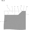
- FIG. 4 is a cross section of the insert 1 which is vertical to the surface of the first surface 5 in the neighborhood of the ridgeline 8 that is the cutting edge 9.
- the groove 11 includes a bottom surface 11a and an opening 13. It also includes a raised surface 11b that connects to the bottom surface 11a on a side of the first end part 12a of the groove 11.
- a depth D of the groove 11 illustrated in FIG. 4 (refer to FIG. 4 with regard to "D", and the depth is a length in a depth direction in FIG. 3 ) is 20-700 ⁇ m.
- the spacing S between the grooves 11 adjacent to each other illustrated in FIG. 3 is 50-700 ⁇ m.
- An average value of the widths W of the grooves 11 and an average value of the depths D of the grooves 11 may fall within the above range.
- the insert 1 of the present disclosure has low cutting force and has excellent fracture resistance, by having the above configuration.
- the insert 1 of the present disclosure is capable of carrying out a high-speed machining process because of being excellent in cooling effect.
- the insert 1 including the grooves 11 thus configured, friction between the rake surface 5 and chips of the workpiece is low, resulting in low cutting force. Additionally, the cutting edge 9 has excellent fracture resistance because the grooves 11 do not reach the ridgeline 8.
- the grooves 11 serve as a micro channel for the coolant if the coolant is supplied toward the cutting edge 9, and it is therefore possible to carry out a high-speed machining.
- the width W of the grooves 11 may be 50-200 ⁇ m.
- the depth D of the grooves 11 may be 50-200 ⁇ m.
- the spacing S between the grooves 11 adjacent to each other may be 50-200 ⁇ m.
- the raised surface 11b is located on a side of the first end part 12a of the groove 11, whereas no raised surface may be located on a side of the second end part 12b of the groove 11.
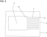
- the groove 11 may be connected to, for example, other space, such as a concave part 15, in the second end part 12b, and the second end part 12b in the groove 11 may be opened as illustrated in FIG. 5 .
- a coating layer including a TiCN layer (not illustrated) or an Al 2 O 3 layer (not illustrated) may be disposed on a surface of the base 3 in the insert 1 of the present disclosure.
- the base 3 may be exposed on at least a first region 17 which is in the neighborhood of the cutting edge 9 and the grooves 11 on the first surface 5 in the insert 1 of the present disclosure.
- the coating layer may not be present on the surface of the base 3 in the neighborhood of the cutting edge 9 and the grooves 11 on the rake surface 5.
- the first region 17 denotes a region located within 0.5 mm from the cutting edge 9 and the grooves 11.
- the coating layer may not be present on the entire surface of the base 3.
- a ratio (S/W) of the spacing S of the grooves 11 adjacent to each other to the width W of the grooves 11 may be 0.9-2.0 in the insert 1 of the present disclosure. With this configuration, the insert 1 has an excellent balance between friction resistance and cooling effect.
- a ratio (D/W) of the depth D of the grooves 11 to the width W of the grooves 11 may be 0.5-2.0.
- the width W of the grooves 11 in the present disclosure denotes an average value of the widths W of the grooves 11. That is, if the grooves 11 have approximately the same width W from the first end part 12a to the second end part 12b as illustrated in FIG. 6(a) , the grooves 11 are divided into five in the extending direction thereof, and the average value of the widths W of the grooves 11 in a region M1 having a length of 20-80% as viewed from the first end part 12a is obtained.
- the grooves 11 are changed at an approximately constant rate from the first end part 12a to the second end part 12b as illustrated in FIG. 6(b) , the grooves 11 are divided into five in the extending direction thereof, and an average value of the widths W of the grooves 11 in a region M2 having a length of 20-60% as viewed from the first end part 12a is obtained.
- the depths D of the grooves 11 and the spacings S of the grooves 11 adjacent to each other may be measured according to similar standards.
- the reason for measuring the W in the regions of the grooves 11 which are located near the first end part 12a is that the insert 1 of the present disclosure is capable of producing operational effects as long as the widths W of the grooves 11 in the region near the cutting edge 9 fall within the range set to the insert 1 of the present disclosure.
- W1 indicates a width of the groove 11 at a position located 0.5 mm away from the first end part 12a
- W2 indicates a width of the groove 11 at a position located 2.0 mm away from the first end part 12a. It may be preferable to set to W1 ⁇ W2. With this configuration, the width of the groove 11 becomes small in the vicinity of the first end part 12a, and the coolant is therefore likely to be discharged vigorously from the groove 11.
- D1 indicates a depth of the groove 11 at a position located 0.5 mm away from the first end part 12a
- D2 indicates a depth of the groove 11 at a position located 2.0 mm away from the first end part 12a. It may be preferable to set to D1 ⁇ D2. With this configuration, the depth of the groove 11 becomes small in the vicinity of the first end part 12a, and the coolant is therefore likely to be discharged vigorously from the groove 11.
- the groove 11 may satisfy a relationship of (D2/D1)>(W2/W1). With this configuration, a change in the depth D of the groove 11 is larger than a change in the width W of the groove 11, and the coolant is therefore likely to be discharged vigorously from the groove 11.
- a shape of the groove 11 (hereinafter also referred to as a cross-sectional shape of the groove 11) in a cross section of the base 3 which intersects at right angles in the extending direction of the groove 11 may be a shape in which a width of the opening 13 is larger than a width of the bottom surface 11a, such as a semicircular shape, a triangular shape, or a trapezoidal shape.
- the grooves 11 may be formed on the rake surface 5 so as to serve as the grooves 11 in the insert 1 of the present disclosure, for example, by drilling or using a laser beam.
- the insert 1 is also obtainable by manufacturing a molded body including concave parts that serve as the grooves 11 after sintering by using a mold including convex parts corresponding to the grooves 11, followed by sintering the molded body.
- the cutting tool 101 of the present disclosure is, for example, a bar-shaped body extended from a first end (an upper end in FIG. 9 ) to a second end (a lower end in FIG. 9 ) as illustrated in FIG. 9 .
- the cutting tool 101 includes a holder 105 which has a length from the first end (front end) to the second end, and which includes a pocket 103 located on a side of the first end, and the insert 1 located in the pocket 103 as illustrated in FIG. 9 .
- the cutting tool 101 includes the insert 1 and is therefore capable of performing a stable machining process for a long term.
- the grooves 11 are omitted in FIG. 9 .
- the pocket 103 is a part which permits attachment of the insert 1 and which includes a seating surface parallel to a lower surface of the holder 105, and a constraining lateral surface vertical or inclined relative to the seating surface.
- the pocket 103 opens on a side of the first end of the holder 105.
- the insert 1 is located in the pocket 103.
- the lower surface of the insert 1 may be directly in contact with the pocket 103.
- a sheet (not illustrated) may be held between the insert 1 and the pocket 103.
- the insert 1 is attached to the holder 105 in the following manner. That is, at least a part of the ridgeline 8 where the first surface 5 being the rake surface 5 intersects with the second surface 7 being the flank surface 7 which is used as the cutting edge 9 is protruded outward from the holder 105.
- the insert 1 is attached to the holder 105 by a screw 107 in the present embodiment. Specifically, the insert 1 is attached to the holder 105 by inserting the screw 107 into the through hole 19 of the insert 1, and by inserting a front end of the screw 107 into a screw hole (not illustrated) formed in the pocket 103 so as to engage screw parts each other.
- the cutting tool 101 of the present disclosure may include a hose (not illustrated) whose front end includes a nozzle in order to supply a coolant to the cutting edge 9.
- a pump for supplying the coolant is connected to the hose.
- the holder 105 may include the nozzle 120 for supplying the coolant to the cutting edge 9 in the cutting tool 101 of the present disclosure as illustrated in FIG. 10 .
- a spout of the nozzle 120 located near the insert 1 facilitates the supply of the coolant to the cutting edge 9.
- the nozzle 120 may be fixed to a part of the holder 105.
- the holder 105 may include a hole used as the nozzle 120 as illustrated in FIG. 10 .
- the coolant discharged from the nozzle 120 may be, for example, an aqueous coolant or oil based coolant.
- the nozzle 120 may be connected to the pump (not illustrated) so as to carry out a discharge at a pressure of 0.5-20 MPa. Particularly, a higher-speed machining is achievable at a pressure of 10 MPa or more.
- steel and cast iron are usable as a material of the holder 105.
- steel having enhanced toughness may be used.
- the cutting tool for use in a so-called turning process is illustrated in the embodiment.
- Examples of the turning process include internal process, external process and grooving process.
- the cutting tool is not limited to ones which are used for the turning process.
- the insert 1 of the above embodiment may be used as a cutting tool used for milling process.
- the inserts of the present disclosure include a base composed of cemented carbide including WC and a binding phase.
- a workpiece Ti-6Al-4V was cut out to examine a relationship between the shape of the groove and the life of the insert, as well as a relationship between pressure of a coolant discharged from the nozzle and the life of the insert.
- Table 1 presents the presence/absence of groove, the shape of groove, the kind of the insert used, coolant pressure, and evaluation of machining.
- a relation between groove and cutting edge corresponds to a shape in which the grooves are extended toward a corner part as illustrated in FIGs. 1 and 2 .
- the inserts and the cutting tools each having the configuration of the present disclosure had a long life.
- the relationship between coolant pressure and cutting distance was examined on Sample No. 2 in Table 1. The results indicated that the cutting distance became longer with increasing the coolant pressure. There was a slight change in cutting distance if the coolant pressure was 10 MPa or more.
Landscapes
- Engineering & Computer Science (AREA)
- Mechanical Engineering (AREA)
- Milling Processes (AREA)
- Cutting Tools, Boring Holders, And Turrets (AREA)
Abstract
Description
- The present disclosure relates to an insert and a cutting tool.
- Cemented carbide, cermet and ceramics are materials excellent in heat resistance and wear resistance, and are therefore used as an insert for a cutting tool. The insert is brought into contact with a workpiece in use at high speed, and the insert is therefore subjected to temperature rise.
- For that reason, the insert and the workpiece are cooled with a coolant during a machining process. In order to enhance cooling effect thus obtained, a plurality of grooves that serve as a flow path for the coolant are disposed on a rake surface of the insert in
- Patent Document 1:
Japanese Patent No. 5843102 - An insert of the present disclosure includes a base. The base includes a first surface, a second surface connecting to the first surface, and a cutting edge located on at least a part of a ridgeline of the first surface and the second surface. The first surface includes a plurality of grooves located at a position away from the ridgeline and at an angle of 20-90° relative to the ridgeline. The grooves are extended from a first end part being an end part closest to the cutting edge to a second end part being an end part most away from the cutting edge. The grooves are away from the ridgeline in a range of 40-700 µm. A width W of the grooves is 50-700 µm, and a depth D of the grooves is 20-700 µm. Spacing S between the grooves adjacent to each other is 50-700 µm. A cutting tool of the present disclosure includes a holder, which has a length extending from a first end to a second end and includes a pocket located on a side of the first end, and the insert located in the pocket.
-
-
FIG. 1 is a perspective view illustrating an embodiment of inserts in the present disclosure; -
FIG. 2 is a top view illustrating an embodiment of the inserts in the present disclosure; -
FIG. 3 is an enlarged view of main parts on an upper surface illustrating an embodiment of the inserts in the present disclosure; -
FIG. 4 is a sectional view of main parts illustrating an embodiment of the inserts in the present disclosure; -
FIG. 5 is an enlarged view of main parts on an upper surface illustrating an embodiment of the inserts in the present disclosure; -
FIG. 6 is a schematic diagram illustrating an embodiment of the grooves of the inserts in the present disclosure; -
FIG. 7 is an enlarged view of main parts illustrating an embodiment of the inserts in the present disclosure; -
FIG. 8 is a sectional view of main parts illustrating an embodiment of the inserts in the present disclosure; -
FIG. 9 is a plan view illustrating an embodiment of cutting tools in the present disclosure; and -
FIG. 10 is a plan view illustrating an embodiment of cutting tools in the present disclosure. - Inserts in the present disclosure are described in detail below with reference to the drawings. For the sake of description, the drawings referred to in the following illustrate, in simplified form, only main members necessary for describing the embodiments. Hence, the inserts may include any arbitrary structural member not illustrated in the drawings referred to. Dimensions of the members in each of the drawings faithfully represent neither dimensions of actual structural members nor dimensional ratios of these members.
- The
insert 1 illustrated inFIG. 1 is an embodiment of an indexable cutting insert used by being attached to a predetermined position at a front end of a holder (not illustrated). Theinsert 1 includes abase 3 composed of cemented carbide, cermet, or the like. Theinsert 1 may include thebase 3 composed of a so-called cemented carbide including WC, and Co, Ni and Fe used for a binding phase. The use of thebase 3 leads to excellent welding resistance with respect to metal including Ti. - As used herein, "WC" denotes WC particles. The WC particles may have, for example, a mean particle diameter of 0.5-1.5 µm. The binding phase may be an iron group metal, such as Ni and Co. The
base 3 may include 4-12 mass% of the binding phase. Thebase 3 may include only WC as a rest, besides the binding phase. In the present disclosure, a range, such as 4-12 mass%, denotes being a lower limit value or more and an upper limit value or less. - The
insert 1 has a polygonal plate shape, and includes afirst surface 5 and asecond surface 7 connecting to thefirst surface 5. Theinsert 1 also includes acutting edge 9 located on at least a part of aridgeline 8 of thefirst surface 5 and thesecond surface 7. Thefirst surface 5 corresponds to arake surface 5, and thesecond surface 7 corresponds to aflank surface 7 inFIG. 1 . These are also true for the following drawings. Thefirst surface 5 may include a throughhole 19 that penetrates theinsert 1 vertically in order to fix theinsert 1 to the holder described below. Thecutting edge 9 may be located on at least a part of theridgeline 8 in theinsert 1. Specifically, thecutting edge 9 may be located on portions corresponding to two sides, or may be located in a ring shape on the whole of an outer peripheral part of thefirst surface 5. - Dimensions of the
insert 1 are not particularly limited. For example, a length of one side of thefirst surface 5 is settable to approximately 5-20 mm, and a height between thefirst surface 5 and a surface (lower surface) located on a side opposite to thefirst surface 5 is settable to approximately 3-20 mm. - The
insert 1 of the present disclosure includes a plurality ofgrooves 11 at a position away from theridgeline 8 on thefirst surface 5 as in the top view ofFIG. 2 . Thegrooves 11 are extended from afirst end part 12a that is an end part being closest to theridgeline 8 toward asecond end part 12b that is an end part most away from thecutting edge 9. Thesegrooves 11 are located at an angle θ1 of 20-90° relative to theridgeline 8. As used herein, the angle relative to theridgeline 8 of thegrooves 11 denotes a smaller angle from among angles at which an extending direction of thegrooves 11 intersects with thecutting edge 9. Among a plurality ofgrooves 11, at least one of thegrooves 11 may be located at the angle of 20-90° relative to thecutting edge 9. That is, all of thegrooves 11 need not satisfy the above relationship. - By setting the angle to 20-90°, chips are less likely to stay in the
grooves 11, and the chips tend to be discharged along thegrooves 11. Of thecutting edge 9, the above angle of thegrooves 11 located at acorner part 14 may be 90°. - A groove 11-1 in
FIG. 2 is disposed at an angle of approximately 45° relative to thecutting edge 9. - The
grooves 11 are away from theridgeline 8 in a range of 40-700 µm. In other words, the distance between thegrooves 11 and theridgeline 8 is 40-700 µm. That is, thegrooves 11 are not connected to theridgeline 8. Thecutting edge 9 is less prone to fracture if the distance between thegrooves 11 and theridgeline 8 is set to 40 µm or more. Cutting force can be lowered if the distance between thegrooves 11 and theridgeline 8 is set to 700 µm or less. - The distance between the
grooves 11 and theridgeline 8 may be set to 50-120 µm. With this configuration, thecutting edge 11 of theinsert 1 is less prone to fracture and the cutting force is low. - The distance between the
grooves 11 and theridgeline 8 may be obtained by measuring a minimum distance between onegroove 11 and theridgeline 8. Theinsert 1 of the present disclosure may include one in which one of thegrooves 11 is connected to theridgeline 8. -
FIG. 3 is an enlarged view of a neighborhood of thecutting edge 9 if thefirst surface 5 is viewed from above. Thegrooves 11 are located at the angle of 90° relative to theridgeline 8 in an embodiment ofFIG. 3 . A width of thegrooves 11 located on the surface of thefirst surface 5 is 50-700 µm. -
FIG. 4 is a cross section of theinsert 1 which is vertical to the surface of thefirst surface 5 in the neighborhood of theridgeline 8 that is thecutting edge 9. Thegroove 11 includes abottom surface 11a and anopening 13. It also includes a raisedsurface 11b that connects to thebottom surface 11a on a side of thefirst end part 12a of thegroove 11. A depth D of thegroove 11 illustrated inFIG. 4 (refer toFIG. 4 with regard to "D", and the depth is a length in a depth direction inFIG. 3 ) is 20-700 µm. The spacing S between thegrooves 11 adjacent to each other illustrated inFIG. 3 is 50-700 µm. An average value of the widths W of thegrooves 11 and an average value of the depths D of thegrooves 11 may fall within the above range. - The
insert 1 of the present disclosure has low cutting force and has excellent fracture resistance, by having the above configuration. Theinsert 1 of the present disclosure is capable of carrying out a high-speed machining process because of being excellent in cooling effect. - Specifically, with the
insert 1 including thegrooves 11 thus configured, friction between therake surface 5 and chips of the workpiece is low, resulting in low cutting force. Additionally, thecutting edge 9 has excellent fracture resistance because thegrooves 11 do not reach theridgeline 8. Thegrooves 11 serve as a micro channel for the coolant if the coolant is supplied toward thecutting edge 9, and it is therefore possible to carry out a high-speed machining. - The width W of the
grooves 11 may be 50-200 µm. The depth D of thegrooves 11 may be 50-200 µm. The spacing S between thegrooves 11 adjacent to each other may be 50-200 µm. - The raised
surface 11b is located on a side of thefirst end part 12a of thegroove 11, whereas no raised surface may be located on a side of thesecond end part 12b of thegroove 11. For example, thegroove 11 may be connected to, for example, other space, such as aconcave part 15, in thesecond end part 12b, and thesecond end part 12b in thegroove 11 may be opened as illustrated inFIG. 5 . - For example, a coating layer (not illustrated) including a TiCN layer (not illustrated) or an Al2O3 layer (not illustrated) may be disposed on a surface of the
base 3 in theinsert 1 of the present disclosure. Thebase 3 may be exposed on at least afirst region 17 which is in the neighborhood of thecutting edge 9 and thegrooves 11 on thefirst surface 5 in theinsert 1 of the present disclosure. In other words, the coating layer may not be present on the surface of thebase 3 in the neighborhood of thecutting edge 9 and thegrooves 11 on therake surface 5. As used herein, thefirst region 17 denotes a region located within 0.5 mm from thecutting edge 9 and thegrooves 11. Alternatively, the coating layer may not be present on the entire surface of thebase 3. - With this configuration, it is possible to prevent the workpiece from being welded to the
insert 1 even in the case of machining metal including, for example, titanium having high welding performance. - A ratio (S/W) of the spacing S of the
grooves 11 adjacent to each other to the width W of thegrooves 11 may be 0.9-2.0 in theinsert 1 of the present disclosure. With this configuration, theinsert 1 has an excellent balance between friction resistance and cooling effect. - A ratio (D/W) of the depth D of the
grooves 11 to the width W of thegrooves 11 may be 0.5-2.0. With this configuration, theinsert 1 has an excellent balance between friction resistance and cooling effect. Chips are less likely be caught in thegrooves 11, thereby making it easier to maintain performance of theinsert 1. - As used herein, the width W of the
grooves 11 in the present disclosure denotes an average value of the widths W of thegrooves 11. That is, if thegrooves 11 have approximately the same width W from thefirst end part 12a to thesecond end part 12b as illustrated inFIG. 6(a) , thegrooves 11 are divided into five in the extending direction thereof, and the average value of the widths W of thegrooves 11 in a region M1 having a length of 20-80% as viewed from thefirst end part 12a is obtained. - If the widths of the
grooves 11 are changed at an approximately constant rate from thefirst end part 12a to thesecond end part 12b as illustrated inFIG. 6(b) , thegrooves 11 are divided into five in the extending direction thereof, and an average value of the widths W of thegrooves 11 in a region M2 having a length of 20-60% as viewed from thefirst end part 12a is obtained. - The depths D of the
grooves 11 and the spacings S of thegrooves 11 adjacent to each other may be measured according to similar standards. The reason for measuring the W in the regions of thegrooves 11 which are located near thefirst end part 12a is that theinsert 1 of the present disclosure is capable of producing operational effects as long as the widths W of thegrooves 11 in the region near thecutting edge 9 fall within the range set to theinsert 1 of the present disclosure. - As illustrated in
FIG. 7 , W1 indicates a width of thegroove 11 at a position located 0.5 mm away from thefirst end part 12a, and W2 indicates a width of thegroove 11 at a position located 2.0 mm away from thefirst end part 12a. It may be preferable to set to W1<W2. With this configuration, the width of thegroove 11 becomes small in the vicinity of thefirst end part 12a, and the coolant is therefore likely to be discharged vigorously from thegroove 11. - As illustrated in
FIG. 8 , D1 indicates a depth of thegroove 11 at a position located 0.5 mm away from thefirst end part 12a, and D2 indicates a depth of thegroove 11 at a position located 2.0 mm away from thefirst end part 12a. It may be preferable to set to D1<D2. With this configuration, the depth of thegroove 11 becomes small in the vicinity of thefirst end part 12a, and the coolant is therefore likely to be discharged vigorously from thegroove 11. - The
groove 11 may satisfy a relationship of (D2/D1)>(W2/W1). With this configuration, a change in the depth D of thegroove 11 is larger than a change in the width W of thegroove 11, and the coolant is therefore likely to be discharged vigorously from thegroove 11. - A shape of the groove 11 (hereinafter also referred to as a cross-sectional shape of the groove 11) in a cross section of the
base 3 which intersects at right angles in the extending direction of thegroove 11 may be a shape in which a width of theopening 13 is larger than a width of thebottom surface 11a, such as a semicircular shape, a triangular shape, or a trapezoidal shape. - For example, after manufacturing cemented carbide in the shape of the insert including no
grooves 11 in theinsert 1 havingsuch grooves 11 on therake surface 5, thegrooves 11 may be formed on therake surface 5 so as to serve as thegrooves 11 in theinsert 1 of the present disclosure, for example, by drilling or using a laser beam. Alternatively, theinsert 1 is also obtainable by manufacturing a molded body including concave parts that serve as thegrooves 11 after sintering by using a mold including convex parts corresponding to thegrooves 11, followed by sintering the molded body. - It is possible to measure the shape of the
grooves 11 by using, for example, a shape analysis laser microscope. The measuring is made using VK-X1000 manufactured by KEYENCE CORPORATION in the present disclosure. Measurement conditions are as follows. Measurement mode: Simple measurement - Scanning mode: Focus variation
- Measurement size: Standard
- Pitch: 4.50 µm
- Brightness: 70
- To enable noise region processing: ON
- Coaxial vertical: 100
- Ring illumination: OFF
- Z-axis mode: Recommended setting
- Z measurement distance fixing: OFF
- Automatic upper and lower limits: ON
- Head: R
- Objective lens name: Plan
- Objective lens magnification: 10×
- NA: 0.3
- WD: 16.5 mm
- Brightness mode: Automatic
- Brightness (automatic): 70
- Brightness (manual): 2
- Edge enhancement: 5
- Cutting tools of the present disclosure are described below with reference to the drawings.
- The
cutting tool 101 of the present disclosure is, for example, a bar-shaped body extended from a first end (an upper end inFIG. 9 ) to a second end (a lower end inFIG. 9 ) as illustrated inFIG. 9 . - The
cutting tool 101 includes aholder 105 which has a length from the first end (front end) to the second end, and which includes apocket 103 located on a side of the first end, and theinsert 1 located in thepocket 103 as illustrated inFIG. 9 . Thecutting tool 101 includes theinsert 1 and is therefore capable of performing a stable machining process for a long term. Thegrooves 11 are omitted inFIG. 9 . - The
pocket 103 is a part which permits attachment of theinsert 1 and which includes a seating surface parallel to a lower surface of theholder 105, and a constraining lateral surface vertical or inclined relative to the seating surface. Thepocket 103 opens on a side of the first end of theholder 105. - The
insert 1 is located in thepocket 103. The lower surface of theinsert 1 may be directly in contact with thepocket 103. Alternatively, a sheet (not illustrated) may be held between theinsert 1 and thepocket 103. - The
insert 1 is attached to theholder 105 in the following manner. That is, at least a part of theridgeline 8 where thefirst surface 5 being therake surface 5 intersects with thesecond surface 7 being theflank surface 7 which is used as thecutting edge 9 is protruded outward from theholder 105. Theinsert 1 is attached to theholder 105 by ascrew 107 in the present embodiment. Specifically, theinsert 1 is attached to theholder 105 by inserting thescrew 107 into the throughhole 19 of theinsert 1, and by inserting a front end of thescrew 107 into a screw hole (not illustrated) formed in thepocket 103 so as to engage screw parts each other. - The
cutting tool 101 of the present disclosure may include a hose (not illustrated) whose front end includes a nozzle in order to supply a coolant to thecutting edge 9. A pump for supplying the coolant is connected to the hose. - The
holder 105 may include thenozzle 120 for supplying the coolant to thecutting edge 9 in thecutting tool 101 of the present disclosure as illustrated inFIG. 10 . A spout of thenozzle 120 located near theinsert 1 facilitates the supply of the coolant to thecutting edge 9. Thenozzle 120 may be fixed to a part of theholder 105. Alternatively, theholder 105 may include a hole used as thenozzle 120 as illustrated inFIG. 10 . The coolant discharged from thenozzle 120 may be, for example, an aqueous coolant or oil based coolant. - The
nozzle 120 may be connected to the pump (not illustrated) so as to carry out a discharge at a pressure of 0.5-20 MPa. Particularly, a higher-speed machining is achievable at a pressure of 10 MPa or more. - For example, steel and cast iron are usable as a material of the
holder 105. Of these materials, steel having enhanced toughness may be used. - The cutting tool for use in a so-called turning process is illustrated in the embodiment. Examples of the turning process include internal process, external process and grooving process. The cutting tool is not limited to ones which are used for the turning process. For example, the
insert 1 of the above embodiment may be used as a cutting tool used for milling process. - Examples of the inserts of the present disclosure are described below. The inserts of the present disclosure include a base composed of cemented carbide including WC and a binding phase.
- Different grooves were formed on the rake surface of the base in the shape of SNGN120408 in these examples. Inserts including no grooves were also manufactured as a reference example.
- Using the inserts that were different in shape, a workpiece (Ti-6Al-4V) was cut out to examine a relationship between the shape of the groove and the life of the insert, as well as a relationship between pressure of a coolant discharged from the nozzle and the life of the insert.
- Table 1 presents the presence/absence of groove, the shape of groove, the kind of the insert used, coolant pressure, and evaluation of machining. A relation between groove and cutting edge corresponds to a shape in which the grooves are extended toward a corner part as illustrated in
FIGs. 1 and2 . - The cutting conditions are described below.
- <Cutting Conditions>
- Cutting speed: 100 m/min
- Feed rate: 0.1 mm/rev
- Depth of cut: 0.5 mm
- Others: Using water-soluble coolant
- Coolant pressure: 10 MPa
- A surface of the base was exposed and no so-called coating film was disposed in all of samples presented in Table 1. A similar evaluation was made on samples including the coating film, and the results indicated that these samples had lower welding performance than those including no coating film.
- The inserts and the cutting tools each having the configuration of the present disclosure had a long life. The relationship between coolant pressure and cutting distance was examined on Sample No. 2 in Table 1. The results indicated that the cutting distance became longer with increasing the coolant pressure. There was a slight change in cutting distance if the coolant pressure was 10 MPa or more.
- The inserts of the present disclosure and the cutting tools respectively using the inserts are not limited to the above configuration, and various improvements and changes may be made without departing from the scope of the present disclosure.
-
- 1
- insert
- 3
- base
- 5
- first surface, rake surface
- 7
- second surface, flank surface
- 8
- ridgeline
- 9
- cutting edge
- 11
- groove
- 11-1
- groove
- 11a
- bottom surface
- 11b
- raised surface
- 12a
- first end part
- 12b
- second end part
- 13
- opening
- 14
- corner part
- 15
- concave part
- 17
- first region
- 19
- through hole
- 101
- cutting tool
- 103
- 105
- holder
- 107
- screw
- 120
- nozzle
- W
- width of groove
- W1
- width of groove at position located 0.5 mm away from first end part
- W2
- width of groove at position located 2.0 mm away from first end part
- D
- depth of groove
- D1
- depth of groove at position located 0.5 mm away from first end part
- D2
- depth of groove at position located 2.0 mm away from first end part
- S
- spacing between adjacent grooves
- θ1
- angle relative to ridgeline of groove
| Sample No. | Clearance (µm) | Width W (µm) | Spacing S (µm) | Depth D (µm) | S/W | D/W | Cutting Distance (m) | Condition of |
| 1 | 0 | 100 | 100 | 100 | 1.00 | 1.00 | 10 | Fracture |
| 2 | 30 | 100 | 100 | 100 | 1.00 | 1.00 | 2000 | |
| 3 | 40 | 100 | 100 | 100 | 1.00 | 1.00 | 3900 | Good |
| 4 | 50 | 100 | 100 | 100 | 1.00 | 1.00 | 4400 | |
| 5 | 100 | 100 | 100 | 100 | 1.00 | 1.00 | 4800 | Good |
| 6 | 700 | 100 | 100 | 100 | 1.00 | 1.00 | 3500 | |
| 7 | 1000 | 100 | 100 | 100 | 1.00 | 1.00 | 2100 | |
| 8 | 100 | 40 | 100 | 100 | 2.50 | 2.50 | 2200 | |
| 9 | 100 | 50 | 100 | 100 | 2.00 | 2.00 | 3800 | Good |
| 10 | 100 | 200 | 100 | 100 | 0.50 | 0.50 | 3000 | |
| 11 | 100 | 700 | 100 | 100 | 0.14 | 0.14 | 2800 | Good |
| 12 | 100 | 900 | 100 | 100 | 0.11 | 0.11 | 1200 | |
| 13 | 100 | 100 | 40 | 100 | 0.40 | 1.00 | 1900 | |
| 14 | 100 | 100 | 50 | 100 | 0.50 | 1.00 | 2900 | |
| 15 | 100 | 100 | 200 | 100 | 2.00 | 1.00 | 3000 | Good |
| 16 | 100 | 100 | 700 | 100 | 7.00 | 1.00 | 2600 | |
| 17 | 100 | 100 | 900 | 100 | 9.00 | 1.00 | 2300 | High Friction |
| 18 | 100 | 100 | 100 | 40 | 1.00 | 0.40 | 2100 | |
| 19 | 100 | 100 | 100 | 50 | 1.00 | 0.50 | 2800 | Good |
| 20 | 100 | 100 | 100 | 200 | 1.00 | 2.00 | 3800 | Good |
| 21 | 100 | 100 | 100 | 700 | 1.00 | 7.00 | 3400 | Good |
| 22 | 100 | 100 | 100 | 900 | 1.00 | 9.00 | 2000 | High Friction |
Claims (12)
- An insert, comprising a base,the base comprisinga first surface,a second surface connecting to the first surface, anda cutting edge located on at least a part of a ridgeline of the first surface and the second surface, whereinthe first surface comprises a plurality of grooves which are located at a position away from the ridgeline and at an angle of 20-90° relative to the ridgeline, and which are extended from a first end part being an end part closest to the cutting edge to a second end part being an end part most away from the cutting edge,the grooves comprise an opening and a bottom surface,the grooves are away from the ridgeline in a range of 40-700 µm, anda width W of the grooves is 50-700 µm, a depth D of the grooves is 20-700 µm, and spacing S between the grooves adjacent to each other is 50-700 µm.
- The insert according to claim 1, wherein a ratio (S/W) of the spacing S between the grooves adjacent to each other to the width W of the grooves is 0.9-2.0.
- The insert according to claim 1 or 2, wherein a ratio (D/W) of the depth D of the grooves to the width W of the grooves is 0.5-2.0.
- The insert according to any one of claims 1 to 3, wherein a relationship of W1<W2 is satisfied in which W1 is a width of the grooves at a position located 0.5 mm away from the first end part, and W2 is a width of the grooves at a position located 2.0 mm away from the first end part.
- The insert according to any one of claims 1 to 4, wherein a relationship of D1<D2 is satisfied in which D1 is a depth of the grooves at a position located 0.5 mm away from the first end part, and D2 is a depth of the grooves at a position located 2.0 mm away from the first end part.
- The insert according to any one of claims 1 to 5, wherein a relationship of (D2/D1)>(W2/W1) is satisfied in whichW1 is a width of the grooves at a position located 0.5 mm away from the first end part, and W2 is a width of the grooves at a position located 2.0 mm away from the first end part, andD1 is a depth of the grooves at a position located 0.5 mm away from the first end part, and D2 is a width of the grooves at a position located 2.0 mm away from the first end part.
- The insert according to claim 7, wherein (D2/D1)/(W2/W1) is 1.5 or more.
- The insert according to any one of claims 1 to 7, wherein a maximum width of the grooves is a width of the opening.
- The insert according to any one of claims 1 to 8, wherein the base comprises a hard phase comprising WC, and a binding phase comprising Co.
- The insert according to any one of claims 1 to 9, wherein the base is exposed in a first region of the first surface in a range within 0.5 mm from the cutting edge and the grooves.
- A cutting tool, comprising:a holder which has a length extending from a first end to a second end, and which comprises a pocket located on a side of the first end; andthe insert according to any one of claims 1 to 10, the insert being located in the pocket.
- The cutting tool according to claim 11, wherein the holder comprises a flow path through which a coolant passes.
Applications Claiming Priority (2)
| Application Number | Priority Date | Filing Date | Title |
|---|---|---|---|
| JP2019047249 | 2019-03-14 | ||
| PCT/JP2020/010848 WO2020184668A1 (en) | 2019-03-14 | 2020-03-12 | Insert and cutting tool |
Publications (3)
| Publication Number | Publication Date |
|---|---|
| EP3939725A1 true EP3939725A1 (en) | 2022-01-19 |
| EP3939725A4 EP3939725A4 (en) | 2022-12-07 |
| EP3939725B1 EP3939725B1 (en) | 2026-04-08 |
Family
ID=72426702
Family Applications (1)
| Application Number | Title | Priority Date | Filing Date |
|---|---|---|---|
| EP20769719.4A Active EP3939725B1 (en) | 2019-03-14 | 2020-03-12 | Insert and cutting tool |
Country Status (5)
| Country | Link |
|---|---|
| US (1) | US12214427B2 (en) |
| EP (1) | EP3939725B1 (en) |
| JP (1) | JP7238094B2 (en) |
| CN (1) | CN113573829B (en) |
| WO (1) | WO2020184668A1 (en) |
Families Citing this family (3)
| Publication number | Priority date | Publication date | Assignee | Title |
|---|---|---|---|---|
| JP7374726B2 (en) * | 2019-11-14 | 2023-11-07 | 株式会社アイシン福井 | Cutting tools |
| EP3909709A1 (en) * | 2020-05-13 | 2021-11-17 | CERATIZIT Austria Gesellschaft m.b.H. | Cutting insert, use of same and cutting method |
| CN117120190A (en) * | 2021-02-24 | 2023-11-24 | 株式会社爱信福井 | cutting tools |
Family Cites Families (20)
| Publication number | Priority date | Publication date | Assignee | Title |
|---|---|---|---|---|
| US4447175A (en) * | 1980-08-27 | 1984-05-08 | Kennametal Inc. | Cutting insert |
| JPS5843102B2 (en) | 1980-09-02 | 1983-09-24 | 株式会社 モリタ製作所 | A table or chair whose drive is controlled by transmitting ultrasonic pulses |
| SE469215B (en) * | 1989-06-22 | 1993-06-07 | Seco Tools Ab | CUTS OUR TENSIVE SURFACE IS PROVIDED WITH REMOVALS ANGLED AT ANGLES. |
| SE513610C2 (en) | 1998-02-03 | 2000-10-09 | Sandvik Ab | Cuts for chip separating machining |
| DE19920192A1 (en) | 1999-05-03 | 2000-11-16 | Kennametal Inc | Cutting insert, especially indexable insert |
| DE10319169A1 (en) | 2003-04-29 | 2004-12-02 | Fette Gmbh | Process for producing desired surfaces or surface patterns for cutting tools |
| EP1904254B1 (en) | 2005-07-05 | 2013-12-25 | Seco Tools AB | A cutting insert for turning with a recess intended to give room for a cooling jet |
| US7278805B2 (en) | 2005-10-03 | 2007-10-09 | Kennametal Inc. | Cutting insert for effective chip control |
| JP2007216327A (en) * | 2006-02-15 | 2007-08-30 | Aisin Seiki Co Ltd | Method for forming chip breaker |
| JP2012045635A (en) * | 2010-08-24 | 2012-03-08 | Mitsubishi Materials Corp | Cutting insert with excellent deposition resistance |
| US8596935B2 (en) | 2010-10-08 | 2013-12-03 | TDY Industries, LLC | Cutting tools and cutting inserts including internal cooling |
| JP5843102B2 (en) | 2012-01-19 | 2016-01-13 | 株式会社デンソー | Cutting tools |
| JP2014018891A (en) * | 2012-07-13 | 2014-02-03 | Mitsubishi Materials Corp | Cutting insert |
| US20150063931A1 (en) * | 2013-08-30 | 2015-03-05 | Kennametal Inc. | Indexable drill assembly and drill body having coolant supply |
| JP6792955B2 (en) | 2016-04-11 | 2020-12-02 | 株式会社豊田中央研究所 | Cutting tools |
| JP6717933B2 (en) * | 2016-04-25 | 2020-07-08 | 京セラ株式会社 | Inserts and cutting tools |
| JP6861269B2 (en) | 2017-02-27 | 2021-04-21 | 京セラ株式会社 | Manufacturing method for cutting inserts, cutting tools and cutting products |
| JPWO2018181272A1 (en) | 2017-03-29 | 2020-02-06 | 京セラ株式会社 | Coated and cutting tools |
| US11141799B2 (en) * | 2017-06-13 | 2021-10-12 | Sumitomo Electric Hardmetal Corp. | Drill |
| DE102018102108B4 (en) * | 2018-01-31 | 2019-10-10 | Acsys Lasertechnik Gmbh | Method for laser-based generation of a structure on a rake face of a cutting tool |
-
2020
- 2020-03-12 CN CN202080020862.4A patent/CN113573829B/en active Active
- 2020-03-12 JP JP2021505134A patent/JP7238094B2/en active Active
- 2020-03-12 US US17/437,841 patent/US12214427B2/en active Active
- 2020-03-12 EP EP20769719.4A patent/EP3939725B1/en active Active
- 2020-03-12 WO PCT/JP2020/010848 patent/WO2020184668A1/en not_active Ceased
Also Published As
| Publication number | Publication date |
|---|---|
| EP3939725B1 (en) | 2026-04-08 |
| US12214427B2 (en) | 2025-02-04 |
| US20220143715A1 (en) | 2022-05-12 |
| WO2020184668A1 (en) | 2020-09-17 |
| CN113573829A (en) | 2021-10-29 |
| CN113573829B (en) | 2024-01-05 |
| JPWO2020184668A1 (en) | 2020-09-17 |
| EP3939725A4 (en) | 2022-12-07 |
| JP7238094B2 (en) | 2023-03-13 |
Similar Documents
| Publication | Publication Date | Title |
|---|---|---|
| EP3351328B1 (en) | Cutting insert and indexable cutting tool | |
| EP3939725A1 (en) | Insert and cutting tool | |
| US12103090B2 (en) | Insert and cutting tool | |
| US20180009045A1 (en) | Cutting tool and method for manufacturing machined product | |
| WO2017129413A1 (en) | A cutting tool | |
| EP3241638A1 (en) | Cutting insert, tool body, and cutting tool | |
| JP6989012B2 (en) | Cutting inserts and cutting tools with replaceable cutting edges | |
| CN108025373B (en) | The manufacturing method of cutting tip, cutting element and machined object | |
| CN109475944A (en) | Turning insert | |
| CN111148590A (en) | Cutting insert, cutting tool, and manufacturing method of machined product | |
| US20210114118A1 (en) | Insert and cutting tool assembly comprising same | |
| US11311944B2 (en) | Cutting insert | |
| US10058935B2 (en) | Cutting insert, cutting tool, and method of manufacturing machined product | |
| US20240116113A1 (en) | Insert and cutting tool | |
| JP7417137B2 (en) | Cutting inserts and indexable ball end mills | |
| JP7464877B2 (en) | Cutting inserts and indexable cutting tools | |
| US20240066606A1 (en) | Insert and cutting tool | |
| JP7598945B2 (en) | Inserts and Cutting Tools | |
| US12337391B2 (en) | Cutting insert, cutting tool, and method for manufacturing machined product | |
| JP4974764B2 (en) | Throw away insert and cutting tool using the same | |
| CN113118528B (en) | Superhard three-sided edge milling blade | |
| US20240189917A1 (en) | Cutting insert, cutting tool, and method for manufacturing machined product | |
| EP3199274A1 (en) | A cutting tool | |
| JP2024057855A (en) | Method for manufacturing cutting insert, cutting tool, and machined product | |
| CN121794084A (en) | Methods for manufacturing cutting inserts, cutting tools and workpieces |
Legal Events
| Date | Code | Title | Description |
|---|---|---|---|
| STAA | Information on the status of an ep patent application or granted ep patent |
Free format text: STATUS: THE INTERNATIONAL PUBLICATION HAS BEEN MADE |
|
| PUAI | Public reference made under article 153(3) epc to a published international application that has entered the european phase |
Free format text: ORIGINAL CODE: 0009012 |
|
| STAA | Information on the status of an ep patent application or granted ep patent |
Free format text: STATUS: REQUEST FOR EXAMINATION WAS MADE |
|
| 17P | Request for examination filed |
Effective date: 20211013 |
|
| AK | Designated contracting states |
Kind code of ref document: A1 Designated state(s): AL AT BE BG CH CY CZ DE DK EE ES FI FR GB GR HR HU IE IS IT LI LT LU LV MC MK MT NL NO PL PT RO RS SE SI SK SM TR |
|
| DAV | Request for validation of the european patent (deleted) | ||
| DAX | Request for extension of the european patent (deleted) | ||
| RIN1 | Information on inventor provided before grant (corrected) |
Inventor name: HASEGAWA, MITSURU |
|
| A4 | Supplementary search report drawn up and despatched |
Effective date: 20221107 |
|
| RIC1 | Information provided on ipc code assigned before grant |
Ipc: B23B 27/14 20060101ALI20221031BHEP Ipc: B23B 27/10 20060101AFI20221031BHEP |
|
| P01 | Opt-out of the competence of the unified patent court (upc) registered |
Effective date: 20230508 |
|
| GRAP | Despatch of communication of intention to grant a patent |
Free format text: ORIGINAL CODE: EPIDOSNIGR1 |
|
| STAA | Information on the status of an ep patent application or granted ep patent |
Free format text: STATUS: GRANT OF PATENT IS INTENDED |
|
| INTG | Intention to grant announced |
Effective date: 20251210 |
|
| GRAS | Grant fee paid |
Free format text: ORIGINAL CODE: EPIDOSNIGR3 |
|
| GRAA | (expected) grant |
Free format text: ORIGINAL CODE: 0009210 |
|
| STAA | Information on the status of an ep patent application or granted ep patent |
Free format text: STATUS: THE PATENT HAS BEEN GRANTED |
|
| AK | Designated contracting states |
Kind code of ref document: B1 Designated state(s): AL AT BE BG CH CY CZ DE DK EE ES FI FR GB GR HR HU IE IS IT LI LT LU LV MC MK MT NL NO PL PT RO RS SE SI SK SM TR |
|
| REG | Reference to a national code |
Ref country code: CH Ref legal event code: F10 Free format text: ST27 STATUS EVENT CODE: U-0-0-F10-F00 (AS PROVIDED BY THE NATIONAL OFFICE) Effective date: 20260408 Ref country code: GB Ref legal event code: FG4D |
|
| REG | Reference to a national code |
Ref country code: DE Ref legal event code: R096 Ref document number: 602020070058 Country of ref document: DE |