JP7464877B2 - Cutting inserts and indexable cutting tools - Google Patents
Cutting inserts and indexable cutting tools Download PDFInfo
- Publication number
- JP7464877B2 JP7464877B2 JP2022509285A JP2022509285A JP7464877B2 JP 7464877 B2 JP7464877 B2 JP 7464877B2 JP 2022509285 A JP2022509285 A JP 2022509285A JP 2022509285 A JP2022509285 A JP 2022509285A JP 7464877 B2 JP7464877 B2 JP 7464877B2
- Authority
- JP
- Japan
- Prior art keywords
- corner blade
- insert
- corner
- center line
- polygonal
- Prior art date
- Legal status (The legal status is an assumption and is not a legal conclusion. Google has not performed a legal analysis and makes no representation as to the accuracy of the status listed.)
- Active
Links
- 238000005520 cutting process Methods 0.000 title claims description 317
- 230000000149 penetrating effect Effects 0.000 claims description 4
- 238000013459 approach Methods 0.000 description 6
- 238000003780 insertion Methods 0.000 description 4
- 230000037431 insertion Effects 0.000 description 4
- 239000000463 material Substances 0.000 description 4
- 239000000843 powder Substances 0.000 description 3
- 238000012545 processing Methods 0.000 description 3
- 230000001771 impaired effect Effects 0.000 description 2
- 238000003754 machining Methods 0.000 description 2
- 238000000465 moulding Methods 0.000 description 2
- 238000007790 scraping Methods 0.000 description 2
- VYZAMTAEIAYCRO-UHFFFAOYSA-N Chromium Chemical compound [Cr] VYZAMTAEIAYCRO-UHFFFAOYSA-N 0.000 description 1
- 229910000831 Steel Inorganic materials 0.000 description 1
- 229910052804 chromium Inorganic materials 0.000 description 1
- 239000011651 chromium Substances 0.000 description 1
- GUTLYIVDDKVIGB-UHFFFAOYSA-N cobalt atom Chemical compound [Co] GUTLYIVDDKVIGB-UHFFFAOYSA-N 0.000 description 1
- 239000002826 coolant Substances 0.000 description 1
- 230000007423 decrease Effects 0.000 description 1
- 238000013461 design Methods 0.000 description 1
- 230000000694 effects Effects 0.000 description 1
- 238000005516 engineering process Methods 0.000 description 1
- 238000004519 manufacturing process Methods 0.000 description 1
- 239000007769 metal material Substances 0.000 description 1
- 238000000034 method Methods 0.000 description 1
- 238000004663 powder metallurgy Methods 0.000 description 1
- 238000005245 sintering Methods 0.000 description 1
- 239000010959 steel Substances 0.000 description 1
- 229910052715 tantalum Inorganic materials 0.000 description 1
- GUVRBAGPIYLISA-UHFFFAOYSA-N tantalum atom Chemical compound [Ta] GUVRBAGPIYLISA-UHFFFAOYSA-N 0.000 description 1
- UONOETXJSWQNOL-UHFFFAOYSA-N tungsten carbide Chemical compound [W+]#[C-] UONOETXJSWQNOL-UHFFFAOYSA-N 0.000 description 1
Images


Classifications
-
- B—PERFORMING OPERATIONS; TRANSPORTING
- B23—MACHINE TOOLS; METAL-WORKING NOT OTHERWISE PROVIDED FOR
- B23C—MILLING
- B23C5/00—Milling-cutters
- B23C5/02—Milling-cutters characterised by the shape of the cutter
- B23C5/10—Shank-type cutters, i.e. with an integral shaft
- B23C5/109—Shank-type cutters, i.e. with an integral shaft with removable cutting inserts
-
- B—PERFORMING OPERATIONS; TRANSPORTING
- B23—MACHINE TOOLS; METAL-WORKING NOT OTHERWISE PROVIDED FOR
- B23C—MILLING
- B23C5/00—Milling-cutters
- B23C5/16—Milling-cutters characterised by physical features other than shape
- B23C5/20—Milling-cutters characterised by physical features other than shape with removable cutter bits or teeth or cutting inserts
- B23C5/202—Plate-like cutting inserts with special form
-
- B—PERFORMING OPERATIONS; TRANSPORTING
- B23—MACHINE TOOLS; METAL-WORKING NOT OTHERWISE PROVIDED FOR
- B23C—MILLING
- B23C5/00—Milling-cutters
- B23C5/16—Milling-cutters characterised by physical features other than shape
- B23C5/20—Milling-cutters characterised by physical features other than shape with removable cutter bits or teeth or cutting inserts
- B23C5/22—Securing arrangements for bits or teeth or cutting inserts
- B23C5/2204—Securing arrangements for bits or teeth or cutting inserts with cutting inserts clamped against the walls of the recess in the cutter body by a clamping member acting upon the wall of a hole in the insert
- B23C5/2208—Securing arrangements for bits or teeth or cutting inserts with cutting inserts clamped against the walls of the recess in the cutter body by a clamping member acting upon the wall of a hole in the insert for plate-like cutting inserts
- B23C5/2213—Securing arrangements for bits or teeth or cutting inserts with cutting inserts clamped against the walls of the recess in the cutter body by a clamping member acting upon the wall of a hole in the insert for plate-like cutting inserts having a special shape
-
- B—PERFORMING OPERATIONS; TRANSPORTING
- B23—MACHINE TOOLS; METAL-WORKING NOT OTHERWISE PROVIDED FOR
- B23C—MILLING
- B23C2200/00—Details of milling cutting inserts
- B23C2200/04—Overall shape
- B23C2200/0494—Rectangular
-
- B—PERFORMING OPERATIONS; TRANSPORTING
- B23—MACHINE TOOLS; METAL-WORKING NOT OTHERWISE PROVIDED FOR
- B23C—MILLING
- B23C2200/00—Details of milling cutting inserts
- B23C2200/08—Rake or top surfaces
- B23C2200/083—Rake or top surfaces curved
-
- B—PERFORMING OPERATIONS; TRANSPORTING
- B23—MACHINE TOOLS; METAL-WORKING NOT OTHERWISE PROVIDED FOR
- B23C—MILLING
- B23C2200/00—Details of milling cutting inserts
- B23C2200/08—Rake or top surfaces
- B23C2200/085—Rake or top surfaces discontinuous
-
- B—PERFORMING OPERATIONS; TRANSPORTING
- B23—MACHINE TOOLS; METAL-WORKING NOT OTHERWISE PROVIDED FOR
- B23C—MILLING
- B23C2200/00—Details of milling cutting inserts
- B23C2200/20—Top or side views of the cutting edge
- B23C2200/203—Curved cutting edges
-
- B—PERFORMING OPERATIONS; TRANSPORTING
- B23—MACHINE TOOLS; METAL-WORKING NOT OTHERWISE PROVIDED FOR
- B23C—MILLING
- B23C2200/00—Details of milling cutting inserts
- B23C2200/28—Angles
- B23C2200/281—Negative rake angles
-
- B—PERFORMING OPERATIONS; TRANSPORTING
- B23—MACHINE TOOLS; METAL-WORKING NOT OTHERWISE PROVIDED FOR
- B23C—MILLING
- B23C2200/00—Details of milling cutting inserts
- B23C2200/28—Angles
- B23C2200/284—Negative clearance angles
-
- B—PERFORMING OPERATIONS; TRANSPORTING
- B23—MACHINE TOOLS; METAL-WORKING NOT OTHERWISE PROVIDED FOR
- B23C—MILLING
- B23C2200/00—Details of milling cutting inserts
- B23C2200/28—Angles
- B23C2200/287—Positive rake angles
-
- B—PERFORMING OPERATIONS; TRANSPORTING
- B23—MACHINE TOOLS; METAL-WORKING NOT OTHERWISE PROVIDED FOR
- B23C—MILLING
- B23C2200/00—Details of milling cutting inserts
- B23C2200/36—Other features of the milling insert not covered by B23C2200/04 - B23C2200/32
- B23C2200/365—Lands, i.e. the outer peripheral section of rake faces
Landscapes
- Engineering & Computer Science (AREA)
- Mechanical Engineering (AREA)
- Milling Processes (AREA)
Description
本発明は、多角形板状に形成されたインサート本体の表裏の多角形面に、インサート中心線を中心としてインサート本体を貫通する取付孔が形成され、インサート中心線方向から見た平面視において、前記多角形面の辺稜部には、凸円弧状をなすコーナ刃と、このコーナ刃の接線方向に直線状に延びる主切刃と、この主切刃の延長線に対して後退する副切刃とが形成された切削インサート、およびこのような切削インサートが軸線回りに工具回転方向に回転させられる工具本体の先端部外周に形成されたインサート取付座に着脱可能に取り付けられた刃先交換式切削工具に関するものである。
本願は、2020年3月26日に、日本に出願された特願2020-56758号に基づき優先権を主張し、その内容をここに援用する。
The present invention relates to a cutting insert in which mounting holes are formed on the front and back polygonal surfaces of an insert body formed in the shape of a polygonal plate, the mounting holes penetrating the insert body centered on the insert center line, and the ridges of the polygonal surfaces are formed with a convex arc-shaped corner edge, a main cutting edge extending linearly in the tangent direction of the corner edge, and a minor cutting edge receding relative to the extension line of the main cutting edge, when viewed in a plan view from the insert center line direction; and to a cutting tool in which such a cutting insert is removably attached to an insert mounting seat formed on the outer periphery of the tip of a tool body which is rotated in the tool rotation direction around an axis.
This application claims priority based on Japanese Patent Application No. 2020-56758, filed on March 26, 2020, the contents of which are incorporated herein by reference.
このような切削インサートとして、例えば特許文献1には、長辺と短辺を有し、平面視で略四角形状をなす表面部とこの表面部に対向して配置された裏面部と、前記表面部と前記裏面部のそれぞれの4つの角部に形成されたコーナ部と、前記表面部と前記裏面部を接続する側面部であって2つの長辺方向側面部と2つの短辺方向側面部と、前記表面部の中央部から前記裏面部まで貫通する固定用ネジ挿通穴と、前記表面部および前記裏面部が、前記短辺方向側面部および前記長辺方向側面部と交差する交差稜線部に切刃を有する切刃部とを備えた切削インサートが記載されている。As such a cutting insert, for example,
ここで、前記切刃部は、前記表面部および前記裏面部のそれぞれの4つの前記コーナ部のうち、前記固定用ネジ挿通穴の中心線を介して対向する位置に配置された一対の第1のコーナ部に形成された第1のコーナ刃と、前記第1のコーナ刃の前記短辺方向側面部側の端部(S1)に連なり、前記短辺方向側面部の前記交差稜線部に沿って形成された直線形状をなす主切刃と、前記主切刃の他方の端部(S2)に連なり、前記表面部および前記裏面部の平面視において前記短辺方向側面部の外側方向に向かって緩やかに突出するとともに、前記主切刃の他方の端部(S2)から離間するに従って前記主切刃の延長線に対して漸次前記固定用ネジ挿通穴の方向に後退するように配置され、半径Rの円弧形状をなす第1副切刃と、前記第1副切刃の他方の端部(S3)に連なって直線形状をなす第2副切刃とを備えている。Here, the cutting edge portion includes a first corner blade formed at a pair of first corner portions arranged at positions facing each other across the center line of the fixing screw insertion hole among the four corner portions of each of the front surface portion and the back surface portion, a main cutting edge that is connected to the end portion (S1) of the first corner blade on the short side side portion side and has a linear shape formed along the intersecting ridge portion of the short side side portion, a first minor cutting edge that is connected to the other end portion (S2) of the main cutting edge and gently protrudes toward the outside of the short side side portion in a plan view of the front surface portion and the back surface portion, and is arranged so as to gradually retreat in the direction of the fixing screw insertion hole with respect to the extension line of the main cutting edge as it moves away from the other end portion (S2) of the main cutting edge, and has an arc shape of radius R, and a second minor cutting edge that is connected to the other end portion (S3) of the first minor cutting edge and has a linear shape.
また、前記表面部および前記裏面部には、前記固定用ネジ挿通穴の開口部の周囲を含むように形成された基準平坦面部が備えられている。さらに、前記第2副切刃における切刃稜線に垂直な前記第2副切刃のすくい面の断面視において、前記第2副切刃の前記すくい面の断面稜線部は、前記基準平坦面部の断面稜線部に対して前記表面部または前記裏面部の上方に向けて突出した凸形状となっており、前記表面部および前記裏面部は、前記切刃部のすくい面となり前記基準平坦面部と連続するブレーカー面部を備えている。そして、この特許文献1に記載された切削インサートでは、前記第1のコーナ刃側における前記ブレーカー面部と前記基準平坦面部とがなす角度は、前記第2副切れ刃側における前記ブレーカー面部と前記基準平坦面部とがなす角度よりも小さい。
The front surface and the back surface are provided with a reference flat surface portion formed to include the periphery of the opening of the fixing screw insertion hole. Furthermore, in a cross-sectional view of the rake face of the second minor cutting edge perpendicular to the cutting edge ridge of the second minor cutting edge, the cross-sectional ridge portion of the rake face of the second minor cutting edge has a convex shape that protrudes upward from the cross-sectional ridge portion of the reference flat surface portion toward the top of the front surface portion or the back surface portion, and the front surface portion and the back surface portion are provided with a breaker surface portion that serves as the rake face of the cutting edge portion and is continuous with the reference flat surface portion. In the cutting insert described in
ところで、この特許文献1に記載された切削インサートでは、前記コーナ刃、主切刃、および第1副切刃がホーニングを介してブレーカー面部に連なっているものの、例えばHRC50~65といった高硬度の被削材を切削加工する場合には、これらコーナ刃、主切刃、および第1副切刃の切刃強度が不足気味となってしまって、欠損が生じるおそれがある。特に、このような欠損は、コーナ刃の被削材への切り込み量が小さい場合でも、被削材とコーナ刃との境界部において発生し易い。In the cutting insert described in
本発明は、このような背景の下になされたもので、高硬度の被削材を切削加工する場合に、切り込み量に関わらずコーナ刃に欠損が生じるのを防止することが可能な切削インサート、およびこのような切削インサートが着脱可能に取り付けられた刃先交換式切削工具を提供することを目的としている。The present invention has been made against this background, and aims to provide a cutting insert that can prevent chipping of the corner edge regardless of the depth of cut when cutting a high-hardness workpiece, and an indexable cutting tool to which such a cutting insert is removably attached.
前記課題を解決して、このような目的を達成するために、本発明の一態様の切削インサート(以下、「本発明の切削インサート」と称する。)は、多角形板状に形成されたインサート本体の表裏の多角形面に、インサート中心線を中心として前記インサート本体を貫通する取付孔が開口しており、前記インサート中心線方向から見た平面視において、前記多角形面の辺稜部には、該多角形面のコーナ部に、前記インサート中心線に平行なコーナ刃中心線を中心とした凸円弧状をなすコーナ刃が形成されるとともに、このコーナ刃のコーナ刃第1端部からは該コーナ刃の接線方向に直線状に延びる主切刃が形成され、この主切刃の前記コーナ刃第1端部とは反対側の主切刃第1端部からは該主切刃の前記主切刃第1端部側への延長線に対して後退する副切刃が形成された切削インサートであって、前記多角形面には、前記コーナ刃から前記多角形面の内側に向かうに従い前記インサート中心線方向に漸次突出するランド部が形成され、前記ランド部よりも前記多角形面の内側には、該多角形面の内側に向かうに従い前記インサート中心線方向に漸次後退するすくい面部が形成され、前記ランド部と前記すくい面部との間には、前記コーナ刃中心線に沿った断面において前記ランド部と前記すくい面部とに接する凸曲線状の頂部が形成され、前記すくい面部よりも前記多角形面の内側には、前記コーナ刃中心線に沿った断面において前記すくい面部の前記多角形面の内側への延長線に対して前記多角形面の内側に向かうに従い前記インサート中心線方向に漸次後退する後壁面部が形成されており、前記コーナ刃中心線に沿った断面において、前記頂部の前記インサート中心線方向に最も突出した頂点と前記コーナ刃とを結ぶ直線の前記インサート中心線に垂直な基準面に対する角度を、前記基準面に対する前記ランド部の傾斜角θ1とし、前記頂部の前記頂点と、前記すくい面部から前記後壁面部が前記インサート中心線方向に後退し始める前記すくい面部の前記後壁面部との接点とを結ぶ直線の前記基準面に対する角度を、前記基準面に対する前記すくい面部の傾斜角θ2とするとき、前記コーナ刃に沿って前記コーナ刃第1端部から、該コーナ刃第1端部とは反対側のコーナ刃第2端部に向けて前記コーナ刃中心線を中心に40°の範囲内では、前記傾斜角θ1が、前記傾斜角θ2以上であることを特徴とする。 In order to solve the above problems and achieve the above object, a cutting insert according to one embodiment of the present invention (hereinafter referred to as the "cutting insert of the present invention") has an insert body formed in a polygonal plate shape, and a mounting hole is opened on the front and back polygonal surfaces of the insert body, centered on the insert center line, and penetrating the insert body, and in a plan view seen from the insert center line direction, a corner blade is formed at a corner edge of the polygonal surface, the corner blade having a convex arc shape centered on a corner blade center line parallel to the insert center line, and a corner blade first end of the corner blade is formed. a cutting insert having a main cutting edge formed in a straight line in a tangential direction of the corner edge, and a minor cutting edge formed in a direction extending from a main cutting edge first end opposite to the corner edge first end of the main cutting edge with respect to an extension line of the main cutting edge toward the main cutting edge first end side, wherein a land portion is formed on the polygonal surface, the land portion gradually protruding in the direction of the insert center line as it moves from the corner edge toward the inside of the polygonal surface, and a rake surface portion is formed on the inside of the polygonal surface more than the land portion, the land portion gradually receding in the direction of the insert center line as it moves toward the inside of the polygonal surface, and Between the land portion and the rake face portion, a convex curved apex portion is formed which is tangent to the land portion and the rake face portion in a cross section along the center line of the corner blade, and a rear wall surface portion is formed on the inside of the polygonal surface more inward than the rake face portion in a cross section along the center line of the corner blade, the rear wall surface portion being gradually recessed in the direction of the center line of the insert as it moves inward of the polygonal surface with respect to an extension line of the rake face portion to the inside of the polygonal surface in a cross section along the center line of the corner blade, and a base line perpendicular to the center line of the insert of a straight line connecting the corner blade and the apex portion which protrudes most in the direction of the center line of the insert in a cross section along the center line of the corner blade The angle with respect to the reference plane is defined as an inclination angle θ1 of the land portion with respect to the reference plane , and an angle with respect to the reference plane of a straight line connecting the apex of the top and a tangent point with the rear wall surface portion of the rake face portion where the rear wall surface portion begins to recede from the rake face portion in the direction of the insert center line is defined as an inclination angle θ2 of the rake face portion with respect to the reference plane , wherein within a range of 40° around the corner blade center line from the first end portion of the corner blade along the corner blade toward the second end portion of the corner blade opposite the first end portion of the corner blade, the inclination angle θ1 is greater than or equal to the inclination angle θ2.
また、本発明の他態様の刃先交換式切削工具(以下、「本発明の刃先交換式切削工具」と称する。)は、軸線回りに工具回転方向に回転させられる工具本体の先端部外周に形成されたインサート取付座に、このような切削インサートが、1つの前記多角形面を前記工具回転方向に向けて、この1つの多角形面の前記コーナ部に形成された前記コーナ刃を前記工具本体の先端外周側に向けるとともに、このコーナ刃の前記コーナ刃第1端部から延びる前記主切刃が前記工具本体の内周側に向かうようにして、前記取付孔に挿通されたクランプネジが前記インサート取付座の前記工具回転方向を向く底面にねじ込まれることにより着脱可能に取り付けられていることを特徴とする。
また、本発明の他態様の工具本体(以下、「本発明の工具本体」と称する。)は、刃先交換式切削工具用の工具本体であって、軸線回りに工具回転方向に回転させられる工具本体の先端部外周に形成されたインサート取付座に、本発明の切削インサートが、1つの前記多角形面を前記工具回転方向に向けて、この1つの多角形面の前記コーナ部に形成された前記コーナ刃を前記工具本体の先端外周側に向けるとともに、このコーナ刃の前記コーナ刃第1端部から延びる前記主切刃が前記工具本体の内周側に向かうようにして、前記取付孔に挿通されたクランプネジが前記インサート取付座の前記工具回転方向を向く底面にねじ込まれることにより着脱可能に取り付け可能に構成されていることを特徴とする工具本体。
Another aspect of the indexable cutting tool of the present invention (hereinafter referred to as "the indexable cutting tool of the present invention") is characterized in that such a cutting insert is removably attached to an insert mounting seat formed on the outer periphery of the tip of a tool body that is rotated in the tool rotation direction around an axis, with one of the polygonal faces facing the tool rotation direction, the corner blade formed at the corner portion of this one polygonal face facing the outer periphery of the tip of the tool body, and the main cutting edge extending from a first end of the corner blade facing the inner periphery of the tool body, by screwing a clamp screw inserted into the mounting hole into a bottom surface of the insert mounting seat facing the tool rotation direction.
Another aspect of the tool body of the present invention (hereinafter referred to as the "tool body of the present invention") is a tool body for an indexable cutting tool, characterized in that the cutting insert of the present invention is configured to be removably attached to an insert mounting seat formed on the outer periphery of the tip of the tool body which is rotated in the tool rotation direction around an axis, with one of the polygonal faces facing the tool rotation direction, the corner blade formed on the corner portion of this one polygonal face facing the outer periphery of the tip of the tool body, and the main cutting edge extending from the first end of the corner blade facing the inner periphery of the tool body, by screwing a clamp screw inserted into the mounting hole into a bottom surface of the insert mounting seat facing the tool rotation direction.
前記構成の切削インサートでは、前記多角形面に、コーナ刃から多角形面の内側に向かうに従いインサート中心線方向に漸次突出するランド部と、このランド部よりも多角形面の内側に向かうに従いインサート中心線方向に漸次後退するすくい面部とが形成されており、コーナ刃に沿ってコーナ刃第1端部からコーナ刃第2端部に向けてコーナ刃中心線を中心に40°の範囲内では、コーナ刃中心線に沿った断面において、ランド部のインサート中心線に垂直な基準面に対する傾斜角θ1が、すくい面部のインサート中心線に垂直な基準面に対する傾斜角θ2以上とされているので、この範囲内でのコーナ刃に連なる多角形面上のインサート本体のコーナ刃中心線に沿った断面の断面積を大きく確保することができる。In a cutting insert of the above configuration, the polygonal surface is formed with a land portion that gradually protrudes in the direction of the insert center line from the corner blade toward the inside of the polygonal surface, and a rake surface portion that gradually recedes in the direction of the insert center line from the land portion toward the inside of the polygonal surface. Within a range of 40° from the corner blade center line from the first end of the corner blade to the second end of the corner blade along the corner blade, in a cross section along the corner blade center line, the inclination angle θ1 of the land portion with respect to a reference plane perpendicular to the insert center line is equal to or greater than the inclination angle θ2 of the rake surface portion with respect to a reference plane perpendicular to the insert center line. This makes it possible to ensure a large cross-sectional area of the cross section along the corner blade center line of the insert body on the polygonal surface connected to the corner blade within this range.
すなわち、専らコーナ刃が切削加工に使用される前記範囲内において、コーナ刃に連なる多角形面上のインサート本体の肉厚を厚くして高い切刃強度を与えることができ、高硬度の被削材を切削加工する場合においても、コーナ刃の耐欠損性を向上させることができる。従って、このように構成された切削インサートおよび刃先交換式切削工具によれば、このような高硬度の被削材に対しても、長期に渡って安定した切削加工を行うことが可能となる。That is, within the above-mentioned range where the corner blade is used exclusively for cutting, the thickness of the insert body on the polygonal surface connected to the corner blade can be increased to provide high cutting edge strength, and the chipping resistance of the corner blade can be improved even when cutting a high-hardness workpiece. Therefore, with the cutting insert and indexable cutting tool configured in this way, it is possible to perform stable cutting over a long period of time, even on such high-hardness workpieces.
ここで、前記すくい面部よりも前記多角形面の内側に、前記後壁面部から前記多角形面の内側に延びて前記取付孔の開口部が形成される前記インサート中心線に垂直な平面であるボス面が形成されている場合には、前記コーナ刃に沿って前記コーナ刃第1端部から、前記コーナ刃第2端部に向けて前記コーナ刃中心線を中心に40°の範囲内では、前記コーナ刃中心線に沿った断面において、前記コーナ刃から前記頂部の前記インサート中心線方向における頂点までの前記コーナ刃中心線に垂直な方向の距離H1が、前記頂部の前記頂点から前記すくい面部の前記多角形面の内側への延長線と前記ボス面との交点までの前記コーナ刃中心線に垂直な方向の距離H2以下であることが望ましい。
Here, when a boss surface is formed on the inside of the polygonal surface more inward than the cutting surface, the boss surface being a plane perpendicular to the insert center line extending from the rear wall surface portion to the inside of the polygonal surface and through which the opening of the mounting hole is formed, it is desirable that, within a range of 40° from the corner blade center line around the corner blade center line along the corner blade from the corner blade first end portion toward the corner blade second end portion, in a cross section along the corner blade center line, a distance H1 in a direction perpendicular to the corner blade center line from the corner blade to a vertex of the apex in the direction of the insert center line is less than or equal to a distance H2 in a direction perpendicular to the corner blade center line from the vertex of the apex to the intersection of an extension line of the cutting surface portion toward the inside of the polygonal surface and the boss surface.
このように構成することにより、前記距離H2は前記距離H1以上となるので、コーナ刃に連なる多角形面上のインサート本体のコーナ刃中心線に沿った断面の断面積をさらに大きく確保することができ、コーナ刃により高い切刃強度を与えて耐欠損性の一層の向上を図ることができる。 By configuring in this manner, the distance H2 is greater than or equal to the distance H1, so that the cross-sectional area of the cross section along the center line of the corner blade of the insert body on the polygonal surface connected to the corner blade can be made even larger, giving the corner blade higher cutting edge strength and further improving chipping resistance.
なお、この場合には、前記コーナ刃に沿って前記コーナ刃第1端部から、前記コーナ刃第2端部に向けて前記コーナ刃中心線を中心に40°の範囲内では、前記コーナ刃中心線に沿った断面において、前記頂部の前記頂点から前記後壁面部と前記ボス面との接点または交点までの前記コーナ刃中心線に垂直な方向の距離H3と、前記頂部の前記頂点から前記すくい面部の前記多角形面の内側への延長線と前記ボス面との交点までの前記コーナ刃中心線に垂直な方向の距離H2との比H3/H2が0.45~0.75の範囲内であることが望ましい。In this case, within a range of 40° from the corner blade centerline along the corner blade from the first end of the corner blade toward the second end of the corner blade, in a cross section along the corner blade centerline, it is desirable that the ratio H3/H2 of the distance H3 in a direction perpendicular to the corner blade centerline from the apex of the top to the tangent or intersection point between the rear wall surface portion and the boss surface and the distance H2 in a direction perpendicular to the corner blade centerline from the apex of the top to the intersection point between an extension line of the polygonal surface of the scooping face portion to the inside and the boss surface is within a range of 0.45 to 0.75.
このように構成することにより、切削加工の際に生成される切屑の排出性向上を図ることができるとともに、後述するようにインサート本体が表裏反転対称形状である場合に、工具本体のインサート取付座の工具回転方向を向く底面に密着させられる着座面となるボス面の面積を確保して、切削インサートを安定してインサート取付座に着座させることが可能となる。 By configuring it in this manner, it is possible to improve the discharge of chips generated during cutting processing, and when the insert body has an inverted symmetrical shape as described below, it is possible to ensure the area of the boss surface that serves as the seating surface that can be tightly attached to the bottom surface of the insert mounting seat of the tool body facing the tool rotation direction, thereby allowing the cutting insert to be stably seated in the insert mounting seat.
すなわち、この比H3/H2が0.45よりも小さいと、切屑とすくい面部との接触距離が短くなるため、切屑の排出方向の制御が不安定となるおそれがある。また、比H3/H2が0.75より大きいと、逆に切屑とすくい面部との接触距離が長くなって切屑の擦過による切削抵抗が増大するとともに、後壁面部が多角形面の内側に後退することになるので、上述のようにインサート取付座の底面に密着させられる着座面となるボス面の面積が小さくなり、切削インサートの着座安定性が損なわれるおそれがある。That is, if the ratio H3/H2 is smaller than 0.45, the contact distance between the chips and the rake face is short, which may cause unstable control of the chip discharge direction. Conversely, if the ratio H3/H2 is larger than 0.75, the contact distance between the chips and the rake face is long, which increases the cutting resistance due to the scraping of the chips, and the rear wall surface is recessed to the inside of the polygonal surface, which reduces the area of the boss surface that serves as the seating surface that is in close contact with the bottom surface of the insert mounting seat as described above, which may cause the seating stability of the cutting insert to be impaired.
また、前記と同じく、前記すくい面部よりも前記多角形面の内側に、前記コーナ刃中心線に沿った断面において前記すくい面部の前記多角形面の内側への延長線に対して前記多角形面の内側に向かうに従い前記インサート中心線方向に漸次後退する後壁面部と、この後壁面部から前記多角形面の内側に延びて前記取付孔の開口部が形成される前記インサート中心線に垂直な平面であるボス面とが形成されている場合に、前記コーナ刃に沿って前記コーナ刃第2端部から前記コーナ刃第1端部に向けて前記コーナ刃中心線を中心に40°の範囲内では、これら後壁面部とボス面との接線または交線を前記平面視において円弧状に形成したときは、前記平面視において、前記コーナ刃がなす円弧の半径G1に対し、前記後壁面部とボス面との接線または交線がなす円弧の半径G2がなす比G2/G1が0.23~0.87の範囲内とされていることが望ましい。In addition, as described above, in the case where a rear wall surface portion is formed on the inside of the polygonal surface relative to the scooping surface portion, the rear wall surface portion gradually retreats toward the insert center line as it moves toward the inside of the polygonal surface relative to the extension line of the scooping surface portion toward the inside of the polygonal surface in a cross section along the corner blade center line, and a boss surface is a plane perpendicular to the insert center line that extends from the rear wall surface portion to the inside of the polygonal surface and through which the opening of the mounting hole is formed, when the tangent or intersection line between the rear wall surface portion and the boss surface is formed in an arc shape in the plan view within a range of 40° from the corner blade second end portion to the corner blade first end portion along the corner blade, it is preferable that the ratio G2/G1 of the radius G2 of the arc formed by the tangent or intersection line between the rear wall surface portion and the boss surface to the radius G1 of the arc formed by the corner blade is within a range of 0.23 to 0.87 in the plan view.
すなわち、この比G2/G1が0.23よりも小さいと、コーナ刃中心線方向から見たコーナ刃から後壁面部とボス面との接線または交線までの幅が大きくなり、切屑とランド部やすくい面部との接触距離が長くなって切削抵抗が増大するとともに、後壁面部が多角形面の内側に後退してボス面の面積が小さくなり、切削インサートの着座安定性が損なわれるおそれがある。また、この比G2/G1が0.87よりも大きいと、逆にコーナ刃中心線方向から見たコーナ刃から後壁面部とボス面との接線または交線までの幅が小さくなり、切屑とランド部やすくい面部との接触距離が短くなってしまうため、切屑の排出方向の制御が不安定となるおそれがある。That is, if the ratio G2/G1 is smaller than 0.23, the width from the corner blade to the tangent or intersection between the rear wall surface and the boss surface becomes large when viewed from the center line direction of the corner blade, the contact distance between the chips and the land and rake surface becomes long, the cutting resistance increases, and the rear wall surface recedes to the inside of the polygonal surface, reducing the area of the boss surface, which may impair the seating stability of the cutting insert. On the other hand, if the ratio G2/G1 is larger than 0.87, the width from the corner blade to the tangent or intersection between the rear wall surface and the boss surface when viewed from the center line direction of the corner blade becomes small, and the contact distance between the chips and the land and rake surface becomes short, which may cause unstable control of the chip discharge direction.
さらに、前記コーナ刃に、前記インサート中心線に垂直な基準面に平行な方向に沿って延びる領域を形成することにより、この領域では、インサート中心線方向においてもコーナ刃からのインサート本体の肉厚を厚くすることができて高い切刃強度を与えることが可能となるので、例えば多数の孔が空いた被削材の加工面を切削加工する場合でも、コーナ刃の耐欠損性を向上させることができる。Furthermore, by forming an area on the corner blade that extends along a direction parallel to a reference plane perpendicular to the insert centerline, the thickness of the insert body from the corner blade can be increased in this area even in the direction of the insert centerline, making it possible to provide high cutting edge strength.As a result, the chipping resistance of the corner blade can be improved even when cutting the machining surface of a workpiece containing a large number of holes.
さらにまた、前記多角形面を、前記インサート中心線を中心として180°回転対称に形成された長方形面として、この長方形面の1つの対角線上に位置する2つの角部が配置される前記コーナ部に前記コーナ刃を形成するとともに、このコーナ刃に連なる前記長方形面の短辺部に前記主切刃と前記副切刃とを形成することにより、1つの多角形面において2つずつのコーナ刃、主切刃、および副切刃を使用することができて、効率的かつ経済的である。特に、この場合には、前記インサート本体を、表裏反転対称形状とすることにより、1つのインサート本体において4組のコーナ刃、主切刃、および副切刃を使用することができて、さらに一層効率的かつ経済的である。Furthermore, by forming the polygonal surface as a rectangular surface formed with 180° rotational symmetry around the insert centerline, forming the corner blades at the corner portions where two corners located on one diagonal of the rectangular surface are located, and forming the main cutting edge and the minor cutting edge at the short side portion of the rectangular surface connected to the corner blades, it is possible to use two corner blades, two main cutting edges, and two minor cutting edges on one polygonal surface, which is efficient and economical. In particular, in this case, by making the insert body symmetrical in front and back, it is possible to use four sets of corner blades, two main cutting edges, and two minor cutting edges on one insert body, which is even more efficient and economical.
以上説明したように、本発明によれば、コーナ刃に高い切刃強度を与えることができるので、コーナ刃の耐欠損性を向上させることが可能となり、高硬度の被削材を切削加工する場合においても、長期に渡って安定した切削加工を行うことができる。As described above, according to the present invention, it is possible to impart high cutting edge strength to the corner edge, thereby improving the chipping resistance of the corner edge, and enabling stable cutting to be performed over a long period of time, even when cutting high-hardness workpiece materials.
図1~図7は、本発明の切削インサートの第1の実施形態を示すものである。また、図8および図9は、この第1の実施形態の切削インサートが着脱可能に取り付けられる刃先交換式切削工具の工具本体を示すものであり、図10および図11は、この工具本体に、図1~7に示した第1の実施形態の切削インサートが取り付けられた本発明の刃先交換式切削工具の一実施形態を示すものである。 Figures 1 to 7 show a first embodiment of the cutting insert of the present invention. Figures 8 and 9 show a tool body of an indexable cutting tool to which the cutting insert of this first embodiment is removably attached, and Figures 10 and 11 show one embodiment of the indexable cutting tool of the present invention in which the cutting insert of the first embodiment shown in Figures 1 to 7 is attached to the tool body.
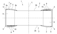
本実施形態の切削インサートは、超硬合金等の硬質材料によって多角形の板状に形成されたインサート本体1を備えており、このインサート本体1の多角形面2は、本実施形態ではインサート中心線Lを中心とする概略長方形面状に形成されている。インサート中心線Lは、多角形面2の中心を通過するインサート本体の厚み方向に平行な線である。インサート本体1には、このインサート中心線Lを中心とする断面円形の取付孔1Aが、インサート本体1を貫通するように形成されて、表裏の多角形面2の中央部に開口している。The cutting insert of this embodiment has an
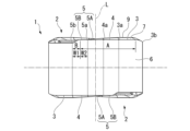
このインサート本体1の前記多角形面2の辺稜部には、インサート中心線L方向から見た平面視において図2に示すように、多角形面2のコーナ部に、インサート中心線Lに平行なコーナ刃中心線Cを中心とした凸円弧状をなすコーナ刃3が形成されている。また、このコーナ刃3のコーナ刃第1端部3a(多角形面2がなす長方形における短辺側のコーナ刃3の端部)からは、コーナ刃3の接線方向に直線状に延びる主切刃4が形成されている。2, in a plan view seen from the insert center line L direction, a
さらに、この主切刃4の前記コーナ刃第1端部3aとは反対側の主切刃第1端部4aからは、主切刃4の主切刃第1端部4a側への延長線に対して多角形面2の内側に後退する副切刃5が形成されている。この副切刃5は、本実施形態では、前記平面視において、コーナ刃3よりも半径の大きい凸円弧状をなして前記主切刃第1端部4aにおいて主切刃4に接する第1副切刃5Aと、この第1副切刃5Aの前記主切刃第1端部4aとは反対側の副切刃第1端部5aにおいて第1副切刃5Aと接して直線状に延びる第2副切刃5Bとを備えている。
Furthermore, a
本実施形態において、表裏の多角形面2がなす長方形面は、インサート中心線Lを中心として180°回転対称に形成されており、この長方形面の1つの対角線上に位置する2つの角部が配置されるコーナ部(図2において右下と左上のコーナ部)にコーナ刃3が形成されている。また、主切刃4と副切刃5は、このコーナ刃3に連なる前記長方形面の短辺部に形成される。さらに、本実施形態のインサート本体1は、表裏反転対称形状に形成されており、従って1つのインサート本体1に4組のコーナ刃3、主切刃4および副切刃5が形成される。In this embodiment, the rectangular surface formed by the
ここで、インサート本体1において表裏の多角形面2の間に延びる側面には、コーナ刃3、主切刃4、および副切刃5に連なる逃げ面6が形成される。この逃げ面6も含めて、インサート本体1の側面はインサート中心線Lに平行に延びており、本実施形態の切削インサートはネガティブタイプの切削インサートとされる。この逃げ面6のうち、副切刃5の第1副切刃5Aに連なる部分は、表裏の多角形面2の同じ短側面に形成された第1副切刃5A同士で共通の逃げ面6とされている。Here, a
一方、前記多角形面2には、コーナ刃3、主切刃4、および副切刃5の全長に渡って、図5~図7に示すように多角形面2の内側に向かうに従いインサート中心線L方向に、インサート本体1の外側に向けて漸次突出するランド部7が、これらコーナ刃3、主切刃4、および副切刃5に沿って形成されるとともに、このランド部7よりも多角形面2の内側には、多角形面2の内側に向かうに従いインサート中心線L方向に、インサート本体1の内側に向けて漸次後退するすくい面部8が形成されている。また、これらランド部7とすくい面部8との間には、コーナ刃中心線Cに沿った断面と主切刃4と副切刃5に直交する断面とにおいてランド部7とすくい面部8とに接する凸曲線状の頂部9が形成されている。On the other hand, the
さらに、すくい面部8よりも多角形面2の内側には、やはりコーナ刃中心線Cに沿った断面において図5~図7に示すように、多角形面2の内側へのすくい面部8の延長線Mに対して多角形面2の内側に向かうに従いインサート中心線L方向に漸次後退する後壁面部10が形成されている。また、この後壁面部10よりも多角形面2の内側には、多角形面2の内側に延びて取付孔1Aの開口部が形成されるインサート中心線Lに垂直な平面であるボス面2Aが形成されている。
Furthermore, as shown in Figures 5 to 7 in a cross section along the corner blade centerline C, a
ここで、ランド部7は、コーナ刃中心線Cに沿った断面と主切刃4と副切刃5に直交する断面とにおいて直線状に形成されていてもよいが、本実施形態では図5~図7に示すようにコーナ刃中心線C方向に僅かに凸曲する凸曲線状に形成されている。また、すくい面部8も、コーナ刃中心線Cに沿った断面と主切刃4と副切刃5に直交する断面とにおいて直線状に形成されていてもよいが、本実施形態では同じく図5~図7に示すように、コーナ刃中心線C方向に僅かに凸曲する凸曲線状に形成されている。Here, the
さらにまた、後壁面部10は、コーナ刃中心線Cに沿った断面において図5~図7に示すように、本実施形態では後述するように直線状となるすくい面部8の延長線Mに対し、多角形面2の内側に向かうに従い凸曲線をなしてインサート中心線L方向に後退した後、この凸曲線に接する凹曲線をなしてインサート中心線L方向に後退し、ボス面2Aに接するように形成されている。Furthermore, as shown in Figures 5 to 7 in a cross section along the corner blade center line C, in this embodiment, the rear
そして、コーナ刃3の前記コーナ刃第1端部3aから、コーナ刃3に沿ってコーナ刃第1端部3aとは反対側のコーナ刃第2端部3bに向けてコーナ刃中心線Cを中心に40°の範囲内では、コーナ刃中心線Cに沿った断面において図5~図7に示すように、ランド部7のインサート中心線Lに垂直な基準面Pに対する傾斜角θ1が、すくい面部8のインサート中心線Lに垂直な基準面Pに対する傾斜角θ2以上とされている。なお、図5~図7においては、インサート中心線Lに垂直な基準面Pの位置をボス面2Aの位置に合わせてある。
And within a range of 40° from the corner blade
また、コーナ刃中心線Cに沿った断面において、図5~図7に示すコーナ刃3に連なるランド部7の傾斜角θ1は、15°~25°の範囲内とされるのが望ましく、本実施形態ではコーナ刃3の全長に渡って20°で一定とされている。
In addition, in a cross section along the corner blade center line C, the inclination angle θ1 of the
これに対して、コーナ刃中心線Cに沿った断面において、図7に示すコーナ刃第1端部3aにおけるすくい面部8の傾斜角θ2は17.1°とされ、図6に示すコーナ刃第1端部3aからコーナ刃第2端部3bに向けてコーナ刃中心線C回りに40°の位置であるとともに、コーナ刃第2端部3bからコーナ刃第1端部3aに向けてコーナ刃中心線C回りに40°でもある位置のすくい面部8の傾斜角θ2は16.4°とされ、図5に示すコーナ刃3のコーナ刃第2端部3bにおけるすくい面部8の傾斜角θ2は14.4°とされている。すなわち、本実施形態では、コーナ刃3に沿ってコーナ刃第1端部3aとは反対側のコーナ刃第2端部3bからコーナ刃第1端部3aに向けてコーナ刃中心線Cを中心に40°の範囲内でも、コーナ刃中心線Cに沿った断面において、ランド部7のインサート中心線Lに垂直な基準面Pに対する傾斜角θ1は、すくい面部8のインサート中心線Lに垂直な基準面Pに対する傾斜角θ2以上とされ、コーナ刃3の全長に渡ってランド部7の傾斜角θ1がすくい面部8の傾斜角θ2以上とされ、特に傾斜角θ1は傾斜角θ2よりも大きくされている。なお、このコーナ刃3にランド部7および頂部9を介して連なるすくい面部8の傾斜角θ2は、5°~20°の範囲内とされるのが望ましい。In contrast, in a cross section along the corner blade center line C, the inclination angle θ2 of the
ここで、本実施形態では、ランド部7のコーナ刃中心線Cに沿った断面は上述のように僅かに凸曲する凸曲線状をなしているので、このランド部7の傾斜角θ1は、図5~図7に示すようにコーナ刃中心線Cに沿った断面において、コーナ刃3と、頂部9のインサート中心線L方向に最も突出した頂点9aとを結ぶ直線Nの前記基準面Pに対する傾斜角とされる。ただし、ランド部7がコーナ刃中心線Cに沿った断面において上述のように直線状に形成されている場合には、ランド部7の傾斜角θ1は、この直線の基準面Pに対する傾斜角とすればよい。Here, in this embodiment, since the cross section of the
また、本実施形態では、すくい面部8も、コーナ刃中心線Cに沿った断面が上述のように僅かに凸曲する凸曲線状をなしているので、このすくい面部8の傾斜角θ2は、図5~図7に示すようにコーナ刃中心線Cに沿った断面において、頂部9の前記頂点9aと、すくい面部8から後壁面部10がインサート中心線L方向に後退し始めるすくい面部8の後壁面部10との接点8aとを結ぶ直線の前記基準面Pに対する傾斜角、すなわちこの直線の多角形面2の内側への延長線Mと基準面P(ボス面2A)との交差角とされる。In addition, in this embodiment, the cross section of the scooping
ただし、このすくい面部8についても、コーナ刃中心線Cに沿った断面において上述のように直線状をなしている場合には、すくい面部8の傾斜角θ2は、この直線の前記基準面Pに対する傾斜角、すなわちコーナ刃中心線Cに沿った断面におけるすくい面部8がなす直線の多角形面2の内側への延長線Mと基準面Pとの交差角とすればよい。However, when the cutting
さらに、本実施形態では、コーナ刃3に沿ってコーナ刃第1端部3aからコーナ刃第2端部3bに向けてコーナ刃中心線Cを中心に40°の範囲内では、コーナ刃中心線Cに沿った断面において図5~図7に示すように、コーナ刃3から頂部9のインサート中心線L方向における前記頂点9aまでのコーナ刃中心線Cに垂直な方向の距離H1が、この頂部9の頂点9aからすくい面部8の多角形面2の内側への延長線Mとボス面2Aとの交点2aまでのコーナ刃中心線Cに垂直な方向の距離H2以下とされている。Furthermore, in this embodiment, within a range of 40° from the corner blade center line C along the
ただし、本実施形態のように、すくい面部8もコーナ刃中心線Cに沿った断面においてコーナ刃中心線C方向に僅かに凸曲する凸曲線状に形成されている場合には、すくい面部8の多角形面2の内側への延長線もコーナ刃中心線C方向に僅かに凸曲する凸曲線状となる。However, as in this embodiment, when the cutting
そこで、このような場合に、前記距離H2は、図5~図7に示すように、すくい面部8から後壁面部10がインサート中心線L方向に後退し始めるすくい面部8と後壁面部10との接点8aと頂部9の前記頂点9aとを結ぶ直線における多角形面2の内側への前記延長線Mと、前記ボス面2Aとの交点までの頂部9の前記頂点9aからのコーナ刃中心線Cに垂直な方向の距離とすればよい。Therefore, in such a case, the distance H2 may be determined as the distance perpendicular to the corner cutting edge center line C from the
さらにまた、本実施形態では、コーナ刃3に沿ってコーナ刃第1端部3aからコーナ刃第2端部3bに向けてコーナ刃中心線Cを中心に40°の範囲内では、コーナ刃中心線Cに沿った断面において図5~図7に示すように、頂部9の前記頂点9aから前記後壁面部10のボス面2Aとの接点または交点(本実施形態では接点10a)までのコーナ刃中心線Cに垂直な方向の距離H3と、前記頂部9の頂点9aからすくい面部8の多角形面2の内側への延長線Mとボス面2Aとの交点2aまでのコーナ刃中心線Cに垂直な方向の前記距離H2との比H3/H2が0.45~0.75の範囲内とされている。Furthermore, in this embodiment, within a range of 40° from the corner blade center line C along the
なお、特にコーナ刃第1端部3aにおける距離H1は0.35mm~0.45mmの範囲内とされるのが望ましく、本実施形態ではコーナ刃3の全長に渡って距離H1は0.4mmで一定である。これに対して、図7に示すコーナ刃第1端部3aにおける距離H2は1.1mm、距離H3は0.8mmとされ、図6に示すコーナ刃第1端部3aからコーナ刃第2端部3bに向けてコーナ刃中心線C回りに40°の位置の距離H2は1.2mm、距離H3は0.7mmとされ、図5に示すコーナ刃3のコーナ刃第2端部3bにおける距離H2は0.7mm、距離H3は0.4mmとされている。In particular, it is desirable that the distance H1 at the
すなわち、本実施形態では、コーナ刃3に沿ってコーナ刃第2端部3bからコーナ刃第1端部3aに向けてコーナ刃中心線Cを中心に40°の範囲内でも、距離H1が距離H2以下とされ、コーナ刃3の全長に渡って距離H1は距離H2以下とされている。また、コーナ刃3に沿ってコーナ刃第1端部3aからコーナ刃第2端部3bに向けてコーナ刃中心線Cを中心に40°の範囲内では比H3/H2が0.45~0.75の範囲内とされるとともに、コーナ刃3に沿ってコーナ刃第2端部3bからコーナ刃第1端部3aに向けてコーナ刃中心線Cを中心に40°の範囲内でも、比H3/H2が0.45~0.75の範囲内とされている。That is, in this embodiment, even within a range of 40° from the corner blade centerline C from the corner blade
さらに、本実施形態では、コーナ刃3に沿ってコーナ刃第2端部3bからコーナ刃第1端部3aに向けてコーナ刃中心線Cを中心に40°の範囲内では、後壁面部10とボス面2Aとの接線または交線(本実施形態では、接線Q)は、前記平面視において図2に示すように円弧状に形成されている。そして、この平面視において、コーナ刃3がなす円弧の半径G1に対し、後壁面部10とボス面2Aとの接線Qの円弧の半径G2がなす比G2/G1は、本実施形態では0.23~0.87の範囲内とされている。
Furthermore, in this embodiment, within a range of 40° from the corner blade centerline C along the
一方、本実施形態では、前記コーナ刃3に、インサート中心線Lに垂直な基準面Pに平行な方向に沿って延びる平行領域Aが形成されている。ここで、本実施形態におけるコーナ刃3は、図4に示すようにコーナ刃第2端部3bでは、インサート中心線L方向においてボス面2Aに近い位置に位置している。On the other hand, in this embodiment, the
そして、コーナ刃3は、このコーナ刃第2端部3bからコーナ刃第1端部3aに向かうに従い図4に示すようにインサート中心線L方向に漸次突出しつつ、コーナ刃第2端部3bからコーナ刃第1端部3aに向けて延び、コーナ刃中心線C回りにコーナ刃第2端部3bから40°の位置よりも手前の位置において前記インサート中心線Lに垂直な基準面Pに平行な方向に沿って延びる前記平行領域Aに至る。また、コーナ刃3は、この平行領域Aに至った後は基準面Pに平行な方向に延び、コーナ刃第1端部3aに達して主切刃4に連なる。
As shown in FIG. 4, the
さらに、本実施形態では、こうしてコーナ刃3が連なった主切刃4と、この主切刃4に連なる副切刃5のうち、主切刃4側の第1副切刃5Aも、図3に示すようにコーナ刃第1端部3aを通りインサート中心線Lに垂直な基準面Pに平行な方向に沿って延びる平行領域A上に位置している。一方、この第1副切刃5Aに連なる第2副切刃5Bは、本実施形態では副切刃第1端部5aとは反対側の副切刃第2端部5bに向かうに従いインサート中心線L方向に漸次後退する傾斜領域Bを備えている。Furthermore, in this embodiment, the
ここで、本実施形態では、図3に示すように、第2副切刃5Bのうち副切刃第1端部5a側の部分は、インサート中心線Lに垂直な基準面Pに平行な方向に沿って延びる平行領域Aとされている。そして、この平行領域Aよりも副切刃第2端部5b側の部分が、この副切刃第2端部5b側に向かうに従いインサート中心線L方向に凸となる凸曲線を描きつつインサート中心線L方向に後退した後に一定の傾斜角でインサート中心線L方向に漸次後退する傾斜領域Bとされている。Here, in this embodiment, as shown in Figure 3, the portion of the second
また、副切刃5の逃げ面6に対向する方向から見て図3に示すように、第2副切刃5Bにおける傾斜領域Bのインサート中心線Lに垂直な方向の幅W1は、本実施形態では第2副切刃5Bにおける平行領域Aのインサート中心線Lに垂直な方向の幅W2よりも大きくされている。
Furthermore, as shown in Figure 3 when viewed from the direction facing the
さらに、図示は略するが、副切刃第1端部5aにおいて副切刃5に直交する断面におけるランド部7の傾斜角θ1は15°~35°の範囲内とされるのが望ましく、本実施形態では20°とされている。また、同じく副切刃第1端部5aにおいて副切刃5に直交する断面におけるランド部7のインサート中心線Lに垂直な方向の距離は0.15mm~0.45mmの範囲内とされるのが望ましく、本実施形態では0.4mmとされている。
Furthermore, although not shown, the inclination angle θ1 of the
ここで、このような超硬合金等の硬質材料により形成される切削インサートのインサート本体1は、粉末冶金技術の基本的な工程に沿って製造される。すなわち、インサート本体1が超硬合金製の場合は、炭化タングステン粉末とコバルト粉末を主成分として、必要に応じてクロムやタンタル等を副成分とする顆粒状の造粒粉末を用いて、金型を用いた粉末プレス成形を行う。Here, the
こうして得られたプレス成形体は、適切な雰囲気と温度に制御された焼結炉内で所定の時間焼結することにより、インサート本体1となる焼結体を製造することができる。インサート本体1の基本的形状は前記金型の設計により反映され、インサート本体1の詳細形状は金型成形によって得られる。さらに、インサート本体1の刃先形状の高精度化を図るために、必要に応じて研削砥石を用いた研削加工を施すこともある。The press-molded body thus obtained can be sintered for a prescribed time in a sintering furnace with appropriate atmosphere and temperature control to produce a sintered body that will become the
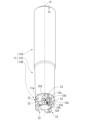
このような構成の切削インサートは、図8および図9に示す刃先交換式切削工具の工具本体11の先端部外周に形成されたインサート取付座12に着脱可能に取り付けられて、図10および図11に示す本発明の刃先交換式切削工具の一実施形態を構成する。こうしてインサート取付座12に取り付けられた切削インサートは、工具本体11が軸線O回りに工具回転方向Tに回転させられつつ軸線Oに交差する方向に送り出されることにより、前記コーナ刃3、主切刃4、および副切刃5によって被削材に切削加工を行う。A cutting insert of this configuration is removably attached to an
工具本体11は鋼材等の金属材料により前記軸線Oを中心とする概略円柱軸状に一体に形成されており、その後端部(図8~図11において上側部分)は円柱状のままのシャンク部11Aとされるとともに、先端部(図8~図11において下側部分)はシャンク部11Aよりも小径の切刃部11Bとされていて、この切刃部11Bに前記インサート取付座12が形成されている。また、シャンク部11Aと切刃部11Bとの間には、工具本体11の先端側に向かうに従い縮径するテーパネック部11Cが形成されている。The
工具本体11の切刃部11Bの外周には、凹溝状のチップポケット13が周方向に間隔をあけて複数(本実施形態では、周方向に等間隔に4つ)形成されており、前記インサート取付座12は、これらのチップポケット13の工具回転方向Tを向く壁面の先端部に、工具回転方向Tとは反対側に凹む凹所として形成されている。なお、チップポケット13の工具回転方向Tとは反対側を向く壁面には、工具本体11内に形成されたクーラント孔11aが開口している。A plurality of groove-shaped chip pockets 13 (four evenly spaced in the circumferential direction in this embodiment) are formed on the outer periphery of the
インサート取付座12は、工具回転方向Tを向く底面12aと、この底面12aの工具本体11における内周側から工具回転方向Tに延びて外周側を向く壁面12b、および底面12aの工具本体11における後端側から工具回転方向Tに延びて先端側を向く壁面12cとを備えている。また、底面12aと壁面12b、12c同士が交差する隅角部および壁面12b、12c同士が交差する隅角部には、凹溝状の逃げ部12dが形成されている。The
底面12aは、切削インサートのインサート本体1における多角形面2のボス面2Aよりも一回り小さな相似形の平面状に形成されており、工具本体11の後端側に向かうに従い工具回転方向T側に向かうように僅かに傾斜している。また、この底面12aの中央部にはネジ孔12eが底面12aに垂直に形成されている。The
このようなインサート取付座12に、前記実施形態の切削インサートは、インサート本体1の一方の多角形面2を工具回転方向Tに向けるとともに他方の多角形面2のボス面2Aを底面12aに密着させ、前記一方の多角形面2の1つのコーナ部に形成されたコーナ刃3を工具本体11の先端外周側に向けるとともに、このコーナ刃3のコーナ刃第1端部3aから延びる主切刃4が工具本体11の内周側に向かうようにして着座させられる。このとき、前記1つのコーナ部とは前記一方の多角形面2の対角線上に位置する他の1つのコーナ部に交差するインサート本体1の2つの側面は、壁面12b、12cに当接させられる。The cutting insert of the embodiment is seated on such an
そして、こうして着座させられた切削インサートは、工具回転方向T側から取付孔1Aに挿通されたクランプネジ14が底面12aのネジ孔12eにねじ込まれることにより、他方の多角形面2のボス面2Aが底面12aに押し付けられるとともに、前記一方の多角形面2の他の1つのコーナ部に交差する2つの側面が壁面12b、12cに押圧されてインサート取付座12に着脱可能に取り付けられる。
The cutting insert thus seated is then removably attached to the
こうしてインサート取付座12に取り付けられた切削インサートは、底面12aが上述のように傾斜していることから、インサート中心線Lが工具回転方向Tとは反対側に向かうに従い工具本体11の後端側に僅かに傾けられ、これによって工具本体11の先端外周側に向けられたコーナ刃3と、このコーナ刃3から工具本体11の内周側に延びる主切刃4および副切刃5の逃げ面6には逃げ角が与えられる。
Because the cutting insert attached to the
また、この工具本体11の先端外周側に向けられたコーナ刃3から工具本体11の内周側に延びる主切刃4は、内周側に向かうに従い工具本体11の先端側に向かうように僅かに傾斜させられる。すなわち、本実施形態の刃先交換式切削工具は、刃先交換式のラジアスエンドミルである。さらに、この主切刃4に連なる副切刃5は、主切刃第1端部4aと副切刃第1端部5aとを結ぶ直線が工具本体11の軸線Oに垂直な平面上に位置するように配設される。
The
このように刃先交換式切削工具の工具本体11に取り付けられた前記構成の切削インサートにおいては、上述したように前記多角形面2に、コーナ刃3から多角形面2の内側に向かうに従いインサート中心線L方向に漸次突出するランド部7と、このランド部7よりも多角形面2の内側に向かうに従いインサート中心線L方向に漸次後退するすくい面部8とが形成されている。In the cutting insert of the above configuration attached to the
そして、コーナ刃3に沿ってコーナ刃第1端部3aからコーナ刃第2端部3bに向けてコーナ刃中心線Cを中心に40°の範囲内においては、コーナ刃中心線Cに沿った断面において、前記ランド部7のインサート中心線Lに垂直な基準面Pに対する傾斜角θ1が、前記すくい面部8のインサート中心線Lに垂直な基準面Pに対する傾斜角θ2以上とされている。
And within a range of 40° from the corner blade
このため、上述のように構成された切削インサートおよび刃先交換式切削工具では、専ら切削加工に使用されるコーナ刃3のコーナ刃第1端部3aからコーナ刃第2端部3bに向けてコーナ刃中心線C回りに40°の範囲内で、コーナ刃3に連なる多角形面2上のインサート本体1のコーナ刃中心線Cに沿った断面の断面積を特にコーナ刃3側で大きく確保することができる。Therefore, in the cutting insert and replaceable cutting tool configured as described above, the cross-sectional area of the cross section along the corner blade center line C of the
従って、このコーナ刃3に連なる多角形面2上のインサート本体1の肉厚を厚くして高い切刃強度を与えることができるので、コーナ刃3の耐欠損性を向上させることができ、高硬度の被削材を切削加工する場合においても、長期に渡って安定した切削加工を行うことが可能となる。特に、本実施形態では、コーナ刃3に沿ってコーナ刃第2端部3bからコーナ刃第1端部3aに向けてコーナ刃中心線C回りに40°の範囲内でも前記傾斜角θ1が前記傾斜角θ2以上とされ、すなわちコーナ刃3の全長に渡って前記傾斜角θ1が前記傾斜角θ2以上とされているので、コーナ刃3の全長を使用するような場合でも、コーナ刃3の耐欠損性を向上させることができる。Therefore, the thickness of the
また、本実施形態では、これらランド部7とすくい面部8との間に、コーナ刃中心線Cに沿った断面においてランド部7とすくい面部8とに接する凸曲線状の頂部9が形成されるとともに、すくい面部8よりも多角形面2の内側には、コーナ刃中心線Cに沿った断面においてすくい面部8の多角形面2の内側への延長線Mに対して多角形面2の内側に向かうに従いインサート中心線L方向に漸次後退する後壁面部10と、この後壁面部10から多角形面2の内側に延びて取付孔1Aの開口部が形成されるインサート中心線Lに垂直な平面Pであるボス面2Aとが形成されている。In this embodiment, a convex
そして、コーナ刃3に沿ってコーナ刃第1端部3aからコーナ刃第2端部3bに向けてコーナ刃中心線Cを中心に40°の前記範囲内では、コーナ刃中心線Cに沿った断面において、コーナ刃3から頂部9のインサート中心線L方向における頂点9aまでのコーナ刃中心線Cに垂直な方向の距離H1が、頂部9の頂点9aからすくい面部8の多角形面2の内側への延長線Mとボス面2Aとの交点2aまでのコーナ刃中心線Cに垂直な方向の距離H2以下とされている。
Within the above-mentioned range of 40° around the corner blade center line C along the
従って、本実施形態によれば、ランド部7の多角形面2の内側に配設される頂部9からすくい面部8に沿って延長線Mがボス面2Aに達するまでの前記距離H2が、ランド部7の幅である前記距離H1以上となる。このため、コーナ刃3に連なる多角形面2上のインサート本体1のコーナ刃中心線Cに沿った断面の断面積をさらに大きく確保することができ、コーナ刃3に一層高い切刃強度を与えることが可能となって耐欠損性をより確実に向上させることができる。なお、ランド部7の幅である前記距離H1は、本実施形態ではコーナ刃第2端部3bから主切刃第1端部4aにかけて一定である。Therefore, according to this embodiment, the distance H2 from the apex 9 arranged on the inside of the
さらに、本実施形態では、コーナ刃3に沿ってコーナ刃第1端部3aからコーナ刃第2端部3bに向けてコーナ刃中心線Cを中心に40°の前記範囲内で、コーナ刃中心線Cに沿った断面において、前記頂部9の頂点9aから前記後壁面部10とボス面2Aとの接点10aまでのコーナ刃中心線Cに垂直な方向の距離H3と、前記頂部9の頂点9aからすくい面部8の多角形面2の内側への延長線Mとボス面2Aとの交点2aまでのコーナ刃中心線Cに垂直な方向の距離H2との比H3/H2が0.45~0.75の範囲内とされている。Furthermore, in this embodiment, within the above-mentioned range of 40° from the corner blade
このため、切削加工の際にコーナ刃3、主切刃4、および副切刃5によって生成される切屑の排出性を向上させることができるとともに、本実施形態のようにインサート本体1が表裏反転対称形状である場合に、工具本体11のインサート取付座12の前記底面12aに密着させられる着座面となるボス面2Aの面積を大きく確保して、切削インサートを安定してインサート取付座12に着座させることが可能となる。
This improves the discharge of chips generated by the
ここで、この比H3/H2が0.45よりも小さいと、切屑とすくい面部8との接触距離が短くなるため、切屑の排出方向の制御が不安定となるおそれがある。また、この比H3/H2が0.75より大きいと、逆に切屑とすくい面部8との接触距離が長くなって切屑の擦過による切削抵抗が増大するとともに、後壁面部10が多角形面の内側に後退することになるので、上述のようにインサート取付座12の前記底面12aに密着させられる着座面となる多角形面2のボス面2Aの面積が小さくなり、切削インサートの着座安定性が損なわれるおそれがある。Here, if the ratio H3/H2 is smaller than 0.45, the contact distance between the chips and the
さらにまた、本実施形態では、コーナ刃3に沿ってコーナ刃第2端部3bからコーナ刃第1端部3aに向けてコーナ刃中心線Cを中心に40°の範囲内で、前記後壁面部10とボス面2Aとの接線Qが前記平面視において凹円弧状に形成されている。そして、前記平面視において、コーナ刃3がなす円弧の半径G1に対し、後壁面部10とボス面2Aとの接線Qの凹円弧の半径G2がなす比G2/G1が0.23~0.87の範囲内とされている。Furthermore, in this embodiment, a tangent Q between the rear
このため、やはり切削インサートの着座安定性を向上させることができるとともに、切屑の排出方向を制御しやすくなる。すなわち、この比G2/G1が0.23よりも小さいと、後壁面部10が多角形面2の内側に後退してボス面2Aの面積が小さくなり、切削インサートの着座安定性が損なわれるおそれがあるとともに、コーナ刃中心線C方向から見たコーナ刃3から後壁面部10とボス面2Aとの接線Qまでの幅は大きくなり、切屑とランド部7やすくい面部8との接触距離が長くなって切削抵抗が増大するおそれもある。
This also improves the seating stability of the cutting insert and makes it easier to control the direction of chip discharge. In other words, if the ratio G2/G1 is smaller than 0.23, the rear
また、逆にこの比G2/G1が0.87よりも大きいと、コーナ刃中心線C方向から見たコーナ刃3から後壁面部10とボス面2Aとの接線Qまでの幅が小さくなり、切屑とランド部7やすくい面部8との接触距離が短くなってしまうため、切屑の排出方向の制御が不安定となるおそれがある。Conversely, if the ratio G2/G1 is greater than 0.87, the width from the
なお、本実施形態では、後壁面部10がボス面2Aに接しているため、前記距離H3や前記半径G2は、これらボス面2Aと後壁面部10との接点10aや接線Qに基づいているが、後壁面部10がボス面2Aに角度をもって交差している場合には、これらボス面2Aと後壁面部10との交点や交線に基づけばよい。In this embodiment, since the rear
さらに、本実施形態では、前記多角形面2が、インサート中心線Lを中心として180°回転対称に形成された長方形面とされており、この長方形面の1つの対角線上に位置する2つの角部が配置されるコーナ部にコーナ刃3が形成されるとともに、このコーナ刃3に連なる前記長方形面の短辺部に主切刃4と副切刃5とが形成されているので、1つの多角形面2において2つずつのコーナ刃3、主切刃4、および副切刃5を使用することができて、効率的かつ経済的である。Furthermore, in this embodiment, the
しかも、本実施形態では、このような長方形面状の多角形面2を有するインサート本体1が表裏反転対称形状とされており、従って1つのインサート本体1において4組のコーナ刃3、主切刃4、および副切刃5を使用することができるので、さらに一層効率的かつ経済的である。Moreover, in this embodiment, the
一方、本実施形態では、前記コーナ刃3に、インサート中心線Cに垂直な基準面Pに平行な方向に沿って延びる平行領域Aが形成されており、この平行領域Aでは、インサート中心線L方向においてもコーナ刃3からのインサート本体1の肉厚を厚くすることができる。このため、コーナ刃3に高い切刃強度を与えることが可能となるので、例えば多数の孔が空いた被削材の加工面を切削加工する場合でも、コーナ刃3の耐欠損性を一層向上させることができる。On the other hand, in this embodiment, the
また、本実施形態では、この平行領域Aに沿って延びたコーナ刃3とコーナ刃第1端部3aにおいて連なる主切刃4と、この主切刃4に主切刃第1端部4aにおいて連なる副切刃5のうち主切刃4側の第1副切刃5Aも、コーナ刃第1端部3aを通りインサート中心線Lに垂直な基準面Pに平行な方向に沿って延びる平行領域A上に位置している。このため、これら主切刃4および副切刃5の第1副切刃5Aにおいても、インサート中心線L方向の肉厚を確保して切刃強度を向上させることができ、多数の孔が空いた被削材等の切削加工において高い耐欠損性を得ることができる。In this embodiment, the
しかも、本実施形態では、副切刃5において副切刃第1端部5aにおいて第1副切刃5Aに連なる第2副切刃5Bの副切刃第1端部5a側の部分も、コーナ刃第1端部3aを通りインサート中心線Lに垂直な基準面Pに平行な方向に沿って延びる平行領域A上に位置しているので、1刃当たりの送り量が大きい場合でも耐欠損性の向上を図ることが可能となる。なお、この平行領域Aは、厳密にインサート中心線Lに垂直な基準面Pに平行に位置していなくても、例えば製造誤差の範囲にあって基準面Pに対して0.5°以内の角度の誤差があってもよい。Moreover, in this embodiment, the portion of the second
その一方で、副切刃5において第1副切刃5Aに連なる第2副切刃5Bは、本実施形態では副切刃第1端部5aとは反対側の副切刃第2端部5bに向かうに従いインサート中心線L方向に漸次後退する傾斜領域Bを備えている。ここで、この第2副切刃5Bは、インサート本体1がインサート取付座12取り付けられた状態で、工具本体11の内周側に向かうに従い後端側に向かうように僅かに傾斜することになり、工具本体11を軸線Oに対して斜めに送り出す傾斜切削加工を行うときに専ら使用される。従って、本実施形態によれば、このような傾斜切削加工の場合でも、第2副切刃5Bの耐欠損性を向上させることができる。On the other hand, the second
しかも、本実施形態では、副切刃5の逃げ面6に対向する方向から見て、第2副切刃5Bにおける傾斜領域Bのインサート中心線Lに垂直な方向の幅W1が、第2副切刃5Bにおける平行領域Aのインサート中心線Lに垂直な方向の幅W2よりも大きくされている。このため、上述のような傾斜切削加工において切り込み量が大きい場合でも、第2副切刃5Bの耐欠損性を一層確実に確保することができる。Moreover, in this embodiment, when viewed from the direction facing the
また、本実施形態では、コーナ刃中心線Cに沿った断面において、コーナ刃3に連なるランド部7の傾斜角θ1は、15°~25°の範囲内とされており、これは、コーナ刃3と主切刃4との境界となるコーナ刃第1端部3aでも同様である。このため、このコーナ刃3と主切刃4との境界となるコーナ刃第1端部3aにおいて、切削抵抗の低減を図りつつ耐欠損性を維持することができる。
In this embodiment, in a cross section taken along the corner blade center line C, the inclination angle θ1 of the
すなわち、このコーナ刃第1端部3aにおけるランド部7の傾斜角θ1が15°を下回ると、刃物角が小さくなって高硬度の被削材の切削加工における耐欠損性を確保することが困難となるおそれがある。その一方で、このコーナ刃第1端部3aにおけるランド部7の傾斜角θ1が25°を上回ると、ランド部7が立ち上がりすぎて切削抵抗の増大を招くおそれがある。That is, if the inclination angle θ1 of the
さらに、本実施形態では、このコーナ刃3と主切刃4との境界となるコーナ刃第1端部3aにおける前記距離H1が0.35mm~0.45mmの範囲内とされており、これによってもコーナ刃3と主切刃4との境界となるコーナ刃第1端部3aにおいて、切削抵抗の低減を図りつつ耐欠損性を維持することができる。
Furthermore, in this embodiment, the distance H1 at the corner blade
すなわち、このコーナ刃第1端部3aにおけるランド部7の前記距離H1が0.35mmを下回ると、ランド部7が幅狭となって高硬度の被削材の切削加工における耐欠損性を確保することが困難となるおそれがある。その一方で、このコーナ刃第1端部3aにおけるランド部7の前記距離H1が0.45mmを上回ると、ランド部7が長くなって切屑の接触による切削抵抗の増大を招くおそれがある。That is, if the distance H1 of the
さらにまた、本実施形態では、副切刃5の第1副切刃5Aと第2副切刃5Bのと境界となる副切刃第1端部5aにおいて副切刃5に直交する断面におけるランド部7の傾斜角θ1が15°~35°の範囲内とされている。このため、このコーナ刃第1端部3aにおける耐欠損性の向上を図るとともに切削抵抗の低減を促すことができる。Furthermore, in this embodiment, the inclination angle θ1 of the
すなわち、この副切刃第1端部5aにおけるランド部7の傾斜角θ1が15°を下回ると、副切刃5の刃物角が小さくなって高硬度の被削材を切削加工する際に欠損が生じ易くなってしまう。その一方で、この副切刃第1端部5aにおけるランド部7の傾斜角θ1が35°を上回ると、やはり副切刃5のランド部7が立ち上がりすぎて切削抵抗の増大を招くおそれがある。That is, if the inclination angle θ1 of the
また、本実施形態では、同じく副切刃第1端部5aにおいて副切刃5に直交する断面におけるランド部7のインサート中心線Lに垂直な方向の距離は0.15mm~0.45mmの範囲内とされており、これによってもコーナ刃第1端部3aにおける耐欠損性の向上を図るとともに切削抵抗の低減を促すことができる。
In addition, in this embodiment, the distance perpendicular to the insert center line L of the
すなわち、この副切刃第1端部5aにおけるランド部7のインサート中心線Lに垂直な方向の距離は0.15mmを下回ると、ランド部7が短くなって高硬度の被削材を切削加工する際に欠損が生じ易くなってしまう。その一方で、この副切刃第1端部5aにおけるランド部7のインサート中心線Lに垂直な方向の距離が0.45mmを上回ると、やはり副切刃5のランド部7が長くなりすぎて切屑の接触による切削抵抗の増大を招くおそれがある。That is, if the distance of the
次に、図12~図18は、本発明の切削インサートにおける第2の実施形態を示すものであり、図19~図25は、本発明の切削インサートにおける第3の実施形態を示すものであり、図26~図32は、本発明の切削インサートにおける第4の実施形態を示すものである。これら第2~第4の実施形態の切削インサートにおいて、図1~図7に示した本発明の第1の実施形態の切削インサートと共通する部分には、同一の符号を配して説明を省略する。12 to 18 show a second embodiment of the cutting insert of the present invention, 19 to 25 show a third embodiment of the cutting insert of the present invention, and 26 to 32 show a fourth embodiment of the cutting insert of the present invention. In the cutting inserts of the second to fourth embodiments, parts common to the cutting insert of the first embodiment of the present invention shown in Figs. 1 to 7 are assigned the same reference numerals and will not be described.
図12~図18に示す第2の実施形態の切削インサートでは、コーナ刃中心線Cに沿った断面において、図18に示すコーナ刃第1端部3aにおけるすくい面部8の傾斜角θ2は17.0°とされるとともに、前記距離H3は0.9mmとされており、図17に示すコーナ刃第1端部3aからコーナ刃第2端部3bに向けてコーナ刃中心線C回りに40°の位置におけるすくい面部8の傾斜角θ2は16.3°とされ、図16に示すコーナ刃3のコーナ刃第2端部3bにおけるすくい面部8の傾斜角θ2は14.2°とされるとともに、前記距離H2は0.8mmとされている。これら以外の諸元は第1の実施形態と同じである。
In the cutting insert of the second embodiment shown in Figures 12 to 18, in a cross section along the corner blade center line C, the inclination angle θ2 of the
また、図19~図25に示す第3の実施形態の切削インサートでは、コーナ刃中心線Cに沿った断面において、図25に示すコーナ刃第1端部3aにおけるランド部7の傾斜角θ1は20°、すくい面部8の傾斜角θ2は17°、前記距離H2は1.1mmとされ、図24に示すコーナ刃第1端部3aからコーナ刃第2端部3bに向けてコーナ刃中心線C回りに40°の位置におけるすくい面部8の傾斜角θ2は16.9°、前記距離H2は1.1mm、前記距離H3は0.8mmとされ、図23に示すコーナ刃3のコーナ刃第2端部3bにおけるランド部7の傾斜角θ1は20°、すくい面部8の傾斜角θ2は9.3°、前記距離H2は1.3mm、前記距離H3は0.5mmとされている。これら以外の諸元は第1の実施形態と同じである。
In the cutting insert of the third embodiment shown in Figures 19 to 25, in the cross section along the corner blade center line C, the inclination angle θ1 of the
さらに、図26~図32に示す第4の実施形態の切削インサートでは、図32に示すコーナ刃第1端部3aにおけるすくい面部8の傾斜角θ2は16.9°、前記距離H2は1.1mmとされ、図31に示すコーナ刃第1端部3aからコーナ刃第2端部3bに向けてコーナ刃中心線C回りに40°の位置におけるすくい面部8の傾斜角θ2は16.9°、前記距離H2は1.1mm、前記距離H3は0.8mmとされ、図30に示すコーナ刃3のコーナ刃第2端部3bにおけるランド部7の傾斜角θ1は20°、すくい面部8の傾斜角θ2は11.5°、前記距離H2は1.0mm、前記距離H3は0.5mmとされている。これら以外の諸元は第1の実施形態と同じである。
Furthermore, in the cutting insert of the fourth embodiment shown in Figures 26 to 32, the inclination angle θ2 of the
このような第2~第4の実施形態の切削インサートにおいても、ランド部7の前記傾斜角θ1がすくい面部8の前記傾斜角θ2以上とされているので、第1の実施形態と同様の効果を得ることができる。ただし、このうち第3、第4の実施形態では、副切刃5の逃げ面6に対向する方向から見て、第2副切刃5Bにおける傾斜領域Bのインサート中心線Lに垂直な方向の幅W1は、第2副切刃5Bにおける平行領域Aのインサート中心線Lに垂直な方向の幅W2よりも大きくされてはおらず、略等しいか、第2副切刃5Bにおける傾斜領域Bのインサート中心線Lに垂直な方向の幅W1が、第2副切刃5Bにおける平行領域Aのインサート中心線Lに垂直な方向の幅W2よりも小さくされている。In the cutting inserts of the second to fourth embodiments, the inclination angle θ1 of the
刃先交換式切削工具を用いて、高硬度の被削材を切削加工する場合においても、長期に渡って安定した切削加工を行うことができる。 Even when cutting high-hardness workpieces using indexable cutting tools, stable cutting can be performed over a long period of time.
1 インサート本体
1A 取付孔
2 多角形面
2A ボス面
2a コーナ刃中心線Cに沿った断面における頂部9の頂点9aからすくい面部8の多角形面2の内側への延長線Mとボス面2Aとの交点
3 コーナ刃
3a コーナ刃第1端部
3b コーナ刃第2端部
4 主切刃
4a 主切刃第1端部
5 副切刃
5A 第1副切刃
5B 第2副切刃
5a 副切刃第1端部
5b 副切刃第2端部
6 逃げ面
7 ランド部
8 すくい面部
8a すくい面部8の後壁面部10との接点
9 頂部
9a 頂部9の頂点
10 後壁面部
10a コーナ刃中心線Cに沿った断面における後壁面部10とボス面2Aとの接点
11 工具本体
12 インサート取付座
13 チップポケット
14 クランプネジ
L インサート中心線
C コーナ刃中心線
M コーナ刃中心線Cに沿った断面における頂部9の頂点9aからすくい面部8の多角形面2の内側への延長線
N コーナ刃中心線Cに沿った断面におけるコーナ刃3と頂部9の頂点9aとを結ぶ直線
P 基準面
Q ボス面2Aと後壁面部10との接線
θ1 ランド部7の傾斜角
θ2 すくい面部8の傾斜角
H1 コーナ刃中心線Cに沿った断面におけるコーナ刃3から頂部9の頂点9aまでのコーナ刃中心線Cに垂直な方向の距離
H2 コーナ刃中心線Cに沿った断面における頂部9の頂点9aから交点2aまでのコーナ刃中心線Cに垂直な方向の距離
H3 コーナ刃中心線Cに沿った断面における頂部9の頂点9aから接点10aまでのコーナ刃中心線Cに垂直な方向の距離
A 平行領域
B 傾斜領域
G1 コーナ刃3がなす円弧の半径
G2 接線Qがなす円弧の半径
W1 第2副切刃5Bにおける傾斜領域Bのインサート中心線Lに垂直な方向の幅
W2 第2副切刃5Bにおける平行領域Aのインサート中心線Lに垂直な方向の幅
O 工具本体11の軸線
T 工具回転方向
1 Insert body 1A Mounting hole 2 Polygonal surface 2A Boss surface 2a Intersection of boss surface 2A and extension line M from apex 9a of apex 9 to inside of polygonal surface 2 of rake surface portion 8 in cross section along corner blade center line C 3 Corner blade 3a Corner blade first end 3b Corner blade second end 4 Main cutting edge 4a Main cutting edge first end 5 Minor cutting edge 5A First minor cutting edge 5B Second minor cutting edge 5a Minor cutting edge first end 5b Minor cutting edge second end 6 Relief surface 7 Land portion 8 Rake surface portion 8a Contact point with rear wall surface portion 10 of rake surface portion 8 9 Apex 9a Apex of apex 9 10 Rear wall surface portion 10a Contact point between rear wall surface portion 10 and boss surface 2A in cross section along corner blade center line C 11 Tool body 12 Insert mounting seat 13 Chip pocket 14 Clamp screw L Insert center line C Corner blade center line M Extension line from vertex 9a of apex 9 to the inside of polygonal surface 2 of rake surface 8 in cross section along corner blade center line C N Straight line connecting corner blade 3 and vertex 9a of apex 9 in cross section along corner blade center line C P Reference surface Q Tangent to boss surface 2A and rear wall surface 10 θ1 Inclined angle of land portion 7 θ2 Inclined angle of rake surface 8 H1 Distance in a direction perpendicular to corner blade center line C from corner blade 3 to vertex 9a of apex 9 in cross section along corner blade center line C H2 Distance in a direction perpendicular to corner blade center line C from vertex 9a of apex 9 to intersection point 2a in cross section along corner blade center line C H3 Distance in a direction perpendicular to corner blade center line C from vertex 9a of apex 9 to contact point 10a in cross section along corner blade center line C A Parallel region B: Inclined region G1: Radius of the arc formed by the corner edge 3 G2: Radius of the arc formed by the tangent line Q W1: Width of the inclined region B of the second minor cutting edge 5B in a direction perpendicular to the insert center line L W2: Width of the parallel region A of the second minor cutting edge 5B in a direction perpendicular to the insert center line L O: Axis of the tool body 11 T: Tool rotation direction
Claims (9)
前記インサート中心線方向から見た平面視において、前記多角形面の辺稜部には、該多角形面のコーナ部に、前記インサート中心線に平行なコーナ刃中心線を中心とした凸円弧状をなすコーナ刃が形成されるとともに、このコーナ刃のコーナ刃第1端部からは該コーナ刃の接線方向に直線状に延びる主切刃が形成され、この主切刃の前記コーナ刃第1端部とは反対側の主切刃第1端部からは該主切刃の前記主切刃第1端部側への延長線に対して後退する副切刃が形成された切削インサートであって、
前記多角形面には、前記コーナ刃から前記多角形面の内側に向かうに従い前記インサート中心線方向に漸次突出するランド部が形成され、
前記ランド部よりも前記多角形面の内側には、該多角形面の内側に向かうに従い前記インサート中心線方向に漸次後退するすくい面部が形成され、
前記ランド部と前記すくい面部との間には、前記コーナ刃中心線に沿った断面において前記ランド部と前記すくい面部とに接する凸曲線状の頂部が形成され、
前記すくい面部よりも前記多角形面の内側には、前記コーナ刃中心線に沿った断面において前記すくい面部の前記多角形面の内側への延長線に対して前記多角形面の内側に向かうに従い前記インサート中心線方向に漸次後退する後壁面部が形成されており、
前記コーナ刃中心線に沿った断面において、前記頂部の前記インサート中心線方向に最も突出した頂点と前記コーナ刃とを結ぶ直線の前記インサート中心線に垂直な基準面に対する角度を、前記基準面に対する前記ランド部の傾斜角θ1とし、
前記頂部の前記頂点と、前記すくい面部から前記後壁面部が前記インサート中心線方向に後退し始める前記すくい面部の前記後壁面部との接点とを結ぶ直線の前記基準面に対する角度を、前記基準面に対する前記すくい面部の傾斜角θ2とするとき、
前記コーナ刃に沿って前記コーナ刃第1端部から、該コーナ刃第1端部とは反対側のコーナ刃第2端部に向けて前記コーナ刃中心線を中心に40°の範囲内では、前記傾斜角θ1が、前記傾斜角θ2以上であることを特徴とする切削インサート。 An insert body formed in a polygonal plate shape has a mounting hole on each of the polygonal surfaces on the front and back sides thereof, the mounting hole penetrating the insert body and centered on the insert center line;
a corner edge having a convex arc shape centered on a corner edge center line parallel to the insert center line at a corner portion of the polygonal surface in a plan view seen from the insert center line direction, a main cutting edge extending linearly from a corner edge first end of the corner edge in a tangential direction of the corner edge, and a minor cutting edge receding from a main cutting edge first end on a side opposite to the corner edge first end of the main cutting edge with respect to an extension line of the main cutting edge toward the main cutting edge first end side,
a land portion is formed on the polygonal surface, the land portion gradually protruding in the direction of the insert center line from the corner edge toward the inside of the polygonal surface,
a rake surface portion is formed on the inside of the polygonal surface relative to the land portion, the rake surface portion gradually receding toward the center line of the insert as it moves toward the inside of the polygonal surface;
a convex curved apex portion is formed between the land portion and the rake face portion in a cross section along the center line of the corner edge, the apex portion being in contact with the land portion and the rake face portion;
a rear wall surface portion is formed on the inside of the polygonal surface relative to the rake surface portion, the rear wall surface portion being gradually recessed toward the insert center line as it moves toward the inside of the polygonal surface with respect to an extension line of the rake surface portion toward the inside of the polygonal surface in a cross section taken along the center line of the corner edge,
In a cross section along the center line of the corner edge, an angle of a straight line connecting the apex of the top portion that protrudes most in the direction of the center line of the insert and the corner edge with respect to a reference plane perpendicular to the center line of the insert is defined as an inclination angle θ1 of the land portion with respect to the reference plane ,
When the angle of a straight line connecting the apex of the top portion and a contact point with the rear wall surface portion of the rake face portion where the rear wall surface portion starts to retreat from the rake face portion in the insert center line direction is defined as an inclination angle θ2 of the rake face portion with respect to the reference plane ,
A cutting insert characterized in that, within a range of 40° around the corner blade center line along the corner blade from the corner blade first end toward the corner blade second end opposite the corner blade first end, the inclination angle θ1 is equal to or greater than the inclination angle θ2.
前記コーナ刃に沿って前記コーナ刃第1端部から、前記コーナ刃第2端部に向けて前記コーナ刃中心線を中心に40°の範囲内では、前記コーナ刃中心線に沿った断面において、前記コーナ刃から前記頂部の前記インサート中心線方向における頂点までの前記コーナ刃中心線に垂直な方向の距離H1が、前記頂部の前記頂点から前記すくい面部の前記多角形面の内側への延長線と前記ボス面との交点までの前記コーナ刃中心線に垂直な方向の距離H2以下であることを特徴とする請求項1に記載の切削インサート。 a boss surface is formed on the inside of the polygonal surface relative to the rake surface portion, the boss surface being a plane perpendicular to the insert center line along which the opening of the mounting hole is formed and extending from the rear wall surface portion to the inside of the polygonal surface,
2. The cutting insert according to claim 1, characterized in that, within a range of 40° around the corner blade center line along the corner blade from the corner blade first end toward the corner blade second end, in a cross section along the corner blade center line, a distance H1 in a direction perpendicular to the corner blade center line from the corner blade to a vertex of the top in the insert center line direction is less than or equal to a distance H2 in a direction perpendicular to the corner blade center line from the vertex of the top to an intersection between an extension line of the polygonal surface of the cutting face portion toward the inside and the boss surface.
前記平面視において、前記コーナ刃がなす円弧の半径G1に対し、前記後壁面部とボス面との接線または交線がなす円弧の半径G2がなす比G2/G1が0.23~0.87の範囲内とされている請求項1から請求項3のうちいずれか一項に記載の切削インサート。 a rear wall surface portion which gradually retreats toward the insert center line as it moves toward the inside of the polygonal surface with respect to an extension line of the rake surface portion toward the inside of the polygonal surface in a cross section along the center line of the corner blade, and a boss surface which extends from the rear wall surface portion toward the inside of the polygonal surface and is a plane perpendicular to the insert center line along which an opening of the mounting hole is formed, and within a range of 40° from the corner blade second end portion to the corner blade first end portion along the corner blade, a tangent or intersection line between the rear wall surface portion and the boss surface is formed in an arc shape in the plan view,
The cutting insert according to any one of claims 1 to 3, wherein, in the plan view, a ratio G2/G1 of a radius G2 of an arc formed by a tangent or an intersection line between the rear wall surface portion and the boss surface to a radius G1 of an arc formed by the corner edge is within a range of 0.23 to 0.87.
軸線回りに工具回転方向に回転させられる工具本体の先端部外周に形成されたインサート取付座に、請求項1から請求項7のうちいずれか一項に記載の切削インサートが、1つの前記多角形面を前記工具回転方向に向けて、この1つの多角形面の前記コーナ部に形成された前記コーナ刃を前記工具本体の先端外周側に向けるとともに、このコーナ刃の前記コーナ刃第1端部から延びる前記主切刃が前記工具本体の内周側に向かうようにして、前記取付孔に挿通されたクランプネジが前記インサート取付座の前記工具回転方向を向く底面にねじ込まれることにより着脱可能に取り付け可能に構成されていることを特徴とする工具本体。 A tool body for an indexable cutting tool, comprising:
8. The cutting insert according to claim 1, wherein the cutting insert is configured to be removably attached to an insert mounting seat formed on the outer periphery of the tip portion of a tool body that is rotated around an axis in a tool rotation direction, with one of the polygonal faces facing the tool rotation direction, the corner blade formed at the corner portion of the one polygonal face facing the outer periphery of the tip portion of the tool body, and the main cutting edge extending from the first end of the corner blade facing the inner periphery of the tool body, by screwing a clamp screw inserted into the mounting hole into a bottom surface of the insert mounting seat facing the tool rotation direction.
Applications Claiming Priority (3)
| Application Number | Priority Date | Filing Date | Title |
|---|---|---|---|
| JP2020056758 | 2020-03-26 | ||
| JP2020056758 | 2020-03-26 | ||
| PCT/JP2021/000765 WO2021192499A1 (en) | 2020-03-26 | 2021-01-13 | Cutting insert and blade-tip-replaceable cutting tool |
Publications (2)
| Publication Number | Publication Date |
|---|---|
| JPWO2021192499A1 JPWO2021192499A1 (en) | 2021-09-30 |
| JP7464877B2 true JP7464877B2 (en) | 2024-04-10 |
Family
ID=77890219
Family Applications (1)
| Application Number | Title | Priority Date | Filing Date |
|---|---|---|---|
| JP2022509285A Active JP7464877B2 (en) | 2020-03-26 | 2021-01-13 | Cutting inserts and indexable cutting tools |
Country Status (3)
| Country | Link |
|---|---|
| EP (1) | EP4129546A4 (en) |
| JP (1) | JP7464877B2 (en) |
| WO (1) | WO2021192499A1 (en) |
Families Citing this family (1)
| Publication number | Priority date | Publication date | Assignee | Title |
|---|---|---|---|---|
| WO2023176619A1 (en) * | 2022-03-15 | 2023-09-21 | 京セラ株式会社 | Cutting insert, cutting tool, and method for manufacturing cut workpiece |
Citations (6)
| Publication number | Priority date | Publication date | Assignee | Title |
|---|---|---|---|---|
| JP2006082168A (en) | 2004-09-15 | 2006-03-30 | Mitsubishi Materials Corp | Insert and throw-away type cutting tool |
| WO2010110009A1 (en) | 2009-03-24 | 2010-09-30 | 日立ツール株式会社 | Cutting tip replacement type rotary tool |
| WO2012046556A1 (en) | 2010-10-05 | 2012-04-12 | 京セラ株式会社 | Cutting insert and cutting tool, and method for manufacturing cut product using same |
| WO2018070058A1 (en) | 2016-10-14 | 2018-04-19 | 住友電工ハードメタル株式会社 | Cutting insert |
| JP6338204B1 (en) | 2017-08-29 | 2018-06-06 | 株式会社タンガロイ | Cutting insert and cutting tool |
| WO2019073468A1 (en) | 2017-10-09 | 2019-04-18 | Iscar Ltd. | Square-shaped cutting insert having curved secondary and corner cutting edges, and rotary cutting tool |
Family Cites Families (5)
| Publication number | Priority date | Publication date | Assignee | Title |
|---|---|---|---|---|
| EP2484467B1 (en) * | 2011-02-03 | 2014-05-07 | Seco Tools AB | Cutting insert with symmetrical, radiused cutting edges |
| DE112015006941T5 (en) | 2015-09-25 | 2018-06-14 | Mitsubishi Hitachi Tool Engineering, Ltd. | Cutting tip and turning lathe cutting tool |
| JP2017024173A (en) * | 2016-11-10 | 2017-02-02 | 三菱日立ツール株式会社 | Cutting insert and edge replacing type rotary cutting tool |
| JP7200463B2 (en) * | 2018-05-16 | 2023-01-10 | 住友電工ハードメタル株式会社 | Drill cutting inserts and drills |
| JP7093711B2 (en) | 2018-10-04 | 2022-06-30 | シチズン時計株式会社 | Electronic clock |
-
2021
- 2021-01-13 JP JP2022509285A patent/JP7464877B2/en active Active
- 2021-01-13 EP EP21775050.4A patent/EP4129546A4/en active Pending
- 2021-01-13 WO PCT/JP2021/000765 patent/WO2021192499A1/en active Search and Examination
Patent Citations (6)
| Publication number | Priority date | Publication date | Assignee | Title |
|---|---|---|---|---|
| JP2006082168A (en) | 2004-09-15 | 2006-03-30 | Mitsubishi Materials Corp | Insert and throw-away type cutting tool |
| WO2010110009A1 (en) | 2009-03-24 | 2010-09-30 | 日立ツール株式会社 | Cutting tip replacement type rotary tool |
| WO2012046556A1 (en) | 2010-10-05 | 2012-04-12 | 京セラ株式会社 | Cutting insert and cutting tool, and method for manufacturing cut product using same |
| WO2018070058A1 (en) | 2016-10-14 | 2018-04-19 | 住友電工ハードメタル株式会社 | Cutting insert |
| JP6338204B1 (en) | 2017-08-29 | 2018-06-06 | 株式会社タンガロイ | Cutting insert and cutting tool |
| WO2019073468A1 (en) | 2017-10-09 | 2019-04-18 | Iscar Ltd. | Square-shaped cutting insert having curved secondary and corner cutting edges, and rotary cutting tool |
Also Published As
| Publication number | Publication date |
|---|---|
| WO2021192499A1 (en) | 2021-09-30 |
| EP4129546A1 (en) | 2023-02-08 |
| JPWO2021192499A1 (en) | 2021-09-30 |
| EP4129546A4 (en) | 2024-04-24 |
Similar Documents
| Publication | Publication Date | Title |
|---|---|---|
| KR100638369B1 (en) | Indexable insert for rotary milling tools | |
| KR102548552B1 (en) | turning insert | |
| JP6540928B1 (en) | End insert of cutting insert, indexable ball end mill, and indexable ball end mill | |
| US11813678B2 (en) | Cutting insert and indexable cutting tool | |
| US20030086767A1 (en) | Cutting insert for chip removing machining | |
| KR20160086901A (en) | Single-sided indexable ramping milling insert and ramping millng tool | |
| EP0747156B1 (en) | Cutting insert and cutter for milling | |
| KR20190034266A (en) | Cutting inserts and cutting blades | |
| US10406610B2 (en) | Cutting insert, cutting tool, and method of manufacturing machined product | |
| JP6989012B2 (en) | Cutting inserts and cutting tools with replaceable cutting edges | |
| JP7464877B2 (en) | Cutting inserts and indexable cutting tools | |
| JP7417137B2 (en) | Cutting inserts and indexable ball end mills | |
| JP7473835B2 (en) | Cutting inserts and indexable cutting tools | |
| JP7260748B2 (en) | Cutting inserts, indexable end mills | |
| CN113396026B (en) | Turning insert for metal cutting | |
| JP7260747B2 (en) | Cutting inserts, indexable ball end mills | |
| WO2022181123A1 (en) | Cutting insert and cutting-edge-replaceable cutting tool | |
| JPH08132302A (en) | Throwaway tip | |
| JP2021035711A (en) | Cutting insert and cutting edge exchange type cutter | |
| JP2020127990A (en) | Cutting insert, cutting edge replaceable type ball end mill and end mill main body | |
| JP2010110843A (en) | Insert for pin mirror cutter and pin mirror cutter |
Legal Events
| Date | Code | Title | Description |
|---|---|---|---|
| A621 | Written request for application examination |
Free format text: JAPANESE INTERMEDIATE CODE: A621 Effective date: 20220510 |
|
| A131 | Notification of reasons for refusal |
Free format text: JAPANESE INTERMEDIATE CODE: A131 Effective date: 20230620 |
|
| A521 | Request for written amendment filed |
Free format text: JAPANESE INTERMEDIATE CODE: A523 Effective date: 20230816 |
|
| A131 | Notification of reasons for refusal |
Free format text: JAPANESE INTERMEDIATE CODE: A131 Effective date: 20231031 |
|
| A521 | Request for written amendment filed |
Free format text: JAPANESE INTERMEDIATE CODE: A523 Effective date: 20231222 |
|
| TRDD | Decision of grant or rejection written | ||
| A01 | Written decision to grant a patent or to grant a registration (utility model) |
Free format text: JAPANESE INTERMEDIATE CODE: A01 Effective date: 20240227 |
|
| A61 | First payment of annual fees (during grant procedure) |
Free format text: JAPANESE INTERMEDIATE CODE: A61 Effective date: 20240311 |
|
| R150 | Certificate of patent or registration of utility model |
Ref document number: 7464877 Country of ref document: JP Free format text: JAPANESE INTERMEDIATE CODE: R150 |