EP3938306B1 - Payout tubes - Google Patents
Payout tubes Download PDFInfo
- Publication number
- EP3938306B1 EP3938306B1 EP20769258.3A EP20769258A EP3938306B1 EP 3938306 B1 EP3938306 B1 EP 3938306B1 EP 20769258 A EP20769258 A EP 20769258A EP 3938306 B1 EP3938306 B1 EP 3938306B1
- Authority
- EP
- European Patent Office
- Prior art keywords
- payout
- payout tube
- tube
- coil
- box
- Prior art date
- Legal status (The legal status is an assumption and is not a legal conclusion. Google has not performed a legal analysis and makes no representation as to the accuracy of the status listed.)
- Active
Links
Images




Classifications
-
- B—PERFORMING OPERATIONS; TRANSPORTING
- B65—CONVEYING; PACKING; STORING; HANDLING THIN OR FILAMENTARY MATERIAL
- B65D—CONTAINERS FOR STORAGE OR TRANSPORT OF ARTICLES OR MATERIALS, e.g. BAGS, BARRELS, BOTTLES, BOXES, CANS, CARTONS, CRATES, DRUMS, JARS, TANKS, HOPPERS, FORWARDING CONTAINERS; ACCESSORIES, CLOSURES, OR FITTINGS THEREFOR; PACKAGING ELEMENTS; PACKAGES
- B65D85/00—Containers, packaging elements or packages, specially adapted for particular articles or materials
- B65D85/67—Containers, packaging elements or packages, specially adapted for particular articles or materials for web or tape-like material
- B65D85/675—Containers, packaging elements or packages, specially adapted for particular articles or materials for web or tape-like material wound in helical form
- B65D85/676—Containers, packaging elements or packages, specially adapted for particular articles or materials for web or tape-like material wound in helical form on cores
-
- B—PERFORMING OPERATIONS; TRANSPORTING
- B65—CONVEYING; PACKING; STORING; HANDLING THIN OR FILAMENTARY MATERIAL
- B65H—HANDLING THIN OR FILAMENTARY MATERIAL, e.g. SHEETS, WEBS, CABLES
- B65H49/00—Unwinding or paying-out filamentary material; Supporting, storing or transporting packages from which filamentary material is to be withdrawn or paid-out
- B65H49/02—Methods or apparatus in which packages do not rotate
- B65H49/04—Package-supporting devices
- B65H49/06—Package-supporting devices for a single operative package
- B65H49/08—Package-supporting devices for a single operative package enclosing the package
-
- B—PERFORMING OPERATIONS; TRANSPORTING
- B65—CONVEYING; PACKING; STORING; HANDLING THIN OR FILAMENTARY MATERIAL
- B65H—HANDLING THIN OR FILAMENTARY MATERIAL, e.g. SHEETS, WEBS, CABLES
- B65H55/00—Wound packages of filamentary material
- B65H55/04—Wound packages of filamentary material characterised by method of winding
- B65H55/046—Wound packages of filamentary material characterised by method of winding packages having a radial opening through which the material will pay off
-
- B—PERFORMING OPERATIONS; TRANSPORTING
- B65—CONVEYING; PACKING; STORING; HANDLING THIN OR FILAMENTARY MATERIAL
- B65H—HANDLING THIN OR FILAMENTARY MATERIAL, e.g. SHEETS, WEBS, CABLES
- B65H57/00—Guides for filamentary materials; Supports therefor
- B65H57/12—Tubes
-
- B—PERFORMING OPERATIONS; TRANSPORTING
- B65—CONVEYING; PACKING; STORING; HANDLING THIN OR FILAMENTARY MATERIAL
- B65H—HANDLING THIN OR FILAMENTARY MATERIAL, e.g. SHEETS, WEBS, CABLES
- B65H57/00—Guides for filamentary materials; Supports therefor
- B65H57/18—Guides for filamentary materials; Supports therefor mounted to facilitate unwinding of material from packages
-
- B—PERFORMING OPERATIONS; TRANSPORTING
- B65—CONVEYING; PACKING; STORING; HANDLING THIN OR FILAMENTARY MATERIAL
- B65H—HANDLING THIN OR FILAMENTARY MATERIAL, e.g. SHEETS, WEBS, CABLES
- B65H2701/00—Handled material; Storage means
- B65H2701/30—Handled filamentary material
- B65H2701/31—Textiles threads or artificial strands of filaments
Definitions
- the present disclosure relates to payout tubes for guiding filamentary material through payout holes of packages of wound coils of filamentary material.
- Payout tubes for performing the function of guiding filamentary material through payout holes of packages of wound coils are known to the art.
- U.S. Patents 6,702,213 and 6,341,741, both to Kotzur et al. describe a payout tube for insertion in a radial hole of a wound coil of filamentary material, where the radial hole extends from the inner to the outer wind of the wound coil.
- the payout tube includes an entrance and an exit opening in coaxial and spaced relationship with one another.
- US2013161432 (A1 ) discloses a payout tube for enabling payout of a consumable filament from a consumable assembly that is configured for use with an additive manufacturing system, the payout tube comprising a tip end having an inlet opening, a base end having an outlet opening, and a tube body having an average effective outer diameter that is substantially greater than an effective inner diameter of the inlet opening.
- US2005224615 (A1 ) discloses a payout tube for containers that is used to package and store continuous lengths of materials is described. The payout tube is configured with a high degree of flexibility. With this flexibility, the continuous lengths of material (like communication cables) do not kink or tangle when being removed from the storage container through the payout tube. The payout tube can be provided with this flexibility by eliminating the rigidity of the payout tube without destroying the structure of the tube, such as by forming slots or corrugations in the portion of the payout tube that needs to be flexible.
- Payout tubes are described for facilitating payout of filamentary material from a coil of filamentary material wound in a figure-eight configuration and defining a payout hole.
- the payout hole is generated in the figure-eight winding and extends from an inner wind layer of the coil to an outer wind layer of the coil.
- the claimed invention provides a payout tube according to independent claim 1.
- the claimed invention provides a package of filamentary material wound in a figure-eight configuration according to claim 8.
- the payout tube includes an outer ring centered about a longitudinal axis and having a flange at an outer end of the payout tube.
- the payout tube also includes an inner ring having a rounded edge at an inner end of the payout tube, and a plurality of spaced pillars are provided extending longitudinally from the outer ring to the inner ring.
- the inner ring is aligned coaxially with the outer ring and is spaced longitudinally from the outer ring.
- the rounded edge of the inner ring has a radius of between 0.20 and 0.30 inches ( ⁇ 0.51 cm and ⁇ 0.76 cm), e.g., 0.25 inch ( ⁇ 0.64 cm) and may have a half-round profile.
- each pillar includes a stiffener which may have a tapered, e.g., substantially V-shaped profile.
- the substantially V-shaped profile protrudes from an exterior side of the pillar and is indented on an interior side of the pillar.
- the V-shaped profile tapers along a longitudinal direction of the pillar so that it is widest adjacent the outer ring and narrowest adjacent the inner ring.
- the payout tube includes two diametrically opposed pillars.
- the package of filamentary material includes a box or other packaging defining a payout hole, a coil of filamentary material wound into a figure-eight configuration defining a diamond shaped payout hole in alignment with the payout hole of the box or other packaging, and the payout tube as described in appended claim 1.
- a box having a length of 14 to 15 inches ( ⁇ 36 cm and ⁇ 38 cm), a width of 9 to 10 inches ( ⁇ 23 cm and ⁇ 25 cm), and height of 14 to 15 inches ( ⁇ 36 cm and ⁇ 38 cm) is provided without the payout hole located central to a rectangular side, although boxes of other dimensions may be provided.
- Fig. 1 shows a payout tube 100 in accordance with an aspect of the disclosure, which does not fall within the scope of the claimed invention.
- the payout tube 100 may be made from various materials, included plastic or pulp paper.
- the payout tube 100 has an outer end 102 and an inner end 104.
- inner and outer refer to location of the ends 102, 104 when the payout tube 100 is inserted in a package including a coil of wound filamentary material. That is, when the payout tube 100 is inserted into a coil, the inner end 108 will be located in a space defined by the coil (i.e., interior of the coil), while the outer end 106 will be located outside (exterior) the coil.
- the coil is a coil of filamentary material wound in a figure-eight configuration, such as described in U.S. Patents 6,702,213 and 6,341,741 .
- the payout tube 100 includes a flange 106 at the outer end 102, and an elongated tubular body 108 that extends longitudinally from the flange 106, along an axis A-A, to the inner end 104.
- the flange 106 is coaxial with the tubular body 108.
- the tubular body 102 has a tapered wall 108a of uniform thickness, which may be about 0.045 inch ( ⁇ 0.11 cm).
- the flange 106 extends radially outwardly from the body 108.
- the flange 106 has an inner diameter that defines an exit opening 110 through which filamentary material passes during payout.
- the diameter D fi ( Fig. 5 ) of the exit opening 110 may be between 3.5 inches and 4 inches ( ⁇ 8.9 cm and ⁇ 10.2 cm)
- the flange 106 may have an outer diameter, D fo ( Fig. 6 ) of between 4.3 inches and 4.8 inches ( ⁇ 10.9 cm and ⁇ 12.2 cm).
- the outer diameter D fo of the flange 106 is approximately 4.6 inches ( ⁇ 11.7 cm).
- the wall 108a of the tubular body 108 is rounded radially inwardly towards the axis A-A forming a half-round profile or edge 112, shown in greater detail in Fig. 4 .
- the radius of the profile may be between 0.20 inch and 0.30 inch ( ⁇ 0.51 cm and ⁇ 0.76 cm). In the embodiment shown in Figs 1 to 4 , the radius of the profile is approximately 0.25 inch ( ⁇ 0.64 cm).
- the half-round edge 112 defines an inlet opening 114 ( Fig. 3 ) at the inner end 106 of the payout tube 100.
- the inlet opening 114 may have an inlet diameter, D i ( Fig.
- the inlet diameter, D i is approximately 1.92 inch ( ⁇ 4.9 cm).
- the inlet diameter, D i is noticeably smaller (about 32% smaller) than the inner diameter D b ( Fig. 5 ) of the tubular body 108 at the base 118 of the rounded edge 112, which in the embodiment of the payout tube 100 is approximately 2.82 inches ( ⁇ 7.2 cm).
- the payout tube 100 sits in an opening formed in the coil and filamentary material enters the payout tube 100 through the inlet opening 114 and exits the exit opening 110.
- the rounded edge 112 with a desired radius of between 0.20 and 0.30 inch ( ⁇ 0.51 cm and ⁇ 0.76 cm) at end 104 provides a smooth edge against which filamentary material contacts the payout tube 100 as it enters the inlet opening 114. Because of the desired radius, the rounded edge 112 facilitates an easier sliding of the filamentary material along the edge 112 during payout. For example, some portions of filamentary material payed out may have small kinks or irregularities at locations along their length. Such kinks or irregularities may slide more easily over the rounded edge 112 of the desired radius than if the edge is sharper as in the prior art.
- Standoffs 116 may be located on an inner side of the wall 108a of the tubular body 108 and may be located at or near the inner end 104. In the example embodiment shown, three standoffs 116 are included and are spaced circumferentially 120 degrees apart from one another about axis A-A. While three standoffs 116 are shown in the embodiment of the payout tube 100, more or fewer standoffs may be present. The standoffs 116 maintain a certain amount of axial spacing between adjacent payout tubes 100 when they are stacked or nested one inside one another. This spacing can mitigate adjacent stacked payout tubes 100 from "sticking" or otherwise tightly wedging themselves together when stacked.
- Figs. 5 and 6 show additional details of the payout tube 100 of Fig. 1 , which does not fall within the scope of the claimed invention.
- the payout tube 100 may have an axial length, L ( Fig. 5 ), of about 6 inches ( ⁇ 15.2 cm).
- a taper angle ⁇ ( Fig. 5 ) of the body 108 is relatively shallow and may, in one embodiment, be less than 10 degrees. In the embodiment shown, the taper angle, ⁇ , of the body 108 is approximately 7 degrees.
- the tubular body 108 tapers down to an outer diameter at the base 118 of the rounded edge 112 of about 2.75 to 3.25 inches ( ⁇ 7 cm and ⁇ 8.3 cm). In the embodiment shown in Fig. 5 , the tubular body 108 tapers to an outer diameter of approximately 2.9 inches ( ⁇ 7.4 cm) at the base 118 of the rounded edge 112.
- the payout tube 200 may be formed from plastic or pulp paper and may have a uniform wall thickness.
- Payout tube 200 may have a rounded edge 212, which is the same as edge 112 of payout tube 100, i.e., having a radius of between 0.20 and 0.30 inches ( ⁇ 0.51 cm and ⁇ 0.76 cm) such as 0.25 inch ( ⁇ 0.64 cm).
- the overall dimensions of the payout tube 200 e.g., length, inlet and outlet diameters, and taper angle
- the payout tube 200 includes an outer tubular ring 202 having a flange 206, an inner tubular ring 204 having the rounded edge 212 or profile, and elongated pillars 208 connecting the outer and inner tubular rings 202 and 204 in coaxially spaced relation along axis B-B.
- Two diametrically opposed pillars 208 are shown in the embodiment in Fig. 7 , although additional spaced pillars may be used in other embodiments.
- the pillars 208 are stiffened by substantially "V" shaped stiffening ribs 208a, which protrude along the outer surfaces of the pillars 208, as shown in Fig. 7 .
- a corresponding substantially V-shape profile is indented on the inside surfaces of the pillars 208 so that a uniform wall thickness is maintained.
- the ribs 208a extend axially between the flange 206 and the rounded edge 212, though the ribs 208a need not terminate at either the flange 206 or the rounded edge 212.
- the indent of the substantially V-shaped profile extends to the flange 206 such that an inner edge 206a ( Figs.
- the flange 206 has diametrically opposed substantially V-shaped indents 206b ( Figs. 7 and 9 ) corresponding to the indented profiles on the inside surfaces of the pillars 208.
- the substantially V-shaped profile of the ribs 208a is wider towards the flange 206 than towards the rounded edge 212.
- the ribs 208a have a central ridge 208b which is rounded and not sharp. This rounded ridge 208b is intended to prevent any pinching or kinking of filamentary material in contact with the ridge 208b.
- the substantially V-shaped tapered stiffening ribs do not taper to a point at the inner end, but rather have a narrow non-tapered end as seen best in Fig. 9 .
- the ribs 208a also provide a keyed locating feature for inserting the payout tube 200 into a payout hole of a figure-eight wound coil of filamentary material.
- a wound coil that has been wound in a figure-eight configuration may have a diamond-shaped payout hole.
- the protruding V-shaped ribs 208a on the exterior sides of the pillars 208 are configured to vertically align with upper and lower vertices of a diamond shaped payout hole.
- Standoffs 216 may also be located on an inner side of the inner ring 204 and may be located at or near the rounded edge 212. In the example embodiment shown, three standoffs 216 are included and are spaced circumferentially 120 degrees apart from one another about axis B-B. While three standoffs 216 are shown in the embodiment of the payout tube 200, more or fewer standoffs may be present. The standoffs 216 maintain a certain amount of axial spacing between adjacent payout tubes 200 when they are stacked or nested inside one another. This separation can mitigate adjacent stacked payout tubes 200 from "sticking" or otherwise tightly wedging themselves together when stacked.
- the filamentary material When the payout tube 200 is disposed in a payout hole of a coil of filamentary material wound in a figure-eight configuration, the filamentary material will typically compress into spaces between the inner ring 204, the outer ring 202, and the pillars 208. Filamentary material located in these spaces, when eventually paid out, will have to move out of the spaces and contact an edge 220 ( Figs. 7 and 9 ) before being drawn through inlet opening 214 ( Fig 7 ).
- the edge 220 is comprised of a compound curve having a convex portion 220a and a concave portion 220b.
- the convex portion 220a is located at a radially outermost location of pillar 208, while the concave portion 220b is located radially closer to axis B-B, as shown in Fig. 9 .
- the edge 220 is thus gently curved and smooth so that the filamentary material in the spaces between inner and outer rings 204, 202, and the pillars 208 can more easily slide along the edge 220 without kinking or getting caught on the edge 220.
- the inner edge 206a of the flange 206 defines an exit opening 210 having a diameter D fi ( Fig. 7 ), which may have the same dimension as the diameter D fi of the exit opening 110 of the payout tube 100.
- the inner and outer rings 202 and 204 are tapered and define a taper angle ⁇ ( Fig. 9 ) of the payout tube 200 that may have the same dimension as the taper angle ⁇ of the payout tube 100.
- the rounded edge 212 defines an inlet opening 214 having a diameter D i ( Fig. 9 ), which may have the same dimension as the diameter D i of the inlet opening 114 of the payout tube 100.
- An outer diameter D b ( Fig. 7 ) of the inner ring 204 at the base 218 of the rounded edge 212 may have the same dimension as the outer diameter D b of the tubular body 108 at the base 118 of the rounded edge 112 of the payout tube 100.
- the payout tube 200 has a length L ( Fig. 9 ) measured along axis B-B, which may have the same dimension as the length L of the payout tube 100.
- Fig. 10A shows payout tube 100 inserted into a coil 1000 of filamentary material 1010 wound in a figure-eight configuration.
- the filamentary material 1010 cannot be located in the space occupied by the payout tube 100.
- the coil 1000 (and its box) is dimensioned to be wider than necessary to accommodate the width of the payout tube 100.
- Figs. 10A shows payout tube 100 inserted into a coil 1000 of filamentary material 1010 wound in a figure-eight configuration.
- the coil width can be narrower than the width of the coil shown in Fig. 10A , because filamentary 2010 material can be located in the open spaces around the pillars 208 of the payout tube 200 which spaces are otherwise closed for payout tube 100.
- the coil 2000 can compress significantly, and thus reduce the overall width of the coil and its box. The reduced dimensions of the box can allow for a 30 to 40 percent increase in shipping density depending on the size of the box.
- a typical box that holds a figure-eight wound coil of Category 6A cable has dimensions of 16 inches x 16 inches x 10 inches ( ⁇ 41 cm x 41 cm x 25 cm), and such coil can accommodate the payout tube 100 described above.
- the use of payout tube 200 allows for a coil (and box) of smaller dimension so that an additional 2 to 4 boxes per layer to be placed on a shipping pallet as compared to the example box.
- packages 1102, 1102' are provided including boxes 1100, 1100' containing figure-eight wound filamentary material (not shown) into which payout tubes 100, 200 are inserted.
- the filamentary material (not shown) is packaged in a box 1100 having a length that is 14 to 15 inches ( ⁇ 36 cm and ⁇ 38 cm), a width that is 9 to 10 inches ( ⁇ 23 cm and ⁇ 25 cm), and height that is 14 to 15 inches ( ⁇ 36 cm and ⁇ 38 cm). Boxes of other dimensions may be utilized.
- the box 1100 may be constructed as described in U.S. Patents 6,341,741 and 6,702,213 . Fig.
- 11A shows the box 1100 defining a payout hole 1104 in a rectangular side of the box 1100, and the payout tube 100.
- the coil defines a payout hole that aligns with the payout hole 1104 of the box 1100 and with the axis A-A ( Figs. 1 , 3 , and 5 ) of the payout tube 100.
- the inner end of the payout tube 100 is disposed in an interior of the coil and the flange 106 is located adjacent to the rectangular side of the box 1100 (e.g., captured between two flaps of the rectangular side).
- Fig. 11B shows a box 1100' ( Fig. 11B ) having a length that is 14 to 15 inches ( ⁇ 36 cm and ⁇ 38 cm), a width that is 9 to 10 inches ( ⁇ 23 cm and ⁇ 25 cm), and height that is 14 to 15 inches ( ⁇ 36 cm and ⁇ 38 cm). Boxes of other dimensions (e.g., smaller as noted above) may be utilized.
- the box 1100' may be constructed as described in U.S. Patents 6,341,741 and 6,702,213 . Box 1100' defines a payout hole 1104' in a rectangular side of the box 1100' into which payout tube 200 extends.
- Figure-eight wound filamentary material (not shown) contained inside the box defines a payout hole that aligns with the payout hole 1104' of the box 1100' and with the axis B-B ( Figs. 7 and 9 ) of the payout tube 200.
- the inner end of the payout tube 200 is disposed in an interior of the coil and the flange 206 is located adjacent to the rectangular side of the box 1100' (e.g., captured between two flaps of the rectangular side).
Landscapes
- Engineering & Computer Science (AREA)
- Mechanical Engineering (AREA)
- Packaging Of Annular Or Rod-Shaped Articles, Wearing Apparel, Cassettes, Or The Like (AREA)
- Storage Of Web-Like Or Filamentary Materials (AREA)
- Guides For Winding Or Rewinding, Or Guides For Filamentary Materials (AREA)
- Filamentary Materials, Packages, And Safety Devices Therefor (AREA)
- Unwinding Of Filamentary Materials (AREA)
- Textile Engineering (AREA)
Description
- The present disclosure relates to payout tubes for guiding filamentary material through payout holes of packages of wound coils of filamentary material.
- Payout tubes for performing the function of guiding filamentary material through payout holes of packages of wound coils are known to the art. For example,
U.S. Patents 6,702,213 and6,341,741, both to Kotzur et al. , describe a payout tube for insertion in a radial hole of a wound coil of filamentary material, where the radial hole extends from the inner to the outer wind of the wound coil. The payout tube includes an entrance and an exit opening in coaxial and spaced relationship with one another.
US2013161432 (A1 ) discloses a payout tube for enabling payout of a consumable filament from a consumable assembly that is configured for use with an additive manufacturing system, the payout tube comprising a tip end having an inlet opening, a base end having an outlet opening, and a tube body having an average effective outer diameter that is substantially greater than an effective inner diameter of the inlet opening.
US2005224615 (A1 ) discloses a payout tube for containers that is used to package and store continuous lengths of materials is described. The payout tube is configured with a high degree of flexibility. With this flexibility, the continuous lengths of material (like communication cables) do not kink or tangle when being removed from the storage container through the payout tube. The payout tube can be provided with this flexibility by eliminating the rigidity of the payout tube without destroying the structure of the tube, such as by forming slots or corrugations in the portion of the payout tube that needs to be flexible. - This summary is provided to introduce a selection of concepts that are further described below in the detailed description. This summary is not intended to identify key or essential features of the claimed subject matter, nor is it intended to be used as an aid in limiting the scope of the claimed subject matter.
- Payout tubes are described for facilitating payout of filamentary material from a coil of filamentary material wound in a figure-eight configuration and defining a payout hole. The payout hole is generated in the figure-eight winding and extends from an inner wind layer of the coil to an outer wind layer of the coil. The claimed invention provides a payout tube according to independent claim 1. The claimed invention provides a package of filamentary material wound in a figure-eight configuration according to claim 8.
- The payout tube includes an outer ring centered about a longitudinal axis and having a flange at an outer end of the payout tube. The payout tube also includes an inner ring having a rounded edge at an inner end of the payout tube, and a plurality of spaced pillars are provided extending longitudinally from the outer ring to the inner ring. The inner ring is aligned coaxially with the outer ring and is spaced longitudinally from the outer ring.
- In embodiments, the rounded edge of the inner ring has a radius of between 0.20 and 0.30 inches (~0.51 cm and ~0.76 cm), e.g., 0.25 inch (~0.64 cm) and may have a half-round profile. In embodiments, each pillar includes a stiffener which may have a tapered, e.g., substantially V-shaped profile. In embodiments, the substantially V-shaped profile protrudes from an exterior side of the pillar and is indented on an interior side of the pillar. The V-shaped profile tapers along a longitudinal direction of the pillar so that it is widest adjacent the outer ring and narrowest adjacent the inner ring. In embodiments, the payout tube includes two diametrically opposed pillars.
- The package of filamentary material includes a box or other packaging defining a payout hole, a coil of filamentary material wound into a figure-eight configuration defining a diamond shaped payout hole in alignment with the payout hole of the box or other packaging, and the payout tube as described in appended claim 1. In embodiments, a box having a length of 14 to 15 inches (~36 cm and ~38 cm), a width of 9 to 10 inches (~23 cm and ~25 cm), and height of 14 to 15 inches (~36 cm and ~38 cm) is provided without the payout hole located central to a rectangular side, although boxes of other dimensions may be provided.
-
-
Fig. 1 is a perspective view of an embodiment of a payout tube in accordance with the disclosure. -
Fig. 2 is a front elevation view of the payout tube ofFig. 1 . -
Fig. 3 shows the payout tube ofFig. 1 along section 3-3 inFig. 2 . -
Fig. 4 shows detail C shown inFig. 3 . -
Fig. 5 shows a side elevation view of the payout tube ofFig. 1 . -
Fig. 6 shows a rear elevation view of the payout tube ofFig. 1 . -
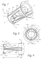
Fig. 7 shows a perspective view of another embodiment of a payout tube. -
Fig. 8 shows a front elevation view of the payout tube ofFig. 7 . -
Fig. 9 shows a side elevation view of the payout tube ofFig. 7 . -
Fig. 10A shows a schematic side view of the payout tube ofFig. 1 in a payout hole of a wound figure-eight coil. -
Fig. 10B shows a schematic side view of the payout tube ofFig. 7 in a payout hole of another wound figure-eight coil, showing a reduction in width of the coil compared to the coil inFig. 10A . -
Fig. 10C shows a front view of the arrangement shown inFig. 10B . -
Fig. 11A shows a front view of a package of filamentary material using the payout tube ofFig. 1 . -
Fig. 11B shows a front view of a package of filamentary material using the payout tube ofFig. 7 . - The embodiments shown in
Figures 1-6 ,10A and11A and described below do not fall within the scope of the claimed invention. -
Fig. 1 shows apayout tube 100 in accordance with an aspect of the disclosure, which does not fall within the scope of the claimed invention. Thepayout tube 100 may be made from various materials, included plastic or pulp paper. Thepayout tube 100 has anouter end 102 and aninner end 104. As used herein, "inner" and "outer" refer to location of theends payout tube 100 is inserted in a package including a coil of wound filamentary material. That is, when thepayout tube 100 is inserted into a coil, theinner end 108 will be located in a space defined by the coil (i.e., interior of the coil), while theouter end 106 will be located outside (exterior) the coil. In preferred embodiments, the coil is a coil of filamentary material wound in a figure-eight configuration, such as described inU.S. Patents 6,702,213 and6,341,741 . - The
payout tube 100 includes aflange 106 at theouter end 102, and an elongatedtubular body 108 that extends longitudinally from theflange 106, along an axis A-A, to theinner end 104. Theflange 106 is coaxial with thetubular body 108. In the embodiment shown, thetubular body 102 has atapered wall 108a of uniform thickness, which may be about 0.045 inch (~0.11 cm). - As shown in
Figs. 1, 2 , and3 , theflange 106 extends radially outwardly from thebody 108. Theflange 106 has an inner diameter that defines anexit opening 110 through which filamentary material passes during payout. In one embodiment, the diameter Dfi (Fig. 5 ) of theexit opening 110 may be between 3.5 inches and 4 inches (~8.9 cm and ~10.2 cm), and theflange 106 may have an outer diameter, Dfo (Fig. 6 ) of between 4.3 inches and 4.8 inches (~10.9 cm and ~12.2 cm). In the embodiment shown, the outer diameter Dfo of theflange 106 is approximately 4.6 inches (~11.7 cm). - At the
inner end 104 of thepayout tube 100, thewall 108a of thetubular body 108 is rounded radially inwardly towards the axis A-A forming a half-round profile oredge 112, shown in greater detail inFig. 4 . The radius of the profile may be between 0.20 inch and 0.30 inch (~0.51 cm and ~0.76 cm). In the embodiment shown inFigs 1 to 4 , the radius of the profile is approximately 0.25 inch (~0.64 cm). The half-round edge 112 defines an inlet opening 114 (Fig. 3 ) at theinner end 106 of thepayout tube 100. In one embodiment, theinlet opening 114 may have an inlet diameter, Di (Fig. 6 ), of between 1.75 inch and 2.25 inches (~4.4 cm and ~5.7 cm). In the embodiment ofpayout tube 100 shown inFigs. 1 to 6 , the inlet diameter, Di, is approximately 1.92 inch (~4.9 cm). The inlet diameter, Di, is noticeably smaller (about 32% smaller) than the inner diameter Db (Fig. 5 ) of thetubular body 108 at thebase 118 of therounded edge 112, which in the embodiment of thepayout tube 100 is approximately 2.82 inches (~7.2 cm). - During payout of filamentary material from a coil of filamentary material wound in a figure-eight configuration, the
payout tube 100 sits in an opening formed in the coil and filamentary material enters thepayout tube 100 through theinlet opening 114 and exits theexit opening 110. Therounded edge 112 with a desired radius of between 0.20 and 0.30 inch (~0.51 cm and ~0.76 cm) atend 104 provides a smooth edge against which filamentary material contacts thepayout tube 100 as it enters theinlet opening 114. Because of the desired radius, therounded edge 112 facilitates an easier sliding of the filamentary material along theedge 112 during payout. For example, some portions of filamentary material payed out may have small kinks or irregularities at locations along their length. Such kinks or irregularities may slide more easily over therounded edge 112 of the desired radius than if the edge is sharper as in the prior art. - Standoffs 116 (
Figs. 2 ,3, and 4 ) may be located on an inner side of thewall 108a of thetubular body 108 and may be located at or near theinner end 104. In the example embodiment shown, threestandoffs 116 are included and are spaced circumferentially 120 degrees apart from one another about axis A-A. While threestandoffs 116 are shown in the embodiment of thepayout tube 100, more or fewer standoffs may be present. Thestandoffs 116 maintain a certain amount of axial spacing betweenadjacent payout tubes 100 when they are stacked or nested one inside one another. This spacing can mitigate adjacent stackedpayout tubes 100 from "sticking" or otherwise tightly wedging themselves together when stacked. -
Figs. 5 and 6 show additional details of thepayout tube 100 ofFig. 1 , which does not fall within the scope of the claimed invention. Thepayout tube 100 may have an axial length, L (Fig. 5 ), of about 6 inches (~15.2 cm). A taper angle Θ (Fig. 5 ) of thebody 108 is relatively shallow and may, in one embodiment, be less than 10 degrees. In the embodiment shown, the taper angle, Θ, of thebody 108 is approximately 7 degrees. Also, in embodiments, thetubular body 108 tapers down to an outer diameter at thebase 118 of therounded edge 112 of about 2.75 to 3.25 inches (~7 cm and ~8.3 cm). In the embodiment shown inFig. 5 , thetubular body 108 tapers to an outer diameter of approximately 2.9 inches (~7.4 cm) at thebase 118 of therounded edge 112. - Turning now to
Figs. 7 to 10C , anotherpayout tube 200 is seen. Thepayout tube 200 may be formed from plastic or pulp paper and may have a uniform wall thickness.Payout tube 200 may have a roundededge 212, which is the same asedge 112 ofpayout tube 100, i.e., having a radius of between 0.20 and 0.30 inches (~0.51 cm and ~0.76 cm) such as 0.25 inch (~0.64 cm). The overall dimensions of the payout tube 200 (e.g., length, inlet and outlet diameters, and taper angle) may be the substantially the same as those forpayout tube 100, although thepayout tube 200 differs frompayout tube 100 in other ways. In particular, thepayout tube 200 includes an outertubular ring 202 having aflange 206, an innertubular ring 204 having therounded edge 212 or profile, andelongated pillars 208 connecting the outer and inner tubular rings 202 and 204 in coaxially spaced relation along axis B-B. Two diametricallyopposed pillars 208 are shown in the embodiment inFig. 7 , although additional spaced pillars may be used in other embodiments. - The
pillars 208 are stiffened by substantially "V" shaped stiffeningribs 208a, which protrude along the outer surfaces of thepillars 208, as shown inFig. 7 . A corresponding substantially V-shape profile is indented on the inside surfaces of thepillars 208 so that a uniform wall thickness is maintained. Theribs 208a extend axially between theflange 206 and therounded edge 212, though theribs 208a need not terminate at either theflange 206 or therounded edge 212. In the example embodiment, the indent of the substantially V-shaped profile extends to theflange 206 such that aninner edge 206a (Figs. 7 and 9 ) of theflange 206 has diametrically opposed substantially V-shapedindents 206b (Figs. 7 and 9 ) corresponding to the indented profiles on the inside surfaces of thepillars 208. The substantially V-shaped profile of theribs 208a is wider towards theflange 206 than towards therounded edge 212. Theribs 208a have acentral ridge 208b which is rounded and not sharp. Thisrounded ridge 208b is intended to prevent any pinching or kinking of filamentary material in contact with theridge 208b. It is noted that the substantially V-shaped tapered stiffening ribs do not taper to a point at the inner end, but rather have a narrow non-tapered end as seen best inFig. 9 . - In addition to stiffening the
payout tube 200, theribs 208a also provide a keyed locating feature for inserting thepayout tube 200 into a payout hole of a figure-eight wound coil of filamentary material. Specifically, a wound coil that has been wound in a figure-eight configuration may have a diamond-shaped payout hole. The protruding V-shapedribs 208a on the exterior sides of thepillars 208 are configured to vertically align with upper and lower vertices of a diamond shaped payout hole. - Standoffs 216 (
Figs. 7, 8, and 9 ) may also be located on an inner side of theinner ring 204 and may be located at or near therounded edge 212. In the example embodiment shown, threestandoffs 216 are included and are spaced circumferentially 120 degrees apart from one another about axis B-B. While threestandoffs 216 are shown in the embodiment of thepayout tube 200, more or fewer standoffs may be present. Thestandoffs 216 maintain a certain amount of axial spacing betweenadjacent payout tubes 200 when they are stacked or nested inside one another. This separation can mitigate adjacent stackedpayout tubes 200 from "sticking" or otherwise tightly wedging themselves together when stacked. - When the
payout tube 200 is disposed in a payout hole of a coil of filamentary material wound in a figure-eight configuration, the filamentary material will typically compress into spaces between theinner ring 204, theouter ring 202, and thepillars 208. Filamentary material located in these spaces, when eventually paid out, will have to move out of the spaces and contact an edge 220 (Figs. 7 and 9 ) before being drawn through inlet opening 214 (Fig 7 ). Theedge 220 is comprised of a compound curve having a convex portion 220a and aconcave portion 220b. The convex portion 220a is located at a radially outermost location ofpillar 208, while theconcave portion 220b is located radially closer to axis B-B, as shown inFig. 9 . Theedge 220 is thus gently curved and smooth so that the filamentary material in the spaces between inner andouter rings pillars 208 can more easily slide along theedge 220 without kinking or getting caught on theedge 220. - As previously mentioned, some of the dimensions of the
payout tube 200 may be the same as the dimensions as thepayout tube 100. For example, theinner edge 206a of theflange 206 defines anexit opening 210 having a diameter Dfi (Fig. 7 ), which may have the same dimension as the diameter Dfi of the exit opening 110 of thepayout tube 100. Also, the inner andouter rings Fig. 9 ) of thepayout tube 200 that may have the same dimension as the taper angle Θ of thepayout tube 100. Therounded edge 212 defines aninlet opening 214 having a diameter Di (Fig. 9 ), which may have the same dimension as the diameter Di of the inlet opening 114 of thepayout tube 100. An outer diameter Db (Fig. 7 ) of theinner ring 204 at thebase 218 of therounded edge 212 may have the same dimension as the outer diameter Db of thetubular body 108 at thebase 118 of therounded edge 112 of thepayout tube 100. Also, thepayout tube 200 has a length L (Fig. 9 ) measured along axis B-B, which may have the same dimension as the length L of thepayout tube 100. - The
payout tube 200, when compared topayout tube 100, eliminates a significant amount of material from thebody 108.Fig. 10A (which is not within the scope of the claimed invention) showspayout tube 100 inserted into acoil 1000 offilamentary material 1010 wound in a figure-eight configuration. As shown inFig. 10A , because thewall 108a ofbody 108 is solid, thefilamentary material 1010 cannot be located in the space occupied by thepayout tube 100. As a result, the coil 1000 (and its box) is dimensioned to be wider than necessary to accommodate the width of thepayout tube 100. In contrast, as shown inFigs. 10B and 10C , when thetube 200 is inserted into acoil 2000 offilamentary material 2010, the coil width can be narrower than the width of the coil shown inFig. 10A , because filamentary 2010 material can be located in the open spaces around thepillars 208 of thepayout tube 200 which spaces are otherwise closed forpayout tube 100. Indeed, when using thetube 200, thecoil 2000 can compress significantly, and thus reduce the overall width of the coil and its box. The reduced dimensions of the box can allow for a 30 to 40 percent increase in shipping density depending on the size of the box. For example, a typical box that holds a figure-eight wound coil of Category 6A cable has dimensions of 16 inches x 16 inches x 10 inches (~41 cm x 41 cm x 25 cm), and such coil can accommodate thepayout tube 100 described above. The use ofpayout tube 200 allows for a coil (and box) of smaller dimension so that an additional 2 to 4 boxes per layer to be placed on a shipping pallet as compared to the example box. - Turning to
Figs. 11A and 11B ,packages 1102, 1102' are provided includingboxes 1100, 1100' containing figure-eight wound filamentary material (not shown) into whichpayout tubes Fig. 11A (which is not within the scope of the claimed invention), the filamentary material (not shown) is packaged in abox 1100 having a length that is 14 to 15 inches (~36 cm and ~38 cm), a width that is 9 to 10 inches (~23 cm and ~25 cm), and height that is 14 to 15 inches (~36 cm and ~38 cm). Boxes of other dimensions may be utilized. Thebox 1100 may be constructed as described inU.S. Patents 6,341,741 and6,702,213 .Fig. 11A shows thebox 1100 defining apayout hole 1104 in a rectangular side of thebox 1100, and thepayout tube 100. The coil defines a payout hole that aligns with thepayout hole 1104 of thebox 1100 and with the axis A-A (Figs. 1 ,3 , and5 ) of thepayout tube 100. The inner end of thepayout tube 100 is disposed in an interior of the coil and theflange 106 is located adjacent to the rectangular side of the box 1100 (e.g., captured between two flaps of the rectangular side). -
Fig. 11B shows a box 1100' (Fig. 11B ) having a length that is 14 to 15 inches (~36 cm and ~38 cm), a width that is 9 to 10 inches (~23 cm and ~25 cm), and height that is 14 to 15 inches (~36 cm and ~38 cm). Boxes of other dimensions (e.g., smaller as noted above) may be utilized. The box 1100' may be constructed as described inU.S. Patents 6,341,741 and6,702,213 . Box 1100' defines a payout hole 1104' in a rectangular side of the box 1100' into whichpayout tube 200 extends. Figure-eight wound filamentary material (not shown) contained inside the box defines a payout hole that aligns with the payout hole 1104' of the box 1100' and with the axis B-B (Figs. 7 and 9 ) of thepayout tube 200. The inner end of thepayout tube 200 is disposed in an interior of the coil and theflange 206 is located adjacent to the rectangular side of the box 1100' (e.g., captured between two flaps of the rectangular side). - There have been described and illustrated herein several embodiments of a payout tube. While particular embodiments of the invention have been described, it is not intended that the invention be limited thereto, as the scope of the invention is solely defined by the appended claims. In addition, while particular types of materials for the construction of the payout tube have been disclosed, it will be understood that other suitable materials can be used. For example, and not by way of limitation, metal.
Claims (14)
- A payout tube (100,200) for facilitating payout of filamentary material from a coil of filamentary material wound in a figure-eight configuration and defining a payout hole, the payout hole extending from an inner wind of the coil to an outer wind of the coil, the payout tube comprising:an outer ring (202) having a flange (106, 206) at an outer end (102) of the payout tube, the outer ring centered about a longitudinal axis;an inner ring (204) having a rounded edge (112, 212) at an inner end of the payout tube, wherein the inner ring is aligned coaxially with the outer ring and is spaced longitudinally from the outer ring; anda plurality of pillars (208) spaced from one another and extending longitudinally from the outer ring to the inner ring.
- The payout tube according to claim 1, wherein:
the rounded edge has a radius of between 0.51 cm and 0.76 cm (0.20 inch and 0.30 inch). - The payout tube according to claim 1, wherein:
each pillar of the plurality of pillars includes a stiffener. - The payout tube according to claim 3, wherein:
the stiffener has a substantially V-shaped profile that protrudes from an exterior side of the pillar and is indented on an interior side of the pillar. - The payout tube according to claim 4, wherein:
the substantially V-shaped profile has a width that tapers down from the outer ring to the inner ring. - The payout tube according to claim 1, wherein:
the plurality of pillars includes two diametrically opposed pillars. - The payout tube according to claim 1, further comprising:
a plurality of standoffs located on an inner side of the inner ring and at or near the rounded edge, wherein the plurality of standoffs are configured to maintain axial spacing between the payout tube and a second payout tube when the second payout tube is stacked or nested inside the payout tube. - A package (1102, 1102') of filamentary material wound in a figure-eight configuration, the package comprising:a box or packaging defining a payout hole (1104);a coil of filamentary material wound into a figure-eight configuration defining a diamond shaped payout hole in alignment with the payout hole of the box or packaging; anda payout tube (100, 200) having an inner end and an outer end, the inner end disposed in an interior of the coil and the outer end extending outwardly from the payout hole of the coil, the payout tube having a flange (106, 206) at the outer end and having a rounded edge (112, 212) at the inner end, the rounded edge having a radius of between 0.51 cm and 0.76 cm (0.20 inch and 0.30 inch);wherein the payout tube is a payout tube according to claim 1.
- The package of claim 8, wherein:
the payout tube further includes a tubular body (108) extending from the flange to the inner end of the payout tube, the tubular body being tapered towards the inner end of the payout tube, and wherein the tubular body is centered about a longitudinal axis coaxial with the flange. - The package of claim 8, wherein:
the flange defines an exit opening for passage of the filamentary material, wherein the exit opening has a diameter of between 8.9 cm and 10.2 cm (3.5 inches and 4 inches). - The package of claim 8, wherein:
each pillar of the plurality of pillars includes a stiffener having a substantially V-shaped profile protruding from an exterior side of the pillar, wherein the substantially V-shaped profile aligns with a vertex of the diamond shaped payout hole. - The package of claim 8, wherein:
the box or packaging is a box having a length of 36 to 38 cm (14 to 15 inches), a width of 23 to 25 cm (9 to 10 inches), and height of 36 to 38 cm (14 to 15 inches), the box having six sides with the payout hole defined in one side of the box. - The package according to claim 8, wherein:
the payout tube includes two diametrically opposed pillars. - The package according to claim 8, wherein:
a plurality of standoffs are located on an inner side of a wall (108a) of the tubular body and at or near the inner end, wherein the plurality of standoffs are configured to maintain axial spacing between the payout tube and a second payout tube when the second payout tube is stacked or nested inside the payout tube.
Applications Claiming Priority (2)
| Application Number | Priority Date | Filing Date | Title |
|---|---|---|---|
| US16/352,344 US10815097B2 (en) | 2019-03-13 | 2019-03-13 | Payout tubes |
| PCT/US2020/019859 WO2020185404A1 (en) | 2019-03-13 | 2020-02-26 | Payout tubes |
Publications (4)
| Publication Number | Publication Date |
|---|---|
| EP3938306A1 EP3938306A1 (en) | 2022-01-19 |
| EP3938306A4 EP3938306A4 (en) | 2022-09-21 |
| EP3938306B1 true EP3938306B1 (en) | 2025-04-02 |
| EP3938306C0 EP3938306C0 (en) | 2025-04-02 |
Family
ID=72424922
Family Applications (1)
| Application Number | Title | Priority Date | Filing Date |
|---|---|---|---|
| EP20769258.3A Active EP3938306B1 (en) | 2019-03-13 | 2020-02-26 | Payout tubes |
Country Status (13)
| Country | Link |
|---|---|
| US (1) | US10815097B2 (en) |
| EP (1) | EP3938306B1 (en) |
| JP (2) | JP7644714B2 (en) |
| KR (1) | KR102805653B1 (en) |
| CN (1) | CN113784905B (en) |
| AU (1) | AU2020236344B2 (en) |
| BR (1) | BR112021017967A2 (en) |
| CA (1) | CA3132871A1 (en) |
| HU (1) | HUE071863T2 (en) |
| MX (1) | MX2021011085A (en) |
| PL (1) | PL3938306T3 (en) |
| UA (1) | UA130494C2 (en) |
| WO (1) | WO2020185404A1 (en) |
Families Citing this family (3)
| Publication number | Priority date | Publication date | Assignee | Title |
|---|---|---|---|---|
| USD938807S1 (en) * | 2019-06-05 | 2021-12-21 | Reelex Packaging Solutions, Inc. | Payout tube |
| USD938806S1 (en) * | 2019-06-05 | 2021-12-21 | Reelex Packaging Solutions, Inc | Payout tube |
| WO2025150382A1 (en) * | 2024-01-09 | 2025-07-17 | 出光ユニテック株式会社 | Tape wound body, method for conveying tape, method for manufacturing film equipped with tape, and method for manufacturing bag-like container equipped with tape |
Family Cites Families (25)
| Publication number | Priority date | Publication date | Assignee | Title |
|---|---|---|---|---|
| US3693784A (en) | 1971-01-08 | 1972-09-26 | William T Holmes | Wire package |
| GB1340314A (en) * | 1972-04-10 | 1973-12-12 | Windings Inc | Package of elongate flexible material and method and apparatus for producing such a package |
| US4009845A (en) | 1975-09-24 | 1977-03-01 | Santucci Kenneth E | Unreel reinforcer for dispensing wire |
| US4057203A (en) | 1976-05-14 | 1977-11-08 | Windings, Inc. | Package of flexible material with oval payout tube |
| JPH0513981U (en) * | 1991-07-26 | 1993-02-23 | 晃栄電設株式会社 | Bundling drawer container |
| JPH0627828U (en) * | 1992-09-22 | 1994-04-12 | 三菱マテリアル株式会社 | Entanglement prevention jig when pulling out the winding wire |
| JPH0645962U (en) * | 1992-11-24 | 1994-06-24 | タツタ電線株式会社 | Stranded wire inclusion guide |
| US5520347A (en) * | 1994-06-10 | 1996-05-28 | At&T Corp. | One-piece Reelex payout tube |
| SE507675C2 (en) * | 1996-01-03 | 1998-07-06 | Sahlins Maskin Ab | Method of manufacturing a package for an elongated flexible member wound into a roll form |
| US5810272A (en) * | 1996-03-28 | 1998-09-22 | Widings, Inc. | Snap-on tube and locking collar for guiding filamentary material through a wall panel of a container containing wound filamentary material |
| JPH11255426A (en) * | 1998-03-11 | 1999-09-21 | Sumitomo Wiring Syst Ltd | Wire bundle presser body and unwinding device using it |
| US6109554A (en) * | 1998-09-21 | 2000-08-29 | Windings, Inc. | Combined fiber containers and payout tubes and plastic payout tubes |
| US6341741B1 (en) | 1998-09-21 | 2002-01-29 | Windings, Inc. | Molded fiber and plastic tubes |
| US6328238B1 (en) * | 1999-10-28 | 2001-12-11 | Avaya Technology Corp. | Cable pay-out tube |
| US6702213B2 (en) | 2000-07-24 | 2004-03-09 | Frank W. Kotzur | Molded fiber and plastic tubes |
| ES2224868B1 (en) * | 2003-07-18 | 2007-12-16 | Filflex, S.L. | NEW SEALING SYSTEM THROUGH ELASTIC JOINT OF THREADED JOINTS IN PIPES FOR FLUID DRIVING AND APPLICATOR DEVICE FOR THE SAME. |
| US20050224615A1 (en) * | 2004-04-01 | 2005-10-13 | Miller Lisa K | Flexible cable container payout tube |
| US8136681B2 (en) * | 2009-01-15 | 2012-03-20 | Southwire Company | Stackable stems |
| US9254984B2 (en) * | 2010-12-16 | 2016-02-09 | Illinois Tool Works Inc. | Welding wire feeder with improved wire guide |
| US8985497B2 (en) | 2011-12-22 | 2015-03-24 | Stratasys, Inc. | Consumable assembly with payout tube for additive manufacturing system |
| US10538379B2 (en) * | 2014-03-11 | 2020-01-21 | Lincoln Global, Inc. | Welding wire coil package |
| US9776826B2 (en) * | 2014-10-14 | 2017-10-03 | Reelex Packaging Solutions, Inc. | Locking ring and packaging for dispensing wound material from a container |
| US9771238B2 (en) | 2015-08-14 | 2017-09-26 | Reelex Packaging Solutions, Inc. | Coil package payout tube assembly |
| US10710835B2 (en) * | 2016-12-28 | 2020-07-14 | Ademco Inc. | Collar retention system for packaging device for dispensing elongated flexible material |
| US10207890B2 (en) * | 2017-05-19 | 2019-02-19 | Reelex Packaging Solutions, Inc. | Apparatus and method for winding coil |
-
2019
- 2019-03-13 US US16/352,344 patent/US10815097B2/en active Active
-
2020
- 2020-02-26 HU HUE20769258A patent/HUE071863T2/en unknown
- 2020-02-26 BR BR112021017967A patent/BR112021017967A2/en unknown
- 2020-02-26 UA UAA202105755A patent/UA130494C2/en unknown
- 2020-02-26 WO PCT/US2020/019859 patent/WO2020185404A1/en not_active Ceased
- 2020-02-26 PL PL20769258.3T patent/PL3938306T3/en unknown
- 2020-02-26 KR KR1020217032506A patent/KR102805653B1/en active Active
- 2020-02-26 JP JP2021554698A patent/JP7644714B2/en active Active
- 2020-02-26 CN CN202080035553.4A patent/CN113784905B/en active Active
- 2020-02-26 AU AU2020236344A patent/AU2020236344B2/en active Active
- 2020-02-26 EP EP20769258.3A patent/EP3938306B1/en active Active
- 2020-02-26 MX MX2021011085A patent/MX2021011085A/en unknown
- 2020-02-26 CA CA3132871A patent/CA3132871A1/en active Pending
-
2024
- 2024-10-25 JP JP2024188041A patent/JP2025010209A/en not_active Withdrawn
Also Published As
| Publication number | Publication date |
|---|---|
| WO2020185404A1 (en) | 2020-09-17 |
| MX2021011085A (en) | 2021-10-22 |
| EP3938306A1 (en) | 2022-01-19 |
| BR112021017967A2 (en) | 2021-11-23 |
| CN113784905B (en) | 2023-10-31 |
| KR102805653B1 (en) | 2025-05-13 |
| AU2020236344A1 (en) | 2021-10-07 |
| HUE071863T2 (en) | 2025-09-28 |
| KR20210138046A (en) | 2021-11-18 |
| EP3938306A4 (en) | 2022-09-21 |
| JP7644714B2 (en) | 2025-03-12 |
| PL3938306T3 (en) | 2025-08-04 |
| CN113784905A (en) | 2021-12-10 |
| UA130494C2 (en) | 2026-03-04 |
| JP2025010209A (en) | 2025-01-20 |
| AU2020236344B2 (en) | 2025-04-17 |
| EP3938306C0 (en) | 2025-04-02 |
| US10815097B2 (en) | 2020-10-27 |
| JP2022524813A (en) | 2022-05-10 |
| US20200290841A1 (en) | 2020-09-17 |
| CA3132871A1 (en) | 2020-09-17 |
Similar Documents
| Publication | Publication Date | Title |
|---|---|---|
| EP0992446B1 (en) | A payout tube | |
| US4160533A (en) | Container with octagonal insert and corner payout | |
| AU2020236344B2 (en) | Payout tubes | |
| US4274607A (en) | Guide device for use in elongate filament dispensing package and the like | |
| JP2593851B2 (en) | Apparatus for storing extra length light guides | |
| CN101925432B (en) | Welding wire guide ring | |
| JPS604105B2 (en) | Dispensing support device for bundles of bendable material | |
| EP0701959A1 (en) | One piece reelex pay-out tube | |
| US4367853A (en) | Guide and support members for unwinding flexible material from a wound package | |
| US9776826B2 (en) | Locking ring and packaging for dispensing wound material from a container | |
| US20030075639A1 (en) | Molded fiber and plastic tubes | |
| CN102341208A (en) | Welding wire dispensing equipment for packaged welding wire | |
| JP2022524813A5 (en) | ||
| TWI851701B (en) | Payout tubes and package of filamentary material | |
| RU2788483C1 (en) | Tubular mandrel for unwinding and packing of fibrous material wound in eight-shaped configurations | |
| US20050224615A1 (en) | Flexible cable container payout tube | |
| US5979811A (en) | Cable payout tube | |
| RU2397937C2 (en) | Method of winding turns of material onto reel | |
| EP4603438A1 (en) | Spool having flange with tie-off feature | |
| CA1071605A (en) | Tube for inner end feedout of flexible material and package utilizing the same | |
| MXPA99008654A (en) | Fiber containers and combined river tubes and plastic tubes from arri | |
| GB1584213A (en) | Payout tube with replaceable inserts | |
| HK1059427A (en) | Container for coil of filamentary material |
Legal Events
| Date | Code | Title | Description |
|---|---|---|---|
| STAA | Information on the status of an ep patent application or granted ep patent |
Free format text: STATUS: THE INTERNATIONAL PUBLICATION HAS BEEN MADE |
|
| PUAI | Public reference made under article 153(3) epc to a published international application that has entered the european phase |
Free format text: ORIGINAL CODE: 0009012 |
|
| STAA | Information on the status of an ep patent application or granted ep patent |
Free format text: STATUS: REQUEST FOR EXAMINATION WAS MADE |
|
| 17P | Request for examination filed |
Effective date: 20210910 |
|
| AK | Designated contracting states |
Kind code of ref document: A1 Designated state(s): AL AT BE BG CH CY CZ DE DK EE ES FI FR GB GR HR HU IE IS IT LI LT LU LV MC MK MT NL NO PL PT RO RS SE SI SK SM TR |
|
| DAV | Request for validation of the european patent (deleted) | ||
| DAX | Request for extension of the european patent (deleted) | ||
| A4 | Supplementary search report drawn up and despatched |
Effective date: 20220824 |
|
| RIC1 | Information provided on ipc code assigned before grant |
Ipc: B65H 49/08 20060101ALI20220818BHEP Ipc: B65H 57/18 20060101ALI20220818BHEP Ipc: B65H 57/12 20060101ALI20220818BHEP Ipc: B65H 55/04 20060101AFI20220818BHEP |
|
| RIC1 | Information provided on ipc code assigned before grant |
Ipc: B65H 49/08 20060101ALI20221004BHEP Ipc: B65H 57/18 20060101ALI20221004BHEP Ipc: B65H 57/12 20060101ALI20221004BHEP Ipc: B65H 55/04 20060101AFI20221004BHEP |
|
| STAA | Information on the status of an ep patent application or granted ep patent |
Free format text: STATUS: EXAMINATION IS IN PROGRESS |
|
| 17Q | First examination report despatched |
Effective date: 20240213 |
|
| GRAP | Despatch of communication of intention to grant a patent |
Free format text: ORIGINAL CODE: EPIDOSNIGR1 |
|
| STAA | Information on the status of an ep patent application or granted ep patent |
Free format text: STATUS: GRANT OF PATENT IS INTENDED |
|
| INTG | Intention to grant announced |
Effective date: 20241017 |
|
| GRAS | Grant fee paid |
Free format text: ORIGINAL CODE: EPIDOSNIGR3 |
|
| GRAA | (expected) grant |
Free format text: ORIGINAL CODE: 0009210 |
|
| STAA | Information on the status of an ep patent application or granted ep patent |
Free format text: STATUS: THE PATENT HAS BEEN GRANTED |
|
| AK | Designated contracting states |
Kind code of ref document: B1 Designated state(s): AL AT BE BG CH CY CZ DE DK EE ES FI FR GB GR HR HU IE IS IT LI LT LU LV MC MK MT NL NO PL PT RO RS SE SI SK SM TR |
|
| REG | Reference to a national code |
Ref country code: GB Ref legal event code: FG4D |
|
| REG | Reference to a national code |
Ref country code: CH Ref legal event code: EP |
|
| REG | Reference to a national code |
Ref country code: IE Ref legal event code: FG4D |
|
| REG | Reference to a national code |
Ref country code: DE Ref legal event code: R096 Ref document number: 602020048773 Country of ref document: DE |
|
| U01 | Request for unitary effect filed |
Effective date: 20250430 |
|
| U07 | Unitary effect registered |
Designated state(s): AT BE BG DE DK EE FI FR IT LT LU LV MT NL PT RO SE SI Effective date: 20250512 |
|
| REG | Reference to a national code |
Ref country code: GR Ref legal event code: EP Ref document number: 20250401157 Country of ref document: GR Effective date: 20250707 Ref country code: SK Ref legal event code: T3 Ref document number: E 46653 Country of ref document: SK |
|
| REG | Reference to a national code |
Ref country code: HU Ref legal event code: AG4A Ref document number: E071863 Country of ref document: HU |
|
| PG25 | Lapsed in a contracting state [announced via postgrant information from national office to epo] |
Ref country code: ES Free format text: LAPSE BECAUSE OF FAILURE TO SUBMIT A TRANSLATION OF THE DESCRIPTION OR TO PAY THE FEE WITHIN THE PRESCRIBED TIME-LIMIT Effective date: 20250402 |
|
| PG25 | Lapsed in a contracting state [announced via postgrant information from national office to epo] |
Ref country code: NO Free format text: LAPSE BECAUSE OF FAILURE TO SUBMIT A TRANSLATION OF THE DESCRIPTION OR TO PAY THE FEE WITHIN THE PRESCRIBED TIME-LIMIT Effective date: 20250702 |
|
| PG25 | Lapsed in a contracting state [announced via postgrant information from national office to epo] |
Ref country code: HR Free format text: LAPSE BECAUSE OF FAILURE TO SUBMIT A TRANSLATION OF THE DESCRIPTION OR TO PAY THE FEE WITHIN THE PRESCRIBED TIME-LIMIT Effective date: 20250402 |
|
| PG25 | Lapsed in a contracting state [announced via postgrant information from national office to epo] |
Ref country code: RS Free format text: LAPSE BECAUSE OF FAILURE TO SUBMIT A TRANSLATION OF THE DESCRIPTION OR TO PAY THE FEE WITHIN THE PRESCRIBED TIME-LIMIT Effective date: 20250702 |
|
| PG25 | Lapsed in a contracting state [announced via postgrant information from national office to epo] |
Ref country code: IS Free format text: LAPSE BECAUSE OF FAILURE TO SUBMIT A TRANSLATION OF THE DESCRIPTION OR TO PAY THE FEE WITHIN THE PRESCRIBED TIME-LIMIT Effective date: 20250802 |
|
| PGFP | Annual fee paid to national office [announced via postgrant information from national office to epo] |
Ref country code: GB Payment date: 20251222 Year of fee payment: 7 |
|
| PG25 | Lapsed in a contracting state [announced via postgrant information from national office to epo] |
Ref country code: SM Free format text: LAPSE BECAUSE OF FAILURE TO SUBMIT A TRANSLATION OF THE DESCRIPTION OR TO PAY THE FEE WITHIN THE PRESCRIBED TIME-LIMIT Effective date: 20250402 |
|
| PGFP | Annual fee paid to national office [announced via postgrant information from national office to epo] |
Ref country code: GR Payment date: 20251223 Year of fee payment: 7 |
|
| PGFP | Annual fee paid to national office [announced via postgrant information from national office to epo] |
Ref country code: CZ Payment date: 20251222 Year of fee payment: 7 |
|
| PGFP | Annual fee paid to national office [announced via postgrant information from national office to epo] |
Ref country code: PL Payment date: 20251219 Year of fee payment: 7 |
|
| PGFP | Annual fee paid to national office [announced via postgrant information from national office to epo] |
Ref country code: SK Payment date: 20251222 Year of fee payment: 7 |
|
| U20 | Renewal fee for the european patent with unitary effect paid |
Year of fee payment: 7 Effective date: 20251223 |
|
| PLBE | No opposition filed within time limit |
Free format text: ORIGINAL CODE: 0009261 |
|
| STAA | Information on the status of an ep patent application or granted ep patent |
Free format text: STATUS: NO OPPOSITION FILED WITHIN TIME LIMIT |
|
| REG | Reference to a national code |
Ref country code: CH Ref legal event code: L10 Free format text: ST27 STATUS EVENT CODE: U-0-0-L10-L00 (AS PROVIDED BY THE NATIONAL OFFICE) Effective date: 20260211 |
|
| 26N | No opposition filed |
Effective date: 20260105 |
|
| PGFP | Annual fee paid to national office [announced via postgrant information from national office to epo] |
Ref country code: HU Payment date: 20260102 Year of fee payment: 7 |
|
| PGFP | Annual fee paid to national office [announced via postgrant information from national office to epo] |
Ref country code: IE Payment date: 20260120 Year of fee payment: 7 |
|
| PGFP | Annual fee paid to national office [announced via postgrant information from national office to epo] |
Ref country code: TR Payment date: 20260102 Year of fee payment: 7 |