EP3937538A1 - Procédé de détermination de longueur d'informations de réponse de rétroaction et produit associé - Google Patents
Procédé de détermination de longueur d'informations de réponse de rétroaction et produit associé Download PDFInfo
- Publication number
- EP3937538A1 EP3937538A1 EP21195034.0A EP21195034A EP3937538A1 EP 3937538 A1 EP3937538 A1 EP 3937538A1 EP 21195034 A EP21195034 A EP 21195034A EP 3937538 A1 EP3937538 A1 EP 3937538A1
- Authority
- EP
- European Patent Office
- Prior art keywords
- time unit
- response information
- feedback response
- index
- transmission delay
- Prior art date
- Legal status (The legal status is an assumption and is not a legal conclusion. Google has not performed a legal analysis and makes no representation as to the accuracy of the status listed.)
- Pending
Links
- 230000004044 response Effects 0.000 title claims abstract description 123
- 238000000034 method Methods 0.000 title claims abstract description 53
- 230000005540 biological transmission Effects 0.000 claims abstract description 154
- 238000012545 processing Methods 0.000 claims description 27
- 230000011664 signaling Effects 0.000 abstract description 28
- 230000008901 benefit Effects 0.000 abstract description 4
- 230000006870 function Effects 0.000 description 20
- 238000004891 communication Methods 0.000 description 16
- 238000010586 diagram Methods 0.000 description 13
- 238000004590 computer program Methods 0.000 description 11
- 238000007726 management method Methods 0.000 description 4
- 101000741965 Homo sapiens Inactive tyrosine-protein kinase PRAG1 Proteins 0.000 description 3
- 102100038659 Inactive tyrosine-protein kinase PRAG1 Human genes 0.000 description 3
- 238000013500 data storage Methods 0.000 description 3
- 230000007613 environmental effect Effects 0.000 description 3
- 230000008569 process Effects 0.000 description 3
- 102100036409 Activated CDC42 kinase 1 Human genes 0.000 description 2
- 238000004422 calculation algorithm Methods 0.000 description 2
- 238000004364 calculation method Methods 0.000 description 2
- 230000000694 effects Effects 0.000 description 2
- 238000005516 engineering process Methods 0.000 description 2
- 238000010295 mobile communication Methods 0.000 description 2
- 230000005236 sound signal Effects 0.000 description 2
- 230000001133 acceleration Effects 0.000 description 1
- 230000002776 aggregation Effects 0.000 description 1
- 238000004220 aggregation Methods 0.000 description 1
- 230000009286 beneficial effect Effects 0.000 description 1
- 230000003111 delayed effect Effects 0.000 description 1
- 238000013461 design Methods 0.000 description 1
- 238000007599 discharging Methods 0.000 description 1
- 230000005484 gravity Effects 0.000 description 1
- 230000003993 interaction Effects 0.000 description 1
- 239000004973 liquid crystal related substance Substances 0.000 description 1
- 230000007774 longterm Effects 0.000 description 1
- 238000012986 modification Methods 0.000 description 1
- 230000004048 modification Effects 0.000 description 1
- 238000012544 monitoring process Methods 0.000 description 1
- 230000003287 optical effect Effects 0.000 description 1
- 239000013307 optical fiber Substances 0.000 description 1
- 239000004065 semiconductor Substances 0.000 description 1
- 239000007787 solid Substances 0.000 description 1
- 230000003068 static effect Effects 0.000 description 1
Images


Classifications
-
- H—ELECTRICITY
- H04—ELECTRIC COMMUNICATION TECHNIQUE
- H04L—TRANSMISSION OF DIGITAL INFORMATION, e.g. TELEGRAPHIC COMMUNICATION
- H04L1/00—Arrangements for detecting or preventing errors in the information received
- H04L1/12—Arrangements for detecting or preventing errors in the information received by using return channel
- H04L1/16—Arrangements for detecting or preventing errors in the information received by using return channel in which the return channel carries supervisory signals, e.g. repetition request signals
- H04L1/18—Automatic repetition systems, e.g. Van Duuren systems
- H04L1/1829—Arrangements specially adapted for the receiver end
- H04L1/1854—Scheduling and prioritising arrangements
-
- H—ELECTRICITY
- H04—ELECTRIC COMMUNICATION TECHNIQUE
- H04L—TRANSMISSION OF DIGITAL INFORMATION, e.g. TELEGRAPHIC COMMUNICATION
- H04L1/00—Arrangements for detecting or preventing errors in the information received
- H04L1/12—Arrangements for detecting or preventing errors in the information received by using return channel
- H04L1/16—Arrangements for detecting or preventing errors in the information received by using return channel in which the return channel carries supervisory signals, e.g. repetition request signals
- H04L1/1607—Details of the supervisory signal
-
- H—ELECTRICITY
- H04—ELECTRIC COMMUNICATION TECHNIQUE
- H04L—TRANSMISSION OF DIGITAL INFORMATION, e.g. TELEGRAPHIC COMMUNICATION
- H04L1/00—Arrangements for detecting or preventing errors in the information received
- H04L1/12—Arrangements for detecting or preventing errors in the information received by using return channel
- H04L1/16—Arrangements for detecting or preventing errors in the information received by using return channel in which the return channel carries supervisory signals, e.g. repetition request signals
- H04L1/18—Automatic repetition systems, e.g. Van Duuren systems
- H04L1/1812—Hybrid protocols; Hybrid automatic repeat request [HARQ]
-
- H—ELECTRICITY
- H04—ELECTRIC COMMUNICATION TECHNIQUE
- H04L—TRANSMISSION OF DIGITAL INFORMATION, e.g. TELEGRAPHIC COMMUNICATION
- H04L1/00—Arrangements for detecting or preventing errors in the information received
- H04L1/12—Arrangements for detecting or preventing errors in the information received by using return channel
- H04L1/16—Arrangements for detecting or preventing errors in the information received by using return channel in which the return channel carries supervisory signals, e.g. repetition request signals
- H04L1/18—Automatic repetition systems, e.g. Van Duuren systems
- H04L1/1825—Adaptation of specific ARQ protocol parameters according to transmission conditions
-
- H—ELECTRICITY
- H04—ELECTRIC COMMUNICATION TECHNIQUE
- H04L—TRANSMISSION OF DIGITAL INFORMATION, e.g. TELEGRAPHIC COMMUNICATION
- H04L1/00—Arrangements for detecting or preventing errors in the information received
- H04L1/12—Arrangements for detecting or preventing errors in the information received by using return channel
- H04L1/16—Arrangements for detecting or preventing errors in the information received by using return channel in which the return channel carries supervisory signals, e.g. repetition request signals
- H04L1/18—Automatic repetition systems, e.g. Van Duuren systems
- H04L1/1829—Arrangements specially adapted for the receiver end
- H04L1/1864—ARQ related signaling
-
- H—ELECTRICITY
- H04—ELECTRIC COMMUNICATION TECHNIQUE
- H04L—TRANSMISSION OF DIGITAL INFORMATION, e.g. TELEGRAPHIC COMMUNICATION
- H04L1/00—Arrangements for detecting or preventing errors in the information received
- H04L1/12—Arrangements for detecting or preventing errors in the information received by using return channel
- H04L1/16—Arrangements for detecting or preventing errors in the information received by using return channel in which the return channel carries supervisory signals, e.g. repetition request signals
- H04L1/18—Automatic repetition systems, e.g. Van Duuren systems
- H04L1/1867—Arrangements specially adapted for the transmitter end
- H04L1/1896—ARQ related signaling
-
- H—ELECTRICITY
- H04—ELECTRIC COMMUNICATION TECHNIQUE
- H04L—TRANSMISSION OF DIGITAL INFORMATION, e.g. TELEGRAPHIC COMMUNICATION
- H04L5/00—Arrangements affording multiple use of the transmission path
- H04L5/003—Arrangements for allocating sub-channels of the transmission path
- H04L5/0053—Allocation of signaling, i.e. of overhead other than pilot signals
- H04L5/0055—Physical resource allocation for ACK/NACK
-
- H—ELECTRICITY
- H04—ELECTRIC COMMUNICATION TECHNIQUE
- H04L—TRANSMISSION OF DIGITAL INFORMATION, e.g. TELEGRAPHIC COMMUNICATION
- H04L5/00—Arrangements affording multiple use of the transmission path
- H04L5/0091—Signaling for the administration of the divided path
- H04L5/0094—Indication of how sub-channels of the path are allocated
-
- H—ELECTRICITY
- H04—ELECTRIC COMMUNICATION TECHNIQUE
- H04W—WIRELESS COMMUNICATION NETWORKS
- H04W28/00—Network traffic management; Network resource management
- H04W28/02—Traffic management, e.g. flow control or congestion control
- H04W28/04—Error control
-
- H—ELECTRICITY
- H04—ELECTRIC COMMUNICATION TECHNIQUE
- H04W—WIRELESS COMMUNICATION NETWORKS
- H04W72/00—Local resource management
- H04W72/04—Wireless resource allocation
-
- H—ELECTRICITY
- H04—ELECTRIC COMMUNICATION TECHNIQUE
- H04W—WIRELESS COMMUNICATION NETWORKS
- H04W72/00—Local resource management
- H04W72/12—Wireless traffic scheduling
Definitions
- the disclosure relates to the technical field of communication, and more particularly to a method and device for determining feedback response information and a related product.
- Hybrid Automatic Repeat request integrates storage, retransmission requesting and merging demodulation. That is, a receiving party, in case of a decoding failure, stores received data and requests a sending party for data retransmission, and the receiving party combines retransmitted data with the previously received data and decode the combined data.
- a new radio (NR) system supports dynamic indication of HARQ timing.
- a length i.e., number of bits
- ACK Acknowledgement
- NACK Negative Acknowledgement
- Embodiments of the disclosure provide a method and device for determining feedback response information, which may implement multiplexing transmission of an ACK/NACK in an NR system.
- the embodiments of the disclosure provide a method for determining feedback response information, which includes the following operations.
- a terminal determines feedback response information transmitted on a third time unit according to a first time unit, a second time unit and a number of first type time units, herein a sum of an index of the first time unit and a number of time units corresponding to a maximum transmission delay is equal to an index of the third time unit, a sum of an index of the second time unit and a number of time units corresponding to a minimum transmission delay is equal to the index of the third time unit, and a first type time unit is a time unit, not used for physical downlink shared channel (PDSCH) transmission, between the first time unit and the second time unit.
- PDSCH physical downlink shared channel
- the embodiments of the disclosure provide a method for determining feedback response information, which includes the following operations.
- a network device determines feedback response information transmitted on a third time unit according to a first time unit, a second time unit and a number of first type time units, herein a sum of an index of the first time unit and a number of time units corresponding to a maximum transmission delay is equal to an index of the third time unit, a sum of an index of the second time unit and the number of time units corresponding to a minimum transmission delay is equal to the index of the third time unit, and a first type time unit is a time unit, not used for PDSCH transmission, between the first time unit and the second time unit.
- the embodiments of the disclosure provide a device for determining feedback response information, which includes a processing unit.
- the processing unit is configured to determine feedback response information transmitted on a third time unit according to a first time unit, a second time unit and a number of first type time units, herein a sum of an index of the first time unit and a number of time units corresponding to a maximum transmission delay is equal to an index of the third time unit, a sum of an index of the second time unit and the number of time units corresponding to a minimum transmission delay is equal to the index of the third time unit, and a first type time unit is a time unit, not used for PDSCH transmission, between the first time unit and the second time unit.
- the terminal receives the maximum transmission delay sent by a base station, calculates a length of the feedback response information to be transmitted according to the maximum transmission delay and sends the feedback response information with the length to the base station. Therefore, multiplexing transmission of an ACK/NACK within a transmission time unit may be supported by an NR system, and the advantage of supporting multiplexing transmission of the feedback response information in the NR system is achieved.
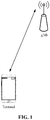
- FIG. 1 is a possible network architecture of an exemplary communication system according to an embodiment of the disclosure.
- the exemplary communication system may be a 5th-Generation (5G) NR communication system, and specifically includes a network-side device and a terminal.
- the terminal accesses a mobile communication network provided by the network-side device, the terminal may establish a communication connection with the network-side device through a radio link.
- a communication connection manner may be a single-connection manner or a dual-connection manner or a multi-connection manner.
- the network-side device may be a Long Term Evolution (LTE) base station or an NR Node B (NR-NB) (also called a gNB).
- LTE Long Term Evolution
- NR-NB NR Node B
- the multiple network-side devices may include a Master Cell Group (MCG) and Secondary Cell Groups (SCGs), data is transmitted back between the cell groups through backhauls, the MCG may be an NR-NB and the SCGs may be LTE base stations.
- MCG Master Cell Group
- SCGs Secondary Cell Groups
- a terminal involved in the embodiments of the disclosure may include various handheld devices, vehicle-mounted devices, wearable devices, computing devices or other processing devices connected to wireless modems, which have a wireless communication function, as well as User Equipment (UE), Mobile Stations (MSs), terminal devices and the like in various forms.
- UE User Equipment
- MSs Mobile Stations
- terminals the devices mentioned above are collectively referred to as terminals.
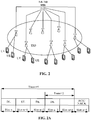
- FIG. 2 is a structure diagram of a 5G NR network.
- TRPs Transmission Reception Points
- terminals within a range of the one or more TRPs.
- a terminal needs to feed back to the gNB through HARQ whether the DL data is successfully received, i.e., the terminal is required to feed back a HARQ ACK/NACK to the gNB.
- FIG. 2A is a schematic diagram of a transmission time unit for HARQ timing in an NR system. There may be made such a hypothesis that the HARQ timing is indicated in a slot n. As illustrated in FIG.
- the HARQ timing may be five slots, and in the five slots, the slot n carries DL data for DL transmission, the slot n+1 carries UL data for UL transmission, the slot n+2 carries DL data, the slot n+3 carries DL data, the slot n+4 is empty and the slot n+5 is a slot through which the terminal feeds back an ACK/NACK to the gNB. Since both the slot n+2 and the slot n+3 carry the DL data, the ACK/NACK corresponding to the slot n+2 and the ACK/NACK corresponding to the slot n+3 are also required to be fed back.
- the gNB dynamically indicates that HARQ timing for the ACK/NACK corresponding to the slot n+2 is three slots and HARQ timing for the ACK/NACK corresponding to the slot n+3 is two slots, there are ACK/NACKs of thee slots for the slot n+5, namely multiplexing transmission of the ACKs/NACKs of the three slots is required to be performed in the slot n+5.
- the terminal in the NR system illustrated in FIG. 2 cannot implement multiplexing transmission of the ACKs/NACKs of the three slots in the slot n+5.
- FIG. 3 illustrates a method for determining a length of feedback response information according to an embodiment of the disclosure.
- the method is executed by a terminal. As illustrated in FIG. 3 , the method includes the following operations.
- the terminal receives configuration signaling sent by a network-side device (for example, a base station).
- the configuration signaling may include an indication about a maximum transmission delay for feedback response information.
- the configuration signaling in S301 may be transmitted by scheduling a PDSCH.
- the maximum transmission delay may be indicated in a DL grant for scheduling the PDSCH.
- a transmission time unit is, for example, a slot.
- the maximum transmission delay may be the number of slots.
- the maximum transmission delay may be, for example, k1, and then k1 is indicated in a DL grant, scheduling the PDSCH, of the slot n.
- the terminal dynamically determines an HARQ feedback timing.
- An implementation method for S302 may specifically be as follows.
- the terminal parses the configuration signaling to obtain the maximum transmission delay, a transmission time unit delayed by the maximum transmission delay from the first transmission time unit for reception of the configuration signaling is a transmission time unit for HARQ feedback response information.
- the transmission time unit is also, for example, a slot. If the configuration signaling is carried in a slot n for transmission and the maximum transmission delay corresponding to the configuration signaling is k1, the determined HARQ feedback timing is k1, and the transmission time unit for the HARQ feedback response information may be slot n+k1.
- the terminal determines a length (i.e., a total number of bits) of feedback response information to be transmitted according to the maximum transmission delay.
- the terminal determines the total number of bits of the feedback response information to be transmitted according to the maximum transmission delay and a minimum transmission delay.
- the terminal determines the total number of bits of the feedback response information to be transmitted according to a difference between the maximum transmission delay and the minimum transmission delay.
- the terminal determines the total number of bits of the feedback response information to be transmitted according to the maximum transmission delay, the minimum transmission delay and M non-DL .
- M non-DL is a value less than the maximum transmission delay.
- the terminal determines the total number of bits of the feedback response information to be transmitted according to a value obtained by subtracting the minimum transmission delay and M non-DL from the maximum transmission delay, and M non-DL is a value less than the maximum transmission delay.
- the terminal sends a message containing the feedback response information with the determined length of the feedback response information to be transmitted.
- An implementation method for the operation in S304 may specifically be as follows.
- the terminal sends the feedback response information subjected to a joint coding.
- the terminal sends the feedback response information through a physical channel.
- a base station when scheduling a PDSCH transmission, indicates the maximum transmission delay in a DL grant for scheduling the PDSCH of the first transmission time unit, and the terminal, after receiving the first transmission time unit, acquires the maximum transmission delay, calculates the length of the HARQ feedback response information according to the maximum transmission delay and sends the HARQ feedback response information with the length to the base station, so that multiplexing transmission of an ACK/NACK in a transmission time unit is supported in an NR system.
- the transmission time unit illustrated in FIG. 2A is sent in the NR illustrated in FIG. 2 .
- each transmission time unit includes two TBs. If the terminal successfully receives the slot n and the slot n+2 and the terminal does not receive the slot n+3, for the existing NR system, feedback response information in the slot n+5 may be 1111.
- the terminal In the existing NR system, if the terminal does not successfully receive the data of the slot, no corresponding response may be fed back, so that the terminal may not contain the HARQ feedback response information corresponding to the slot n+3 in the slot n+5, and the base station may not recognize, according to 1111, that the terminal does not receive the slot n+2 or the slot n+3. Therefore, the base station cannot accurately obtain the HARQ feedback response information of the terminal for subsequent operations, for example, data retransmission is unable to be performed according to the HARQ feedback response information.
- the terminal receives configuration information in the slot n, and the configuration information includes the maximum transmission delay of 5 slots.
- the terminal determines according to the maximum transmission delay that the total number of bits of the HARQ feedback response information is 6 (the specific method for determining the total number of bits may refer to the following descriptions and will not be elaborated herein), then the terminal sends the 6bit HARQ feedback response information in the slot n+5 and may specifically send 111100.
- the base station may learn according to allocation of slots for DL data that the slot n and the slot n+2 are successfully transmitted and the slot n+3 is failed to be transmitted, thereby achieving the advantage that multiplexing transmission of an ACK/NACK in a transmission time unit is supported in the NR system.
- an implementation method for the operation in S303 may specifically be as follows.
- N C * T max ⁇ T min
- T max may be the maximum transmission delay
- T min may be a nonnegative integer not greater than T max .
- Tmin may be the minimum transmission delay for transmission of the feedback response information by the terminal.
- Tmin may also be a parameter configured by the network-side device, and the parameter may be a fixed value.
- a value of Tmin may also be contained in the configuration signaling.
- C may be a maximum number of bits of feedback response information corresponding to a PDSCH, or C may be a set constant (i.e., a value specified in a protocol or a value predetermined by a manufacturer), or C may be a parameter configured by the network-side device.
- the maximum number of bits of the feedback response information corresponding to the PDSCH may specifically be: a maximum number of TBs carried in the PDSCH; or a maximum number of CB groups carried in the PDSCH.
- the maximum number of the TBs carried in a slot of the PDSCH may be 2 (the number is only for exemplary description and a specific value of the number is not limited in the disclosure), this does not mean that each slot includes two TBs, and in a practical application scenario, the slot may include one TB or no TB (for example, the slot n+4 illustrated in FIG. 2A ).
- the number of the CB groups carried in a slot of the PDSCH may be 4 (the number is only for exemplary description and a specific value of the number is not limited in the disclosure), and similarly, this also does not mean that each slot includes four CB groups. A method for determining a value of N will be described below with an example. Referring to FIG.
- the configuration signaling may be contained in the slot n, the maximum transmission delay in the configuration signaling is 4 slots, and the minimum transmission delay in the configuration signaling is 2 slots.
- the basic unit for the feedback response information is, for example, a TB.
- the basic unit for the feedback response information may also be a CB group, and the CB group includes at least one CB.
- the slot n+1 may be used to carry UL data, and for the slot n+1, no feedback response information is needed to be transmitted to the base station.
- the feedback response information corresponding to the slot n+1 may be filled with a specific numerical value (for example, 1 or 0), and the base station only needs to identify the feedback response information corresponding to the slot n and the slot n+2, and may discard or not process the feedback response information corresponding to the slot n+1.
- the implementation method for the operation in S303 may specifically be as follows.
- N C * T max ⁇ T min ⁇ M non ⁇ DL
- T min and M non-DL may be nonnegative integers, N is a nonnegative value, and meanings of C and T max may refer to the descriptions in the formula (1).
- M non-DL may be the number of all first-type time units between a transmission time unit Y-T max and a transmission time unit Y-T min
- a transmission time unit Y is a transmission time unit for transmission of the feedback response information.
- the first-type time unit may specifically include, but not limited to, one or any combination of a UL time unit, a time unit when the terminal performs no transmission of a physical shared channel and a time unit when the terminal does not monitor DL control signaling.
- another implementation manner may also be adopted to determine the length of the feedback response information according to the maximum transmission delay and the minimum transmission delay, or another implementation manner is adopted to determine the length of the feedback response information according to the maximum transmission delay, the minimum transmission delay and M non-DL .
- another implementation manner is adopted to determine the length of the feedback response information according to the maximum transmission delay, the minimum transmission delay and M non-DL .
- the basic unit for the feedback response information is, for example, a TB.
- the basic unit for the feedback response information may also be a CB group, and the CB group includes at least one CB.
- the above technical solution distinguishes whether the feedback response information between T max and T min is required to be fed back to the base station.
- the slot n+1 may be used carry UL data, and for the slot n+1, no feedback response information is needed to be transmitted to the base station. According to the technical solution, information of the slot n+1 is not fed back in the feedback response information.
- FIG. 3B illustrates a method for determining a length of feedback response information according to a specific implementation mode of the disclosure.
- a network device in the embodiment is, for example, a base station. The method is executed between a terminal and base station illustrated in FIG. 1 . Transmission time units between the terminal and the base station is illustrated in FIG. 3A . As illustrated in FIG. 3B , the method includes the following operations.
- the base station sends configuration signaling to the terminal in a slot n, and the configuration signaling includes an indication about a maximum transmission delay (four slots) of feedback response information.
- the terminal acquires the maximum transmission delay in the configuration signaling and dynamically determines an HARQ feedback timing to be four slots.
- the terminal sends the 2bit feedback response information to the base station in a slot n+4.
- the terminal calculates the total number of bits of the feedback response information and then sends the feedback response information having the total number of bits to the base station, so that multiplexing transmission of feedback response information for the slot n and a slot n+2 in the slot n+4 is implemented.
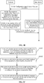
- FIG. 3C illustrates another method for determining a length of feedback response information.
- the method is executed by a network-side device, and the network-side device may be a base station illustrated in FIG. 1 or FIG. 2 .
- the method includes the following operations.
- the network-side device sends configuration signaling to a terminal, and the configuration signaling includes an indication about a maximum transmission delay for feedback response information.
- the network-side device determines an HARQ feedback timing dynamically determined by the terminal.
- the network-side device determines a total number of bits of feedback response information to be transmitted according to the maximum transmission delay.
- the network-side device determines the total number of bits of the feedback response information to be transmitted according to the maximum transmission delay and a minimum transmission delay.
- the network-side device determines the total number of bits of the feedback response information to be transmitted according to a difference between the maximum transmission delay and the minimum transmission delay.
- the network-side device determines the total number of bits of the feedback response information to be transmitted according to the maximum transmission delay, the minimum transmission delay and M non-DL .
- M non-DL is a value less than the maximum transmission delay.
- the network-side device determines the total number of bits of the feedback response information to be transmitted according to a value obtained by subtracting the minimum transmission delay and M non-DL from the maximum transmission delay, and M non-DL is a value less than the maximum transmission delay.
- the network-side device receives the feedback response information to be transmitted with the total number of bits from the terminal.
- the method of the embodiment illustrated in FIG. 3C supports implementation of the method of the embodiment illustrated in FIG. 3 , and thus has the advantage of supporting multiplexing transmission of an ACK/NACK of an NR system in a transmission time unit.
- the total number of bits N C ⁇ (T max -T min ).
- T max is the maximum transmission delay
- T min is a nonnegative integer less than T max
- C is a positive integer.
- the total number of bits N C ⁇ (T max -T min -M non-DL ).
- T max is the maximum transmission delay
- T min and M non-DL are nonnegative integers less than T max
- C is a positive integer.
- T min is the minimum transmission delay for transmission of feedback response information by the terminal, or T min is a parameter configured by the network-side device.
- C is a maximum number of bits of feedback response information corresponding to a PDSCH, or C is a set constant, or C is a parameter configured by the network-side device.
- M non-DL is the number of all first-type time units between a transmission time unit Y-T max and a transmission time unit Y-T min .
- the transmission time unit Y is a time unit for transmission of the feedback response information to be transmitted.
- the first-type time unit includes one or any combination of a UL time unit, a time unit when the terminal performs no transmission of a physical shared channel and a time unit when the terminal does not monitor DL control signaling.
- the maximum number of bits of the feedback response information corresponding to the PDSCH is: a maximum number of TBs carried in the PDSCH; or a maximum number of CB groups carried in the PDSCH.
- the operation that the network-side device receives the feedback response information to be transmitted with the total number of bits from the terminal may include one of the following actions.
- the network-side device receives from the terminal the feedback response information subjected to joint coding.
- the network-side device receives the feedback response information sent by the terminal through a physical channel.
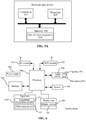
- FIG. 4 illustrates a device for determining a length of feedback response information.
- the device for determining the length of the feedback response information is configured in a terminal.
- the terminal includes a processing unit 401 and a transceiver unit 402 connected with the processing unit 401.
- the transceiver unit 402 is configured to receive configuration signaling sent by a network-side device.
- the configuration signaling includes an indication about a maximum transmission delay for feedback response information.
- the processing unit 401 is configured to dynamically determine an HARQ feedback timing and determine a total number of bits of feedback response information to be transmitted according to the maximum transmission delay.
- the transceiver unit 402 is configured to send the feedback response information to be transmitted with the total number of bits to the network-side device.
- the processing unit 401 is configured to: determine the total number of bits of the feedback response information to be transmitted according to the maximum transmission delay and a minimum transmission delay.
- the processing unit 401 is configured to: determine the total number of bits of the feedback response information to be transmitted according to a difference between the maximum transmission delay and the minimum transmission delay.
- the processing unit 401 is configured to: determine the total number of bits of the feedback response information to be transmitted according to the maximum transmission delay, the minimum transmission delay and M non-DL .
- M non-DL is a value less than the maximum transmission delay.
- the processing unit 401 is configured to: determine the total number of bits of the feedback response information to be transmitted according to a value obtained by subtracting the minimum transmission delay and M non-DL from the maximum transmission delay.
- M non-DL is a value less than the maximum transmission delay.
- T max is the maximum transmission delay
- T min is a nonnegative integer less than T max
- C is a positive integer.
- T max is the maximum transmission delay
- T min and M non-DL are nonnegative integers less than T max
- C is a positive integer.
- T min is the minimum transmission delay for transmission of feedback response information by the terminal, or T min is a parameter configured by the network-side device.
- M non-DL is the number of all first-type time units between a transmission time unit Y-T max and a transmission time unit Y-T min .
- the transmission time unit Y is a time unit including the feedback response information to be transmitted.
- the first-type time unit includes, but not limited to, one or any combination of a UL time unit, a time unit when the terminal performs no transmission of a physical shared channel and a time unit when the terminal does not monitor DL control signaling.
- C may specifically be as follows.
- C may be a maximum number of bits of feedback response information corresponding to a PDSCH, or C is a set constant, or C is a parameter configured by the network-side device.
- the maximum number of bits of the feedback response information corresponding to the PDSCH may be a maximum number of TBs carried in the PDSCH, or a maximum number of CB groups carried in the PDSCH.
- the transceiver unit 402 is configured to jointly code the feedback response information and send the coded feedback response information. Or the transceiver unit 402 is configured to send the feedback response information through a physical channel.
- FIG. 4A illustrates a network-side device, which includes a processing unit 408 and a transceiver 409 connected with the processing unit.
- the transceiver unit 408 is configured to send configuration signaling to a terminal.
- the configuration signaling includes an indication about a maximum transmission delay for feedback response information.
- the processing unit 409 is configured to determine an HARQ feedback timing dynamically determined by the terminal and determine a total number of bits of feedback response information to be transmitted according to the maximum transmission delay.
- the transceiver unit 408 is configured to receive the feedback response information to be transmitted with the total number of bits from the terminal.
- a calculation manner for the total number of bits may refer to descriptions in the embodiment illustrated in FIG. 3C , and will not be elaborated herein.
- An embodiment of the disclosure also provides a terminal.
- the terminal includes one or more processors 501, a memory 502, a transceiver 503 and one or more programs 504.
- the one or more programs are stored in the memory 502 and configured to be executed by the one or more processors 501.
- the programs include instructions configured to execute the operations executed by the terminal in the method provided by the embodiment illustrated in FIG. 3 or FIG. 3B .
- An embodiment of the disclosure also provides a network-side device.
- the network-side device includes one or more processors 505, a memory 506, a transceiver 507 and one or more programs 508.
- the one or more programs are stored in the memory 506 and configured to be executed by the one or more processors 505.
- the programs include instructions configured to execute the operations executed by the network device in the method provided by the embodiment illustrated in FIG. 3C or FIG. 3B .
- the processor may be a processor or a controller, for example, a Central Processing unit (CPU), a Digital Signal Processor (DSP), an Application Specific Integrated Circuit (ASIC), a Field Programmable Gate Array (FPGA) or another programmable logical device, transistor logical device, hardware component or any combination thereof.
- the processor may implement or execute various exemplary logical blocks, modules and circuits described in combination with the contents disclosed in the disclosure.
- the processor may also be a combination for realizing a calculation function, for example, including a combination of one or more microprocessors and a combination of a DSP and a microprocessor.
- the transceiver 503 may be a communication interface or an antenna.
- An embodiment of the disclosure also provides a computer-readable storage medium, which stores a computer program configured for electronic data exchange.
- the computer program enables a computer to execute the method executed by the terminal in the embodiment illustrated in FIG. 3 or FIG. 3B .
- the computer program enables the computer to execute the method executed by the network-side device in the embodiment illustrated in FIG. 3C or FIG. 3B .
- An embodiment of the disclosure also provides a computer program product.
- the computer program product includes a non-transitory computer-readable storage medium storing a computer program.
- the computer program may be operable to enable a computer to execute the method executed by the terminal in the embodiment illustrated in FIG. 3 or FIG. 3B .
- the computer program enables the computer to execute the method executed by the network-side device in the embodiment illustrated in FIG. 3C or FIG. 3B .
- the terminal and the network-side device include corresponding hardware structures and/or software modules executing each function.
- the units and algorithm operations of each example described in combination with the embodiments disclosed in the disclosure may be implemented by hardware or a combination of the hardware and computer software in the disclosure. Whether a certain function is executed by the hardware or in a manner of driving the hardware by the computer software depends on specific applications and design constraints of the technical solutions. Professionals may realize the described functions for each specific application by use of different methods, but such realization shall fall within the scope of the disclosure.
- each functional unit may be divided correspondingly to each function and two or more than two functions may also be integrated into a processing unit.
- the integrated unit may be implemented in a hardware form and may also be implemented in form of software program module. It is to be noted that division of the units in the embodiments of the disclosure is schematic and only is a logical function division and another division manner may be adopted during practical implementation.
- An embodiment of the disclosure also provides another terminal. As illustrated in FIG. 6 , for convenient description, only parts related to the embodiments of the disclosure are illustrated, and specific technical details which are undisclosed refer to parts of the method of the embodiments of the disclosure.
- the terminal may be any terminal device including a mobile phone, a tablet computer, a Personal Digital Assistant (PDA), a Point of Sales (POS), a vehicle-mounted computer and the like.
- the terminal is a mobile phone.
- FIG. 6 is a block diagram of part structure of a mobile phone related to a terminal according to an embodiment of the disclosure.
- the mobile phone includes components such as a Radio Frequency (RF) circuit 910, a memory 920, an input unit 930, a display unit 940, a sensor 950, an audio circuit 960, a Wireless Fidelity (Wi-Fi) module 970, a processor 980 and a power supply 990.
- RF Radio Frequency
- the RF circuit 910 may be configured to receive and send information.
- the RF circuit 910 usually includes, but not limited to, an antenna, at least one amplifier, a transceiver, a coupler, a Low Noise Amplifier (LNA), a duplexer and the like.
- the RF circuit 910 may also communicate with a network and another device through wireless communication.
- the wireless communication may adopt any communication standard or protocol, including, but not limited to, a Global System of Mobile communication (GSM), a General Packet Radio Service (GPRS), Code Division Multiple Access (CDMA), Wideband Code Division Multiple Access (WCDMA), LTE, an electronic mail, Short Messaging Service (SMS) and the like.
- GSM Global System of Mobile communication
- GPRS General Packet Radio Service
- CDMA Code Division Multiple Access
- WCDMA Wideband Code Division Multiple Access
- LTE Long Term Evolution
- SMS Short Messaging Service
- the memory 920 may be configured to store a software program and a module.
- the processor 980 operates the software program and module stored in the memory 920, thereby executing various function applications and data processing of the mobile phone.
- the memory 920 may mainly include a program storage region and a data storage region.
- the program storage region may store an operating system, an application program required by at least one function and the like.
- the data storage region may store data created according to use of the mobile phone and the like.
- the memory 920 may include a high-speed Random Access Memory (RAM) and may further include a nonvolatile memory, for example, at least one disk storage device, flash memory device or other volatile solid-state storage device.
- RAM Random Access Memory
- the input unit 930 may be configured to receive input digital or character information and generate key signal input related to user setting and function control of the mobile phone.
- the input unit 930 may include a fingerprint recognition module 931 and another input device 932.
- the fingerprint recognition module 931 may acquire fingerprint data of a user thereon.
- the input unit 930 may further include the other input device 932.
- the other input device 932 may include, but not limited to, one or more of a touch screen, a physical keyboard, a function key (for example, a volume control button and a switch button), a trackball, a mouse, a stick and the like.
- the display unit 940 may be configured to display information input by the user or information provided for the user and various menus of the mobile phone.
- the display unit 940 may include a display screen 941.
- the display screen 941 may be configured in form of Liquid Crystal Display (LCD) and Organic Light-Emitting Diode (OLED).
- LCD Liquid Crystal Display
- OLED Organic Light-Emitting Diode
- the fingerprint recognition module 931 and the display screen 941 realize input and output functions of the mobile phone as two independent components.
- the fingerprint recognition module 931 and the display screen 941 may be integrated to realize the input and play functions of the mobile phone.
- the mobile phone may further include at least one sensor 950, for example, a light sensor, a motion sensor and another sensor.
- the light sensor may include an environmental light sensor and a proximity sensor.
- the environmental light sensor may regulate brightness of the display screen 941 according to brightness of environmental light, and the proximity sensor may turn off the display screen 941 and/or backlight when the mobile phone is moved to an ear.
- An accelerometer sensor as a motion sensor may detect a magnitude of an acceleration in each direction (usually three axes), may detect a magnitude and direction of the gravity under a static condition, and may be configured for an application recognizing a posture of the mobile phone (for example, landscape and portrait switching, a related game and magnetometer posture calibration), a function related to vibration recognition and the like (for example, a pedometer and knocking).
- Other sensors for example, a gyroscope, a barometer, a hygrometer, a thermometer and an infrared sensor, which may be configured in the mobile phone, will not be elaborated herein.
- the audio circuit 960, a speaker 961, and a microphone 962 may provide audio interfaces between the user and the mobile phone.
- the audio circuit 960 may transmit an electric signal obtained by converting received audio data to the speaker 961, and the speaker 961 converts the electric signal into a sound signal for playing.
- the microphone 962 converts a collected sound signal into an electric signal
- the audio circuit 960 receives and converts the electric signal into audio data
- the audio data is processed by the playing processor 980 and sent to, for example, another mobile phone through the RF circuit 910, or the audio data is played to the memory 920 for further processing.
- Wi-Fi belongs to a short-distance wireless transmission technology.
- the mobile phone may help the user through the Wi-Fi module 970 to receive and send an electronic mail, browse a webpage, access streaming media and the like, and wireless wideband Internet access is provided for the user.
- the Wi-Fi module 970 is illustrated in FIG. 6 , it can be understood that it is not a necessary composition of the mobile phone and may completely be omitted according to a requirement without changing the scope of the essence of the disclosure.
- the processor 980 is a control center of the mobile phone, connects each part of the whole mobile phone by use of various interfaces and lines and executes various functions and data processing of the mobile phone by running or executing the software program and/or module stored in the memory 920 and calling data stored in the memory 920, thereby monitoring the whole mobile phone.
- the processor 980 may include one or more processing units.
- the processor 980 may integrate an application processor and a modulation and demodulation processor.
- the application processor mainly processes the operating system, a user interface, an application program and the like.
- the modulation and demodulation processor mainly processes wireless communication. It can be understood that the modulation and demodulation processor may also not be integrated into the processor 980.
- the mobile phone further includes the power supply 990 (e.g., battery) supplying power to each part (for example, a battery).
- the power supply may be logically connected with the processor 980 through a power management system, thereby realizing functions of charging and discharging management, power consumption management and the like through the power management system.
- the mobile phone may further include a camera, a Bluetooth module and the like, which will not be elaborated herein.
- the flow on a terminal side in each method may be implemented on the basis of the structure of the mobile phone.
- each functional unit may be implemented on the basis of the structure of the mobile phone.
- a software instruction may consist of a corresponding software module, and the software module may be stored in an RAM, a flash memory, a Read Only Memory (ROM), an Erasable Programmable ROM (EPROM), an Electrically EPROM (EEPROM), a register, a hard disk, a mobile hard disk, a Compact Disc-ROM (CD-ROM) or a storage medium in any other form well known in the field.
- An exemplary storage medium is coupled to the processor, thereby enabling the processor to read information from the storage medium and write information into the storage medium.
- the storage medium may also be a component of the processor.
- the processor and the storage medium may be located in an ASIC.
- the ASIC may be located in an access network device, a target network device or a core network device.
- the processor and the storage medium may also exist in the access network device, the target network device or the core network device as discrete components.
- the embodiments may be implemented completely or partially in form of computer program product.
- the computer program product includes one or more computer instructions.
- the computer may be a universal computer, a dedicated computer, a computer network or another programmable device.
- the computer instruction may be stored in a computer-readable storage medium or transmitted from one computer-readable storage medium to another computer-readable storage medium.
- the computer instruction may be transmitted from a website, computer, server or data center to another website, computer, server or data center in a wired (for example, coaxial cable, optical fiber and Digital Subscriber Line (DSL)) or wireless (for example, infrared, wireless and microwave) manner.
- the computer-readable storage medium may be any available medium accessible for the computer or a data storage device including such as a server and a data center integrated by one or more available media.
- the available medium may be a magnetic medium (for example, a floppy disk, a hard disk and a magnetic tape), an optical medium (for example, a Digital Video Disc (DVD)), a semiconductor medium (for example, a Solid State Disk (SSD)) or the like.
Landscapes
- Engineering & Computer Science (AREA)
- Signal Processing (AREA)
- Computer Networks & Wireless Communication (AREA)
- Mobile Radio Communication Systems (AREA)
- Detection And Prevention Of Errors In Transmission (AREA)
- Data Exchanges In Wide-Area Networks (AREA)
- Length Measuring Devices With Unspecified Measuring Means (AREA)
Applications Claiming Priority (3)
| Application Number | Priority Date | Filing Date | Title |
|---|---|---|---|
| PCT/CN2017/096656 WO2019028703A1 (fr) | 2017-08-09 | 2017-08-09 | Procédé de détermination de longueur d'informations de réponse de rétroaction et produit associé |
| EP18843899.8A EP3618494B1 (fr) | 2017-08-09 | 2018-04-03 | Procédé de détermination de longueur d'informations de réponse de rétroaction et produit associé |
| PCT/CN2018/081785 WO2019029173A1 (fr) | 2017-08-09 | 2018-04-03 | Procédé de détermination de longueur d'informations de réponse de rétroaction et produit associé |
Related Parent Applications (1)
| Application Number | Title | Priority Date | Filing Date |
|---|---|---|---|
| EP18843899.8A Division EP3618494B1 (fr) | 2017-08-09 | 2018-04-03 | Procédé de détermination de longueur d'informations de réponse de rétroaction et produit associé |
Publications (1)
| Publication Number | Publication Date |
|---|---|
| EP3937538A1 true EP3937538A1 (fr) | 2022-01-12 |
Family
ID=65273018
Family Applications (3)
| Application Number | Title | Priority Date | Filing Date |
|---|---|---|---|
| EP21195034.0A Pending EP3937538A1 (fr) | 2017-08-09 | 2018-04-03 | Procédé de détermination de longueur d'informations de réponse de rétroaction et produit associé |
| EP18843899.8A Active EP3618494B1 (fr) | 2017-08-09 | 2018-04-03 | Procédé de détermination de longueur d'informations de réponse de rétroaction et produit associé |
| EP18845148.8A Active EP3624377B1 (fr) | 2017-08-09 | 2018-05-04 | Procédé de détermination du nombre total de bits d'informations de réponse de rétroaction et produit associé |
Family Applications After (2)
| Application Number | Title | Priority Date | Filing Date |
|---|---|---|---|
| EP18843899.8A Active EP3618494B1 (fr) | 2017-08-09 | 2018-04-03 | Procédé de détermination de longueur d'informations de réponse de rétroaction et produit associé |
| EP18845148.8A Active EP3624377B1 (fr) | 2017-08-09 | 2018-05-04 | Procédé de détermination du nombre total de bits d'informations de réponse de rétroaction et produit associé |
Country Status (15)
| Country | Link |
|---|---|
| US (4) | US11233621B2 (fr) |
| EP (3) | EP3937538A1 (fr) |
| JP (1) | JP7125431B6 (fr) |
| KR (1) | KR20200035240A (fr) |
| CN (4) | CN111130711B (fr) |
| AU (1) | AU2018314361A1 (fr) |
| BR (1) | BR112019026949A2 (fr) |
| CA (1) | CA3066673C (fr) |
| CL (1) | CL2019003914A1 (fr) |
| ES (2) | ES2900497T3 (fr) |
| IL (1) | IL271334A (fr) |
| PH (1) | PH12019502716A1 (fr) |
| SG (1) | SG11201912237UA (fr) |
| TW (2) | TWI775917B (fr) |
| WO (2) | WO2019028703A1 (fr) |
Cited By (1)
| Publication number | Priority date | Publication date | Assignee | Title |
|---|---|---|---|---|
| US20220085957A1 (en) * | 2017-08-09 | 2022-03-17 | Guangdong Oppo Mobile Telecommunications Corp., Ltd. | Method for determining total number of bits of feedback response information and related product |
Families Citing this family (2)
| Publication number | Priority date | Publication date | Assignee | Title |
|---|---|---|---|---|
| WO2021229445A2 (fr) * | 2020-05-15 | 2021-11-18 | Lenovo (Singapore) Pte. Ltd. | Émission de signaux avec retards |
| US11609935B2 (en) * | 2020-07-16 | 2023-03-21 | Red Hat, Inc. | Managing configuration datasets from multiple, distinct computing systems |
Family Cites Families (58)
| Publication number | Priority date | Publication date | Assignee | Title |
|---|---|---|---|---|
| US7542421B2 (en) * | 2005-09-09 | 2009-06-02 | Tropos Networks | Adaptive control of transmission power and data rates of transmission links between access nodes of a mesh network |
| WO2007084065A2 (fr) * | 2006-01-18 | 2007-07-26 | Telefonaktiebolaget Lm Ericsson (Publ) | Procédé et configuration dans un système de télécommunications |
| EP1858190B1 (fr) * | 2006-05-16 | 2012-01-11 | Nokia Siemens Networks GmbH & Co. KG | Procédé pour la transmission des bitmaps ACK/NACK dans un procédé ARQ au sein d'un système conforme au edge |
| US8493873B2 (en) | 2007-06-18 | 2013-07-23 | Qualcomm Incorporated | Multiplexing of sounding signals in ACK and CQI channels |
| CN101547077B (zh) * | 2008-03-24 | 2011-07-20 | 鼎桥通信技术有限公司 | 一种传输ack/nack信息的方法 |
| CN101771502A (zh) * | 2009-01-07 | 2010-07-07 | 中兴通讯股份有限公司 | 一种信息复用的方法、系统和用户终端 |
| US8670396B2 (en) | 2009-09-29 | 2014-03-11 | Qualcomm Incorporated | Uplink control channel resource allocation for transmit diversity |
| CN102036305B (zh) | 2009-09-30 | 2014-05-07 | 华为技术有限公司 | 控制信息的发送和接收方法、装置和通信系统 |
| CN102647261B (zh) * | 2010-04-06 | 2014-10-22 | 电信科学技术研究院 | 调度信令发送及应答反馈的方法、系统和设备 |
| CN102237982B (zh) * | 2010-04-30 | 2013-11-06 | 电信科学技术研究院 | 一种载波聚合系统下ack/nak的传输方法和设备 |
| KR101797496B1 (ko) * | 2010-07-07 | 2017-12-12 | 엘지전자 주식회사 | 무선통신 시스템에서 제어정보의 전송 방법 및 장치 |
| CN101958775B (zh) * | 2010-09-30 | 2015-05-20 | 中兴通讯股份有限公司 | 确认信息的发送方法及用户设备 |
| CN102158326B (zh) * | 2011-05-20 | 2014-05-14 | 电信科学技术研究院 | Ack/nack反馈信息的传输方法和设备 |
| DK3930238T3 (da) | 2012-01-24 | 2023-11-27 | Interdigital Patent Holdings Inc | Systemer og fremgangsmåder til forbedret uplink-dækning |
| ES2569939T3 (es) * | 2012-05-10 | 2016-05-13 | Telefonaktiebolaget L M Ericsson (Publ) | Método y aparato para la señalización de petición de repetición automática híbrida para agregación de portadora |
| WO2014000221A1 (fr) | 2012-06-28 | 2014-01-03 | Nokia Corporation | Transmission flexible de signaux ack/nack de processus harq |
| CN103580825B (zh) * | 2012-08-03 | 2017-05-24 | 电信科学技术研究院 | Uci的传输方法和设备 |
| US9100935B2 (en) * | 2012-08-06 | 2015-08-04 | Innovative Sonic Corporation | Method and apparatus for time division duplex uplink-downlink configuration change in a wireless communication system |
| KR102261051B1 (ko) * | 2014-05-14 | 2021-06-04 | 삼성전자주식회사 | 무선통신 시스템에서 하이브리드 자동 재전송 요청 피드백 방법 및 장치 |
| JP6478304B2 (ja) * | 2015-01-30 | 2019-03-06 | 華為技術有限公司Huawei Technologies Co.,Ltd. | 通信システムおよび装置におけるフィードバック情報伝送方法 |
| JP6101311B2 (ja) | 2015-06-26 | 2017-03-22 | 株式会社Nttドコモ | ユーザ端末、無線基地局及び無線通信方法 |
| KR102108474B1 (ko) * | 2015-07-01 | 2020-05-08 | 엘지전자 주식회사 | 무선 통신 시스템에서 신호의 전송 방법 및 장치 |
| CN106452661B (zh) * | 2015-08-10 | 2020-05-22 | 中兴通讯股份有限公司 | 应答信息的传输方法、装置、基站及终端 |
| CN111147189B (zh) * | 2015-08-12 | 2021-03-23 | 华为技术有限公司 | 上行控制信息发送接收方法、装置及系统 |
| WO2017078782A1 (fr) * | 2015-11-03 | 2017-05-11 | Intel IP Corporation | Agencements de cycle harq flexibles |
| KR101982994B1 (ko) | 2016-01-26 | 2019-05-27 | 소니 주식회사 | 단말 장치, 기지국 장치 및 통신 방법 |
| WO2017131374A1 (fr) * | 2016-01-29 | 2017-08-03 | 주식회사 케이티 | Procédé de commande d'une harq de liaison descendante dans un système de communication sans fil et dispositif associé |
| US10873422B2 (en) | 2016-02-26 | 2020-12-22 | Lg Electronics Inc. | Method for executing HARQ in wireless communication system and device therefor |
| US10412620B2 (en) | 2016-04-01 | 2019-09-10 | Motorola Mobility Llc | Method and apparatus for scheduling uplink transmissions with reduced latency |
| CN107294646B (zh) * | 2016-04-01 | 2020-08-07 | 电信科学技术研究院 | 一种信息反馈方法、基站及终端 |
| CN107370576B (zh) * | 2016-05-12 | 2019-11-19 | 中国移动通信有限公司研究院 | 一种确定混合自动重传请求反馈时序的方法及装置 |
| US10595166B2 (en) * | 2016-07-18 | 2020-03-17 | Sharp Kabushiki Kaisha | Systems and methods for processing time reduction signaling |
| US10873437B2 (en) * | 2016-08-11 | 2020-12-22 | Sharp Kabushiki Kaisha | Systems and methods for frequency-division duplex transmission time interval operation |
| EP3535893A4 (fr) | 2016-11-04 | 2020-06-24 | Telefonaktiebolaget LM Ericsson (publ) | Procédés et dispositifs de retransmission de données |
| US20190342040A1 (en) | 2017-01-05 | 2019-11-07 | Nokia Technologies Oy | Scalable feedback reporting |
| CN108289015B (zh) * | 2017-01-09 | 2023-04-07 | 北京三星通信技术研究有限公司 | 发送harq-ack/nack的方法和设备及下行传输方法和设备 |
| WO2018143174A1 (fr) * | 2017-02-03 | 2018-08-09 | シャープ株式会社 | Dispositif station de base, dispositif terminal, et procédé de communication associé |
| EP4117214B8 (fr) * | 2017-02-06 | 2024-05-01 | Samsung Electronics Co., Ltd. | Procédé et équipement utilisateur (ue) de gestion de procédure harq pour plusieurs numérologies |
| CN114826490A (zh) * | 2017-05-05 | 2022-07-29 | 北京三星通信技术研究有限公司 | 调度方法、harq-ack反馈方法和相应设备 |
| CN116094681A (zh) * | 2017-06-02 | 2023-05-09 | 瑞典爱立信有限公司 | 用于反馈信令的大小指示 |
| WO2019028703A1 (fr) * | 2017-08-09 | 2019-02-14 | Oppo广东移动通信有限公司 | Procédé de détermination de longueur d'informations de réponse de rétroaction et produit associé |
| CN109391352B (zh) * | 2017-08-11 | 2021-12-10 | 华为技术有限公司 | 一种应答信息的传输方法、终端设备和网络设备 |
| CN109391422B (zh) * | 2017-08-11 | 2020-11-17 | 华为技术有限公司 | 一种反馈码本确定的方法及终端设备、网络设备 |
| CN117318905A (zh) * | 2017-09-29 | 2023-12-29 | 北京三星通信技术研究有限公司 | 上行传输方法和相应设备 |
| US11356987B2 (en) * | 2017-09-30 | 2022-06-07 | Samsung Electronics Co., Ltd. | Method and equipment for transmitting uplink control information and setting uplink time advance |
| WO2019075693A1 (fr) * | 2017-10-19 | 2019-04-25 | 华为技术有限公司 | Procédé et appareil pour traiter un livre de codes de rétroaction harq |
| US11246155B2 (en) * | 2018-03-27 | 2022-02-08 | Qualcomm Incorporated | Acknowledgement feedback in unlicensed new radio |
| CN110351018B (zh) * | 2018-04-04 | 2021-12-24 | 展讯通信(上海)有限公司 | Harq-ack反馈信息发送、接收方法及装置、存储介质、发送终端、接收终端 |
| CN113613331B (zh) * | 2018-09-28 | 2024-05-24 | 华为技术有限公司 | 一种通信方法、装置及设备 |
| CN111224754B (zh) * | 2018-11-23 | 2021-05-18 | 华为技术有限公司 | 通信方法、装置、设备、系统及存储介质 |
| CN111726204B (zh) * | 2019-03-22 | 2023-07-28 | 北京三星通信技术研究有限公司 | 半静态调度数据的harq-ack反馈的方法、ue、基站、设备及介质 |
| US11632195B2 (en) * | 2019-03-29 | 2023-04-18 | Huawei Technologies Co., Ltd. | Method for transmission of HARQ feedback in group common downlink control information |
| CN111770572B (zh) * | 2019-03-30 | 2023-08-04 | 华为技术有限公司 | 确定反馈信息的方法和通信装置 |
| KR20200145212A (ko) * | 2019-06-21 | 2020-12-30 | 삼성전자주식회사 | 통신 시스템에서 사이드링크 피드백 송수신 방법 및 장치 |
| CN110535609B (zh) * | 2019-08-02 | 2023-11-24 | 中兴通讯股份有限公司 | 目标参数的确定方法、通信节点和存储介质 |
| WO2021090298A1 (fr) * | 2019-11-08 | 2021-05-14 | Lenovo (Singapore) Pte. Ltd. | Procédé et appareil de gestion de la transmission d'un message de rétroaction |
| CN116210321A (zh) * | 2020-08-06 | 2023-06-02 | Oppo广东移动通信有限公司 | 半永久性调度的反馈方法、装置、设备和存储介质 |
| CN116056142A (zh) * | 2021-10-27 | 2023-05-02 | 上海朗帛通信技术有限公司 | 一种被用于无线通信的节点中的方法和装置 |
-
2017
- 2017-08-09 WO PCT/CN2017/096656 patent/WO2019028703A1/fr active Application Filing
-
2018
- 2018-04-03 CN CN201911348552.0A patent/CN111130711B/zh active Active
- 2018-04-03 BR BR112019026949-5A patent/BR112019026949A2/pt not_active IP Right Cessation
- 2018-04-03 AU AU2018314361A patent/AU2018314361A1/en not_active Abandoned
- 2018-04-03 KR KR1020197038199A patent/KR20200035240A/ko not_active Application Discontinuation
- 2018-04-03 CN CN201880032494.8A patent/CN110679177A/zh active Pending
- 2018-04-03 EP EP21195034.0A patent/EP3937538A1/fr active Pending
- 2018-04-03 JP JP2019570022A patent/JP7125431B6/ja active Active
- 2018-04-03 ES ES18843899T patent/ES2900497T3/es active Active
- 2018-04-03 SG SG11201912237UA patent/SG11201912237UA/en unknown
- 2018-04-03 EP EP18843899.8A patent/EP3618494B1/fr active Active
- 2018-04-03 WO PCT/CN2018/081785 patent/WO2019029173A1/fr active Application Filing
- 2018-04-03 CA CA3066673A patent/CA3066673C/fr active Active
- 2018-05-04 EP EP18845148.8A patent/EP3624377B1/fr active Active
- 2018-05-04 ES ES18845148T patent/ES2900340T3/es active Active
- 2018-05-04 CN CN201880033480.8A patent/CN110663210B/zh active Active
- 2018-05-04 US US16/619,431 patent/US11233621B2/en active Active
- 2018-05-04 CN CN201911342791.5A patent/CN111030782B/zh active Active
- 2018-08-09 TW TW107127887A patent/TWI775917B/zh active
- 2018-08-09 TW TW107127783A patent/TWI766080B/zh active
-
2019
- 2019-12-02 PH PH12019502716A patent/PH12019502716A1/en unknown
- 2019-12-04 US US16/703,286 patent/US20200336252A1/en not_active Abandoned
- 2019-12-11 IL IL271334A patent/IL271334A/en unknown
- 2019-12-30 CL CL2019003914A patent/CL2019003914A1/es unknown
-
2020
- 2020-09-15 US US17/021,700 patent/US11115171B2/en active Active
-
2021
- 2021-11-26 US US17/535,901 patent/US11855926B2/en active Active
Non-Patent Citations (2)
| Title |
|---|
| CATT: "HARQ and scheduling timing design for LTE sTTI", vol. RAN WG1, no. Hangzhou; 20170515 - 20170519, 14 May 2017 (2017-05-14), XP051272655, Retrieved from the Internet <URL:http://www.3gpp.org/ftp/Meetings_3GPP_SYNC/RAN1/Docs/> [retrieved on 20170514] * |
| ERICSSON: "On HARQ Codebook", vol. RAN WG1, no. Qingdao, China; 20170627 - 20170630, 17 June 2017 (2017-06-17), XP051305638, Retrieved from the Internet <URL:http://www.3gpp.org/ftp/tsg_ran/WG1_RL1/TSGR1_AH/NR_AH_1706/Docs/> [retrieved on 20170617] * |
Cited By (2)
| Publication number | Priority date | Publication date | Assignee | Title |
|---|---|---|---|---|
| US20220085957A1 (en) * | 2017-08-09 | 2022-03-17 | Guangdong Oppo Mobile Telecommunications Corp., Ltd. | Method for determining total number of bits of feedback response information and related product |
| US11855926B2 (en) * | 2017-08-09 | 2023-12-26 | Guangdong Oppo Mobile Telecommunications Corp., Ltd. | Method for determining total number of bits of feedback response information and related product |
Also Published As
Similar Documents
| Publication | Publication Date | Title |
|---|---|---|
| US11855926B2 (en) | Method for determining total number of bits of feedback response information and related product | |
| EP3493441B1 (fr) | Procédé d'indication de données et produit associé | |
| US11438108B2 (en) | Method for transmitting feedback response information and related product | |
| CA3062956A1 (fr) | Procede de commande de retransmission de donnees et produit associe | |
| RU2761970C9 (ru) | Способ определения длины информации отклика обратной связи и соответствующий продукт | |
| CN109964432B (zh) | 多比特信息复用传输方法及相关产品 | |
| WO2019029202A1 (fr) | Procédé de détermination du nombre total de bits d'informations de réponse de rétroaction et produit associé |
Legal Events
| Date | Code | Title | Description |
|---|---|---|---|
| PUAI | Public reference made under article 153(3) epc to a published international application that has entered the european phase |
Free format text: ORIGINAL CODE: 0009012 |
|
| STAA | Information on the status of an ep patent application or granted ep patent |
Free format text: STATUS: THE APPLICATION HAS BEEN PUBLISHED |
|
| AC | Divisional application: reference to earlier application |
Ref document number: 3618494 Country of ref document: EP Kind code of ref document: P |
|
| AK | Designated contracting states |
Kind code of ref document: A1 Designated state(s): AL AT BE BG CH CY CZ DE DK EE ES FI FR GB GR HR HU IE IS IT LI LT LU LV MC MK MT NL NO PL PT RO RS SE SI SK SM TR |
|
| B565 | Issuance of search results under rule 164(2) epc |
Effective date: 20211123 |
|
| STAA | Information on the status of an ep patent application or granted ep patent |
Free format text: STATUS: REQUEST FOR EXAMINATION WAS MADE |
|
| 17P | Request for examination filed |
Effective date: 20220712 |
|
| RBV | Designated contracting states (corrected) |
Designated state(s): AL AT BE BG CH CY CZ DE DK EE ES FI FR GB GR HR HU IE IS IT LI LT LU LV MC MK MT NL NO PL PT RO RS SE SI SK SM TR |