EP3937501A1 - Verfahren zur transformationsbasierten bildcodierung und vorrichtung dafür - Google Patents
Verfahren zur transformationsbasierten bildcodierung und vorrichtung dafür Download PDFInfo
- Publication number
- EP3937501A1 EP3937501A1 EP20777376.3A EP20777376A EP3937501A1 EP 3937501 A1 EP3937501 A1 EP 3937501A1 EP 20777376 A EP20777376 A EP 20777376A EP 3937501 A1 EP3937501 A1 EP 3937501A1
- Authority
- EP
- European Patent Office
- Prior art keywords
- transform
- index
- syntax element
- tree type
- information
- Prior art date
- Legal status (The legal status is an assumption and is not a legal conclusion. Google has not performed a legal analysis and makes no representation as to the accuracy of the status listed.)
- Granted
Links
Images


Classifications
-
- H—ELECTRICITY
- H04—ELECTRIC COMMUNICATION TECHNIQUE
- H04N—PICTORIAL COMMUNICATION, e.g. TELEVISION
- H04N19/00—Methods or arrangements for coding, decoding, compressing or decompressing digital video signals
- H04N19/10—Methods or arrangements for coding, decoding, compressing or decompressing digital video signals using adaptive coding
- H04N19/102—Methods or arrangements for coding, decoding, compressing or decompressing digital video signals using adaptive coding characterised by the element, parameter or selection affected or controlled by the adaptive coding
- H04N19/12—Selection from among a plurality of transforms or standards, e.g. selection between discrete cosine transform [DCT] and sub-band transform or selection between H.263 and H.264
-
- H—ELECTRICITY
- H04—ELECTRIC COMMUNICATION TECHNIQUE
- H04N—PICTORIAL COMMUNICATION, e.g. TELEVISION
- H04N19/00—Methods or arrangements for coding, decoding, compressing or decompressing digital video signals
- H04N19/10—Methods or arrangements for coding, decoding, compressing or decompressing digital video signals using adaptive coding
- H04N19/102—Methods or arrangements for coding, decoding, compressing or decompressing digital video signals using adaptive coding characterised by the element, parameter or selection affected or controlled by the adaptive coding
- H04N19/13—Adaptive entropy coding, e.g. adaptive variable length coding [AVLC] or context adaptive binary arithmetic coding [CABAC]
-
- H—ELECTRICITY
- H04—ELECTRIC COMMUNICATION TECHNIQUE
- H04N—PICTORIAL COMMUNICATION, e.g. TELEVISION
- H04N19/00—Methods or arrangements for coding, decoding, compressing or decompressing digital video signals
- H04N19/10—Methods or arrangements for coding, decoding, compressing or decompressing digital video signals using adaptive coding
- H04N19/102—Methods or arrangements for coding, decoding, compressing or decompressing digital video signals using adaptive coding characterised by the element, parameter or selection affected or controlled by the adaptive coding
- H04N19/132—Sampling, masking or truncation of coding units, e.g. adaptive resampling, frame skipping, frame interpolation or high-frequency transform coefficient masking
-
- H—ELECTRICITY
- H04—ELECTRIC COMMUNICATION TECHNIQUE
- H04N—PICTORIAL COMMUNICATION, e.g. TELEVISION
- H04N19/00—Methods or arrangements for coding, decoding, compressing or decompressing digital video signals
- H04N19/10—Methods or arrangements for coding, decoding, compressing or decompressing digital video signals using adaptive coding
- H04N19/134—Methods or arrangements for coding, decoding, compressing or decompressing digital video signals using adaptive coding characterised by the element, parameter or criterion affecting or controlling the adaptive coding
- H04N19/157—Assigned coding mode, i.e. the coding mode being predefined or preselected to be further used for selection of another element or parameter
- H04N19/159—Prediction type, e.g. intra-frame, inter-frame or bidirectional frame prediction
-
- H—ELECTRICITY
- H04—ELECTRIC COMMUNICATION TECHNIQUE
- H04N—PICTORIAL COMMUNICATION, e.g. TELEVISION
- H04N19/00—Methods or arrangements for coding, decoding, compressing or decompressing digital video signals
- H04N19/10—Methods or arrangements for coding, decoding, compressing or decompressing digital video signals using adaptive coding
- H04N19/169—Methods or arrangements for coding, decoding, compressing or decompressing digital video signals using adaptive coding characterised by the coding unit, i.e. the structural portion or semantic portion of the video signal being the object or the subject of the adaptive coding
- H04N19/17—Methods or arrangements for coding, decoding, compressing or decompressing digital video signals using adaptive coding characterised by the coding unit, i.e. the structural portion or semantic portion of the video signal being the object or the subject of the adaptive coding the unit being an image region, e.g. an object
- H04N19/176—Methods or arrangements for coding, decoding, compressing or decompressing digital video signals using adaptive coding characterised by the coding unit, i.e. the structural portion or semantic portion of the video signal being the object or the subject of the adaptive coding the unit being an image region, e.g. an object the region being a block, e.g. a macroblock
-
- H—ELECTRICITY
- H04—ELECTRIC COMMUNICATION TECHNIQUE
- H04N—PICTORIAL COMMUNICATION, e.g. TELEVISION
- H04N19/00—Methods or arrangements for coding, decoding, compressing or decompressing digital video signals
- H04N19/10—Methods or arrangements for coding, decoding, compressing or decompressing digital video signals using adaptive coding
- H04N19/169—Methods or arrangements for coding, decoding, compressing or decompressing digital video signals using adaptive coding characterised by the coding unit, i.e. the structural portion or semantic portion of the video signal being the object or the subject of the adaptive coding
- H04N19/1887—Methods or arrangements for coding, decoding, compressing or decompressing digital video signals using adaptive coding characterised by the coding unit, i.e. the structural portion or semantic portion of the video signal being the object or the subject of the adaptive coding the unit being a variable length codeword
-
- H—ELECTRICITY
- H04—ELECTRIC COMMUNICATION TECHNIQUE
- H04N—PICTORIAL COMMUNICATION, e.g. TELEVISION
- H04N19/00—Methods or arrangements for coding, decoding, compressing or decompressing digital video signals
- H04N19/50—Methods or arrangements for coding, decoding, compressing or decompressing digital video signals using predictive coding
- H04N19/593—Methods or arrangements for coding, decoding, compressing or decompressing digital video signals using predictive coding involving spatial prediction techniques
-
- H—ELECTRICITY
- H04—ELECTRIC COMMUNICATION TECHNIQUE
- H04N—PICTORIAL COMMUNICATION, e.g. TELEVISION
- H04N19/00—Methods or arrangements for coding, decoding, compressing or decompressing digital video signals
- H04N19/60—Methods or arrangements for coding, decoding, compressing or decompressing digital video signals using transform coding
- H04N19/61—Methods or arrangements for coding, decoding, compressing or decompressing digital video signals using transform coding in combination with predictive coding
-
- H—ELECTRICITY
- H04—ELECTRIC COMMUNICATION TECHNIQUE
- H04N—PICTORIAL COMMUNICATION, e.g. TELEVISION
- H04N19/00—Methods or arrangements for coding, decoding, compressing or decompressing digital video signals
- H04N19/70—Methods or arrangements for coding, decoding, compressing or decompressing digital video signals characterised by syntax aspects related to video coding, e.g. related to compression standards
-
- H—ELECTRICITY
- H04—ELECTRIC COMMUNICATION TECHNIQUE
- H04N—PICTORIAL COMMUNICATION, e.g. TELEVISION
- H04N19/00—Methods or arrangements for coding, decoding, compressing or decompressing digital video signals
- H04N19/90—Methods or arrangements for coding, decoding, compressing or decompressing digital video signals using coding techniques not provided for in groups H04N19/10-H04N19/85, e.g. fractals
- H04N19/96—Tree coding, e.g. quad-tree coding
-
- H—ELECTRICITY
- H04—ELECTRIC COMMUNICATION TECHNIQUE
- H04N—PICTORIAL COMMUNICATION, e.g. TELEVISION
- H04N19/00—Methods or arrangements for coding, decoding, compressing or decompressing digital video signals
- H04N19/10—Methods or arrangements for coding, decoding, compressing or decompressing digital video signals using adaptive coding
- H04N19/102—Methods or arrangements for coding, decoding, compressing or decompressing digital video signals using adaptive coding characterised by the element, parameter or selection affected or controlled by the adaptive coding
- H04N19/103—Selection of coding mode or of prediction mode
- H04N19/11—Selection of coding mode or of prediction mode among a plurality of spatial predictive coding modes
Definitions
- the present disclosure relates generally to an image coding technology and, more particularly, to an image coding method based on a transform in an image coding system and an apparatus therefor.
- VR virtual reality
- AR artificial reality
- hologram hologram
- a technical aspect of the present disclosure is to provide a method and an apparatus for increasing image coding efficiency.
- Another technical aspect of the present disclosure is to provide a method and an apparatus for increasing efficiency in transform index coding.
- Still another technical aspect of the present disclosure is to provide a method and an apparatus for coding a transform index based on a multiple transform technique.
- Yet another technical aspect of the present disclosure is to provide a method and an apparatus for coding the context of a transform index.
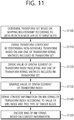
- an image decoding method performed by a decoding apparatus.
- the method may include performing an inverse primary transform and an inverse non-separable transform on a residual sample, wherein the inverse non-separable transform may be performed based on a transform index indicating a predetermined transform kernel matrix, the inverse primary transform may be performed based on a multiple transform selection (MTS) index indicating an MTS of a horizontal transform kernel and a vertical transform kernel, and a syntax element bin string of the transform index may be derived based on first context information, when a tree type of a partition structure of the target block is not a single tree type, and may be derived based on second context information, when the tree type is the single tree type.
- MTS multiple transform selection
- the syntax element bin string of the transform index may be derived based on the first context information when the MTS index has a value of 0 and the tree type is not the single tree type.
- the MTS index may be inferred to have a value of 0.
- the syntax element bin string of the transform index may be derived based on the first context information when the MTS index is not received and the tree type is not the single tree type.
- the transform kernel matrix may be included in a transform set determined based on a mapping relationship according to an intra prediction mode applied to the target block, and the transform index may indicate any one of whether the inverse non-separable transform is applied and the transform kernel matrix comprised in the transform set
- an image encoding method performed by an encoding apparatus.
- the method may include: deriving transform coefficients for a target block from residual samples based on a multiple transform selection (MTS) of a horizontal transform kernel and a vertical transform kernel; deriving modified transform coefficients from the transform coefficients based on a predetermined transform kernel matrix for a non-separable transform; and encoding an MTS index indicating the MTS or a transform index indicating the transform kernel matrix, wherein a syntax element bin string of the transform index may be derived based on first context information, when a tree type of a partition structure of the target block is not a single tree type, and may be derived based on second context information, when the tree type is the single tree type.
- MTS multiple transform selection
- a digital storage medium that stores image data including encoded image information and a bitstream generated according to an image encoding method performed by an encoding apparatus.
- a digital storage medium that stores image data including encoded image information and a bitstream to cause a decoding apparatus to perform the image decoding method.
- a technical aspect of the present disclosure may provide a method and an apparatus for coding a transform index based on a multiple transform technique.
- Another technical aspect of the present disclosure may provide a method and an apparatus for coding the context of a transform index.
- each component on the drawings described herein is illustrated independently for convenience of description as to characteristic functions different from each other, and however, it is not meant that each component is realized by a separate hardware or software.
- any two or more of these components may be combined to form a single component, and any single component may be divided into plural components.
- the embodiments in which components are combined and/or divided will belong to the scope of the patent right of the present disclosure as long as they do not depart from the essence of the present disclosure.
- VVC Very Video Coding
- HEVC High Efficiency Video Coding
- EVC essential video coding
- a video may mean a set of a series of images over time.
- a picture means a unit representing an image at a specific time zone
- a slice/tile is a unit constituting a part of the picture.
- the slice/tile may include one or more coding tree units (CTUs).
- CTUs coding tree units
- One picture may be constituted by one or more slices/tiles.
- One picture may be constituted by one or more tile groups.
- One tile group may include one or more tiles.
- a pixel or a pel may mean a smallest unit constituting one picture (or image). Also, 'sample' may be used as a term corresponding to a pixel.
- a sample may generally represent a pixel or a value of a pixel, and may represent only a pixel/pixel value of a luma component or only a pixel/pixel value of a chroma component. Alternatively, the sample may refer to a pixel value in the spatial domain, or when this pixel value is converted to the frequency domain, it may refer to a transform coefficient in the frequency domain.
- a unit may represent the basic unit of image processing.
- the unit may include at least one of a specific region and information related to the region.
- One unit may include one luma block and two chroma (e.g., cb, cr) blocks.
- the unit and a term such as a block, an area, or the like may be used in place of each other according to circumstances.
- an M ⁇ N block may include a set (or an array) of samples (or sample arrays) or transform coefficients consisting of M columns and N rows.
- the term “/” and “,” should be interpreted to indicate “and/or.”
- the expression “A/B” may mean “A and/or B.”
- A, B may mean “A and/or B.”
- A/B/C may mean “at least one of A, B, and/or C.”
- A/B/C may mean “at least one of A, B, and/or C.”
- the term “or” should be interpreted to indicate “and/or.”
- the expression “A or B” may include 1) only A, 2) only B, and/or 3) both A and B.
- the term “or” in this document should be interpreted to indicate "additionally or alternatively.”
- At least one of A and B may mean “only A”, “only B”, or “both A and B”.
- the expression “at least one of A or B” or “at least one of A and/or B” may be interpreted as "at least one of A and B”.
- At least one of A, B, and C may mean “only A”, “only B”, “only C”, or “any combination of A, B, and C”.
- at least one of A, B, or C or “at least one of A, B, and/or C” may mean “at least one of A, B, and C”.
- a parenthesis used in the present disclosure may mean “for example”. Specifically, when indicated as “prediction (intra prediction)”, it may mean that "intra prediction” is proposed as an example of “prediction”. In other words, the "prediction” of the present disclosure is not limited to “intra prediction”, and “intra prediction” may be proposed as an example of "prediction”. In addition, when indicated as “prediction (i.e., intra prediction)", it may also mean that "intra prediction” is proposed as an example of "prediction”.
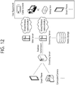
- FIG. 1 schematically illustrates an example of a video/image coding system to which the present disclosure is applicable.
- the video/image coding system may include a first device (source device) and a second device (receive device).
- the source device may deliver encoded video/image information or data in the form of a file or streaming to the receive device via a digital storage medium or network.
- the source device may include a video source, an encoding apparatus, and a transmitter.
- the receive device may include a receiver, a decoding apparatus, and a renderer.
- the encoding apparatus may be called a video/image encoding apparatus, and the decoding apparatus may be called a video/image decoding apparatus.
- the transmitter may be included in the encoding apparatus.
- the receiver may be included in the decoding apparatus.
- the renderer may include a display, and the display may be configured as a separate device or an external component.
- the video source may obtain a video/image through a process of capturing, synthesizing, or generating a video/image.
- the video source may include a video/image capture device and/or a video/image generating device.
- the video/image capture device may include, for example, one or more cameras, video/image archives including previously captured video/images, or the like.
- the video/image generating device may include, for example, a computer, a tablet and a smartphone, and may (electronically) generate a video/image.
- a virtual video/image may be generated through a computer or the like. In this case, the video/image capturing process may be replaced by a process of generating related data.
- the encoding apparatus may encode an input video/image.
- the encoding apparatus may perform a series of procedures such as prediction, transform, and quantization for compression and coding efficiency.
- the encoded data (encoded video/image information) may be output in the form of a bitstream.
- the transmitter may transmit the encoded video/image information or data output in the form of a bitstream to the receiver of the receive device through a digital storage medium or a network in the form of a file or streaming.
- the digital storage medium may include various storage mediums such as USB, SD, CD, DVD, Blu-ray, HDD, SSD, and the like.
- the transmitter may include an element for generating a media file through a predetermined file format, and may include an element for transmission through a broadcast/communication network.
- the receiver may receive/extract the bitstream and transmit the received/extracted bitstream to the decoding apparatus.
- the decoding apparatus may decode a video/image by performing a series of procedures such as dequantization, inverse transform, prediction, and the like corresponding to the operation of the encoding apparatus.
- the renderer may render the decoded video/image.
- the rendered video/image may be displayed through the display.
- FIG. 2 is a diagram schematically illustrating a configuration of a video/image encoding apparatus to which the present disclosure is applicable.
- the video encoding apparatus may include an image encoding apparatus.
- the encoding apparatus 200 may include an image partitioner 210, a predictor 220, a residual processor 230, an entropy encoder 240, an adder 250, a filter 260, and a memory 270.
- the predictor 220 may include an inter predictor 221 and an intra predictor 222.
- the residual processor 230 may include a transformer 232, a quantizer 233, a dequantizer 234, an inverse transformer 235.
- the residual processor 230 may further include a subtractor 231.
- the adder 250 may be called a reconstructor or reconstructed block generator.
- the image partitioner 210, the predictor 220, the residual processor 230, the entropy encoder 240, the adder 250, and the filter 260 may be constituted by one or more hardware components (e.g., encoder chipsets or processors) according to an embodiment.
- the memory 270 may include a decoded picture buffer (DPB), and may be constituted by a digital storage medium.
- the hardware component may further include the memory 270 as an internal/external component.
- the image partitioner 210 may partition an input image (or a picture or a frame) input to the encoding apparatus 200 into one or more processing units.
- the processing unit may be called a coding unit (CU).
- the coding unit may be recursively partitioned according to the Quad-tree binary-tree ternary-tree (QTBTTT) structure.
- QTBTTT Quad-tree binary-tree ternary-tree
- one coding unit may be divided into a plurality of coding units of a deeper depth based on the quad-tree structure, the binary-tree structure, and/or the ternary structure.
- the quad-tree structure may be applied first and the binary-tree structure and/or the ternary structure may be applied later.
- the binary-tree structure may be applied first.
- the coding procedure according to the present disclosure may be performed based on the final coding unit which is not further partitioned.
- the maximum coding unit may be used directly as a final coding unit based on coding efficiency according to the image characteristic.
- the coding unit may be recursively partitioned into coding units of a further deeper depth as needed, so that the coding unit of an optimal size may be used as a final coding unit.
- the coding procedure may include procedures such as prediction, transform, and reconstruction, which will be described later.
- the processing unit may further include a prediction unit (PU) or a transform unit (TU).
- the prediction unit and the transform unit may be split or partitioned from the above-described final coding unit.
- the prediction unit may be a unit of sample prediction
- the transform unit may be a unit for deriving a transform coefficient and/or a unit for deriving a residual signal from a transform coefficient.
- an M ⁇ N block may represent a set of samples or transform coefficients consisting of M columns and N rows.
- the sample may generally represent a pixel or a value of a pixel, and may represent only a pixel/pixel value of a luma component, or only a pixel/pixel value of a chroma component.
- the sample may be used as a term corresponding to a pixel or a pel of one picture (or image).
- the subtractor 231 subtractes a prediction signal (predicted block, prediction sample array) output from the inter predictor 221 or the intra predictor 222 from an input image signal (original block, original sample array) to generate a residual signal (residual block, residual sample array), and the generated residual signal is transmitted to the transformer 232.
- a unit which subtracts the prediction signal (predicted block, prediction sample array) from the input image signal (original block, original sample array) in the encoder 200 may be called the subtractor 231.
- the predictor may perform prediction on a processing target block (hereinafter, referred to as 'current block'), and may generate a predicted block including prediction samples for the current block.
- the predictor may determine whether intra prediction or inter prediction is applied on a current block or CU basis. As discussed later in the description of each prediction mode, the predictor may generate various information relating to prediction, such as prediction mode information, and transmit the generated information to the entropy encoder 240. The information on the prediction may be encoded in the entropy encoder 240 and output in the form of a bitstream.
- the intra predictor 222 may predict the current block by referring to samples in the current picture.
- the referred samples may be located in the neighbor of or apart from the current block according to the prediction mode.
- prediction modes may include a plurality of non-directional modes and a plurality of directional modes.
- the non-directional modes may include, for example, a DC mode and a planar mode.
- the directional mode may include, for example, 33 directional prediction modes or 65 directional prediction modes according to the degree of detail of the prediction direction. However, this is merely an example, and more or less directional prediction modes may be used depending on a setting.
- the intra predictor 222 may determine the prediction mode applied to the current block by using the prediction mode applied to the neighboring block.
- the inter predictor 221 may derive a predicted block for the current block based on a reference block (reference sample array) specified by a motion vector on a reference picture.
- the motion information may be predicted on a block, subblock, or sample basis based on correlation of motion information between the neighboring block and the current block.
- the motion information may include a motion vector and a reference picture index.
- the motion information may further include inter prediction direction (L0 prediction, L1 prediction, Bi prediction, etc.) information.
- the neighboring block may include a spatial neighboring block existing in the current picture and a temporal neighboring block existing in the reference picture.
- the reference picture including the reference block and the reference picture including the temporal neighboring block may be same to each other or different from each other.
- the temporal neighboring block may be called a collocated reference block, a collocated CU (colCU), and the like, and the reference picture including the temporal neighboring block may be called a collocated picture (colPic).
- the inter predictor 221 may configure a motion information candidate list based on neighboring blocks and generate information indicating which candidate is used to derive a motion vector and/or a reference picture index of the current block. Inter prediction may be performed based on various prediction modes. For example, in the case of a skip mode and a merge mode, the inter predictor 221 may use motion information of the neighboring block as motion information of the current block.
- the residual signal may not be transmitted.
- the motion vector of the neighboring block may be used as a motion vector predictor and the motion vector of the current block may be indicated by signaling a motion vector difference.
- the predictor 220 may generate a prediction signal based on various prediction methods. For example, the predictor may apply intra prediction or inter prediction for prediction on one block, and, as well, may apply intra prediction and inter prediction at the same time. This may be called combined inter and intra prediction (CIIP). Further, the predictor may be based on an intra block copy (IBC) prediction mode, or a palette mode in order to perform prediction on a block.
- IBC intra block copy
- the IBC prediction mode or palette mode may be used for content image/video coding of a game or the like, such as screen content coding (SCC).
- SCC screen content coding
- the IBC basically performs prediction in a current block, it can be performed similarly to inter prediction in that it derives a reference block in a current block. That is, the IBC may use at least one of inter prediction techniques described in the present disclosure.
- the prediction signal generated through the inter predictor 221 and/or the intra predictor 222 may be used to generate a reconstructed signal or to generate a residual signal.
- the transformer 232 may generate transform coefficients by applying a transform technique to the residual signal.
- the transform technique may include at least one of a discrete cosine transform (DCT), a discrete sine transform (DST), a Karhunen-Loève transform (KLT), a graph-based transform (GBT), or a conditionally non-linear transform (CNT).
- the GBT means transform obtained from a graph when relationship information between pixels is represented by the graph.
- the CNT refers to transform obtained based on a prediction signal generated using all previously reconstructed pixels.
- the transform process may be applied to square pixel blocks having the same size or may be applied to blocks having a variable size rather than the square one.
- the quantizer 233 may quantize the transform coefficients and transmit them to the entropy encoder 240, and the entropy encoder 240 may encode the quantized signal (information on the quantized transform coefficients) and output the encoded signal in a bitstream.
- the information on the quantized transform coefficients may be referred to as residual information.
- the quantizer 233 may rearrange block type quantized transform coefficients into a one-dimensional vector form based on a coefficient scan order, and generate information on the quantized transform coefficients based on the quantized transform coefficients of the one-dimensional vector form.
- the entropy encoder 240 may perform various encoding methods such as, for example, exponential Golomb, context-adaptive variable length coding (CAVLC), context-adaptive binary arithmetic coding (CABAC), and the like.
- the entropy encoder 240 may encode information necessary for video/image reconstruction other than quantized transform coefficients (e.g. values of syntax elements, etc.) together or separately.
- Encoded information e.g., encoded video/image information
- NAL network abstraction layer
- the video/image information may further include information on various parameter sets such as an adaptation parameter set (APS), a picture parameter set (PPS), a sequence parameter set (SPS), a video parameter set (VPS) or the like. Further, the video/image information may further include general constraint information.
- information and/or syntax elements which are transmitted/signaled to the decoding apparatus from the encoding apparatus may be included in video/image information.
- the video/image information may be encoded through the above-described encoding procedure and included in the bitstream.
- the bitstream may be transmitted through a network, or stored in a digital storage medium.
- the network may include a broadcast network, a communication network and/or the like
- the digital storage medium may include various storage media such as USB, SD, CD, DVD, Blu-ray, HDD, SSD, and the like.
- a transmitter (not shown) which transmits a signal output from the entropy encoder 240 and/or a storage (not shown) which stores it may be configured as an internal/external element of the encoding apparatus 200, or the transmitter may be included in the entropy encoder 240.
- Quantized transform coefficients output from the quantizer 233 may be used to generate a prediction signal. For example, by applying dequantization and inverse transform to quantized transform coefficients through the dequantizer 234 and the inverse transformer 235, the residual signal (residual block or residual samples) may be reconstructed.
- the adder 155 adds the reconstructed residual signal to a prediction signal output from the inter predictor 221 or the intra predictor 222, so that a reconstructed signal (reconstructed picture, reconstructed block, reconstructed sample array) may be generated.
- the predicted block may be used as a reconstructed block.
- the adder 250 may be called a reconstructor or a reconstructed block generator.
- the generated reconstructed signal may be used for intra prediction of a next processing target block in the current block, and as described later, may be used for inter prediction of a next picture through filtering.
- LMCS luma mapping with chroma scaling
- the filter 260 may improve subjective/objective video quality by applying the filtering to the reconstructed signal.
- the filter 260 may generate a modified reconstructed picture by applying various filtering methods to the reconstructed picture, and may store the modified reconstructed picture in the memory 270, specifically in the DPB of the memory 270.
- the various filtering methods may include, for example, deblocking filtering, sample adaptive offset, an adaptive loop filter, a bilateral filter or the like.
- the filter 260 may generate various information relating to filtering, and transmit the generated information to the entropy encoder 240.
- the information on the filtering may be encoded in the entropy encoder 240 and output in the form of a bitstream.
- the modified reconstructed picture which has been transmitted to the memory 270 may be used as a reference picture in the inter predictor 221.
- the encoding apparatus can avoid prediction mismatch in the encoding apparatus 100 and a decoding apparatus when the inter prediction is applied, and can also improve coding efficiency.
- the memory 270 DPB may store the modified reconstructed picture in order to use it as a reference picture in the inter predictor 221.
- the memory 270 may store motion information of a block in the current picture, from which motion information has been derived (or encoded) and/or motion information of blocks in an already reconstructed picture.
- the stored motion information may be transmitted to the inter predictor 221 to be utilized as motion information of a neighboring block or motion information of a temporal neighboring block.
- the memory 270 may store reconstructed samples of reconstructed blocks in the current picture, and transmit them to the intra predictor 222.
- FIG. 3 is a diagram schematically illustrating a configuration of a video/image decoding apparatus to which the present disclosure is applicable.
- the video decoding apparatus 300 may include an entropy decoder 310, a residual processor 320, a predictor 330, an adder 340, a filter 350 and a memory 360.
- the predictor 330 may include an inter predictor 331 and an intra predictor 332.
- the residual processor 320 may include a dequantizer 321 and an inverse transformer 321.
- the entropy decoder 310, the residual processor 320, the predictor 330, the adder 340, and the filter 350 which have been described above, may be constituted by one or more hardware components (e.g., decoder chipsets or processors) according to an embodiment.
- the memory 360 may include a decoded picture buffer (DPB), and may be constituted by a digital storage medium.
- the hardware component may further include the memory 360 as an internal/external component.
- the decoding apparatus 300 may reconstruct an image correspondingly to a process by which video/image information has been processed in the encoding apparatus of FIG. 2 .
- the decoding apparatus 300 may derive units/blocks based on information relating to block partition obtained from the bitstream.
- the decoding apparatus 300 may perform decoding by using a processing unit applied in the encoding apparatus. Therefore, the processing unit of decoding may be, for example, a coding unit, which may be partitioned along the quad-tree structure, the binary-tree structure, and/or the ternary-tree structure from a coding tree unit or a largest coding unit.
- One or more transform units may be derived from the coding unit.
- the reconstructed image signal decoded and output through the decoding apparatus 300 may be reproduced through a reproducer.
- the decoding apparatus 300 may receive a signal output from the encoding apparatus of FIG. 2 in the form of a bitstream, and the received signal may be decoded through the entropy decoder 310.
- the entropy decoder 310 may parse the bitstream to derive information (e.g., video/image information) required for image reconstruction (or picture reconstruction).
- the video/image information may further include information on various parameter sets such as an adaptation parameter set (APS), a picture parameter set (PPS), a sequence parameter set (SPS), a video parameter set (VPS) or the like.
- the video/image information may further include general constraint information.
- the decoding apparatus may decode a picture further based on information on the parameter set and/or the general constraint information.
- signaled/received information and/or syntax elements may be decoded through the decoding procedure and be obtained from the bitstream.
- the entropy decoder 310 may decode information in the bitstream based on a coding method such as exponential Golomb encoding, CAVLC, CABAC, or the like, and may output a value of a syntax element necessary for image reconstruction and quantized values of a transform coefficient regarding a residual.
- a CABAC entropy decoding method may receive a bin corresponding to each syntax element in a bitstream, determine a context model using decoding target syntax element information and decoding information of neighboring and decoding target blocks, or information of symbol/bin decoded in a previous step, predict bin generation probability according to the determined context model and perform arithmetic decoding of the bin to generate a symbol corresponding to each syntax element value.
- the CABAC entropy decoding method may update the context model using information of a symbol/bin decoded for a context model of the next symbol/bin after determination of the context model.
- Information on prediction among information decoded in the entropy decoder 310 may be provided to the predictor (inter predictor 332 and intra predictor 331), and residual values, that is, quantized transform coefficients, on which entropy decoding has been performed in the entropy decoder 310, and associated parameter information may be input to the residual processor 320.
- the residual processor 320 may derive a residual signal (residual block, residual samples, residual sample array). Further, information on filtering among information decoded in the entropy decoder 310 may be provided to the filter 350.
- a receiver which receives a signal output from the encoding apparatus may further constitute the decoding apparatus 300 as an internal/external element, and the receiver may be a component of the entropy decoder 310.
- the decoding apparatus according to the present disclosure may be called a video/image/picture coding apparatus, and the decoding apparatus may be classified into an information decoder (video/image/picture information decoder) and a sample decoder (video/image/picture sample decoder).
- the information decoder may include the entropy decoder 310, and the sample decoder may include at least one of the dequantizer 321, the inverse transformer 322, the adder 340, the filter 350, the memory 360, the inter predictor 332, and the intra predictor 331.
- the dequantizer 321 may output transform coefficients by dequantizing the quantized transform coefficients.
- the dequantizer 321 may rearrange the quantized transform coefficients in the form of a two-dimensional block. In this case, the rearrangement may perform rearrangement based on an order of coefficient scanning which has been performed in the encoding apparatus.
- the dequantizer 321 may perform dequantization on the quantized transform coefficients using quantization parameter (e.g., quantization step size information), and obtain transform coefficients.
- quantization parameter e.g., quantization step size information
- the deqauntizer 322 obtains a residual signal (residual block, residual sample array) by inverse transforming transform coefficients.
- the predictor may perform prediction on the current block, and generate a predicted block including prediction samples for the current block.
- the predictor may determine whether intra prediction or inter prediction is applied to the current block based on the information on prediction output from the entropy decoder 310, and specifically may determine an intra/inter prediction mode.
- the predictor may generate a prediction signal based on various prediction methods. For example, the predictor may apply intra prediction or inter prediction for prediction on one block, and, as well, may apply intra prediction and inter prediction at the same time. This may be called combined inter and intra prediction (CIIP).
- the predictor may perform intra block copy (IBC) for prediction on a block.
- the intra block copy may be used for content image/video coding of a game or the like, such as screen content coding (SCC).
- SCC screen content coding
- the IBC basically performs prediction in a current block, it can be performed similarly to inter prediction in that it derives a reference block in a current block. That is, the IBC may use at least one of inter prediction techniques described in the present disclosure.
- the intra predictor 331 may predict the current block by referring to the samples in the current picture.
- the referred samples may be located in the neighbor of or apart from the current block according to the prediction mode.
- prediction modes may include a plurality of non-directional modes and a plurality of directional modes.
- the intra predictor 331 may determine the prediction mode applied to the current block by using the prediction mode applied to the neighboring block.
- the inter predictor 332 may derive a predicted block for the current block based on a reference block (reference sample array) specified by a motion vector on a reference picture.
- the motion information may be predicted on a block, subblock, or sample basis based on correlation of motion information between the neighboring block and the current block.
- the motion information may include a motion vector and a reference picture index.
- the motion information may further include inter prediction direction (L0 prediction, L1 prediction, Bi prediction, etc.) information.
- the neighboring block may include a spatial neighboring block existing in the current picture and a temporal neighboring block existing in the reference picture.
- the inter predictor 332 may configure a motion information candidate list based on neighboring blocks, and derive a motion vector and/or a reference picture index of the current block based on received candidate selection information.
- Inter prediction may be performed based on various prediction modes, and the information on prediction may include information indicating a mode of inter prediction for the current block.
- the adder 340 may generate a reconstructed signal (reconstructed picture, reconstructed block, reconstructed sample array) by adding the obtained residual signal to the prediction signal (predicted block, prediction sample array) output from the predictor 330.
- the predicted block may be used as a reconstructed block.
- the adder 340 may be called a reconstructor or a reconstructed block generator.
- the generated reconstructed signal may be used for intra prediction of a next processing target block in the current block, and as described later, may be output through filtering or be used for inter prediction of a next picture.
- LMCS luma mapping with chroma scaling
- the filter 350 may improve subjective/objective video quality by applying the filtering to the reconstructed signal.
- the filter 350 may generate a modified reconstructed picture by applying various filtering methods to the reconstructed picture, and may transmit the modified reconstructed picture in the memory 360, specifically in the DPB of the memory 360.
- the various filtering methods may include, for example, deblocking filtering, sample adaptive offset, an adaptive loop filter, a bilateral filter or the like.
- the (modified) reconstructed picture which has been stored in the DPB of the memory 360 may be used as a reference picture in the inter predictor 332.
- the memory 360 may store motion information of a block in the current picture, from which motion information has been derived (or decoded) and/or motion information of blocks in an already reconstructed picture.
- the stored motion information may be transmitted to the inter predictor 260 to be utilized as motion information of a neighboring block or motion information of a temporal neighboring block.
- the memory 360 may store reconstructed samples of reconstructed blocks in the current picture, and transmit them to the intra predictor 331.
- the examples described in the predictor 330, the dequantizer 321, the inverse transformer 322, and the filter 350 of the decoding apparatus 300 may be similarly or correspondingly applied to the predictor 220, the dequantizer 234, the inverse transformer 235, and the filter 260 of the encoding apparatus 200, respectively.
- a predicted block including prediction samples for a current block which is a coding target block
- the predicted block includes prediction samples in a space domain (or pixel domain).
- the predicted block may be indentically derived in the encoding apparatus and the decoding apparatus, and the encoding apparatus may increase image coding efficiency by signaling to the decoding apparatus not original sample value of an original block itself but information on residual (residual information) between the original block and the predicted block.
- the decoding apparatus may derive a residual block including residual samples based on the residual information, generate a reconstructed block including reconstructed samples by adding the residual block to the predicted block, and generate a reconstructed picture including reconstructed blocks.
- the residual information may be generated through transform and quantization procedures.
- the encoding apparatus may derive a residual block between the original block and the predicted block, derive transform coefficients by performing a transform procedure on residual samples (residual sample array) included in the residual block, and derive quantized transform coefficients by performing a quantization procedure on the transform coefficients, so that it may signal associated residual information to the decoding apparatus (through a bitstream).
- the residual information may include value information, position information, a transform technique, transform kernel, a quantization parameter or the like of the quantized transform coefficients.
- the decoding apparatus may perform a quantization/dequantization procedure and derive the residual samples (or residual sample block), based on residual information.
- the decoding apparatus may generate a reconstructed block based on a predicted block and the residual block.
- the encoding apparatus may derive a residual block by dequantizing/inverse transforming quantized transform coefficients for reference for inter prediction of a next picture, and may generate a reconstructed picture based on this.
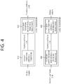
- FIG. 4 schematically illustrates a multiple transform technique according to an embodiment of the present disclosure.
- a transformer may correspond to the transformer in the encoding apparatus of foregoing FIG. 2
- an inverse transformer may correspond to the inverse transformer in the encoding apparatus of foregoing FIG. 2 , or to the inverse transformer in the decoding apparatus of FIG. 3 .
- the transformer may derive (primary) transform coefficients by performing a primary transform based on residual samples (residual sample array) in a residual block (S410).
- This primary transform may be referred to as a core transform.
- the primary transform may be based on multiple transform selection (MTS), and when a multiple transform is applied as the primary transform, it may be referred to as a multiple core transform.
- MTS multiple transform selection
- the multiple core transform may represent a method of transforming additionally using discrete cosine transform (DCT) type 2 and discrete sine transform (DST) type 7, DCT type 8, and/or DST type 1. That is, the multiple core transform may represent a transform method of transforming a residual signal (or residual block) of a space domain into transform coefficients (or primary transform coefficients) of a frequency domain based on a plurality of transform kernels selected from among the DCT type 2, the DST type 7, the DCT type 8 and the DST type 1.
- the primary transform coefficients may be called temporary transform coefficients from the viewpoint of the transformer.
- transform coefficients might be generated by applying transform from a space domain to a frequency domain for a residual signal (or residual block) based on the DCT type 2.
- transform coefficients (or primary transform coefficients) may be generated by applying transform from a space domain to a frequency domain for a residual signal (or residual block) based on the DCT type 2, the DST type 7, the DCT type 8, and/or DST type 1.
- the DCT type 2, the DST type 7, the DCT type 8, and the DST type 1 may be called a transform type, transform kernel or transform core.
- a vertical transform kernel and a horizontal transform kernel for a target block may be selected from among the transform kernels, a vertical transform for the target block may be performed based on the vertical transform kernel, and a horizontal transform for the target block may be performed based on the horizontal transform kernel.
- the horizontal transform may represent a transform for horizontal components of the target block
- the vertical transform may represent a transform for vertical components of the target block.
- the vertical transform kernel/horizontal transform kernel may be adaptively determined based on a prediction mode and/or a transform index of a target block (CU or sub-block) including a residual block.
- a mapping relationship for transform kernels may be set by setting specific basis functions to predetermined values and combining basis functions to be applied in the vertical transform or the horizontal transform.
- a trTypeHor or trTypeVer value of 0 may be set to DCT2
- a trTypeHor or trTypeVer value of 1 may be set to DST7
- a trTypeHor or trTypeVer value of 2 may be set to DCT8.
- MTS index information may be encoded and signaled to the decoding apparatus to indicate any one of a plurality of transform kernel sets.
- an MTS index of 0 may indicate that both trTypeHor and trTypeVer values are 0
- an MTS index of 1 may indicate that both trTypeHor and trTypeVer values are 1
- an MTS index of 2 may indicate that the trTypeHor value is 2 and the trTypeVer value.
- Is 1 an MTS index of 3 may indicate that the trTypeHor value is 1 and the trTypeVer value is 2
- an MTS index of 4 may indicate that both both trTypeHor and trTypeVer values are 2.
- transform kernel sets according to MTS index information are illustrated in the following table.
- the transformer may derive modified (secondary) transform coefficients by performing the secondary transform based on the (primary) transform coefficients (S420).
- the primary transform is a transform from a spatial domain to a frequency domain, and the secondary transform refers to transforming into a more compressive expression by using a correlation existing between (primary) transform coefficients.
- the secondary transform may include a non-separable transform.
- the secondary transform may be called a non-separable secondary transform (NSST), or a mode-dependent non-separable secondary transform (MDNSST).
- the non-separable secondary transform may represent a transform which generates modified transform coefficients (or secondary transform coefficients) for a residual signal by secondary-transforming, based on a non-separable transform matrix, (primary) transform coefficients derived through the primary transform.
- the vertical transform and the horizontal transform may not be applied separately (or horizontal and vertical transforms may not be applied independently) to the (primary) transform coefficients, but the transforms may be applied at once based on the non-separable transform matrix.
- the non-separable secondary transform may represent a transform method in which the vertical and horizontal components of the (primary) transform coefficients are not separated, and for example, two-dimensional signals (transform coefficients) are rearranged to a one-dimensional signal through a certain determined direction (e.g., row-first direction or column-first direction), and then modified transform coefficients (or secondary transform coefficients) are generated based on the non-separable transform matrix.
- a certain determined direction e.g., row-first direction or column-first direction
- modified transform coefficients or secondary transform coefficients
- M ⁇ N blocks are disposed in a line in an order of a first column, a second column, ..., and an Nth column.
- the non-separable secondary transform may be applied to a top-left region of a block configured with (primary) transform coefficients (hereinafter, may be referred to as a transform coefficient block). For example, if the width (W) and the height (H) of the transform coefficient block are all equal to or greater than 8, an 8x8 non-separable secondary transform may be applied to a top-left 8x8 region of the transform coefficient block.
- a 4x4 non-separable secondary transform may be applied to a top-left min(8,W) ⁇ min(8,H) region of the transform coefficient block.
- the embodiment is not limited to this, and for example, even if only the condition that the width (W) or height (H) of the transform coefficient block is equal to or greater than 4 is satisfied, the 4 ⁇ 4 non-separable secondary transform may be applied to the top-left min(8,W) ⁇ min(8,H) region of the transform coefficient block.
- the non-separable secondary transform may be performed as follows.
- the 4x4 input block X may be represented as follows.
- X X 00 X 01 X 02 X 03 X 10 X 11 X 12 X 13 X 20 X 21 X 22 X 23 X 30 X 31 X 32 X 33
- the vector X may be represented as below.
- X ⁇ X 00 X 01 X 02 X 03 X 10 X 11 X 12 X 13 X 20 X 21 X 22 X 23 X 30 X 31 X 32 X 33 T
- the vector X is a one-dimensional vector obtained by rearranging the two-dimensional block X of Equation 1 according to the row-first order.
- the secondary non-separable transform may be calculated as below.
- F ⁇ T ⁇ X ⁇
- F represents a transform coefficient vector
- T represents a 16x16 (non-separable) transform matrix
- a 16 ⁇ 1 transform coefficient vector F may be derived, and the F may be re-organized into a 4x4 block through a scan order (horizontal, vertical, diagonal and the like).
- the above-described calculation is an example, and hypercube-Givens transform (HyGT) or the like may be used for the calculation of the non-separable secondary transform in order to reduce the computational complexity of the non-separable secondary transform.
- HyGT hypercube-Givens transform
- a transform kernel (or transform core, transform type) may be selected to be mode dependent.
- the mode may include the intra prediction mode and/or the inter prediction mode.
- the non-separable secondary transform may be performed based on an 8x8 transform or a 4x4 transform determined based on the width (W) and the height (H) of the transform coefficient block.
- the 8x8 transform refers to a transform that is applicable to an 8x8 region included in the transform coefficient block when both W and H are equal to or greater than 8, and the 8x8 region may be a top-left 8x8 region in the transform coefficient block.
- the 4x4 transform refers to a transform that is applicable to a 4x4 region included in the transform coefficient block when both W and H are equal to or greater than 4, and the 4x4 region may be a top-left 4x4 region in the transform coefficient block.
- an 8x8 transform kernel matrix may be a 64x64/16x64 matrix
- a 4x4 transform kernel matrix may be a 16x16/8x16 matrix.
- two non-separable secondary transform kernels per transform set for a non-separable secondary transform may be configured for both the 8 ⁇ 8 transform and the 4 ⁇ 4 transform, and there may be four transform sets. That is, four transform sets may be configured for the 8 ⁇ 8 transform, and four transform sets may be configured for the 4 ⁇ 4 transform.
- each of the four transform sets for the 8 ⁇ 8 transform may include two 8 ⁇ 8 transform kernels
- each of the four transform sets for the 4 ⁇ 4 transform may include two 4 ⁇ 4 transform kernels.
- the sizes of the transforms, the numbers of sets, and the numbers of transform kernels in each set mentioned above are merely for illustration. Instead, a size other than 8x8 or 4x4 may be used, n sets may be configured, and k transform kernels may be included in each set.
- the transform set may be called an NSST set, and the transform kernel in the NSST set may be called an NSST kernel.
- the selection of a specific set from among the transform sets may be performed, for example, based on the intra prediction mode of the target block (CU or sub-block).
- the intra prediction mode may include two non-directional (or non-angular) intra prediction modes and 65 directional (or angular) intra prediction modes.
- the non-directional intra prediction modes may include a No. 0 planar intra prediction mode, and a No. 1 DC intra prediction mode
- the directional intra prediction modes may include 65 intra prediction modes between a No. 2 intra prediction mode and a No. 66 intra prediction mode.
- this is an example, and the present disclosure may be applied to a case where there are different number of intra prediction modes.
- a No. 67 intra prediction mode may be further used, and the No. 67 intra prediction mode may represent a linear model (LM) mode.
- LM linear model
- FIG. 5 illustrates directional intra modes of 65 prediction directions.
- the intra prediction mode having a horizontal directionality and the intra prediction mode having vertical directionality may be classified.
- H and V of FIG. 5 mean horizontal directionality and vertical directionality, respectively, and numerals -32 to 32 indicate displacements in 1/32 units on the sample grid position. This may represent an offset for the mode index value.
- the Nos. 2 to 33 intra prediction modes have the horizontal directionality, and the Nos. 34 to 66 intra prediction modes have the vertical directionality. Meanwhile, strictly speaking, the No. 34 intra prediction mode may be considered as being neither horizontal nor vertical, but it may be classified as belonging to the horizontal directionality in terms of determining the transform set of the secondary transform.
- the input data is transposed to be used for the vertical direction mode symmetrical on the basis of the No. 34 intra prediction mode, and the input data alignment method for the horizontal mode is used for the No. 34 intra prediction mode.
- Transposing input data means that rows and columns of two-dimensional block data MxN are switched into NxM data.
- the No. 18 intra prediction mode and the No. 50 intra prediction mode may represent a horizontal intra prediction mode and a vertical intra prediction mode, respectively, and the No. 2 intra prediction mode may be called a right upward diagonal intra prediction mode because it has a left reference pixel and predicts in a right upward direction.
- the No. 34 intra prediction mode may be called a right downward diagonal intra prediction mode
- the No. 66 intra prediction mode may be called a left downward diagonal intra prediction mode.
- one of the four transform sets may be mapped to one of four values, that is, 0 to 3, according to the intra prediction mode.
- one of k transform kernels in the specific set may be selected through the non-separable secondary transform index.
- the encoding apparatus may derive a non-separable secondary transform index indicating a specific transform kernel based on the rate-distortion (RD) check, and may signal the non-separable secondary transform index to the decoding apparatus.
- the decoding apparatus may select one from among k transform kernels in the specific set based on the non-separable secondary transform index.
- the NSST index value 0 may indicate a first non-separable secondary transform kernel
- the NSST index value 1 may indicate a second non-separable secondary transform kernel
- the NSST index value 2 may indicate a third non-separable secondary transform kernel.
- the NSST index value 0 may indicate that the first non-separable secondary transform is not applied to a target block
- the NSST index values 1 to 3 may indicate the three transform kernels.
- the transformer may perform the non-separable secondary transform based on the selected transform kernels, and may obtain modified (secondary) transform coefficients.
- the modified transform coefficients may be derived as transform coefficients quantized through the quantizer, and may be encoded and signaled to the decoding apparatus and transferred to the dequantizer/inverse transformer in the encoding apparatus.
- (primary) transform coefficients which are an output of the primary (separable) transform, may be derived as transform coefficients quantized through the quantizer as described above, and may be encoded and signaled to the decoding apparatus and transferred to the dequantizer/inverse transformer in the encoding apparatus.
- the inverse transformer may perform a series of procedures in the inverse order to that in which they have been performed in the above-described transformer.
- the inverse transformer may receive (dequantized) transformer coefficients, and derive (primary) transform coefficients by performing a secondary (inverse) transform (S450), and may obtain a residual block (residual samples) by performing a primary (inverse) transform on the (primary) transform coefficients (S460).
- the primary transform coefficients may be called modified transform coefficients from the viewpoint of the inverse transformer.
- the encoding apparatus and the decoding apparatus may generate the reconstructed block based on the residual block and the predicted block, and may generate the reconstructed picture based on the reconstructed block.
- the decoding apparatus may further include a secondary inverse transform application determinator (or an element to determine whether to apply a secondary inverse transform) and a secondary inverse transform determinator (or an element to determine a secondary inverse transform).
- the secondary inverse transform application determinator may determine whether to apply a secondary inverse transform.
- the secondary inverse transform may be an NSST or an RST, and the secondary inverse transform application determinator may determine whether to apply the secondary inverse transform based on a secondary transform flag obtained by parsing the bitstream.
- the secondary inverse transform application determinator may determine whether to apply the secondary inverse transform based on a transform coefficient of a residual block.
- the secondary inverse transform determinator may determine a secondary inverse transform.
- the secondary inverse transform determinator may determine the secondary inverse transform applied to the current block based on an NSST (or RST) transform set specified according to an intra prediction mode.
- a secondary transform determination method may be determined depending on a primary transform determination method.
- Various combinations of primary transforms and secondary transforms may be determined according to the intra prediction mode.
- the secondary inverse transform determinator may determine a region to which a secondary inverse transform is applied based on the size of the current block.
- the encoding apparatus and the decoding apparatus may generate the reconstructed block based on the residual block and the predicted block, and may generate the reconstructed picture based on the reconstructed block.
- a reduced secondary transform in which the size of a transform matrix (kernel) is reduced may be applied in the concept of NSST in order to reduce the amount of computation and memory required for the non-separable secondary transform.
- the transform kernel, the transform matrix, and the coefficient constituting the transform kernel matrix may be expressed in 8 bits. This may be a condition for implementation in the decoding apparatus and the encoding apparatus, and may reduce the amount of memory required to store the transform kernel with a performance degradation that can be reasonably accommodated compared to the existing 9 bits or 10 bits.
- the expressing of the kernel matrix in 8 bits may allow a small multiplier to be used, and may be more suitable for single instruction multiple data (SIMD) instructions used for optimal software implementation.
- the term "RST” may mean a transform which is performed on residual samples for a target block based on a transform matrix whose size is reduced according to a reduced factor.
- the amount of computation required for transform may be reduced due to a reduction in the size of the transform matrix. That is, the RST may be used to address the computational complexity issue occurring at the non-separable transform or the transform of a block of a great size.
- RST may be referred to as various terms, such as reduced transform, reduced secondary transform, reduction transform, simplified transform, simple transform, and the like, and the name which RST may be referred to as is not limited to the listed examples.
- the RST since the RST is mainly performed in a low frequency region including a non-zero coefficient in a transform block, it may be referred to as a Low-Frequency Non-Separable Transform (LFNST).
- LTNST Low-Frequency Non-Separable Transform
- the inverse transformer 235 of the encoding apparatus 200 and the inverse transformer 322 of the decoding apparatus 300 may include an inverse reduced secondary transformer which derives modified transform coefficients based on the inverse RST of the transform coefficients, and an inverse primary transformer which derives residual samples for the target block based on the inverse primary transform of the modified transform coefficients.
- the inverse primary transform refers to the inverse transform of the primary transform applied to the residual.
- deriving a transform coefficient based on a transform may refer to deriving a transform coefficient by applying the transform.
- FIG. 6 is a diagram illustrating an RST according to an embodiment of the present disclosure.
- a "target block” may refer to a current block to be coded, a residual block, or a transform block.
- an N-dimensional vector may be mapped to an R-dimensional vector located in another space, so that the reduced transform matrix may be determined, where R is less than N.
- N may mean the square of the length of a side of a block to which the transform is applied, or the total number of transform coefficients corresponding to a block to which the transform is applied, and the reduced factor may mean an R/N value.
- the reduced factor may be referred to as a reduced factor, reduction factor, simplified factor, simple factor or other various terms.
- R may be referred to as a reduced coefficient, but according to circumstances, the reduced factor may mean R. Further, according to circumstances, the reduced factor may mean the N/R value.
- the reduced factor or the reduced coefficient may be signaled through a bitstream, but the example is not limited to this.
- a predefined value for the reduced factor or the reduced coefficient may be stored in each of the encoding apparatus 200 and the decoding apparatus 300, and in this case, the reduced factor or the reduced coefficient may not be signaled separately.
- the size of the reduced transform matrix may be RxN less than N ⁇ N, the size of a conventional transform matrix, and may be defined as in Equation 4 below.
- T RxN t 11 t 12 t 13 ... t 1 N t 21 t 22 t 23 t 2 N ⁇ ⁇ ⁇ t R 1 t R 2 t R 3 ⁇ t RN
- the matrix T in the Reduced Transform block shown in FIG. 6A may mean the matrix TRxN of Equation 4. As shown in FIG. 6A , when the reduced transform matrix TRxN is multiplied to residual samples for the target block, transform coefficients for the target block may be derived.
- the RST according to FIG. 6A may be expressed as a matrix operation as shown in Equation 5 below. In this case, memory and multiplication calculation can be reduced to approximately 1/4 by the reduced factor.
- a matrix operation may be understood as an operation of multiplying a column vector by a matrix, disposed on the left of the column vector, to obtain a column vector.
- r1 to r64 may represent residual samples for the target block and may be specifically transform coefficients generated by applying a primary transform.
- the size of the regular transform matrix is 64x64 (N ⁇ N), but the size of the reduced transform matrix is reduced to 16x64 (RxN), so memory usage in a case of performing the RST can be reduced by an R/N ratio when compared with a case of performing the regular transform.
- the use of the reduced transform matrix can reduce the number of multiplication calculations by the R/N ratio (RxN).
- the transformer 232 of the encoding apparatus 200 may derive transform coefficients for the target block by performing the primary transform and the RST-based secondary transform on residual samples for the target block. These transform coefficients may be transferred to the inverse transformer of the decoding apparatus 300, and the inverse transformer 322 of the decoding apparatus 300 may derive the modified transform coefficients based on the inverse reduced secondary transform (RST) for the transform coefficients, and may derive residual samples for the target block based on the inverse primary transform for the modified transform coefficients.
- RST inverse reduced secondary transform
- the size of the inverse RST matrix TNxR according to an example is NxR less than the size N ⁇ N of the regular inverse transform matrix, and is in a transpose relationship with the reduced transform matrix TRxN shown in Equation 4.
- the matrix Tt in the Reduced Inv. Transform block shown in FIG. 6B may mean the inverse RST matrix TRxNT (the superscript T means transpose).
- T means transpose
- the modified transform coefficients for the target block or the residual samples for the target block may be derived.
- the inverse RST matrix TRxNT may be expressed as (TRxNT)NxR.
- the modified transform coefficients for the target block may be derived when the inverse RST matrix TRxNT is multiplied to the transform coefficients for the target block.
- the inverse RST may be applied as the inverse primary transform, and in this case, the residual samples for the target block may be derived when the inverse RST matrix TRxNT is multiplied to the transform coefficients for the target block.
- the RST according to FIG. 6B may be expressed as a matrix operation as shown in Equation 7 below.
- Equation 7 t 1,1 t 2,1 t 16,1 t 1,2 t 2,2 ... t 16,2 t 1,3 t 2,3 t 16,3 ⁇ ⁇ ⁇ ⁇ ⁇ t 1,64 t 2,64 ⁇ t 16,64 ⁇ c 1 c 2 ⁇ c 16
- Equation 7 c1 to c16 may represent the transform coefficients for the target block.
- r1 to rN representing the modified transform coefficients for the target block or the residual samples for the target block may be derived.
- the size of the regular inverse transform matrix is 64x64 (NxN), but the size of the reduced inverse transform matrix is reduced to 64 ⁇ 16 (RxN), so memory usage in a case of performing the inverse RST can be reduced by an R/N ratio when compared with a case of performing the regular inverse transform.
- the use of the reduced inverse transform matrix can reduce the number of multiplication calculations by the R/N ratio (NxR).
- a transform set configuration shown in Table 2 may also be applied to an 8x8 RST. That is, the 8x8 RST may be applied according to a transform set in Table 2. Since one transform set includes two or three transforms (kernels) according to an intra prediction mode, it may be configured to select one of up to four transforms including that in a case where no secondary transform is applied. In a transform where no secondary transform is applied, it may be considered to apply an identity matrix.
- index 0 may be allocated to a case where an identity matrix is applied, that is, a case where no secondary transform is applied
- an NSST index as a syntax element may be signaled for each transform coefficient block, thereby designating a transform to be applied. That is, through the NSST index, it is possible to designate an 8x8 NSST for a top-left 8x8 block and to designate an 8x8 RST in an RST configuration.
- the 8x8 NSST and the 8x8 RST refer to transforms applicable to an 8x8 region included in the transform coefficient block when both W and H of the target block to be transformed are equal to or greater than 8, and the 8x8 region may be a top-left 8x8 region in the transform coefficient block.
- a 4x4 NSST and a 4x4 RST refer to transforms applicable to a 4x4 region included in the transform coefficient block when both W and H of the target block to are equal to or greater than 4, and the 4x4 region may be a top-left 4x4 region in the transform coefficient block.
- a maximum 16 ⁇ 48 transform kernel matrix may be applied thereto, rather than applying a 16 ⁇ 64 transform kernel matrix to 64 pieces of data forming an 8 ⁇ 8 region.
- maximum means that m has a maximum value of 16 in an m ⁇ 48 transform kernel matrix for generating m coefficients. That is, when an RST is performed by applying an m ⁇ 48 transform kernel matrix (m ⁇ 16) to an 8 ⁇ 8 region, 48 pieces of data are input and m coefficients are generated. When m is 16, 48 pieces of data are input and 16 coefficients are generated.
- a 16 ⁇ 48 matrix and a 48 ⁇ 1 vector are sequentially multiplied, thereby generating a 16 ⁇ 1 vector.
- the 48 pieces of data forming the 8 ⁇ 8 region may be properly arranged, thereby forming the 48 ⁇ 1 vector.
- 16 modified transform coefficients are generated, and the 16 modified transform coefficients may be arranged in a top-left 4 ⁇ 4 region according to a scanning order, and a top-right 4 ⁇ 4 region and a bottom-left 4 ⁇ 4 region may be filled with zeros.
- the transposed matrix of the foregoing transform kernel matrix may be used. That is, when an inverse RST or LFNST is performed in an inverse transform process performed by the decoding apparatus, input coefficient data to which the inverse RST is applied is configured in a one-dimensional vector according to a predetermined arrangement order, and a modified coefficient vector obtained by multiplying the one-dimensional vector and a corresponding inverse RST matrix on the left of the one-dimensional vector may be arranged in a two-dimensional block according to a predetermined arrangement order.
- a matrix operation of 48 transform coefficients in top-left, top-right, and bottom-left regions of the 8 ⁇ 8 region excluding the bottom-right region among transform coefficients in the 8 ⁇ 8 region and a 16 ⁇ 48 transform kernel matrix For the matrix operation, the 48 transform coefficients are input in a one-dimensional array. When the matrix operation is performed, 16 modified transform coefficients are derived, and the modified transform coefficients may be arranged in the top-left region of the 8 ⁇ 8 region.
- an n ⁇ 1 vector may be interpreted to have the same meaning as an n ⁇ 1 matrix and may thus be expressed as an n ⁇ 1 column vector.
- ⁇ denotes matrix multiplication.
- 48 modified transform coefficients may be derived, and the 48 modified transform coefficients may be arranged in top-left, top-right, and bottom-left regions of the 8x8 region excluding a bottom-right region.
- the inverse transformer 235 of the encoding apparatus 200 and the inverse transformer 322 of the decoding apparatus 300 may include an inverse reduced secondary transformer to derive modified transform coefficients based on an inverse RST on transform coefficients and an inverse primary transformer to derive residual samples for a target block based on an inverse primary transform on the modified transform coefficients.
- the inverse primary transform refers to the inverse transform of a primary transform applied to a residual.
- deriving a transform coefficient based on a transform may refer to deriving the transform coefficient by applying the transform.
- the encoding apparatus may perform various encoding methods, such as exponential Golomb coding, context-adaptive variable length coding (CAVLC), and context-adaptive binary arithmetic coding (CABAC).
- the decoding apparatus may decode information in a bitstream based on a coding method, such as exponential Golomb coding, CAVLC, or CABAC, and may output the value of a syntax element necessary for image reconstruction and quantized values of a transform coefficient regarding a residual.
- the foregoing coding methods may be performed as described below.
- FIG. 7 illustrates context-adaptive binary arithmetic coding (CABAC) for encoding a syntax element.
- CABAC context-adaptive binary arithmetic coding
- the encoding apparatus may convert an input signal to a binary value through binarization when the input signal is a syntax element rather than a binary value.
- the input signal is an already binary value (that is, the value of the input signal is a binary value)
- the input signal is bypassed without binarization.
- each binary 0 or 1 forming the binary value may be referred to as a bin.
- a bin For example, when a binary string resulting from the binarization is 110, each of 1, 1, and 0 is called one bin.
- the bin(s) for one syntax element may indicate the value of the syntax element.
- the binarization may be based on various binarization methods, such as a truncated Rice binarization process and a fixed-length binarization process, and a binarization method for a target syntax element may be predefined.
- This binarization procedure may be performed by a binarizer in the entropy encoder.
- the binarized bins of the syntax element may be input to a regular coding engine or a bypass coding engine.
- the regular coding engine of the encoding apparatus may assign a context model that reflects a probability value for the bins and may encode the bins based on the assigned context model.
- the regular coding engine of the encoding apparatus may encode on each bin and may then update the context model for the bin. These encoded bins may be referred to as context-coded bins.
- the bins may be coded as follows.
- the bypass coding engine of the encoding apparatus omits a procedure of estimating a probability for the input bins and a procedure of updating a probability model applied to the bins after encoding.
- the encoding apparatus may encode the input bits by applying a uniform probability distribution instead of assigning a context model, thus increasing encoding speed.
- These coded bins may be referred to as bypass bins.
- Entropy decoding may be performed by the same process as entropy encoding described above in reverse order.
- the decoding apparatus may decode encoded image/video information.
- the image/video information may include partitioning-related information, prediction-related information (e.g., inter/intra prediction classification information, intra prediction mode information, and inter prediction mode information), residual information, in-loop filtering-related information, and the like, or may include various syntax elements relating thereto.
- prediction-related information e.g., inter/intra prediction classification information, intra prediction mode information, and inter prediction mode information
- residual information e.g., in-loop filtering-related information, and the like
- the foregoing entropy coding may be performed in syntax element units.
- the decoding apparatus may perform binarization on a target syntax element.
- the binarization may be based on various binarization methods, such as a truncated Rice binarization process and a fixed-length binarization process, and a binarization method for the target syntax element may be predefined.
- the decoding apparatus may derive available bin strings (bin string candidates) for available values of the target syntax element through this binarization procedure.
- the binarization procedure may be performed by a binarizer in the entropy decoder.
- the decoding apparatus sequentially decodes and parses individual bins for the target syntax element from an input bit(s) in a bitstream and compares a derived bin string with the available bin strings for the syntax element. When the derived bin string is the same as one of the available bin strings, a value corresponding to the bin string is derived as the value of the syntax element. Otherwise, the decoding apparatus further parses a next bit in the bitstream and performs the above procedure again. Through this process, specific information (specific syntax element) in the bitstream may be signaled using a variable-length bit without using a start bit or an end bit for the specific information. Accordingly, a smaller number of bits may be allocated to a lower value, and overall coding efficiency may be improved.
- the decoding apparatus may perform context-based or bypass-based decoding on each bin in the bin string from the bitstream based on an entropy coding technique, such as CABAC or CAVLC.
- an entropy coding technique such as CABAC or CAVLC.
- the decoding apparatus may receive a bin corresponding to the syntax element through the bitstream, may determine the context model using the syntax element and decoding information on a block to be decoded or a neighboring block or information on a symbol/bin decoded in a previous step, and may derive the value of the syntax element by predicting the probability of the received bin occurring and performing arithmetic decoding of the bin according to the determined context model. Subsequently, a context model for a bin to be subsequently decoded may be updated to the determined context model.
- a context model may be assigned and updated for each bin to be context-coded (regularly coded) and may be indicated based on ctxIdx or ctxInc.
- ctxIdx may be derived based on ctxInc.
- a context index (ctxIdx) indicating a context model for each regularly coded bin may be derived as the sum of a context index increment (ctxInc) and a context index offset (ctxIdxOffset).
- ctxIdxOffset may be expressed as the lowest value of ctxIdx.
- ctxIdxOffset is a value generally used for distinguishing from context models for other syntax elements, and a context model for one syntax element may be classified/derived based on ctxInc.
- Entropy decoding may be performed by the same process as encoding in reverse order.
- the decoding apparatus may receive the bin corresponding to the syntax element through the bitstream and may decode the input bin by applying a uniform probability distribution. In this case, the decoding apparatus may omit the procedure of deriving the context model for the syntax element and the procedure of updating the context model applied to the bin after decoding.
- residual samples may be derived as quantized transform coefficients through transform and quantization processes.
- the quantized transform coefficients may also be referred to as transform coefficients.
- the transform coefficients within a block may be signaled in the form of residual information.
- the residual information may include a residual coding syntax. That is, the encoding apparatus may construct the residual coding syntax with the residual information, may encode the residual coding syntax, and may output residual coding syntax in the form of a bitstream, and the decoding apparatus may decode the residual coding syntax from the bitstream and may derive residual (quantized) transform coefficients.
- the residual coding syntax may include syntax elements indicating whether a transform is applied to the block, the position of the last significant transform coefficient in the block, whether there is a significant transform coefficient in a subblock, the size/code of a significant transform coefficient, and the like.
- a method for binarization and context modeling of information indicating a secondary transform kernel (e.g., transform index st_idx) may be proposed.
- Table 3 shows part of the syntax of a TU according to an example, and Table 4 shows part of the syntax of a coding unit.
- tu_mts_idx[x0][y0] denotes an MTS index applied to a transform block
- trTypeHor and trTypeVer may be determined according to the MTS index as shown in Table 1.
- the transform index (st_idx) indicates a secondary transform kernel matrix indicating any one of two candidate transform kernels included in a selected transform set.
- a transform index of 0 indicates that a secondary transform is not applied.
- the transform index may be mapped to an intra prediction mode as shown in Table 2 and may be derived based on the selected transform set.
- each bin of the binary string is referred to as a bin
- each bin of the binary string is may be coded by context-adaptive binary arithmetic coding (CABAC) of coding with designated context or by bypass coding.
- CABAC context-adaptive binary arithmetic coding
- Bypass coding is a coding scheme of assigning a probability of 0.5 without context
- CABAC which may be referred to as regular coding, is a coding scheme of obtaining a probability value to be applied to coding from context information, that is, probability information.
- M pieces of context information may be used to code N bins, and each piece of context information may be applied to coding of one bin at a specific position or may be applied to coding of a plurality of bins at a plurality of positions.
- M may be the same as or less than N.
- Each context may be updated through a method applied in a codec (e.g., HEVC or VVC) using CABAC, and regular coding described above may also follow the method applied in the existing codec.
- a codec e.g., HEVC or VVC
- CABAC CABAC
- context A may be applied when coding a first bin
- context B may be applied when coding a second bin.
- Table 5 and Table 6 show a process of deriving the context increment (ctxInc) of the transformation index.
- Table 5 shows that when binarization of the transform index is performed by truncated Rice binarization, the maximum value of the index is 2. Further, since cRiceParam is 0, the binarization is performed by truncated unary binarization.
- Table 6 shows that the ctxInc value of a context-coded bin is derived.
- the first bin of the transform index may be derived based on any one of four ctxInc values (0, 1, 4, 5), and the second bin may also be derived based on any one of four ctxInc values (2, 3, 6, 7).
- the ctxInc value may be derived based on a variable mtsCtx.
- the tree type may be classified as a single tree (SINGLE_TREE) type or a dual tree (DUAL_TREE) type according to whether a chroma block corresponding to a luma block has a separate partitioning structure.
- the tree type When the chroma block has the same partitioning structure as that of the luma block, the tree type may be a single tree, and when the chroma block has a different partitioning structure from that of the luma block, the tree type may be a dual tree.
- the ctxInc value of the context-coded bin of the transform index may be derived as shown in the following table.
- Table 7 also shows a process of deriving ctxInc of the transform index.
- the first bin may be derived based on one of two ctxInc values (0, 1), and the second bin may be derived based on bypass coding rather than a context model.
- the second bin may be derived based on bypass coding rather than a context model.
- a ctxInc value regarding which of the two contexts to select may be determined as in Section 9.5.4.2.8.
- ctxInc may be directly derived according to the MTS index and the tree type without being based on the value of another variable, for example, an intermediate variable including mtsCtx in Table 6.
- Table 7 may be expressed in a different manner as shown in Table 8.
- Table 8 omits Section 9.5.4.2.8 included in Table 7, a description of a process of deriving ctxInc of the transform index is the same as that of Table 7.
- the ctxInc value of the context-coded bin of the transform index may be derived as shown in the following table.
- Table 9 shows that the ctxInc value of a context-coded bin is derived.
- the first bin of the transform index may be derived based on any one of four ctxInc values (0, 1, 4, 5), and the second bin may also be derived based on any one of four ctxInc values (2, 3, 6, 7).
- the ctxInc value may be derived based on a variable mtsCtx.
- the ctxInc value of the context-coded bin of the transform index may be derived as shown in the following table.
- Table 10 also shows a process of deriving ctxInc of the transform index.
- the first bin may be derived based on one of two ctxInc values (0, 1), and the second bin may be derived based on bypass coding rather than a context model.
- the second bin may be derived based on bypass coding rather than a context model.
- a ctxInc value regarding which of the two contexts to select may be determined as in Section 9.5.4.2.8.
- ctxInc may be directly derived according to the MTS index and the tree type without being based on the value of another variable, for example, an intermediate variable including mtsCtx in Table 9.
- Table 10 may be expressed in a different manner as shown in Table 11.
- Table 11 omits Section 9.5.4.2.8 included in Table 10, a description of a process of deriving ctxInc of the transform index is the same as that of Table 10.
- the decoding apparatus may decode the transform index.
- the MTS index when the MTS index is not received, the MTS index may be inferred as 0, and the processes of Table 9 to Table 11 may be applied. That is, when the MTS index has not been received or decoded, the MTS index may be inferred as 0, and the context information on the first bin of the transform index may be derived as 1, when the tree type of the target block is not a single tree type, and may be derived as 0, when the tree type of the target block is the single tree type.
- the encoding apparatus may code the transform index.
- the MTS index when the MTS index is not coded, the MTS index may be inferred as 0, and the processes of Table 9 to Table 11 may be applied. That is, when the MTS index has not been generated or encoded, the MTS index may be inferred as 0, and the context information on the first bin of the transform index may be derived as 1, when the tree type of the target block is not the single tree type, and may be derived as 0, when the tree type of the target block is the single tree type.
- both the first bin and the second bin of the transform index may be coded based on a context model. That is, first context model information may be used for the first bin, and second context model information may be used for the second bin.
- the context information may be ctxInc or may be derived based on ctxInc, and the first context model information and the second context model information may have different values.
- the first context model information may be 0 or 1 according to the tree type of the target block to be transformed, and the second context model information may be set to a specific value regardless of the tree type.
- the first context model information may be derived as 1 when the MTS index is 0 and the tree type is not the single tree type, and may be derived as 0 otherwise, that is, when the MTS index is not 0 or the tree type is the single tree type.
- the first context model information may be derived as 0 or 1 according to the tree type regardless of the MTS index. That is, the first context model information may be derived as 1 when the tree type of the target block is not the single tree type, and may be derived as 0 when the tree type of the target block is the single tree type.
- FIG. 8 is a flowchart illustrating an operation of a video decoding apparatus according to an embodiment of the present disclosure.
- Each operation illustrated in FIG. 8 may be performed by the decoding apparatus 300 illustrated in FIG. 3 .
- S810 may be performed by the entropy decoder 310 illustrated in FIG. 3
- S820 may be performed by the dequantizer 321 illustrated in FIG. 3
- S830 and S840 may be performed by the inverse transformer 322 illustrated in FIG. 3
- S850 may be performed by the adder 340 illustrated in FIG. 3 .
- Operations according to S810 to S850 are based on some of the foregoing details explained with reference to FIG. 4 to FIG. 7 . Therefore, a description of specific details overlapping with those explained above with reference to FIG. 4 to FIG. 7 will be omitted or will be made briefly.
- the decoding apparatus 300 may derive quantized transform coefficients for a target block from a bitstream (S810). Specifically, the decoding apparatus 300 may decode information on the quantized transform coefficients for the target block from the bitstream and may derive the quantized transform coefficients for the target block based on the information on the quantized transform coefficients for the target block.
- the information on the quantized transform coefficients for the target block may be included in a sequence parameter set (SPS) or a slice header and may include at least one of information on whether a reduced transform (RST) is applied, information on a reduced factor, information on a minimum transform size to which the RST is applied, information on a maximum transform size to which the RST is applied, information on a reduced inverse transform size, and information on a transform index indicating any one of transform kernel matrices included in a transform set.
- SPS sequence parameter set
- RST reduced transform
- the decoding apparatus 300 may derive transform coefficients by dequantizing the quantized transform coefficients for the target block (S820).
- the decoding apparatus 300 may derive modified transform coefficients based on an inverse non-separable transform or an inverse reduced secondary transform (RST) of the transform coefficients (S830).
- RST inverse reduced secondary transform
- the inverse non-separable transform or the inverse RST may be performed based on an inverse RST transform matrix, and the inverse RST transform matrix may be a nonsquare matrix in which the number of columns is less than the number of rows.
- S830 may include decoding a transform index, determining whether a condition for applying an inverse RST is satisfied based on the transform index, selecting a transform kernel matrix, and applying the inverse RST to the transform coefficients based on the selected transform kernel matrix and/or the reduced factor when the condition for applying the inverse RST is satisfied.
- the size of an inverse RST matrix may be determined based on the reduced factor.
- the decoding apparatus 300 may derive residual samples for the target block based on an inverse transform of the modified transform coefficients (S840).
- the decoding apparatus 300 may perform an inverse primary transform on the modified transform coefficients for the target block, in which case a reduced inverse transform may be applied or a conventional separable transform may be used as the inverse primary transform.
- the decoding apparatus 300 may generate reconstructed samples based on the residual samples for the target block and prediction samples for the target block (S850).
- the residual samples for the target block are derived based on the inverse RST of the transform coefficients for the target block.
- the size of a regular inverse transform matrix is N ⁇ N but the size of the inverse RST matrix is reduced to N ⁇ R, it is possible to reduce memory usage in a case of performing the inverse RST by an R/N ratio compared to that in a case of performing a regular transform.
- using the inverse RST matrix can reduce the number of multiplications (N ⁇ R) by the R/N ratio, compared to the number of multiplications N ⁇ N in a case of using the regular inverse transform matrix.
- the total number of transform coefficients for the target block may be reduced from N to R, compared to that in a case where N transform coefficients needs to be decoded when a regular inverse transform is applied, thus increasing decoding efficiency. That is, according to S830, the (inverse) transform efficiency and decoding efficiency of the decoding apparatus 300 may be increased through the inverse RST.
- FIG. 9 is a control flowchart illustrating an inverse non-separable transform method based on a transform index according to an embodiment of the present disclosure.
- the decoding apparatus 300 receives information on a transform index and an intra prediction mode from a bitstream (S900).
- the decoding apparatus 300 may further receive MTS index information indicating a transform kernel of an inverse primary transform.
- the information on the transform index is received as syntax information, and the syntax information is received as a bin string including a 0 and a 1.
- the entropy decoder 310 may derive binarization information on a syntax element of the transform index.
- This operation is generating a candidate set for a binary value that the syntax element of the received transform index can have.
- the syntax element of the transform index may be binarized by truncated unary coding.
- the syntax element of the transform index may indicate whether an inverse RST or an inverse non-separable transform is applied and one of transform kernel matrices included in a transform set.
- the syntax element of the transform index may have three values.
- the value of the syntax element of the transform index may include 0 indicating that the inverse RST is not applied to a target block, 1 indicating a first transform kernel matrix of the transform kernel matrices, and 2 indicating a second transform kernel matrix of the transform kernel matrices.
- the three values of the syntax element of the transform index may be coded into 0, 10, and 11, respectively, according to truncated unary coding. That is, the value of the syntax element of 0 may be binarized into '0', the value of the syntax element of 1 may be binarized into '10', and the value of the syntax element of 2 may be binarized into '11'.
- the entropy decoder 310 may derive context information, that is, a context model, on the bin string of the transform index according to the value of an MTS index and the tree type of a target block (S910) and may decode bins of the bin string of the syntax element based on the context information (S920).
- context information that is, a context model, on the bin string of the transform index according to the value of an MTS index and the tree type of a target block (S910) and may decode bins of the bin string of the syntax element based on the context information (S920).
- different pieces of context information may be applied to two bins of the transform index, respectively. That is, all of the two bins of the transform index may be decoded by a context method rather than by a bypass method, wherein a first bin of the bins of the syntax element of the transform index may be decoded based on first context information, and a second bin of the bins of the syntax element of the transform index may be decoded based on second context information.
- the first bin of the two bins of the transform index may be decoded by the context method, and the second bin may be decoded by the bypass method.
- the context information may be derived as a different value depending on the value of the MTS index and the tree type of the target block.
- the tree type of the target block may be classified as a single tree (SINGLE_TREE) or a dual tree (DUAL_TREE) according to whether a chroma block corresponding to a luma block has a separate partitioning structure.
- the tree type may be the single tree
- the chroma block has a different partitioning structure from that of the luma block
- the tree type may be the dual tree.
- first context information may be used when coding the transform index
- second context information may be used when coding the transform index.
- the first context information may be derived as a different value depending on the value of the MTS index.
- the first context information may be derived as 1 when the MTS index is 0 and the tree type is not a single tree type, and may be derived as 0 otherwise, that is, when the MTS index is not 0 or the tree type is the single tree type.
- the MTS index when the MTS index is not received or decoded, the MTS index may be inferred as 0. In this case, since a condition that the MTS index is 0 is satisfied, the transform index may be derived as 1 when the tree type is not the single tree type, and may be derived as 0 when the tree type is the single tree type.
- the entropy decoder 310 receives the bin string binarized by truncated unary coding and decodes the syntax element of the transform index of the binary value based on the context information.
- the value of the syntax element of the transform index applied to the target block among binary values that the syntax element of the transform index can have may be derived by this context information-based decoding (S930).
- the inverse transformer 322 of the decoding apparatus 300 determines a transform set based on a mapping relationship according to the intra prediction mode applied to the target block (S940) and may perform an inverse RST, that is, an inverse non-separable transform, based on the transform set and the value of the syntax element of the transform index (S950).
- a plurality of transform sets may be determined according to an intra prediction mode of a transform block to be transformed, and an RST may be performed based on any one of transform kernel matrices included in a transform set indicated by a transform index.
- FIG. 10 is a flowchart illustrating an operation of a video encoding apparatus according to an embodiment of the present disclosure.
- Each operation illustrated in FIG. 10 may be performed by the encoding apparatus 200 illustrated in FIG. 2 .
- S1010 may be performed by the predictor 220 illustrated in FIG. 2
- S1020 may be performed by the subtractor 231 illustrated in FIG. 2
- S1030 and S1040 may be performed by the transformer 232 illustrated in FIG. 2
- S1050 may be performed by the quantizer 233 and the entropy encoder 240 illustrated in FIG. 2 .
- Operations according to S1010 to S1050 are based on some of contents described in FIG. 4 to FIG. 7 . Therefore, a description of specific details overlapping with those explained above with reference to FIG. 4 to FIG. 7 will be omitted or will be made briefly.
- the encoding apparatus 200 may derive prediction samples based on an intra prediction mode applied to a target block (S1010).
- the encoding apparatus 200 may derive residual samples for the target block (S1020).
- the encoding apparatus 200 may derive transform coefficients for the target block based on primary transform of the residual sample (S 1030).
- the primary transform may be performed through a plurality of transform kernels, and the transform kernels may be selected based on the intra prediction mode.
- the decoding apparatus 300 may perform a secondary transform or a non-separable transform, specifically an NSST, on the transform coefficients for the target block, in which case the NSST may be performed based on a reduced transform (RST) or without being based on the RST.
- RST reduced transform
- an operation according to S1040 may be performed.
- the encoding apparatus 200 may derive modified transform coefficients for the target block based on the RST of the transform coefficients (S 1040).
- the RST may be performed based on a reduced transform matrix or a transform kernel matrix, and the reduced transform matrix may be a nonsquare matrix in which the number of rows is less than the number of columns.
- S1040 may include determining whether a condition for applying the RST is satisfied, generating and encoding the transform index based on the determination, selecting a transform kernel, and applying the RST to the residual samples based on the selected transform kernel matrix and/or a reduced factor when the condition for applying the RST is satisfied.
- the size of the reduced transform kernel matrix may be determined based on the reduced factor.
- the encoding apparatus 200 may derive quantized transform coefficients by performing quantization based on the modified transform coefficients for the target block and may encode information on the quantized transform coefficients (S 1050).
- the encoding apparatus 200 may generate the information on the quantized transform coefficients and may encode the generated information on the quantized transform coefficients.
- the information on the quantized transform coefficients may include at least one of information on whether the RST is applied, information on the reduced factor, information on a minimum transform size to which the RST is applied, and information on a maximum transform size to which the RST is applied.
- the transform coefficients for the target block are derived based on the RST of the residual samples.
- the size of a regular transform kernel matrix is N ⁇ N but the size of the reduced transform matrix is reduced to R ⁇ N, it is possible to reduce memory usage in a case of performing the RST by an R/N ratio compared to that in a case of performing a regular transform.
- using the reduced transform kernel matrix can reduce the number of multiplications (R ⁇ N) by the R/N ratio, compared to the number of multiplications N ⁇ N in a case of using the regular transform kernel matrix.
- the total number of transform coefficients for the target block may be reduced from N to R, compared to that in a case where N transform coefficients are derived when a regular transform is applied, thus reducing the amount of data transmitted by the encoding apparatus 200 to the decoding apparatus 300. That is, according to S1040, the transform efficiency and coding efficiency of the encoding apparatus 320 may be increased through the RST.
- FIG. 11 is a control flowchart illustrating a non-separable transform method including encoding of a transform index according to an embodiment of the present disclosure.
- the encoding apparatus 200 may determine a transform set based on a mapping relationship according to an intra prediction mode applied to a target block (S1100).
- the encoding apparatus 200 may perform a primary transform based on an MTS before a non-separable transform based on the transform set, an MTS index indicating which MTS is used may be generated.
- the transformer 232 may derive a transform coefficient by performing an RST, that is, a non-separable transform, based on any one of transform kernel matrices included in the transform set (S1110).
- the transform coefficient may be a modified transform coefficient resulting from a primary transform and then a secondary transform, and two transform kernel matrices may be included in each transform set.
- information on the RST may be encoded by the entropy encoder 240.
- the entropy encoder 240 may derive the value of a syntax element of a transform index indicating any one of the transform kernel matrices included in the transform set (S1120).
- the syntax element of the transform index may indicate whether an (inverse) RST is applied and any one of the transform kernel matrices included in the transform set.
- the syntax element of the transform index may have three values.
- the value of the syntax element of the transform index may be derived as 0 indicating that the (inverse) RST is not applied to a target block, as 1 indicating a first transform kernel matrix of the transform kernel matrices, or as 2 indicating a second transform kernel matrix of the transform kernel matrices.
- the entropy encoder 240 may binarize the derived value of the syntax element of the transform index (S1130).
- the entropy encoder 240 may binarize the three values of the syntax element of the transform index into 0, 10, and 11 according to truncated unary coding. That is, the value of the syntax element of 0 may be binarized into '0', the value of the syntax element of 1 may be binarized into '10', and the value of the syntax element of 2 may be binarized into '11', and the entropy encoder 240 may binarize the derived syntax element of the transform index into one of '0', '10, and '11'.
- the entropy encoder 240 may derive context information, that is, a context model, on a bin string of the transform index (S 1140) according to the value of the MTS index and the tree type of the target block and may encode bins of the bin string of the syntax element based on the context information (S1150).
- context information that is, a context model, on a bin string of the transform index (S 1140) according to the value of the MTS index and the tree type of the target block and may encode bins of the bin string of the syntax element based on the context information (S1150).
- different pieces of context information may be applied to two bins of the transform index, respectively. That is, all of the two bins of the transform index may be encoded by a context method rather than by a bypass method, wherein a first bin of the bins of the syntax element of the transform index may be decoded based on first context information, and a second bin of the bins of the syntax element of the transform index may be decoded based on second context information.
- the first bin of the two bins of the transform index may be encoded by the context method, and the second bin may be encoded by the bypass method.
- the context information may be derived as a different value depending on the value of the MTS index and the tree type of the target block.
- the tree type of the target block may be classified as a single tree (SINGLE_TREE) or a dual tree (DUAL_TREE) according to whether a chroma block corresponding to a luma block has a separate partitioning structure.
- the tree type may be the single tree
- the chroma block has a different partitioning structure from that of the luma block
- the tree type may be the dual tree.
- first context information may be used when coding the transform index
- second context information may be used when coding the transform index.
- the first context information may be derived as a different value depending on the value of the MTS index.
- the first context information may be derived as 1 when the MTS index is 0 and the tree type is not a single tree type, and may be derived as 0 otherwise, that is, when the MTS index is not 0 or the tree type is the single tree type.
- the MTS index when the MTS index is not generated or encoded, the MTS index may be inferred as 0. In this case, since a condition that the MTS index is 0 is satisfied, the transform index may be derived as 1 when the tree type is not the single tree type, and may be derived as 0 when the tree type is the single tree type.
- the entropy encoder 240 derives the bin string binarized by truncated unary coding and encodes the syntax element of the transform index of the binary value based on the context information.
- At least one of quantization/dequantization and/or transform/inverse transform may be omitted.
- a quantized transform coefficient may be referred to as a transform coefficient.
- transform/inverse transform is omitted, the transform coefficient may be referred to as a coefficient or a residual coefficient, or may still be referred to as a transform coefficient for consistency of expression.
- a quantized transform coefficient and a transform coefficient may be referred to as a transform coefficient and a scaled transform coefficient, respectively.
- residual information may include information on a transform coefficient(s), and the information on the transform coefficient(s) may be signaled through a residual coding syntax.
- Transform coefficients may be derived based on the residual information (or information on the transform coefficient(s)), and scaled transform coefficients may be derived through inverse transform (scaling) of the transform coefficients. Residual samples may be derived based on the inverse transform (transform) of the scaled transform coefficients.
- an encoding apparatus and/or decoding apparatus may be included in a device for image processing, such as, a TV, a computer, a smartphone, a set-top box, a display device or the like.
- the above-described methods may be embodied as modules (processes, functions or the like) to perform the above-described functions.
- the modules may be stored in a memory and may be executed by a processor.
- the memory may be inside or outside the processor and may be connected to the processor in various well-known manners.
- the processor may include an application-specific integrated circuit (ASIC), other chipset, logic circuit, and/or a data processing device.
- the memory may include a read-only memory (ROM), a random access memory (RAM), a flash memory, a memory card, a storage medium, and/or other storage device.
- embodiments described in the present disclosure may be embodied and performed on a processor, a microprocessor, a controller or a chip.
- function units shown in each drawing may be embodied and performed on a computer, a processor, a microprocessor, a controller or a chip.
- the decoding apparatus and the encoding apparatus to which the present disclosure is applied may be included in a multimedia broadcasting transceiver, a mobile communication terminal, a home cinema video device, a digital cinema video device, a surveillance camera, a video chat device, a real time communication device such as video communication, a mobile streaming device, a storage medium, a camcorder, a video on demand (VoD) service providing device, an over the top (OTT) video device, an Internet streaming service providing device, a three-dimensional (3D) video device, a video telephony video device, and a medical video device, and may be used to process a video signal or a data signal.
- the over the top (OTT) video device may include a game console, a Blu-ray player, an Internet access TV, a Home theater system, a smartphone, a Tablet PC, a digital video recorder (DVR) and the like.
- the processing method to which the present disclosure is applied may be produced in the form of a program executed by a computer, and be stored in a computer-readable recording medium.
- Multimedia data having a data structure according to the present disclosure may also be stored in a computer-readable recording medium.
- the computer-readable recording medium includes all kinds of storage devices and distributed storage devices in which computer-readable data are stored.
- the computer-readable recording medium may include, for example, a Blu-ray Disc (BD), a universal serial bus (USB), a ROM, a PROM, an EPROM, an EEPROM, a RAM, a CD-ROM, a magnetic tape, a floppy disk, and an optical data storage device.
- the computer-readable recording medium includes media embodied in the form of a carrier wave (for example, transmission over the Internet).
- a bitstream generated by the encoding method may be stored in a computer-readable recording medium or transmitted through a wired or wireless communication network.
- the embodiments of the present disclosure may be embodied as a computer program product by program codes, and the program codes may be executed on a computer by the embodiments of the present disclosure.
- the program codes may be stored on a computer-readable carrier.
- FIG. 12 illustrates the structure of a content streaming system to which the present disclosure is applied.
- the contents streaming system to which the present disclosure is applied may largely include an encoding server, a streaming server, a web server, a media storage, a user equipment, and a multimedia input device.
- the encoding server functions to compress to digital data the contents input from the multimedia input devices, such as the smart phone, the camera, the camcoder and the like, to generate a bitstream, and to transmit it to the streaming server.
- the encoding server may be omitted.
- the bitstream may be generated by an encoding method or a bitstream generation method to which the present disclosure is applied.
- the streaming server may store the bitstream temporarily during a process to transmit or receive the bitstream.
- the streaming server transmits multimedia data to the user equipment on the basis of a user's request through the web server, which functions as an instrument that informs a user of what service there is.
- the web server transfers the request to the streaming server, and the streaming server transmits multimedia data to the user.
- the contents streaming system may include a separate control server, and in this case, the control server functions to control commands/responses between respective equipments in the content streaming system.
- the streaming server may receive contents from the media storage and/or the encoding server. For example, in a case the contents are received from the encoding server, the contents may be received in real time. In this case, the streaming server may store the bitstream for a predetermined period of time to provide the streaming service smoothly.
- the user equipment may include a mobile phone, a smart phone, a laptop computer, a digital broadcasting terminal, a personal digital assistant (PDA), a portable multimedia player (PMP), a navigation, a slate PC, a tablet PC, an ultrabook, a wearable device (e.g., a watch-type terminal (smart watch), a glass-type terminal (smart glass), a head mounted display (HMD)), a digital TV, a desktop computer, a digital signage or the like.
- PDA personal digital assistant
- PMP portable multimedia player
- HMD head mounted display
- Each of servers in the contents streaming system may be operated as a distributed server, and in this case, data received by each server may be processed in distributed manner.
Landscapes
- Engineering & Computer Science (AREA)
- Multimedia (AREA)
- Signal Processing (AREA)
- Physics & Mathematics (AREA)
- Discrete Mathematics (AREA)
- General Physics & Mathematics (AREA)
- Compression Or Coding Systems Of Tv Signals (AREA)
- Compression Of Band Width Or Redundancy In Fax (AREA)
Priority Applications (1)
| Application Number | Priority Date | Filing Date | Title |
|---|---|---|---|
| EP24185104.7A EP4415358B8 (de) | 2019-03-26 | 2020-03-26 | Transformationsbasiertes bildcodierungsverfahren und vorrichtung dafür |
Applications Claiming Priority (2)
| Application Number | Priority Date | Filing Date | Title |
|---|---|---|---|
| US201962824243P | 2019-03-26 | 2019-03-26 | |
| PCT/KR2020/004090 WO2020197274A1 (ko) | 2019-03-26 | 2020-03-26 | 변환에 기반한 영상 코딩 방법 및 그 장치 |
Related Child Applications (2)
| Application Number | Title | Priority Date | Filing Date |
|---|---|---|---|
| EP24185104.7A Division EP4415358B8 (de) | 2019-03-26 | 2020-03-26 | Transformationsbasiertes bildcodierungsverfahren und vorrichtung dafür |
| EP24185104.7A Division-Into EP4415358B8 (de) | 2019-03-26 | 2020-03-26 | Transformationsbasiertes bildcodierungsverfahren und vorrichtung dafür |
Publications (3)
| Publication Number | Publication Date |
|---|---|
| EP3937501A1 true EP3937501A1 (de) | 2022-01-12 |
| EP3937501A4 EP3937501A4 (de) | 2022-06-08 |
| EP3937501B1 EP3937501B1 (de) | 2024-08-07 |
Family
ID=72610598
Family Applications (2)
| Application Number | Title | Priority Date | Filing Date |
|---|---|---|---|
| EP24185104.7A Active EP4415358B8 (de) | 2019-03-26 | 2020-03-26 | Transformationsbasiertes bildcodierungsverfahren und vorrichtung dafür |
| EP20777376.3A Active EP3937501B1 (de) | 2019-03-26 | 2020-03-26 | Transformationsbasierte bildcodierung |
Family Applications Before (1)
| Application Number | Title | Priority Date | Filing Date |
|---|---|---|---|
| EP24185104.7A Active EP4415358B8 (de) | 2019-03-26 | 2020-03-26 | Transformationsbasiertes bildcodierungsverfahren und vorrichtung dafür |
Country Status (10)
| Country | Link |
|---|---|
| US (3) | US11330261B2 (de) |
| EP (2) | EP4415358B8 (de) |
| JP (1) | JP7781640B2 (de) |
| KR (2) | KR102408742B1 (de) |
| AU (2) | AU2020247645B2 (de) |
| ES (1) | ES2986930T3 (de) |
| FI (1) | FI4415358T3 (de) |
| HU (1) | HUE068317T2 (de) |
| PL (1) | PL3937501T3 (de) |
| WO (1) | WO2020197274A1 (de) |
Families Citing this family (5)
| Publication number | Priority date | Publication date | Assignee | Title |
|---|---|---|---|---|
| CN113365050B (zh) * | 2019-03-09 | 2023-02-28 | 杭州海康威视数字技术股份有限公司 | 进行编码和解码的方法、解码端、编码端和系统 |
| WO2020213944A1 (ko) * | 2019-04-16 | 2020-10-22 | 엘지전자 주식회사 | 영상 코딩에서 매트릭스 기반의 인트라 예측을 위한 변환 |
| EP3962082A4 (de) * | 2019-06-12 | 2022-10-05 | Sony Group Corporation | Bildverarbeitungsvorrichtung und -verfahren |
| US11785254B2 (en) * | 2020-05-29 | 2023-10-10 | Tencent America LLC | Implicit mode dependent primary transforms |
| CN119732056A (zh) * | 2022-08-17 | 2025-03-28 | 韦勒斯标准与技术协会公司 | 视频信号处理方法及其装置 |
Family Cites Families (9)
| Publication number | Priority date | Publication date | Assignee | Title |
|---|---|---|---|---|
| CN102045560B (zh) * | 2009-10-23 | 2013-08-07 | 华为技术有限公司 | 一种视频编解码方法及设备 |
| WO2017138393A1 (en) * | 2016-02-08 | 2017-08-17 | Sharp Kabushiki Kaisha | Systems and methods for intra prediction coding |
| US10448053B2 (en) * | 2016-02-15 | 2019-10-15 | Qualcomm Incorporated | Multi-pass non-separable transforms for video coding |
| US10708164B2 (en) * | 2016-05-03 | 2020-07-07 | Qualcomm Incorporated | Binarizing secondary transform index |
| US10554974B2 (en) * | 2017-01-13 | 2020-02-04 | Mediatek Inc. | Method and apparatus enabling adaptive multiple transform for chroma transport blocks using control flags |
| US11134272B2 (en) * | 2017-06-29 | 2021-09-28 | Qualcomm Incorporated | Memory reduction for non-separable transforms |
| US11310517B2 (en) * | 2017-12-07 | 2022-04-19 | Electronics And Telecommunications Research Institute | Method and apparatus for encoding and decoding using selective information sharing between channels |
| KR102262554B1 (ko) * | 2017-12-14 | 2021-06-09 | 한국전자통신연구원 | 예측 네트워크를 사용하는 영상의 부호화 및 복호화를 위한 방법 및 장치 |
| AU2018204786B2 (en) * | 2018-06-29 | 2025-05-29 | Canon Kabushiki Kaisha | Method, apparatus and system for encoding and decoding a transformed block of video samples |
-
2020
- 2020-03-26 FI FIEP24185104.7T patent/FI4415358T3/fi active
- 2020-03-26 KR KR1020217027762A patent/KR102408742B1/ko active Active
- 2020-03-26 ES ES20777376T patent/ES2986930T3/es active Active
- 2020-03-26 HU HUE20777376A patent/HUE068317T2/hu unknown
- 2020-03-26 EP EP24185104.7A patent/EP4415358B8/de active Active
- 2020-03-26 WO PCT/KR2020/004090 patent/WO2020197274A1/ko not_active Ceased
- 2020-03-26 AU AU2020247645A patent/AU2020247645B2/en active Active
- 2020-03-26 PL PL20777376.3T patent/PL3937501T3/pl unknown
- 2020-03-26 JP JP2021557579A patent/JP7781640B2/ja active Active
- 2020-03-26 KR KR1020227019448A patent/KR102862055B1/ko active Active
- 2020-03-26 EP EP20777376.3A patent/EP3937501B1/de active Active
-
2021
- 2021-09-15 US US17/476,190 patent/US11330261B2/en active Active
-
2022
- 2022-04-13 US US17/719,925 patent/US11876966B2/en active Active
-
2023
- 2023-12-05 US US18/529,817 patent/US12382042B2/en active Active
-
2024
- 2024-01-12 AU AU2024200216A patent/AU2024200216B2/en active Active
Also Published As
| Publication number | Publication date |
|---|---|
| US20240137512A1 (en) | 2024-04-25 |
| JP7781640B2 (ja) | 2025-12-08 |
| PL3937501T3 (pl) | 2024-10-14 |
| FI4415358T3 (fi) | 2026-02-24 |
| EP4415358A2 (de) | 2024-08-14 |
| US12382042B2 (en) | 2025-08-05 |
| US11330261B2 (en) | 2022-05-10 |
| US11876966B2 (en) | 2024-01-16 |
| EP3937501B1 (de) | 2024-08-07 |
| AU2020247645B2 (en) | 2023-10-12 |
| AU2024200216B2 (en) | 2025-01-30 |
| AU2024200216A1 (en) | 2024-02-01 |
| US20220053189A1 (en) | 2022-02-17 |
| HUE068317T2 (hu) | 2024-12-28 |
| KR102862055B1 (ko) | 2025-09-19 |
| EP4415358B8 (de) | 2026-02-25 |
| KR20220084194A (ko) | 2022-06-21 |
| ES2986930T3 (es) | 2024-11-13 |
| US20220248018A1 (en) | 2022-08-04 |
| KR20210114062A (ko) | 2021-09-17 |
| JP2022527774A (ja) | 2022-06-06 |
| EP4415358B1 (de) | 2026-01-14 |
| EP3937501A4 (de) | 2022-06-08 |
| AU2020247645A1 (en) | 2021-11-18 |
| EP4415358A3 (de) | 2024-10-16 |
| KR102408742B1 (ko) | 2022-06-15 |
| WO2020197274A1 (ko) | 2020-10-01 |
Similar Documents
| Publication | Publication Date | Title |
|---|---|---|
| US20260075208A1 (en) | Transform-based image coding method and device for same | |
| US12301811B2 (en) | BDPCM-based image coding method and device therefor | |
| US12273563B2 (en) | Image coding method based on secondary transform, and device therefor | |
| US12389039B2 (en) | Video coding method on basis of secondary transform, and device for same | |
| US12382042B2 (en) | Transform-based image coding method and device therefor | |
| US12244860B2 (en) | Method for coding image on basis of secondary transform and device therefor | |
| US12348716B2 (en) | Coding of information about transform kernel set | |
| EP3989581A1 (de) | Signalisierung von informationen zur anzeige des transformationskernelsatzes bei der bildcodierung | |
| US12126831B2 (en) | Image coding method based on quadratic transform, and apparatus therefor | |
| US20220150503A1 (en) | Method and apparatus for image coding based on transform | |
| US12003774B2 (en) | Image coding method based on secondary transform, and device therefor |
Legal Events
| Date | Code | Title | Description |
|---|---|---|---|
| STAA | Information on the status of an ep patent application or granted ep patent |
Free format text: STATUS: THE INTERNATIONAL PUBLICATION HAS BEEN MADE |
|
| PUAI | Public reference made under article 153(3) epc to a published international application that has entered the european phase |
Free format text: ORIGINAL CODE: 0009012 |
|
| STAA | Information on the status of an ep patent application or granted ep patent |
Free format text: STATUS: REQUEST FOR EXAMINATION WAS MADE |
|
| 17P | Request for examination filed |
Effective date: 20211008 |
|
| AK | Designated contracting states |
Kind code of ref document: A1 Designated state(s): AL AT BE BG CH CY CZ DE DK EE ES FI FR GB GR HR HU IE IS IT LI LT LU LV MC MK MT NL NO PL PT RO RS SE SI SK SM TR |
|
| A4 | Supplementary search report drawn up and despatched |
Effective date: 20220509 |
|
| RIC1 | Information provided on ipc code assigned before grant |
Ipc: H04N 19/593 20140101ALI20220502BHEP Ipc: H04N 19/11 20140101ALI20220502BHEP Ipc: H04N 19/132 20140101ALI20220502BHEP Ipc: H04N 19/70 20140101ALI20220502BHEP Ipc: H04N 19/61 20140101AFI20220502BHEP |
|
| DAV | Request for validation of the european patent (deleted) | ||
| DAX | Request for extension of the european patent (deleted) | ||
| STAA | Information on the status of an ep patent application or granted ep patent |
Free format text: STATUS: EXAMINATION IS IN PROGRESS |
|
| 17Q | First examination report despatched |
Effective date: 20230117 |
|
| REG | Reference to a national code |
Ref country code: DE Ref legal event code: R079 Free format text: PREVIOUS MAIN CLASS: H04N0019610000 Ipc: H04N0019120000 Ref document number: 602020035404 Country of ref document: DE |
|
| GRAP | Despatch of communication of intention to grant a patent |
Free format text: ORIGINAL CODE: EPIDOSNIGR1 |
|
| STAA | Information on the status of an ep patent application or granted ep patent |
Free format text: STATUS: GRANT OF PATENT IS INTENDED |
|
| RIC1 | Information provided on ipc code assigned before grant |
Ipc: H04N 19/13 20140101ALI20230919BHEP Ipc: H04N 19/96 20140101ALI20230919BHEP Ipc: H04N 19/70 20140101ALI20230919BHEP Ipc: H04N 19/61 20140101ALI20230919BHEP Ipc: H04N 19/12 20140101AFI20230919BHEP |
|
| INTG | Intention to grant announced |
Effective date: 20231016 |
|
| GRAJ | Information related to disapproval of communication of intention to grant by the applicant or resumption of examination proceedings by the epo deleted |
Free format text: ORIGINAL CODE: EPIDOSDIGR1 |
|
| STAA | Information on the status of an ep patent application or granted ep patent |
Free format text: STATUS: EXAMINATION IS IN PROGRESS |
|
| GRAP | Despatch of communication of intention to grant a patent |
Free format text: ORIGINAL CODE: EPIDOSNIGR1 |
|
| STAA | Information on the status of an ep patent application or granted ep patent |
Free format text: STATUS: GRANT OF PATENT IS INTENDED |
|
| INTG | Intention to grant announced |
Effective date: 20240229 |
|
| GRAS | Grant fee paid |
Free format text: ORIGINAL CODE: EPIDOSNIGR3 |
|
| GRAA | (expected) grant |
Free format text: ORIGINAL CODE: 0009210 |
|
| STAA | Information on the status of an ep patent application or granted ep patent |
Free format text: STATUS: THE PATENT HAS BEEN GRANTED |
|
| AK | Designated contracting states |
Kind code of ref document: B1 Designated state(s): AL AT BE BG CH CY CZ DE DK EE ES FI FR GB GR HR HU IE IS IT LI LT LU LV MC MK MT NL NO PL PT RO RS SE SI SK SM TR |
|
| REG | Reference to a national code |
Ref country code: GB Ref legal event code: FG4D |
|
| REG | Reference to a national code |
Ref country code: CH Ref legal event code: EP |
|
| REG | Reference to a national code |
Ref country code: DE Ref legal event code: R096 Ref document number: 602020035404 Country of ref document: DE |
|
| REG | Reference to a national code |
Ref country code: IE Ref legal event code: FG4D |
|
| REG | Reference to a national code |
Ref country code: NL Ref legal event code: FP |
|
| REG | Reference to a national code |
Ref country code: SE Ref legal event code: TRGR |
|
| REG | Reference to a national code |
Ref country code: SK Ref legal event code: T3 Ref document number: E 44911 Country of ref document: SK |
|
| REG | Reference to a national code |
Ref country code: ES Ref legal event code: FG2A Ref document number: 2986930 Country of ref document: ES Kind code of ref document: T3 Effective date: 20241113 |
|
| REG | Reference to a national code |
Ref country code: LT Ref legal event code: MG9D |
|
| REG | Reference to a national code |
Ref country code: HU Ref legal event code: AG4A Ref document number: E068317 Country of ref document: HU |
|
| PG25 | Lapsed in a contracting state [announced via postgrant information from national office to epo] |
Ref country code: NO Free format text: LAPSE BECAUSE OF FAILURE TO SUBMIT A TRANSLATION OF THE DESCRIPTION OR TO PAY THE FEE WITHIN THE PRESCRIBED TIME-LIMIT Effective date: 20241107 |
|
| REG | Reference to a national code |
Ref country code: AT Ref legal event code: MK05 Ref document number: 1712184 Country of ref document: AT Kind code of ref document: T Effective date: 20240807 |
|
| PG25 | Lapsed in a contracting state [announced via postgrant information from national office to epo] |
Ref country code: PT Free format text: LAPSE BECAUSE OF FAILURE TO SUBMIT A TRANSLATION OF THE DESCRIPTION OR TO PAY THE FEE WITHIN THE PRESCRIBED TIME-LIMIT Effective date: 20241209 Ref country code: FI Free format text: LAPSE BECAUSE OF FAILURE TO SUBMIT A TRANSLATION OF THE DESCRIPTION OR TO PAY THE FEE WITHIN THE PRESCRIBED TIME-LIMIT Effective date: 20240807 Ref country code: GR Free format text: LAPSE BECAUSE OF FAILURE TO SUBMIT A TRANSLATION OF THE DESCRIPTION OR TO PAY THE FEE WITHIN THE PRESCRIBED TIME-LIMIT Effective date: 20241108 |
|
| PG25 | Lapsed in a contracting state [announced via postgrant information from national office to epo] |
Ref country code: BG Free format text: LAPSE BECAUSE OF FAILURE TO SUBMIT A TRANSLATION OF THE DESCRIPTION OR TO PAY THE FEE WITHIN THE PRESCRIBED TIME-LIMIT Effective date: 20240807 |
|
| PG25 | Lapsed in a contracting state [announced via postgrant information from national office to epo] |
Ref country code: LV Free format text: LAPSE BECAUSE OF FAILURE TO SUBMIT A TRANSLATION OF THE DESCRIPTION OR TO PAY THE FEE WITHIN THE PRESCRIBED TIME-LIMIT Effective date: 20240807 |
|
| PG25 | Lapsed in a contracting state [announced via postgrant information from national office to epo] |
Ref country code: AT Free format text: LAPSE BECAUSE OF FAILURE TO SUBMIT A TRANSLATION OF THE DESCRIPTION OR TO PAY THE FEE WITHIN THE PRESCRIBED TIME-LIMIT Effective date: 20240807 Ref country code: IS Free format text: LAPSE BECAUSE OF FAILURE TO SUBMIT A TRANSLATION OF THE DESCRIPTION OR TO PAY THE FEE WITHIN THE PRESCRIBED TIME-LIMIT Effective date: 20241207 |
|
| PG25 | Lapsed in a contracting state [announced via postgrant information from national office to epo] |
Ref country code: HR Free format text: LAPSE BECAUSE OF FAILURE TO SUBMIT A TRANSLATION OF THE DESCRIPTION OR TO PAY THE FEE WITHIN THE PRESCRIBED TIME-LIMIT Effective date: 20240807 |
|
| PG25 | Lapsed in a contracting state [announced via postgrant information from national office to epo] |
Ref country code: RS Free format text: LAPSE BECAUSE OF FAILURE TO SUBMIT A TRANSLATION OF THE DESCRIPTION OR TO PAY THE FEE WITHIN THE PRESCRIBED TIME-LIMIT Effective date: 20241107 |
|
| PG25 | Lapsed in a contracting state [announced via postgrant information from national office to epo] |
Ref country code: RS Free format text: LAPSE BECAUSE OF FAILURE TO SUBMIT A TRANSLATION OF THE DESCRIPTION OR TO PAY THE FEE WITHIN THE PRESCRIBED TIME-LIMIT Effective date: 20241107 Ref country code: PT Free format text: LAPSE BECAUSE OF FAILURE TO SUBMIT A TRANSLATION OF THE DESCRIPTION OR TO PAY THE FEE WITHIN THE PRESCRIBED TIME-LIMIT Effective date: 20241209 Ref country code: NO Free format text: LAPSE BECAUSE OF FAILURE TO SUBMIT A TRANSLATION OF THE DESCRIPTION OR TO PAY THE FEE WITHIN THE PRESCRIBED TIME-LIMIT Effective date: 20241107 Ref country code: LV Free format text: LAPSE BECAUSE OF FAILURE TO SUBMIT A TRANSLATION OF THE DESCRIPTION OR TO PAY THE FEE WITHIN THE PRESCRIBED TIME-LIMIT Effective date: 20240807 Ref country code: IS Free format text: LAPSE BECAUSE OF FAILURE TO SUBMIT A TRANSLATION OF THE DESCRIPTION OR TO PAY THE FEE WITHIN THE PRESCRIBED TIME-LIMIT Effective date: 20241207 Ref country code: HR Free format text: LAPSE BECAUSE OF FAILURE TO SUBMIT A TRANSLATION OF THE DESCRIPTION OR TO PAY THE FEE WITHIN THE PRESCRIBED TIME-LIMIT Effective date: 20240807 Ref country code: GR Free format text: LAPSE BECAUSE OF FAILURE TO SUBMIT A TRANSLATION OF THE DESCRIPTION OR TO PAY THE FEE WITHIN THE PRESCRIBED TIME-LIMIT Effective date: 20241108 Ref country code: FI Free format text: LAPSE BECAUSE OF FAILURE TO SUBMIT A TRANSLATION OF THE DESCRIPTION OR TO PAY THE FEE WITHIN THE PRESCRIBED TIME-LIMIT Effective date: 20240807 Ref country code: BG Free format text: LAPSE BECAUSE OF FAILURE TO SUBMIT A TRANSLATION OF THE DESCRIPTION OR TO PAY THE FEE WITHIN THE PRESCRIBED TIME-LIMIT Effective date: 20240807 Ref country code: AT Free format text: LAPSE BECAUSE OF FAILURE TO SUBMIT A TRANSLATION OF THE DESCRIPTION OR TO PAY THE FEE WITHIN THE PRESCRIBED TIME-LIMIT Effective date: 20240807 |
|
| PGFP | Annual fee paid to national office [announced via postgrant information from national office to epo] |
Ref country code: SE Payment date: 20250321 Year of fee payment: 6 |
|
| PGFP | Annual fee paid to national office [announced via postgrant information from national office to epo] |
Ref country code: DE Payment date: 20250319 Year of fee payment: 6 |
|
| PG25 | Lapsed in a contracting state [announced via postgrant information from national office to epo] |
Ref country code: SM Free format text: LAPSE BECAUSE OF FAILURE TO SUBMIT A TRANSLATION OF THE DESCRIPTION OR TO PAY THE FEE WITHIN THE PRESCRIBED TIME-LIMIT Effective date: 20240807 Ref country code: DK Free format text: LAPSE BECAUSE OF FAILURE TO SUBMIT A TRANSLATION OF THE DESCRIPTION OR TO PAY THE FEE WITHIN THE PRESCRIBED TIME-LIMIT Effective date: 20240807 |
|
| PGFP | Annual fee paid to national office [announced via postgrant information from national office to epo] |
Ref country code: HU Payment date: 20250321 Year of fee payment: 6 |
|
| PGFP | Annual fee paid to national office [announced via postgrant information from national office to epo] |
Ref country code: IE Payment date: 20250319 Year of fee payment: 6 |
|
| PG25 | Lapsed in a contracting state [announced via postgrant information from national office to epo] |
Ref country code: EE Free format text: LAPSE BECAUSE OF FAILURE TO SUBMIT A TRANSLATION OF THE DESCRIPTION OR TO PAY THE FEE WITHIN THE PRESCRIBED TIME-LIMIT Effective date: 20240807 |
|
| PGFP | Annual fee paid to national office [announced via postgrant information from national office to epo] |
Ref country code: FR Payment date: 20250326 Year of fee payment: 6 Ref country code: PL Payment date: 20250226 Year of fee payment: 6 Ref country code: CZ Payment date: 20250318 Year of fee payment: 6 |
|
| PGFP | Annual fee paid to national office [announced via postgrant information from national office to epo] |
Ref country code: SK Payment date: 20250317 Year of fee payment: 6 Ref country code: GB Payment date: 20250326 Year of fee payment: 6 |
|
| PGFP | Annual fee paid to national office [announced via postgrant information from national office to epo] |
Ref country code: TR Payment date: 20250318 Year of fee payment: 6 |
|
| REG | Reference to a national code |
Ref country code: DE Ref legal event code: R097 Ref document number: 602020035404 Country of ref document: DE |
|
| PLBE | No opposition filed within time limit |
Free format text: ORIGINAL CODE: 0009261 |
|
| STAA | Information on the status of an ep patent application or granted ep patent |
Free format text: STATUS: NO OPPOSITION FILED WITHIN TIME LIMIT |
|
| REG | Reference to a national code |
Ref country code: GB Ref legal event code: 732E Free format text: REGISTERED BETWEEN 20250612 AND 20250618 |
|
| PGFP | Annual fee paid to national office [announced via postgrant information from national office to epo] |
Ref country code: ES Payment date: 20250429 Year of fee payment: 6 |
|
| 26N | No opposition filed |
Effective date: 20250508 |
|
| REG | Reference to a national code |
Ref country code: DE Ref legal event code: R081 Ref document number: 602020035404 Country of ref document: DE Owner name: BEIJING XIAOMI MOBILE SOFTWARE CO., LTD., CN Free format text: FORMER OWNER: LG ELECTRONICS INC., SEOUL, KR |
|
| REG | Reference to a national code |
Ref country code: SK Ref legal event code: PC4A Ref document number: E 44911 Country of ref document: SK Owner name: BEIJING XIAOMI MOBILE SOFTWARE CO., LTD., HAID, CN Free format text: FORMER OWNER: LG ELECTRONICS INC., YEONGDEUNGPO-GU SEOUL, KR Effective date: 20250908 Ref country code: SK Ref legal event code: PC4A Owner name: BEIJING XIAOMI MOBILE SOFTWARE CO., LTD., CN |
|
| REG | Reference to a national code |
Ref country code: HU Ref legal event code: FH1C Free format text: FORMER REPRESENTATIVE(S): SBGK SZABADALMI UEGYVIVOEI IRODA, HU Representative=s name: DR. KOCSOMBA NELLI UEGYVEDI IRODA, HU Ref country code: HU Ref legal event code: GB9C Owner name: BEIJING XIAOMI MOBILE SOFTWARE CO., LTD., CN Free format text: FORMER OWNER(S): LG ELECTRONICS INC., KR |
|
| PG25 | Lapsed in a contracting state [announced via postgrant information from national office to epo] |
Ref country code: MC Free format text: LAPSE BECAUSE OF FAILURE TO SUBMIT A TRANSLATION OF THE DESCRIPTION OR TO PAY THE FEE WITHIN THE PRESCRIBED TIME-LIMIT Effective date: 20240807 |
|
| REG | Reference to a national code |
Ref country code: NL Ref legal event code: PD Owner name: BEIJING XIAOMI MOBILE SOFTWARE CO., LTD.; CN Free format text: DETAILS ASSIGNMENT: CHANGE OF OWNER(S), ASSIGNMENT; FORMER OWNER NAME: LG ELECTRONICS INC. Effective date: 20251014 |
|
| REG | Reference to a national code |
Ref country code: CH Ref legal event code: H13 Free format text: ST27 STATUS EVENT CODE: U-0-0-H10-H13 (AS PROVIDED BY THE NATIONAL OFFICE) Effective date: 20251023 |
|
| PG25 | Lapsed in a contracting state [announced via postgrant information from national office to epo] |
Ref country code: LU Free format text: LAPSE BECAUSE OF NON-PAYMENT OF DUE FEES Effective date: 20250326 |
|
| REG | Reference to a national code |
Ref country code: BE Ref legal event code: MM Effective date: 20250331 |
|
| PG25 | Lapsed in a contracting state [announced via postgrant information from national office to epo] |
Ref country code: IT Free format text: LAPSE BECAUSE OF NON-PAYMENT OF DUE FEES Effective date: 20250326 |
|
| PG25 | Lapsed in a contracting state [announced via postgrant information from national office to epo] |
Ref country code: BE Free format text: LAPSE BECAUSE OF NON-PAYMENT OF DUE FEES Effective date: 20250331 |
|
| PG25 | Lapsed in a contracting state [announced via postgrant information from national office to epo] |
Ref country code: CH Free format text: LAPSE BECAUSE OF NON-PAYMENT OF DUE FEES Effective date: 20250331 |
|
| P01 | Opt-out of the competence of the unified patent court (upc) registered |
Free format text: CASE NUMBER: UPC_APP_0000731_3937501/2026 Effective date: 20260109 |
|
| PGFP | Annual fee paid to national office [announced via postgrant information from national office to epo] |
Ref country code: NL Payment date: 20260213 Year of fee payment: 7 |