EP3937202A1 - Switch device and opening and closing detection device - Google Patents
Switch device and opening and closing detection device Download PDFInfo
- Publication number
- EP3937202A1 EP3937202A1 EP20766347.7A EP20766347A EP3937202A1 EP 3937202 A1 EP3937202 A1 EP 3937202A1 EP 20766347 A EP20766347 A EP 20766347A EP 3937202 A1 EP3937202 A1 EP 3937202A1
- Authority
- EP
- European Patent Office
- Prior art keywords
- switch
- sealing member
- switch device
- housing
- opening
- Prior art date
- Legal status (The legal status is an assumption and is not a legal conclusion. Google has not performed a legal analysis and makes no representation as to the accuracy of the status listed.)
- Granted
Links
Images








Classifications
-
- H—ELECTRICITY
- H01—ELECTRIC ELEMENTS
- H01H—ELECTRIC SWITCHES; RELAYS; SELECTORS; EMERGENCY PROTECTIVE DEVICES
- H01H13/00—Switches having rectilinearly-movable operating part or parts adapted for pushing or pulling in one direction only, e.g. push-button switch
- H01H13/02—Details
- H01H13/12—Movable parts; Contacts mounted thereon
- H01H13/14—Operating parts, e.g. push-button
- H01H13/18—Operating parts, e.g. push-button adapted for actuation at a limit or other predetermined position in the path of a body, the relative movement of switch and body being primarily for a purpose other than the actuation of the switch, e.g. door switch, limit switch, floor-levelling switch of a lift
- H01H13/183—Operating parts, e.g. push-button adapted for actuation at a limit or other predetermined position in the path of a body, the relative movement of switch and body being primarily for a purpose other than the actuation of the switch, e.g. door switch, limit switch, floor-levelling switch of a lift for actuation by moving a closing member, e.g. door, cover
-
- H—ELECTRICITY
- H01—ELECTRIC ELEMENTS
- H01H—ELECTRIC SWITCHES; RELAYS; SELECTORS; EMERGENCY PROTECTIVE DEVICES
- H01H13/00—Switches having rectilinearly-movable operating part or parts adapted for pushing or pulling in one direction only, e.g. push-button switch
- H01H13/02—Details
- H01H13/12—Movable parts; Contacts mounted thereon
- H01H13/14—Operating parts, e.g. push-button
- H01H13/18—Operating parts, e.g. push-button adapted for actuation at a limit or other predetermined position in the path of a body, the relative movement of switch and body being primarily for a purpose other than the actuation of the switch, e.g. door switch, limit switch, floor-levelling switch of a lift
- H01H13/186—Operating parts, e.g. push-button adapted for actuation at a limit or other predetermined position in the path of a body, the relative movement of switch and body being primarily for a purpose other than the actuation of the switch, e.g. door switch, limit switch, floor-levelling switch of a lift wherein the pushbutton is rectilinearly actuated by a lever pivoting on the housing of the switch
-
- H—ELECTRICITY
- H01—ELECTRIC ELEMENTS
- H01H—ELECTRIC SWITCHES; RELAYS; SELECTORS; EMERGENCY PROTECTIVE DEVICES
- H01H9/00—Details of switching devices, not covered by groups H01H1/00 - H01H7/00
- H01H9/02—Bases, casings, or covers
- H01H9/04—Dustproof, splashproof, drip-proof, waterproof, or flameproof casings
-
- H—ELECTRICITY
- H05—ELECTRIC TECHNIQUES NOT OTHERWISE PROVIDED FOR
- H05K—PRINTED CIRCUITS; CASINGS OR CONSTRUCTIONAL DETAILS OF ELECTRIC APPARATUS; MANUFACTURE OF ASSEMBLAGES OF ELECTRICAL COMPONENTS
- H05K5/00—Casings, cabinets or drawers for electric apparatus
- H05K5/06—Hermetically-sealed casings
-
- H—ELECTRICITY
- H01—ELECTRIC ELEMENTS
- H01H—ELECTRIC SWITCHES; RELAYS; SELECTORS; EMERGENCY PROTECTIVE DEVICES
- H01H2223/00—Casings
- H01H2223/002—Casings sealed
- H01H2223/004—Evacuation of penetrating liquid
Definitions
- the present invention relates to a switch device, and an opening and closing detection device.
- switch devices disposed in the vicinities of objects to detect the current states of the objects are known. For example, whether the hood of a vehicle is open or closed can be detected by disposing such a switch device in the vicinity of the hood. If such a switch device is disposed outside a vehicle, the switch device is required to be waterproof so as to prevent the switch device from malfunctioning or being damaged.
- Patent Document 1 discloses a technology in which a plurality of projections and recesses are formed on the surface of an outer jacket of a cable such that adhesion between the cable and a filler can be improved.
- Patent Document 2 discloses a technology related to a seal structure for a multi-core cable.
- Patent Document 1 cannot provide sufficient waterproofness, and thus, there are concerns that water entering a switch device may cause the switch device to malfunction or to be damaged.
- Patent Document 2 is directly applied to a switch device, sufficient waterproofness is unlikely to be provided.
- a switch device including a switch, a lead wire, a sealing member, and a housing.
- the switch includes a terminal provided on the outer side of the switch, the lead wire is fixed to the terminal, the sealing member seals a portion of the lead wire fixed to the terminal, and the housing is configured to house the sealing member.
- the housing has a first bottom surface and a second bottom surface. The first bottom surface has an opening through which the lead wire passes, and the second bottom surface is located closer to the switch than the first bottom surface. The sealing member abuts the second bottom surface.
- the inventors have made earnest investigations such that excellent waterproofness can be obtained. As a result of the investigations, the inventors have found that placing a switch into a housing while pressing the switch against the bottom surface of the housing is effective in improving waterproofness. However, the inventors have also found that, if the entire bottom surface of the switch contacts the bottom surface of the housing, water entering the housing may be unable to be discharged, and thus, it may be difficult to obtain desired waterproofness.
- the present invention is made based on such new findings.
- an X1-X2 direction, a Y1-Y2 direction, and a Z1-Z2 direction are perpendicular to each other.
- a plane including the X1-X2 direction and the Y1-Y2 direction is referred to as an XY-plane
- a plane including the Y1-Y2 direction and the Z1-Z2 direction is referred to as a YZ-plane
- a plane including the Z1-Z2 direction and the X1-X2 direction is referred to as a ZX-plane.
- the Z1-Z2 direction is the vertical direction.
- a plan view means that an object is viewed from the Z1 side.
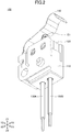
- FIG. 1 and FIG. 2 are perspective views illustrating a configuration of the switch device 100 according to the first embodiment.
- FIG. 3 is an exploded perspective view illustrating the configuration of the switch device 100 according to the first embodiment.
- the switch device 100 is a vehicle switch device.
- the switch device 100 switches between an on-state and an off-state in accordance with the movement of an object present in a vehicle. Accordingly, the switch device 100 can detect the current state of the object.
- the switch device 100 is waterproof, and is suitable for use outside the vehicle.
- the switch device 100 can be used as an opening and closing detection device configured to detect the open/close state of a vehicle's hood, door, trunk, or the like.
- the switch device 100 includes a housing 110, a switch structure 160, and a lever 140.
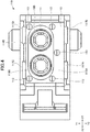
- FIG. 4 is a top view illustrating a configuration of the housing 110.
- FIG. 5 and FIG. 6 are perspective cross-sectional views illustrating the configuration of the housing 110.
- the housing 110 is a molded part formed of a rigid insulating material (such as a resin).
- the switch structure 160 is housed in the housing 110, and the lever 140 is attached to the housing 110.
- the housing 110 is a container having an opening at the top, and the switch structure 160 is housed in the housing 110 through the opening.
- the housing 110 has a first bottom surface 111 and a second bottom surface 112 at the bottom of the housing 110.
- the second bottom surface 112 is provided around the first bottom surface 111 in plan view, and the first bottom surface 111 is deeper than the second bottom surface 112. That is, the outer edge of the second bottom surface 112 is located outward relative to the outer edge of the first bottom surface 111. Therefore, there is a step between the first bottom surface 111 and the second bottom surface 112.
- the first bottom surface 111 has an opening 114A and an opening 114B.
- a lead wire 150A passes through the opening 114A, and a lead wire 150B passes through the opening 114B.
- An annular raised portion 115A is formed around the opening 114A and an annular raised portion 115B is formed around the opening 114B.
- Three or more, in this example, five dome-shaped projections 113 are formed on the second bottom surface 112.
- at least three projections 113 of the three or more projections 113 are not on the same straight line.
- the projections 113 project to the Z1 side, that is, the side opposite to the first bottom surface 111 side (Z2 side).
- the projections 113 are parts of the second bottom surface 112.
- the housing 110 has a side plate 116AB and a side plate 116CD parallel to the ZX plane.
- a fitting hole 118A and a fitting hole 118B are formed in the side plate 116AB.
- an inclined surface 117A and an inclined surface 117B are formed on a surface, facing the side plate 116CD, of the side plate 116AB.
- the inclined surface 117A is located above the fitting hole 118A, and the inclined surface 117B is located above the fitting hole 118B.
- the inclined surface 117A and the inclined surface 117B are inclined away from the side plate 116CD as the inclined surface 117A and the inclined surface 117B approach the upper end of the side plate 116AB.
- a fitting hole 118C and a fitting hole 118D are formed in the side plate 116CD. Further, an inclined surface 117C and an inclined surface 117D are formed on a surface, facing the side plate 116AB, of the side plate 116CD. The inclined surface 117C is located above the fitting hole 118C, and the inclined surface 117D is located above the fitting hole 118D. The inclined surface 117C and the inclined surface 117D are inclined away from the side plate 116AB as the inclined surface 117C and the inclined surface 117D approach the upper end of the side plate 116CD.
- the side plate 116AB and the side plate 116CD are flexible and can be curved in the thickness direction (Y1-Y2 direction) of the side plate 116AB and the side plate 116CD.
- FIG. 7 is a perspective view illustrating a configuration of the switch structure 160.
- FIG. 8A and FIG. 8B are perspective views illustrating a configuration of a switch 120.
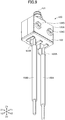
- FIG. 9 is a perspective view illustrating the relationship between the switch 120 and the lead wires 150A and 150B.
- FIG. 10 is a bottom view illustrating the relationship between the housing 110 and the lead wires 150A and 150B.
- the switch structure 160 is housed in the housing 110.
- the switch structure 160 includes the switch 120, a sealing member 130, the lead wire 150A, and the lead wire 150B.
- the switch 120 includes a case 120A, a button 121, a wafer 123, a terminal 122A, and a terminal 122B.
- the case 120A has a substantially rectangular shape having two flat surfaces parallel to the ZX plane and two flat surfaces parallel to the YZ plane. Of the two flat surfaces parallel to the ZX plane, a boss 124A and a boss 124B are formed on the flat surface on the Y2 side of the case 120A, and a boss 124C and a boss 124D are formed on the flat surface on the Y1 side of the case 120A.
- the boss 124A is fitted into the fitting hole 118A
- the boss 124B is fitted into the fitting hole 118B
- the boss 124C is fitted into the fitting hole 118C
- the boss 124D is fitted into the fitting hole 118D.
- the boss 124A through the boss 124D are an example of a fitting projection.
- the terminal 122A and the terminal 122B are flat plate-shaped members that project from the bottom surface of the case 120A.
- the lead wire 150A is electrically and physically connected to the terminal 122A
- the lead wire 150B is electrically and physically connected to the terminal 122B.
- the lead wire 150A and the lead wire 150B are respectively connected to the terminal 122A and the terminal 122B with solder.
- the lead wire 150A and the lead wire 150B may be respectively fixed to the terminal 122A and the terminal 122B by welding.
- the terminal 122A and the terminal 122B are formed of an electrically conductive rigid material (such as a metallic material).
- the button 121 is a member that projects from the top surface of the case 120A of the switch 120 and can be pressed such that the switch 120 switches between an on-state and an off-state. For example, upon the button 121 being pressed, the switch 120 switches the state to the on-state (that is, the terminal 122A is electrically connected to the terminal 122B). Upon the button 121 being released, the switch 120 switches the state to the off-state (that is, the terminal 122A is not electrically connected to the terminal 122B).
- the wafer 123 is provided on the bottom surface of the case 120A, and supports the terminal 122A and the terminal 122B in an upright position. Each of the case 120A and the wafer 123 is a molded part formed of a rigid insulating material (such as a resin).
- the sealing member 130 seals a portion of the lead wire 150A fixed to the terminal 122A and a portion of the lead wire 150B fixed to the terminal 122B.
- the sealing member 130 is elastic.
- the sealing member 130 can include a hot melt adhesive.
- the sealing member 130 includes a base portion 131 and a protruding portion 132.
- the shape of the base portion 131 in the XY plane conforms to the shape of the case 120A in the XY plane, and the protruding portion 132 protrudes downward (to the Z2 side) from the center of the bottom surface of the base portion 131 along the lead wire 150A and the lead wire 150B.
- the base portion 131 has a substantially rectangular shape. Basically, the protruding portion 132 is housed in a space formed by the step between the first bottom surface 111 and the second bottom surface 112. The base portion 131 and the case 120A are housed in a space above the second bottom surface 112.
- the opening 114A is wider than the outer periphery of the lead wire 150A, and the opening 114B is wider than the outer periphery of the lead wire 150B. Therefore, a gap 151A is provided between the opening 114A and the lead wire 150A, and a gap 151B is provided between the opening 114B and the lead wire 150B.
- the lever 140 is a member formed of a metallic material having a thin plate shape.
- the lever 140 extends over the button 121 of the switch 120, and one end of the lever 140 is supported by the housing 110. Upon the other end of the lever 140 being pressed down from the outside, the button 121 of the switch 120 can be pressed down. Note that the lever 140 can be shaped according to the vehicle mode, the object to be detected, and the like.
- the switch structure 160 When the switch structure 160 is placed into the housing 110, first, the lead wire 150A is inserted into the opening 114A, and the lead wire 150B is inserted into the opening 114B. Next, the boss 124A is brought into contact with the inclined surface 117A, the boss 124B is brought into contact with the inclined surface 117B, the boss 124C is brought into contact with the inclined surface 117C, and the boss 124D is brought into contact with the inclined surface 117D.
- the switch structure 160 is pushed further into the housing 110.
- the bosses 124A through 124D move down along the inclined surfaces 117A through 117D, and the side plate 116AB and the side plate 116CD deflect outward.
- the sealing member 130 abuts the projections 113. Because the sealing member 130 is elastic, the sealing member 130 is compressed in the Z1-Z2 direction.
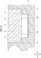
- FIG. 11 is a perspective cross-sectional view illustrating the relationship between the sealing member 130 and the housing 110 into which the switch 120 is snap-fitted.
- FIG. 12 is a front cross-sectional view illustrating the relationship between the sealing member 130 and the housing 110 into which the switch 120 is snap-fitted.
- the bottom surface of the base portion 131 abuts the projections 113 provided on the second bottom surface 112, and portions, abutting the projections 113, of the base portion 131 are recessed. That is, the sealing member 130 is compressed in the Z1-Z2 direction between the switch 120 and the second bottom surface 112. Further, the vicinities of the portions, pushed up by the projections 113, of the bottom surface of the base portion 131 are spaced apart from the second bottom surface 112. Thus, a second space 162 is provided between the second bottom surface 112 and the bottom surface of the base portion 131.
- the upper surfaces of the raised portion 115A and the raised portion 115B are spaced apart from the bottom surface of the protruding portion 132.
- a first space 161 is provided between the upper surfaces of the raised portions 115A and 115B and the bottom surface of the protruding portion 132.
- the second bottom surface 112 may have a drain passage such as a groove connecting the outer edge and the inner edge of the second bottom surface 112 in plan view.
- a space in such a drain passage may also function as the second space.
- the first bottom surface 111 may have a drain passage such as a groove leading to the opening 114A or the opening 114B.
- a space in such a drain passage may also function as the first space.
- an opening for drainage may be formed in the first bottom surface 111.
- the opening 114A through which the lead wire 150A passes and the opening 114B through which the lead wire 150B passes are formed in the first bottom surface 111, and the sealing member 130 abuts the second bottom surface 112. Further, the second bottom surface 112 is located closer to the switch 120 than the first bottom surface 111. With this configuration, even if water enters the housing 110, the water can be discharged from the first bottom surface 111, through the gap 151A between the opening 114A and the lead wire 150A and the gap 151B between the opening 114B and the lead wire 150B, to the outside.
- the lead wire 150A and the lead wire 150B are subjected to tensile loads in various directions.
- the adhesion between the sealing member 130 and the lead wires 150A and 150B can be well maintained, and the adhesion between the sealing member 130 and the switch 120 can also be well maintained.
- the switch 120 causes the sealing member 130 to be compressed against the second bottom surface 112 because the lead wire 150A and the lead wire 150B are fixed to the terminal 122A and the terminal 122B with solder or the like.
- the lead wire 150A and the lead wire 150B are not readily removed from the sealing member 130, and the sealing member 130 is not readily removed from the switch 120. Further, if the lead wire 150A and the lead wire 150B are subjected to a tensile load in a given direction in the XY plane, this tensile load is converted into a tensile load in the Z2 direction within the opening 114A and the opening 114B.
- the lead wire 150A and the lead wire 150B are subjected to the tensile load in the Z2 direction, because the fixed portions are reinforced with solder or the like, the lead wire 150A and the lead wire 150B are not readily removed from the sealing member 130, and the sealing member 130 is not readily removed from the switch 120. Accordingly, it is possible to improve the strength against tensile loads in various directions while maintaining waterproofness.
- the second bottom surface 112 is provided around the first bottom surface 111, and the outer edge of the second bottom surface 112 is located outward relative to the outer edge of the first bottom surface 111. Accordingly, the switch structure 160 can be readily placed into the housing 110 from above the housing 110.
- first space 161 is provided between the sealing member 130 and the first bottom surface 111, water entering the housing 110 can be securely discharged to the outside.
- the first bottom surface 111 may have a drain passage leading to a space outside the housing 110. Accordingly, water entering the housing 110 can be securely discharged to the outside through the drain passage.
- the sealing member 130 is elastic, and the switch 120 is snap-fitted into the housing 110 with the sealing member 130 being compressed between the switch 120 and the second bottom surface 112. Accordingly, the sealing member 130 adheres firmly to the switch 120. Therefore, even if a tensile load is applied to the lead wire 150A and the lead wire 150B, the sealing member 130 is highly unlikely to be removed from the switch 120, thus providing excellent waterproofness.
- the housing 110 has the side plate 116AB and the side plate 116CD.
- the side plate 116AB and the side plate 116CD contact the side surfaces of the switch 120, the side plate 116AB has the fitting hole 118A and the fitting hole 118B, and the side plate 116CD has the fitting hole 118C and the fitting hole 118D.
- the switch 120 has the bosses 124A through 124D on the side surfaces of the switch 120, and the bosses 124A through 124D are fitted into the fitting holes 118A through 118D. With this configuration, the switch 120 can be more securely snap-fitted into the housing 110.
- the second space 162 is provided between the second bottom surface 112 and the sealing member 130. Accordingly, water entering the housing 110 can be readily discharged from the second bottom surface 112 toward the first bottom surface 111.
- the second bottom surface 112 has the projections 113 that project to the side (Z1 side) opposite to the first bottom surface 111 side (Z2 side), and the sealing member 130 abuts the projections 113. Accordingly, the second space 162 can be secured between the second bottom surface 112 and the sealing member 130. In addition, the projections 113 push the sealing member 130 up, thus improving the adhesion strength between the sealing member 130 and the switch 120.
- FIG. 13 is a perspective view of the exterior of an opening and closing detection device 200 (when the hood of a vehicle is open) according to the second embodiment.
- FIG. 14 is a perspective view of the exterior of the opening and closing detection device 200 (when the hood of the vehicle is closed) according to the second embodiment.
- the opening and closing detection device 200 is configured to detect the open/close state of the hood of the vehicle. As illustrated in FIG. 13 , the opening and closing detection device 200 includes the switch device 100 according to the first embodiment, a base plate 210, and a cam plate 220.
- the base plate 210 is a member formed of a metallic material having a thin plate shape.
- the base plate 210 fixes the switch device 100 to the vicinity of the hood of the vehicle.
- the base plate 210 rotatably supports the cam plate 220.
- the base plate 210 can be shaped according to the vehicle model, the installation position, and the like. That is, the opening and closing detection device 200 according to the present embodiment can be applied to any of a plurality of vehicle models and used at any of a plurality of installation positions by appropriately changing the shape of the base plate 210.
- the base plate 210 is an example of a fixing member.
- the cam plate 220 is a member formed of a metallic material having a thin plate shape.
- a shaft 220A of the cam plate 220 is supported by the base plate 210. Therefore, the cam plate 220 is rotatable about the shaft 220A.
- the cam plate 220 includes a U-shaped lever 222 capable of engaging a striker 300 of the hood. Therefore, the cam plate 220 is rotatable upon the lever 222 being moved by the striker 300 at the time of opening or closing of the hood.
- the cam plate 220 further includes a cam portion 221 that projects radially relative to the other portions of the cam plate 220. The cam portion 221 presses the lever 140 of the switch device 100 down as the cam plate 220 rotates. With this configuration, the cam plate 220 can convert an opening and closing movement of the hood into a switching movement of the switch 120 of the switch device 100.
- the cam plate 220 is an example of a conversion member.
- the lever 222 of the cam plate 220 engages the striker 300 of the hood.
- the cam plate 220 is maintained at a predetermined angle of rotation.
- the cam portion 221 of the cam plate 220 is in a position where the cam portion 221 does not press the lever 140 of the switch device 100 down. Accordingly, the switch device 100 is in the off-position.
- the switch device according to the present invention is applied to the opening and closing detection device 200 configured to detect the open/close state of the hood of the vehicle; however, the present invention is not limited thereto.
- the switch device according to the present invention may be applied to any other detection device configured to detect the state of a door (such as a trunk) other than the hood of the vehicle.
- the switch device according to the present invention is not necessarily applied to the vehicle, and may be applied to any other device (such as an aircraft, a ship, an industrial machine, or a home appliance).
- the lever 140 is not necessarily provided depending on a device to which the switch device 100 is applied (that is, the button 121 of the switch 120 may be directly pressed from the outside).
- a switch including three or more terminals may be used instead of the switch 120 including the two terminals, and the number of lead wires may be changed accordingly.
- any other type of switch such as a toggle switch or a rocker switch
- the switch 120 push button switch
Landscapes
- Engineering & Computer Science (AREA)
- Microelectronics & Electronic Packaging (AREA)
- Switch Cases, Indication, And Locking (AREA)
- Push-Button Switches (AREA)
- Rotary Switch, Piano Key Switch, And Lever Switch (AREA)
Abstract
Description
- The present invention relates to a switch device, and an opening and closing detection device.
- Conventionally, in vehicles such as automobiles, switch devices disposed in the vicinities of objects to detect the current states of the objects are known. For example, whether the hood of a vehicle is open or closed can be detected by disposing such a switch device in the vicinity of the hood. If such a switch device is disposed outside a vehicle, the switch device is required to be waterproof so as to prevent the switch device from malfunctioning or being damaged.
- For example, Patent Document 1 discloses a technology in which a plurality of projections and recesses are formed on the surface of an outer jacket of a cable such that adhesion between the cable and a filler can be improved. Further, Patent Document 2 discloses a technology related to a seal structure for a multi-core cable.
-
- Patent Document 1:
Japanese Unexamined Utility Model Application Publication No. 59-45815 - Patent Document 2: Japanese Laid-open Patent
- Publication No.
2016-122595 - However, the technology disclosed in Patent Document 1 cannot provide sufficient waterproofness, and thus, there are concerns that water entering a switch device may cause the switch device to malfunction or to be damaged. In addition, even if the technology described in Patent Document 2 is directly applied to a switch device, sufficient waterproofness is unlikely to be provided.
- It is an object of the present disclosure to provide a switch device with excellent waterproofness, and an opening and closing detection device.
- According to an embodiment of the present disclosure, a switch device including a switch, a lead wire, a sealing member, and a housing is provided. The switch includes a terminal provided on the outer side of the switch, the lead wire is fixed to the terminal, the sealing member seals a portion of the lead wire fixed to the terminal, and the housing is configured to house the sealing member. The housing has a first bottom surface and a second bottom surface. The first bottom surface has an opening through which the lead wire passes, and the second bottom surface is located closer to the switch than the first bottom surface. The sealing member abuts the second bottom surface.
- According to the present disclosure, excellent waterproofness can be provided.
-
-
FIG. 1 is a perspective view (part 1) illustrating a configuration of a switch device according to a first embodiment; -
FIG. 2 is a perspective view (part 2) illustrating the configuration of the switch device according to the first embodiment; -
FIG. 3 is an exploded perspective view illustrating the configuration of the switch device according to the first embodiment; -
FIG. 4 is a top view illustrating a configuration of a housing; -
FIG. 5 is a perspective cross-sectional view (part 1) illustrating the configuration of the housing; -
FIG. 6 is a perspective cross-sectional view (part 2) illustrating the configuration of the housing; -
FIG. 7 is a perspective view illustrating a configuration of a switch structure; -
FIG. 8A is a perspective view illustrating a configuration of a switch; -
FIG. 8B is a perspective view illustrating the configuration of the switch; -
FIG. 9 is a perspective view illustrating the relationship between the switch and lead wires; -
FIG. 10 is a bottom view illustrating the relationship between the housing and the lead wires; -
FIG. 11 is a perspective cross-sectional view illustrating the relationship between a sealing member and the housing into which the switch is snap-fitted; -
FIG. 12 is a front cross-sectional view illustrating the relationship between the sealing member and the housing into which the switch is snap-fitted; -
FIG. 13 is a perspective view of the exterior of an opening and closing detection device (when the hood of a vehicle is open) according to a second embodiment; -
FIG. 14 is a perspective view of the exterior of the opening and closing detection device (when the hood of the vehicle is closed) according to the second embodiment. - The inventors have made earnest investigations such that excellent waterproofness can be obtained. As a result of the investigations, the inventors have found that placing a switch into a housing while pressing the switch against the bottom surface of the housing is effective in improving waterproofness. However, the inventors have also found that, if the entire bottom surface of the switch contacts the bottom surface of the housing, water entering the housing may be unable to be discharged, and thus, it may be difficult to obtain desired waterproofness. The present invention is made based on such new findings.
- In the following, embodiments of the present invention will be described in detail with reference to the accompanying drawings. In the specification and the drawings, elements having substantially the same functions or configurations are denoted by the same reference numerals, and the description thereof will not be repeated. In the present disclosure, an X1-X2 direction, a Y1-Y2 direction, and a Z1-Z2 direction are perpendicular to each other. Further, a plane including the X1-X2 direction and the Y1-Y2 direction is referred to as an XY-plane, a plane including the Y1-Y2 direction and the Z1-Z2 direction is referred to as a YZ-plane, and a plane including the Z1-Z2 direction and the X1-X2 direction is referred to as a ZX-plane. For convenience, the Z1-Z2 direction is the vertical direction. A plan view means that an object is viewed from the Z1 side.
- A first embodiment will be described first. The first embodiment relates to a switch device.
FIG. 1 andFIG. 2 are perspective views illustrating a configuration of theswitch device 100 according to the first embodiment.FIG. 3 is an exploded perspective view illustrating the configuration of theswitch device 100 according to the first embodiment. - The
switch device 100 according to the first embodiment is a vehicle switch device. Theswitch device 100 switches between an on-state and an off-state in accordance with the movement of an object present in a vehicle. Accordingly, theswitch device 100 can detect the current state of the object. Theswitch device 100 is waterproof, and is suitable for use outside the vehicle. For example, theswitch device 100 can be used as an opening and closing detection device configured to detect the open/close state of a vehicle's hood, door, trunk, or the like. - As illustrated in
FIG. 1 through FIG. 3 , theswitch device 100 includes ahousing 110, aswitch structure 160, and alever 140. -
FIG. 4 is a top view illustrating a configuration of thehousing 110.FIG. 5 andFIG. 6 are perspective cross-sectional views illustrating the configuration of thehousing 110. - The
housing 110 is a molded part formed of a rigid insulating material (such as a resin). Theswitch structure 160 is housed in thehousing 110, and thelever 140 is attached to thehousing 110. Thehousing 110 is a container having an opening at the top, and theswitch structure 160 is housed in thehousing 110 through the opening. - The
housing 110 has a firstbottom surface 111 and a secondbottom surface 112 at the bottom of thehousing 110. The secondbottom surface 112 is provided around the firstbottom surface 111 in plan view, and the firstbottom surface 111 is deeper than the secondbottom surface 112. That is, the outer edge of the secondbottom surface 112 is located outward relative to the outer edge of the firstbottom surface 111. Therefore, there is a step between the firstbottom surface 111 and the secondbottom surface 112. The firstbottom surface 111 has anopening 114A and anopening 114B. Alead wire 150A passes through theopening 114A, and alead wire 150B passes through theopening 114B. An annular raisedportion 115A is formed around theopening 114A and an annular raisedportion 115B is formed around theopening 114B. Three or more, in this example, five dome-shapedprojections 113 are formed on the secondbottom surface 112. For example, at least threeprojections 113 of the three ormore projections 113 are not on the same straight line. Theprojections 113 project to the Z1 side, that is, the side opposite to the firstbottom surface 111 side (Z2 side). Theprojections 113 are parts of the secondbottom surface 112. - The
housing 110 has a side plate 116AB and a side plate 116CD parallel to the ZX plane. Afitting hole 118A and afitting hole 118B are formed in the side plate 116AB. Further, aninclined surface 117A and aninclined surface 117B are formed on a surface, facing the side plate 116CD, of the side plate 116AB. Theinclined surface 117A is located above thefitting hole 118A, and theinclined surface 117B is located above thefitting hole 118B. Theinclined surface 117A and theinclined surface 117B are inclined away from the side plate 116CD as theinclined surface 117A and theinclined surface 117B approach the upper end of the side plate 116AB. Afitting hole 118C and afitting hole 118D are formed in the side plate 116CD. Further, aninclined surface 117C and aninclined surface 117D are formed on a surface, facing the side plate 116AB, of the side plate 116CD. Theinclined surface 117C is located above thefitting hole 118C, and theinclined surface 117D is located above thefitting hole 118D. Theinclined surface 117C and theinclined surface 117D are inclined away from the side plate 116AB as theinclined surface 117C and theinclined surface 117D approach the upper end of the side plate 116CD. The side plate 116AB and the side plate 116CD are flexible and can be curved in the thickness direction (Y1-Y2 direction) of the side plate 116AB and the side plate 116CD. -
FIG. 7 is a perspective view illustrating a configuration of theswitch structure 160.FIG. 8A andFIG. 8B are perspective views illustrating a configuration of aswitch 120.FIG. 9 is a perspective view illustrating the relationship between theswitch 120 and thelead wires FIG. 10 is a bottom view illustrating the relationship between thehousing 110 and thelead wires - As described above, the
switch structure 160 is housed in thehousing 110. Theswitch structure 160 includes theswitch 120, a sealingmember 130, thelead wire 150A, and thelead wire 150B. - The
switch 120 includes acase 120A, abutton 121, awafer 123, aterminal 122A, and a terminal 122B. Thecase 120A has a substantially rectangular shape having two flat surfaces parallel to the ZX plane and two flat surfaces parallel to the YZ plane. Of the two flat surfaces parallel to the ZX plane, aboss 124A and aboss 124B are formed on the flat surface on the Y2 side of thecase 120A, and aboss 124C and aboss 124D are formed on the flat surface on the Y1 side of thecase 120A. Theboss 124A is fitted into thefitting hole 118A, theboss 124B is fitted into thefitting hole 118B, theboss 124C is fitted into thefitting hole 118C, and theboss 124D is fitted into thefitting hole 118D. Theboss 124A through theboss 124D are an example of a fitting projection. - The terminal 122A and the terminal 122B are flat plate-shaped members that project from the bottom surface of the
case 120A. Thelead wire 150A is electrically and physically connected to the terminal 122A, and thelead wire 150B is electrically and physically connected to the terminal 122B. For example, thelead wire 150A and thelead wire 150B are respectively connected to the terminal 122A and the terminal 122B with solder. Thelead wire 150A and thelead wire 150B may be respectively fixed to the terminal 122A and the terminal 122B by welding. The terminal 122A and the terminal 122B are formed of an electrically conductive rigid material (such as a metallic material). Thebutton 121 is a member that projects from the top surface of thecase 120A of theswitch 120 and can be pressed such that theswitch 120 switches between an on-state and an off-state. For example, upon thebutton 121 being pressed, theswitch 120 switches the state to the on-state (that is, theterminal 122A is electrically connected to the terminal 122B). Upon thebutton 121 being released, theswitch 120 switches the state to the off-state (that is, theterminal 122A is not electrically connected to the terminal 122B). Thewafer 123 is provided on the bottom surface of thecase 120A, and supports the terminal 122A and the terminal 122B in an upright position. Each of thecase 120A and thewafer 123 is a molded part formed of a rigid insulating material (such as a resin). - The sealing
member 130 seals a portion of thelead wire 150A fixed to the terminal 122A and a portion of thelead wire 150B fixed to the terminal 122B. The sealingmember 130 is elastic. For example, the sealingmember 130 can include a hot melt adhesive. The sealingmember 130 includes abase portion 131 and a protrudingportion 132. The shape of thebase portion 131 in the XY plane conforms to the shape of thecase 120A in the XY plane, and the protrudingportion 132 protrudes downward (to the Z2 side) from the center of the bottom surface of thebase portion 131 along thelead wire 150A and thelead wire 150B. Thebase portion 131 has a substantially rectangular shape. Basically, the protrudingportion 132 is housed in a space formed by the step between the firstbottom surface 111 and the secondbottom surface 112. Thebase portion 131 and thecase 120A are housed in a space above the secondbottom surface 112. - The
opening 114A is wider than the outer periphery of thelead wire 150A, and theopening 114B is wider than the outer periphery of thelead wire 150B. Therefore, agap 151A is provided between theopening 114A and thelead wire 150A, and agap 151B is provided between the opening 114B and thelead wire 150B. - The
lever 140 is a member formed of a metallic material having a thin plate shape. Thelever 140 extends over thebutton 121 of theswitch 120, and one end of thelever 140 is supported by thehousing 110. Upon the other end of thelever 140 being pressed down from the outside, thebutton 121 of theswitch 120 can be pressed down. Note that thelever 140 can be shaped according to the vehicle mode, the object to be detected, and the like. - In the following, a method for placing the
switch structure 160 into thehousing 110 will be described. - When the
switch structure 160 is placed into thehousing 110, first, thelead wire 150A is inserted into theopening 114A, and thelead wire 150B is inserted into theopening 114B. Next, theboss 124A is brought into contact with theinclined surface 117A, theboss 124B is brought into contact with theinclined surface 117B, theboss 124C is brought into contact with theinclined surface 117C, and theboss 124D is brought into contact with theinclined surface 117D. - In this state, the
switch structure 160 is pushed further into thehousing 110. As a result, thebosses 124A through 124D move down along theinclined surfaces 117A through 117D, and the side plate 116AB and the side plate 116CD deflect outward. Upon theswitch structure 160 being pushed further into thehousing 110, the sealingmember 130 abuts theprojections 113. Because the sealingmember 130 is elastic, the sealingmember 130 is compressed in the Z1-Z2 direction. - In this state, upon the
switch structure 160 being pushed further into thehousing 110, theboss 124A is fitted into thefitting hole 118A, theboss 124B is fitted into thefitting hole 118B, theboss 124C is fitted into thefitting hole 118C, and theboss 124D is fitted into thefitting hole 118D. As a result, the outward pressure exerted on the side plate 116AB and the side plate 116CD by thebosses 124A through 124D is released, and theswitch 120 is snap-fitted into thehousing 110. When pressing theswitch structure 160 is stopped, the sealingmember 130 compressed in the Z1-Z2 direction attempts to return to the original shape. However, because thebosses 124A through 124D are fitted into thefitting holes 118A through 118D, the sealingmember 130 remains compressed. Accordingly, the sealingmember 130 adheres firmly to thewafer 123 of theswitch 120. -
FIG. 11 is a perspective cross-sectional view illustrating the relationship between the sealingmember 130 and thehousing 110 into which theswitch 120 is snap-fitted.FIG. 12 is a front cross-sectional view illustrating the relationship between the sealingmember 130 and thehousing 110 into which theswitch 120 is snap-fitted. - As illustrated in
FIG. 11 andFIG. 12 , the bottom surface of thebase portion 131 abuts theprojections 113 provided on the secondbottom surface 112, and portions, abutting theprojections 113, of thebase portion 131 are recessed. That is, the sealingmember 130 is compressed in the Z1-Z2 direction between theswitch 120 and the secondbottom surface 112. Further, the vicinities of the portions, pushed up by theprojections 113, of the bottom surface of thebase portion 131 are spaced apart from the secondbottom surface 112. Thus, asecond space 162 is provided between the secondbottom surface 112 and the bottom surface of thebase portion 131. In addition, the upper surfaces of the raisedportion 115A and the raisedportion 115B are spaced apart from the bottom surface of the protrudingportion 132. Thus, afirst space 161 is provided between the upper surfaces of the raisedportions portion 132. - Note that the second
bottom surface 112 may have a drain passage such as a groove connecting the outer edge and the inner edge of the secondbottom surface 112 in plan view. A space in such a drain passage may also function as the second space. - Further, the first
bottom surface 111 may have a drain passage such as a groove leading to theopening 114A or theopening 114B. A space in such a drain passage may also function as the first space. Further, in addition to theopening 114A and theopening 114B, an opening for drainage may be formed in the firstbottom surface 111. - As described above, in the
switch device 100 according to the first embodiment, theopening 114A through which thelead wire 150A passes and theopening 114B through which thelead wire 150B passes are formed in the firstbottom surface 111, and the sealingmember 130 abuts the secondbottom surface 112. Further, the secondbottom surface 112 is located closer to theswitch 120 than the firstbottom surface 111. With this configuration, even if water enters thehousing 110, the water can be discharged from the firstbottom surface 111, through thegap 151A between theopening 114A and thelead wire 150A and thegap 151B between the opening 114B and thelead wire 150B, to the outside. - Further, on the outside of the
housing 110, thelead wire 150A and thelead wire 150B are subjected to tensile loads in various directions. However, the adhesion between the sealingmember 130 and thelead wires member 130 and theswitch 120 can also be well maintained. For example, if thelead wire 150A and thelead wire 150B are subjected to a tensile load in the Z2 direction, theswitch 120 causes the sealingmember 130 to be compressed against the secondbottom surface 112 because thelead wire 150A and thelead wire 150B are fixed to the terminal 122A and the terminal 122B with solder or the like. Therefore, as the fixed portions are reinforced with solder or the like, thelead wire 150A and thelead wire 150B are not readily removed from the sealingmember 130, and the sealingmember 130 is not readily removed from theswitch 120. Further, if thelead wire 150A and thelead wire 150B are subjected to a tensile load in a given direction in the XY plane, this tensile load is converted into a tensile load in the Z2 direction within theopening 114A and theopening 114B. Therefore, similar to the above case where thelead wire 150A and thelead wire 150B are subjected to the tensile load in the Z2 direction, because the fixed portions are reinforced with solder or the like, thelead wire 150A and thelead wire 150B are not readily removed from the sealingmember 130, and the sealingmember 130 is not readily removed from theswitch 120. Accordingly, it is possible to improve the strength against tensile loads in various directions while maintaining waterproofness. - Further, in plan view, the second
bottom surface 112 is provided around the firstbottom surface 111, and the outer edge of the secondbottom surface 112 is located outward relative to the outer edge of the firstbottom surface 111. Accordingly, theswitch structure 160 can be readily placed into thehousing 110 from above thehousing 110. - Further, because the
first space 161 is provided between the sealingmember 130 and the firstbottom surface 111, water entering thehousing 110 can be securely discharged to the outside. - Further, the first
bottom surface 111 may have a drain passage leading to a space outside thehousing 110. Accordingly, water entering thehousing 110 can be securely discharged to the outside through the drain passage. - Further, the sealing
member 130 is elastic, and theswitch 120 is snap-fitted into thehousing 110 with the sealingmember 130 being compressed between theswitch 120 and the secondbottom surface 112. Accordingly, the sealingmember 130 adheres firmly to theswitch 120. Therefore, even if a tensile load is applied to thelead wire 150A and thelead wire 150B, the sealingmember 130 is highly unlikely to be removed from theswitch 120, thus providing excellent waterproofness. - Further, the
housing 110 has the side plate 116AB and the side plate 116CD. The side plate 116AB and the side plate 116CD contact the side surfaces of theswitch 120, the side plate 116AB has thefitting hole 118A and thefitting hole 118B, and the side plate 116CD has thefitting hole 118C and thefitting hole 118D. Theswitch 120 has thebosses 124A through 124D on the side surfaces of theswitch 120, and thebosses 124A through 124D are fitted into thefitting holes 118A through 118D. With this configuration, theswitch 120 can be more securely snap-fitted into thehousing 110. - Further, the
second space 162 is provided between the secondbottom surface 112 and the sealingmember 130. Accordingly, water entering thehousing 110 can be readily discharged from the secondbottom surface 112 toward the firstbottom surface 111. - Further, the second
bottom surface 112 has theprojections 113 that project to the side (Z1 side) opposite to the firstbottom surface 111 side (Z2 side), and the sealingmember 130 abuts theprojections 113. Accordingly, thesecond space 162 can be secured between the secondbottom surface 112 and the sealingmember 130. In addition, theprojections 113 push the sealingmember 130 up, thus improving the adhesion strength between the sealingmember 130 and theswitch 120. - Next, a second embodiment will be described. The second embodiment relates to an opening and closing detection device that includes the
switch device 100.FIG. 13 is a perspective view of the exterior of an opening and closing detection device 200 (when the hood of a vehicle is open) according to the second embodiment.FIG. 14 is a perspective view of the exterior of the opening and closing detection device 200 (when the hood of the vehicle is closed) according to the second embodiment. - The opening and
closing detection device 200 according to the second embodiment is configured to detect the open/close state of the hood of the vehicle. As illustrated inFIG. 13 , the opening andclosing detection device 200 includes theswitch device 100 according to the first embodiment, abase plate 210, and acam plate 220. - The
base plate 210 is a member formed of a metallic material having a thin plate shape. Thebase plate 210 fixes theswitch device 100 to the vicinity of the hood of the vehicle. In addition, thebase plate 210 rotatably supports thecam plate 220. Thebase plate 210 can be shaped according to the vehicle model, the installation position, and the like. That is, the opening andclosing detection device 200 according to the present embodiment can be applied to any of a plurality of vehicle models and used at any of a plurality of installation positions by appropriately changing the shape of thebase plate 210. Thebase plate 210 is an example of a fixing member. - The
cam plate 220 is a member formed of a metallic material having a thin plate shape. Ashaft 220A of thecam plate 220 is supported by thebase plate 210. Therefore, thecam plate 220 is rotatable about theshaft 220A. Thecam plate 220 includes aU-shaped lever 222 capable of engaging astriker 300 of the hood. Therefore, thecam plate 220 is rotatable upon thelever 222 being moved by thestriker 300 at the time of opening or closing of the hood. Thecam plate 220 further includes acam portion 221 that projects radially relative to the other portions of thecam plate 220. Thecam portion 221 presses thelever 140 of theswitch device 100 down as thecam plate 220 rotates. With this configuration, thecam plate 220 can convert an opening and closing movement of the hood into a switching movement of theswitch 120 of theswitch device 100. Thecam plate 220 is an example of a conversion member. - As illustrated in
FIG. 13 , when the hood is closed, thelever 222 of thecam plate 220 engages thestriker 300 of the hood. Thus, thecam plate 220 is maintained at a predetermined angle of rotation. In this state, thecam portion 221 of thecam plate 220 is in a position where thecam portion 221 does not press thelever 140 of theswitch device 100 down. Accordingly, theswitch device 100 is in the off-position. - Conversely, as illustrated in
FIG. 14 , when the hood is open, thestriker 300 of the hood is pulled up, thus causing thelever 222 of thecam plate 220 to be pulled up. As a result, thecam plate 220 rotates clockwise about theshaft 220A, and thecam portion 221 of thecam plate 220 presses thelever 140 of theswitch device 100 down. Accordingly, theswitch device 100 is in the on-position. - Although the embodiments of the present invention have been described in detail above, the present invention is not limited to the particulars of the above-described embodiments. Variations and replacements may be applied to the above-described embodiments without departing from the scope of the present invention.
- Further, in the above-described embodiments, the switch device according to the present invention is applied to the opening and
closing detection device 200 configured to detect the open/close state of the hood of the vehicle; however, the present invention is not limited thereto. For example, the switch device according to the present invention may be applied to any other detection device configured to detect the state of a door (such as a trunk) other than the hood of the vehicle. Further, the switch device according to the present invention is not necessarily applied to the vehicle, and may be applied to any other device (such as an aircraft, a ship, an industrial machine, or a home appliance). - Further, for example, in the
switch device 100 according to the above-described embodiments, thelever 140 is not necessarily provided depending on a device to which theswitch device 100 is applied (that is, thebutton 121 of theswitch 120 may be directly pressed from the outside). - Further, for example, in the
switch device 100 according to the above-described embodiments, a switch including three or more terminals may be used instead of theswitch 120 including the two terminals, and the number of lead wires may be changed accordingly. - Further, for example, in the
switch device 100 according to the above-described embodiments, any other type of switch (such as a toggle switch or a rocker switch) may be used instead of the switch 120 (push button switch). - The present application is based on and claims priority to
Japanese Patent Application No. 2019-040372, filed on March 6, 2019 -
- 100 switch device
- 110 housing
- 111 first bottom surface
- 112 second bottom surface
- 113 projection
- 114A, 114B opening
- 115A, 115B raised portion
- 116AB, 116CD side plate
- 117A, 117B, 117C, 117D inclined surface
- 118A, 118B, 118C, 118D fitting hole
- 120 switch
- 120A case
- 121 button
- 122A, 122B terminal
- 123 wafer
- 124A, 124B, 124C, 124D boss
- 130 sealing member
- 131 base portion
- 132 protruding portion
- 140 lever
- 150A, 150B lead wire
- 151A, 151B gap
- 160 switch structure
- 161 first space
- 162 second space
- 200 opening and closing detection device
- 210 base plate (fixing member)
- 220 cam plate (conversion member)
- 220A shaft
- 221 cam portion
- 222 lever
- 300 striker
Claims (11)
- A switch device comprising:a switch including a terminal provided on an outer side of the switch;a lead wire fixed to the terminal;a sealing member that seals a portion of the lead wire fixed to the terminal; anda housing configured to house the sealing member,wherein the housing has a first bottom surface and a second bottom surface, the first bottom surface having an opening through which the lead wire passes, and the second bottom surface being located closer to the switch than the first bottom surface, andthe sealing member abuts the second bottom surface.
- The switch device according to claim 1, wherein an outer edge of the second bottom surface is located outward relative to an outer edge of the first bottom surface.
- The switch device according to claim 1 or 2, wherein a first space is provided between the sealing member and the first bottom surface.
- The switch device according to any one of claims 1 to 3, wherein the first bottom surface has a drain passage leading to a space outside the housing.
- The switch device according to any one of claims 1 to 4, wherein the sealing member is elastic, and the switch is snap-fitted into the housing as the sealing member is compressed between the switch and the second bottom surface.
- The switch device according to claim 5, wherein the housing has a side plate, the side plate contacting a side surface of the switch and having a fitting hole, and
the switch has a fitting projection on the side surface of the switch, the fitting projection being fitted into the fitting hole. - The switch device according to any one of claims 1 to 6, wherein the sealing member includes a hot melt adhesive.
- The switch device according to any one of claims 1 to 7, wherein a second space is provided between the second bottom surface and the sealing member.
- The switch device according to any one of claims 1 to 8, wherein the second bottom surface has a projection that projects to a side opposite to a first bottom surface side, and
the sealing member abuts the projection. - An opening and closing detection device comprising:the switch device according to any one of claims 1 to 9;a fixing member configured to fix the switch device to a vicinity of a door; anda conversion member disposed between the door and the switch device to convert an opening and closing movement of the door into a switching movement of the switch.
- The opening and closing detection device according to claim 10, wherein the door is a hood of a vehicle.
Applications Claiming Priority (2)
| Application Number | Priority Date | Filing Date | Title |
|---|---|---|---|
| JP2019040372 | 2019-03-06 | ||
| PCT/JP2020/003308 WO2020179289A1 (en) | 2019-03-06 | 2020-01-30 | Switch device and opening and closing detection device |
Publications (3)
| Publication Number | Publication Date |
|---|---|
| EP3937202A1 true EP3937202A1 (en) | 2022-01-12 |
| EP3937202A4 EP3937202A4 (en) | 2023-04-19 |
| EP3937202B1 EP3937202B1 (en) | 2024-07-17 |
Family
ID=72338293
Family Applications (1)
| Application Number | Title | Priority Date | Filing Date |
|---|---|---|---|
| EP20766347.7A Active EP3937202B1 (en) | 2019-03-06 | 2020-01-30 | Switch device and opening and closing detection device |
Country Status (5)
| Country | Link |
|---|---|
| US (1) | US11862425B2 (en) |
| EP (1) | EP3937202B1 (en) |
| JP (1) | JP7182688B2 (en) |
| CN (1) | CN113519035B (en) |
| WO (1) | WO2020179289A1 (en) |
Family Cites Families (30)
| Publication number | Priority date | Publication date | Assignee | Title |
|---|---|---|---|---|
| US2785251A (en) * | 1953-06-16 | 1957-03-12 | Robert J Cassidy | Sealed electrical switches |
| US3612801A (en) * | 1970-06-23 | 1971-10-12 | Cutler Hammer Inc | Contact pin wire termination adaptor assembly for electric switches |
| US3781456A (en) * | 1972-08-01 | 1973-12-25 | Atlantic Richfield Co | Pressure sealed cable packoff and method for making and using same |
| US4103136A (en) * | 1977-05-17 | 1978-07-25 | Allen-Bradley Company | Switch housing with cable seal |
| JPS5531262U (en) * | 1978-08-22 | 1980-02-28 | ||
| JPS6029784Y2 (en) * | 1979-03-27 | 1985-09-07 | オムロン株式会社 | Sealed electrical equipment |
| US4255638A (en) * | 1979-04-13 | 1981-03-10 | Alco Electronic Products, Inc. | Miniature switch, sealed for soldering, with handle housing exposed |
| JPS57143627U (en) * | 1981-03-04 | 1982-09-09 | ||
| JPS5945815U (en) | 1982-09-16 | 1984-03-27 | 株式会社山武 | Limit switch cable holding device |
| US4476360A (en) * | 1982-12-15 | 1984-10-09 | Eaton Corporation | Terminal seal for electric switch |
| JPS6024026U (en) * | 1983-07-25 | 1985-02-19 | 東北金属工業株式会社 | Micro switch cover |
| DE8411211U1 (en) * | 1984-04-10 | 1988-09-08 | Barlian, Reinhold, Dipl.-Ing. (FH), 6990 Bad Mergentheim | Limit switch |
| US4555686A (en) * | 1984-05-29 | 1985-11-26 | Texas Instruments Incorporated | Snap-acting thermostatic switch assembly |
| CA2084119C (en) * | 1992-06-18 | 1995-12-12 | David W. Keck | Hermetically sealed snap switch arrangement |
| JP3038283B2 (en) * | 1993-06-15 | 2000-05-08 | アルプス電気株式会社 | Switch device |
| JP3522357B2 (en) * | 1994-09-19 | 2004-04-26 | 日本特殊陶業株式会社 | Oxygen sensor |
| US5734103A (en) * | 1996-09-13 | 1998-03-31 | Badger Meter, Inc. | Sealed wire entry for instrument housing and method of sealing |
| DE19757023B4 (en) * | 1997-12-20 | 2007-06-06 | Bernstein Ag | Switching device with explosion protection |
| US6008458A (en) * | 1998-03-30 | 1999-12-28 | C & K Components, Inc. | Sealed slide switch |
| DE29905589U1 (en) * | 1999-03-26 | 1999-06-10 | Hans Bernstein GmbH & Co., 32457 Porta Westfalica | switch |
| JP4473141B2 (en) * | 2005-01-04 | 2010-06-02 | 日立オートモティブシステムズ株式会社 | Electronic control unit |
| KR101241629B1 (en) * | 2008-05-30 | 2013-03-11 | 가부시키가이샤 우부카타 세이사쿠쇼 | Thermally-actuated switch |
| DE102009053145A1 (en) * | 2009-11-05 | 2011-05-12 | Phoenix Contact Gmbh & Co. Kg | Overvoltage protection device, has thermal expandable material arranged within housing such that pole of varistor does not stay in electrically conductive contact with connection elements |
| JP5497536B2 (en) * | 2010-05-27 | 2014-05-21 | アルプス電気株式会社 | Electrical component |
| US9601293B2 (en) * | 2011-07-04 | 2017-03-21 | Uchiya Thermostat Co., Ltd. | Temperature switch |
| JP2013225423A (en) | 2012-04-23 | 2013-10-31 | Alps Electric Co Ltd | Waterproof type electronic component |
| CN203799927U (en) * | 2014-04-21 | 2014-08-27 | 创乐电子实业(惠州)有限公司 | Novel waterproof button switch |
| JP2016122595A (en) | 2014-12-25 | 2016-07-07 | 株式会社オートネットワーク技術研究所 | Seal structure for multi-core cable |
| JP6868106B2 (en) * | 2017-07-07 | 2021-05-12 | アルプスアルパイン株式会社 | Switch device and open / close detection device |
| JP6609292B2 (en) | 2017-08-24 | 2019-11-20 | 株式会社Subaru | Outside environment recognition device |
-
2020
- 2020-01-30 WO PCT/JP2020/003308 patent/WO2020179289A1/en not_active Ceased
- 2020-01-30 JP JP2021503461A patent/JP7182688B2/en active Active
- 2020-01-30 CN CN202080017775.3A patent/CN113519035B/en active Active
- 2020-01-30 EP EP20766347.7A patent/EP3937202B1/en active Active
-
2021
- 2021-08-27 US US17/458,865 patent/US11862425B2/en active Active
Also Published As
| Publication number | Publication date |
|---|---|
| US11862425B2 (en) | 2024-01-02 |
| CN113519035B (en) | 2025-02-11 |
| EP3937202B1 (en) | 2024-07-17 |
| CN113519035A (en) | 2021-10-19 |
| EP3937202A4 (en) | 2023-04-19 |
| JPWO2020179289A1 (en) | 2021-12-09 |
| WO2020179289A1 (en) | 2020-09-10 |
| US20210391125A1 (en) | 2021-12-16 |
| JP7182688B2 (en) | 2022-12-02 |
Similar Documents
| Publication | Publication Date | Title |
|---|---|---|
| JP4062973B2 (en) | Waterproof structure for electronic device and electronic device having the waterproof structure | |
| US7943870B2 (en) | Switch device | |
| US7938460B2 (en) | Latch release operating apparatus | |
| US20130299324A1 (en) | Waterproof type switch and electronic device | |
| CN108206367A (en) | Slidingtype connector | |
| US20110026199A1 (en) | Button structure and electronic device using the same | |
| US7837490B2 (en) | Seal member for waterproof connector | |
| US20110308925A1 (en) | Push switch | |
| AU2020453094B2 (en) | Safety socket module, and power strip and mobile cable reel comprising safety socket module | |
| JP2002246088A (en) | Waterproof connector for flexible flat cable | |
| EP3364436B1 (en) | Push switch | |
| CN117287096A (en) | Module for generating an open signal | |
| US9185193B2 (en) | Gasket structure for a terminal apparatus | |
| KR101827510B1 (en) | Waterproof and dust protected switch | |
| US11862425B2 (en) | Switch device, and opening and closing detection device | |
| TW200535883A (en) | Switching device | |
| JP6868106B2 (en) | Switch device and open / close detection device | |
| JP4169983B2 (en) | Multi-directional input device | |
| JP2007042359A (en) | Push-button switch | |
| US7374452B2 (en) | Battery accommodating structure and mobile terminal | |
| KR101789925B1 (en) | Push button switch assembly and manufacturing method thereof | |
| US7518072B2 (en) | Latch releasing device | |
| JP2016219375A (en) | Circuit breaker | |
| KR100924594B1 (en) | Temperature sensor | |
| TWI397092B (en) | Multi direction switch |
Legal Events
| Date | Code | Title | Description |
|---|---|---|---|
| STAA | Information on the status of an ep patent application or granted ep patent |
Free format text: STATUS: THE INTERNATIONAL PUBLICATION HAS BEEN MADE |
|
| PUAI | Public reference made under article 153(3) epc to a published international application that has entered the european phase |
Free format text: ORIGINAL CODE: 0009012 |
|
| STAA | Information on the status of an ep patent application or granted ep patent |
Free format text: STATUS: REQUEST FOR EXAMINATION WAS MADE |
|
| 17P | Request for examination filed |
Effective date: 20210825 |
|
| AK | Designated contracting states |
Kind code of ref document: A1 Designated state(s): AL AT BE BG CH CY CZ DE DK EE ES FI FR GB GR HR HU IE IS IT LI LT LU LV MC MK MT NL NO PL PT RO RS SE SI SK SM TR |
|
| DAV | Request for validation of the european patent (deleted) | ||
| DAX | Request for extension of the european patent (deleted) | ||
| RIC1 | Information provided on ipc code assigned before grant |
Ipc: H01H 13/18 20060101ALI20221201BHEP Ipc: H01H 9/04 20060101AFI20221201BHEP |
|
| A4 | Supplementary search report drawn up and despatched |
Effective date: 20230321 |
|
| RIC1 | Information provided on ipc code assigned before grant |
Ipc: H01H 13/18 20060101ALI20230315BHEP Ipc: H01H 9/04 20060101AFI20230315BHEP |
|
| STAA | Information on the status of an ep patent application or granted ep patent |
Free format text: STATUS: EXAMINATION IS IN PROGRESS |
|
| 17Q | First examination report despatched |
Effective date: 20231115 |
|
| GRAP | Despatch of communication of intention to grant a patent |
Free format text: ORIGINAL CODE: EPIDOSNIGR1 |
|
| STAA | Information on the status of an ep patent application or granted ep patent |
Free format text: STATUS: GRANT OF PATENT IS INTENDED |
|
| INTG | Intention to grant announced |
Effective date: 20240321 |
|
| GRAS | Grant fee paid |
Free format text: ORIGINAL CODE: EPIDOSNIGR3 |
|
| GRAA | (expected) grant |
Free format text: ORIGINAL CODE: 0009210 |
|
| STAA | Information on the status of an ep patent application or granted ep patent |
Free format text: STATUS: THE PATENT HAS BEEN GRANTED |
|
| AK | Designated contracting states |
Kind code of ref document: B1 Designated state(s): AL AT BE BG CH CY CZ DE DK EE ES FI FR GB GR HR HU IE IS IT LI LT LU LV MC MK MT NL NO PL PT RO RS SE SI SK SM TR |
|
| REG | Reference to a national code |
Ref country code: CH Ref legal event code: EP |
|
| REG | Reference to a national code |
Ref country code: DE Ref legal event code: R096 Ref document number: 602020034161 Country of ref document: DE |
|
| REG | Reference to a national code |
Ref country code: IE Ref legal event code: FG4D |
|
| REG | Reference to a national code |
Ref country code: LT Ref legal event code: MG9D |
|
| REG | Reference to a national code |
Ref country code: NL Ref legal event code: MP Effective date: 20240717 |
|
| PG25 | Lapsed in a contracting state [announced via postgrant information from national office to epo] |
Ref country code: PT Free format text: LAPSE BECAUSE OF FAILURE TO SUBMIT A TRANSLATION OF THE DESCRIPTION OR TO PAY THE FEE WITHIN THE PRESCRIBED TIME-LIMIT Effective date: 20241118 |
|
| REG | Reference to a national code |
Ref country code: AT Ref legal event code: MK05 Ref document number: 1704954 Country of ref document: AT Kind code of ref document: T Effective date: 20240717 |
|
| PG25 | Lapsed in a contracting state [announced via postgrant information from national office to epo] |
Ref country code: NL Free format text: LAPSE BECAUSE OF FAILURE TO SUBMIT A TRANSLATION OF THE DESCRIPTION OR TO PAY THE FEE WITHIN THE PRESCRIBED TIME-LIMIT Effective date: 20240717 |
|
| PG25 | Lapsed in a contracting state [announced via postgrant information from national office to epo] |
Ref country code: PT Free format text: LAPSE BECAUSE OF FAILURE TO SUBMIT A TRANSLATION OF THE DESCRIPTION OR TO PAY THE FEE WITHIN THE PRESCRIBED TIME-LIMIT Effective date: 20241118 Ref country code: NL Free format text: LAPSE BECAUSE OF FAILURE TO SUBMIT A TRANSLATION OF THE DESCRIPTION OR TO PAY THE FEE WITHIN THE PRESCRIBED TIME-LIMIT Effective date: 20240717 |
|
| PG25 | Lapsed in a contracting state [announced via postgrant information from national office to epo] |
Ref country code: NO Free format text: LAPSE BECAUSE OF FAILURE TO SUBMIT A TRANSLATION OF THE DESCRIPTION OR TO PAY THE FEE WITHIN THE PRESCRIBED TIME-LIMIT Effective date: 20241017 |
|
| PG25 | Lapsed in a contracting state [announced via postgrant information from national office to epo] |
Ref country code: PL Free format text: LAPSE BECAUSE OF FAILURE TO SUBMIT A TRANSLATION OF THE DESCRIPTION OR TO PAY THE FEE WITHIN THE PRESCRIBED TIME-LIMIT Effective date: 20240717 Ref country code: GR Free format text: LAPSE BECAUSE OF FAILURE TO SUBMIT A TRANSLATION OF THE DESCRIPTION OR TO PAY THE FEE WITHIN THE PRESCRIBED TIME-LIMIT Effective date: 20241018 Ref country code: FI Free format text: LAPSE BECAUSE OF FAILURE TO SUBMIT A TRANSLATION OF THE DESCRIPTION OR TO PAY THE FEE WITHIN THE PRESCRIBED TIME-LIMIT Effective date: 20240717 |
|
| PG25 | Lapsed in a contracting state [announced via postgrant information from national office to epo] |
Ref country code: BG Free format text: LAPSE BECAUSE OF FAILURE TO SUBMIT A TRANSLATION OF THE DESCRIPTION OR TO PAY THE FEE WITHIN THE PRESCRIBED TIME-LIMIT Effective date: 20240717 |
|
| PG25 | Lapsed in a contracting state [announced via postgrant information from national office to epo] |
Ref country code: LV Free format text: LAPSE BECAUSE OF FAILURE TO SUBMIT A TRANSLATION OF THE DESCRIPTION OR TO PAY THE FEE WITHIN THE PRESCRIBED TIME-LIMIT Effective date: 20240717 |
|
| PG25 | Lapsed in a contracting state [announced via postgrant information from national office to epo] |
Ref country code: IS Free format text: LAPSE BECAUSE OF FAILURE TO SUBMIT A TRANSLATION OF THE DESCRIPTION OR TO PAY THE FEE WITHIN THE PRESCRIBED TIME-LIMIT Effective date: 20241117 Ref country code: AT Free format text: LAPSE BECAUSE OF FAILURE TO SUBMIT A TRANSLATION OF THE DESCRIPTION OR TO PAY THE FEE WITHIN THE PRESCRIBED TIME-LIMIT Effective date: 20240717 |
|
| PG25 | Lapsed in a contracting state [announced via postgrant information from national office to epo] |
Ref country code: HR Free format text: LAPSE BECAUSE OF FAILURE TO SUBMIT A TRANSLATION OF THE DESCRIPTION OR TO PAY THE FEE WITHIN THE PRESCRIBED TIME-LIMIT Effective date: 20240717 |
|
| PG25 | Lapsed in a contracting state [announced via postgrant information from national office to epo] |
Ref country code: ES Free format text: LAPSE BECAUSE OF FAILURE TO SUBMIT A TRANSLATION OF THE DESCRIPTION OR TO PAY THE FEE WITHIN THE PRESCRIBED TIME-LIMIT Effective date: 20240717 Ref country code: RS Free format text: LAPSE BECAUSE OF FAILURE TO SUBMIT A TRANSLATION OF THE DESCRIPTION OR TO PAY THE FEE WITHIN THE PRESCRIBED TIME-LIMIT Effective date: 20241017 |
|
| PG25 | Lapsed in a contracting state [announced via postgrant information from national office to epo] |
Ref country code: RS Free format text: LAPSE BECAUSE OF FAILURE TO SUBMIT A TRANSLATION OF THE DESCRIPTION OR TO PAY THE FEE WITHIN THE PRESCRIBED TIME-LIMIT Effective date: 20241017 Ref country code: PL Free format text: LAPSE BECAUSE OF FAILURE TO SUBMIT A TRANSLATION OF THE DESCRIPTION OR TO PAY THE FEE WITHIN THE PRESCRIBED TIME-LIMIT Effective date: 20240717 Ref country code: NO Free format text: LAPSE BECAUSE OF FAILURE TO SUBMIT A TRANSLATION OF THE DESCRIPTION OR TO PAY THE FEE WITHIN THE PRESCRIBED TIME-LIMIT Effective date: 20241017 Ref country code: LV Free format text: LAPSE BECAUSE OF FAILURE TO SUBMIT A TRANSLATION OF THE DESCRIPTION OR TO PAY THE FEE WITHIN THE PRESCRIBED TIME-LIMIT Effective date: 20240717 Ref country code: IS Free format text: LAPSE BECAUSE OF FAILURE TO SUBMIT A TRANSLATION OF THE DESCRIPTION OR TO PAY THE FEE WITHIN THE PRESCRIBED TIME-LIMIT Effective date: 20241117 Ref country code: HR Free format text: LAPSE BECAUSE OF FAILURE TO SUBMIT A TRANSLATION OF THE DESCRIPTION OR TO PAY THE FEE WITHIN THE PRESCRIBED TIME-LIMIT Effective date: 20240717 Ref country code: GR Free format text: LAPSE BECAUSE OF FAILURE TO SUBMIT A TRANSLATION OF THE DESCRIPTION OR TO PAY THE FEE WITHIN THE PRESCRIBED TIME-LIMIT Effective date: 20241018 Ref country code: FI Free format text: LAPSE BECAUSE OF FAILURE TO SUBMIT A TRANSLATION OF THE DESCRIPTION OR TO PAY THE FEE WITHIN THE PRESCRIBED TIME-LIMIT Effective date: 20240717 Ref country code: ES Free format text: LAPSE BECAUSE OF FAILURE TO SUBMIT A TRANSLATION OF THE DESCRIPTION OR TO PAY THE FEE WITHIN THE PRESCRIBED TIME-LIMIT Effective date: 20240717 Ref country code: BG Free format text: LAPSE BECAUSE OF FAILURE TO SUBMIT A TRANSLATION OF THE DESCRIPTION OR TO PAY THE FEE WITHIN THE PRESCRIBED TIME-LIMIT Effective date: 20240717 Ref country code: AT Free format text: LAPSE BECAUSE OF FAILURE TO SUBMIT A TRANSLATION OF THE DESCRIPTION OR TO PAY THE FEE WITHIN THE PRESCRIBED TIME-LIMIT Effective date: 20240717 |
|
| PG25 | Lapsed in a contracting state [announced via postgrant information from national office to epo] |
Ref country code: RO Free format text: LAPSE BECAUSE OF FAILURE TO SUBMIT A TRANSLATION OF THE DESCRIPTION OR TO PAY THE FEE WITHIN THE PRESCRIBED TIME-LIMIT Effective date: 20240717 Ref country code: SM Free format text: LAPSE BECAUSE OF FAILURE TO SUBMIT A TRANSLATION OF THE DESCRIPTION OR TO PAY THE FEE WITHIN THE PRESCRIBED TIME-LIMIT Effective date: 20240717 Ref country code: DK Free format text: LAPSE BECAUSE OF FAILURE TO SUBMIT A TRANSLATION OF THE DESCRIPTION OR TO PAY THE FEE WITHIN THE PRESCRIBED TIME-LIMIT Effective date: 20240717 |
|
| REG | Reference to a national code |
Ref country code: DE Ref legal event code: R097 Ref document number: 602020034161 Country of ref document: DE |
|
| PG25 | Lapsed in a contracting state [announced via postgrant information from national office to epo] |
Ref country code: EE Free format text: LAPSE BECAUSE OF FAILURE TO SUBMIT A TRANSLATION OF THE DESCRIPTION OR TO PAY THE FEE WITHIN THE PRESCRIBED TIME-LIMIT Effective date: 20240717 |
|
| PG25 | Lapsed in a contracting state [announced via postgrant information from national office to epo] |
Ref country code: CZ Free format text: LAPSE BECAUSE OF FAILURE TO SUBMIT A TRANSLATION OF THE DESCRIPTION OR TO PAY THE FEE WITHIN THE PRESCRIBED TIME-LIMIT Effective date: 20240717 |
|
| PG25 | Lapsed in a contracting state [announced via postgrant information from national office to epo] |
Ref country code: SK Free format text: LAPSE BECAUSE OF FAILURE TO SUBMIT A TRANSLATION OF THE DESCRIPTION OR TO PAY THE FEE WITHIN THE PRESCRIBED TIME-LIMIT Effective date: 20240717 |
|
| PLBE | No opposition filed within time limit |
Free format text: ORIGINAL CODE: 0009261 |
|
| STAA | Information on the status of an ep patent application or granted ep patent |
Free format text: STATUS: NO OPPOSITION FILED WITHIN TIME LIMIT |
|
| 26N | No opposition filed |
Effective date: 20250422 |
|
| REG | Reference to a national code |
Ref country code: CH Ref legal event code: PL |
|
| PG25 | Lapsed in a contracting state [announced via postgrant information from national office to epo] |
Ref country code: SE Free format text: LAPSE BECAUSE OF FAILURE TO SUBMIT A TRANSLATION OF THE DESCRIPTION OR TO PAY THE FEE WITHIN THE PRESCRIBED TIME-LIMIT Effective date: 20240717 |
|
| PG25 | Lapsed in a contracting state [announced via postgrant information from national office to epo] |
Ref country code: LU Free format text: LAPSE BECAUSE OF NON-PAYMENT OF DUE FEES Effective date: 20250130 Ref country code: MC Free format text: LAPSE BECAUSE OF FAILURE TO SUBMIT A TRANSLATION OF THE DESCRIPTION OR TO PAY THE FEE WITHIN THE PRESCRIBED TIME-LIMIT Effective date: 20240717 |
|
| PG25 | Lapsed in a contracting state [announced via postgrant information from national office to epo] |
Ref country code: BE Free format text: LAPSE BECAUSE OF NON-PAYMENT OF DUE FEES Effective date: 20250131 |
|
| PG25 | Lapsed in a contracting state [announced via postgrant information from national office to epo] |
Ref country code: CH Free format text: LAPSE BECAUSE OF NON-PAYMENT OF DUE FEES Effective date: 20250131 |
|
| REG | Reference to a national code |
Ref country code: BE Ref legal event code: MM Effective date: 20250131 |
|
| PG25 | Lapsed in a contracting state [announced via postgrant information from national office to epo] |
Ref country code: IE Free format text: LAPSE BECAUSE OF NON-PAYMENT OF DUE FEES Effective date: 20250130 |
|
| PG25 | Lapsed in a contracting state [announced via postgrant information from national office to epo] |
Ref country code: IT Free format text: LAPSE BECAUSE OF FAILURE TO SUBMIT A TRANSLATION OF THE DESCRIPTION OR TO PAY THE FEE WITHIN THE PRESCRIBED TIME-LIMIT Effective date: 20240717 |
|
| PGFP | Annual fee paid to national office [announced via postgrant information from national office to epo] |
Ref country code: GB Payment date: 20260123 Year of fee payment: 7 |
|
| PGFP | Annual fee paid to national office [announced via postgrant information from national office to epo] |
Ref country code: DE Payment date: 20260121 Year of fee payment: 7 |
|
| PGFP | Annual fee paid to national office [announced via postgrant information from national office to epo] |
Ref country code: FR Payment date: 20260123 Year of fee payment: 7 |