EP3937142A1 - Cup dispenser for a beverage vending machine - Google Patents
Cup dispenser for a beverage vending machine Download PDFInfo
- Publication number
- EP3937142A1 EP3937142A1 EP21184901.3A EP21184901A EP3937142A1 EP 3937142 A1 EP3937142 A1 EP 3937142A1 EP 21184901 A EP21184901 A EP 21184901A EP 3937142 A1 EP3937142 A1 EP 3937142A1
- Authority
- EP
- European Patent Office
- Prior art keywords
- cup
- containment
- cups
- release
- members
- Prior art date
- Legal status (The legal status is an assumption and is not a legal conclusion. Google has not performed a legal analysis and makes no representation as to the accuracy of the status listed.)
- Granted
Links
Images



Classifications
-
- G—PHYSICS
- G07—CHECKING-DEVICES
- G07F—COIN-FREED OR LIKE APPARATUS
- G07F13/00—Coin-freed apparatus for controlling dispensing or fluids, semiliquids or granular material from reservoirs
- G07F13/10—Coin-freed apparatus for controlling dispensing or fluids, semiliquids or granular material from reservoirs with associated dispensing of containers, e.g. cups or other articles
-
- B—PERFORMING OPERATIONS; TRANSPORTING
- B65—CONVEYING; PACKING; STORING; HANDLING THIN OR FILAMENTARY MATERIAL
- B65G—TRANSPORT OR STORAGE DEVICES, e.g. CONVEYORS FOR LOADING OR TIPPING, SHOP CONVEYOR SYSTEMS OR PNEUMATIC TUBE CONVEYORS
- B65G59/00—De-stacking of articles
- B65G59/10—De-stacking nested articles
- B65G59/101—De-stacking nested articles by means of oscillating escapement-like mechanisms
- B65G59/102—De-stacking nested articles by means of oscillating escapement-like mechanisms the axis of oscillation being substantially parallel to the axis of the stack
-
- B—PERFORMING OPERATIONS; TRANSPORTING
- B65—CONVEYING; PACKING; STORING; HANDLING THIN OR FILAMENTARY MATERIAL
- B65G—TRANSPORT OR STORAGE DEVICES, e.g. CONVEYORS FOR LOADING OR TIPPING, SHOP CONVEYOR SYSTEMS OR PNEUMATIC TUBE CONVEYORS
- B65G2207/00—Indexing codes relating to constructional details, configuration and additional features of a handling device, e.g. Conveyors
- B65G2207/08—Adjustable and/or adaptable to the article size
Definitions
- the present invention relates to a cup dispenser for a beverage vending machine, for example a vending machine operable to dispense beverages prepared from an anhydrous material such as coffee, tea, chocolate, or the like.
- Cup dispensers for beverage vending machines comprising a cup storage in the form of a turret and comprising a plurality of hollow columns housing a respective plurality of stacks of cups.
- each column houses a respective stack of cups.
- the cup storage is rotatably mounted to rotate about a central axis to carry the columns along a circular path and bring one column at a time to a cup release station, where a cup is singled out from the bottom of the relative stack of cups and made available for the following step of filling with the beverage.
- cup dispensers As is known, there are different types of cup dispensers on the market, which can be conceptually grouped into two main categories.
- a first category comprises cup dispensers in which the columns merely have the function of containing a respective stacks of cups and are configured to engage, when brought individually to the cup release station, a common cup release device adapted to single out one cup at a time from the relative stack of cups.
- cup dispensers generally have a relative structural simplicity, but suffer from the limitation of not being usable for dispensing differently sized cups. In fact, every time a column is brought to the cup release station, the stack of cups non-reversibly engages the cup release device and, hence, the changing of the columns in the cup release station is possible only after the stack of cups that previously engaged the release device has run out.
- a second category comprises cup dispensers in which the columns, in addition to containing the stacks of cups, are equipped with respective cup release devices selectively operable by a common actuator arranged at the cup release station.
- each column is equipped with a respective cup release device allows each column to contain a stack of cups with a size that may be from those of the stacks of cups contained in other columns and the columns to be selectively brought to the cup release station depending on the cup to be filled with the user-selected beverage.
- cup dispensers represent an efficient solution to selectively dispense cups in a beverage vending machine
- the Applicant noted that they are susceptible to further improvement.
- the aim of the present invention is to provide an improved cup dispenser which is highly reliable and cost-effective, and which allows to fulfil the above-indicated need related to cup dispensers of the known type.
- a cup dispenser for a beverage vending machine is provided, as claimed in the appended claims.
- reference numeral 1 globally denotes a cup dispenser (cups are visible in Figures 8 and 9 ), which is part of a beverage vending machine (known and not shown), for example a vending machine operable to dispense hot beverages prepared from an anhydrous material, such as tea, coffee, chocolate or the like.
- the cup dispenser 1 is operated at the beginning of a beverage preparation cycle to supply an empty cup to a cup filling station (not shown), in which the cup is filled with ingredients of a beverage recipe or with the beverage.
- the cup dispenser 1 comprises a cup storage 2, in particular in the form of a turret, rotatably mounted within the beverage dispenser (in a known way and not described in detail) to rotate about a rotation axis A and comprising a support basket 3 (partially visible in Figure 1 ) and a plurality of cup containment and release members mounted on the basket 3 around the axis A.
- a cup storage 2 in particular in the form of a turret, rotatably mounted within the beverage dispenser (in a known way and not described in detail) to rotate about a rotation axis A and comprising a support basket 3 (partially visible in Figure 1 ) and a plurality of cup containment and release members mounted on the basket 3 around the axis A.
- the cup containment and release members are defined by a plurality of columns 4, which are releasably coupled to the basket 3, and are each adapted to house a respective stack of cups, of the same size as or different from the cups housed in the other columns 4, and, during operation, are rotated by the basket 3 about the axis A so as to selectively reach a stationary cup release station, which may correspond to the aforementioned cup filling station or be connected to the latter by means of a stationary chute adapted to rapidly convey to the cup filling station an empty cup released in the cup release station.
- a stationary cup release station which may correspond to the aforementioned cup filling station or be connected to the latter by means of a stationary chute adapted to rapidly convey to the cup filling station an empty cup released in the cup release station.
- each column 4 has a longitudinal axis B parallel to the axis A, in assembling conditions, and includes:
- the aforementioned containment members that delimit the guide channel 6 of the containment portion 5 are defined by a plurality of rods 8 uniformly distributed around, and parallel to, the respective axis B.
- the containment members may have the form of blades or other elongated members, more or less wide, and suitable to define the guide channel 6.
- thee rods 8 are in the number of four but may be in any number, from a minimum of three.
- the rods 8 are coupled to the intermediate portion 9 at lower axial ends thereof and are mutually connected at their upper free axial ends by an annular joining members, which will be described hereinafter.
- each column 4 further has a tubular casing (not shown), which surrounds the respective rods 8 so as to externally close the guide channel 6 and protect the stack of cups from exposure to external agents such as dust or moisture.
- a tubular casing (not shown), which surrounds the respective rods 8 so as to externally close the guide channel 6 and protect the stack of cups from exposure to external agents such as dust or moisture.
- the cup release device 10 is of a cam type and comprises a stationary annular body 11 ( Figures 4 , 6 and 7 ) coaxial to the axis B and a plurality of cam members 12, four in the example shown, mounted inside the annular body 11 to rotate about respective axes parallel to the axis B and evenly distributed about the axis B so as to define therebetween a cup downfall channel.
- the cam members 12 have a winding profile (of a known type) shaped to define, when the cam members 12 are at rest, a flat support for an edge of the last cup in the stack of cups so as to support the entire stack of cups.
- the winding profiles insert between edges of the last and penultimate cups in the stack of cups so as to single out, and, hence, cause it to fall, the last cup in the stack of cups and, at the same time, support the remaining cups in the stack of cups.
- the cup release device 10 In order to operate the cam members12, the cup release device 10 has a transmission, preferably a gear transmission, adapted to be operated by an actuator assembly 13 ( Figure 1 ) common to all the cup release devices 10 and arranged below the cup storage 2.
- a transmission preferably a gear transmission
- the actuator assembly 13 is configured to operate the cup release devices 10 when they reach the cup release station, and to rotate the cup storage 2 about the axis A in order to selectively bring the columns 4 to the cup release station.
- This type of actuator is described in detail in WO 2017/158345 , the contents of which are incorporated herein by reference.
- each cam member 12 comprises a cylindrical toothed portion 15 meshing with a respective gear 16 mounted on the annular body 11 to rotate about a respective fixed axis parallel to axis B. All gears 16 of the cam members 12 further mesh with a ring gear 17 rotatably mounted about the axis B within the annular body 11.
- the cup release device 10 is of a radially adjustable type, i.e., the position of the cam members 12 of the cup release device 10 may be radially adjusted so as to increase or decrease the width of the cross-section of the cup downfall channel defined by the cam members 12.
- cam members 12 are radially movable from and to the axis B to assume:
- the cam members 12 are movable in a plurality of stable intermediate positions, radially between the retracted and extracted positions.
- the containment members in this case the rods 8, are radially movable from and to the axis B.
- the rods 8 are adjustable in a radial direction so as to narrow or widen the cross-section of the guide channel 6 and cause it to have a cross-section equal to, or at least comparable to, the section of the cup downfall channel defined by the cam members 12 and proportionate to the diameter of the cups in the stack of cups it houses, so as to perform an effective lateral containment and axial guidance of the stack of cups.
- the rods 8 are radially movable at least between:
- Each column 4 is thereby reconfigurable in size to accommodate different types of cups, particularly cups of different sizes.
- the rods 8 are movable in a plurality of stable intermediate positions, radially comprised between the minimum and maximum opening positions.
- the column 4 comprises an adjustment device 19 configured to adjust, i.e., to move, the rods 8 between the minimum and maximum opening positions and, preferably, to arrange the rods 8 in the above-mentioned radially intermediate positions.
- the adjustment device 19 comprises ( Figure 4 ):
- the adjustment lever 22 is defined by a switch mounted outside the annular body 11 and manually operable; in an alternative embodiment not shown, the adjustment lever 22 is replaced by a suitable powered control member, which is automatically operable based on the size of the cups in column 4.
- each lever mechanism 21 comprises ( Figure 4 ):
- the operation (displacement) of the adjustment lever 22 causes an angular movement of the adjustment ring 20 about the axis B. This results in a corresponding rotation, about the axis B, of the pin 23 and of the connecting rod 24 which, pushed by the pin 23, rotates around the axis B and, at the same time, translates towards the respective rod 8.
- the pin 25B which rotatably connects the connecting rod 24 to the first arm of the rocker arm 26, is arranged with respect to the fulcrum pin 25A of the rocker arm 26 in such a position that the thrust given to the first arm by the connecting rod 24 causes the rocker arm 26 to rotate about the fulcrum pin 25A in one direction or the other, depending on the direction of displacement of the connecting rod 24, which in turn depends on the direction of rotation of the adjustment ring 20.
- the column 4 comprises, for each pin 23, a respective mechanical block.
- each mechanical block is defined by a slot 27 which is formed on the annular body 11, is in the form of an arc of a circle coaxial to the axis B, and is crosswise engaged by the corresponding pin 23.
- the closed ends of the slots constitute respective end stops for the pins 23, thus defining the minimum and maximum opening positions of the rods 8 kinematically connected to the pins 23 by the respective connecting rods 24 and rocker arms 26.
- the above-described adjustment device 19 may be used to adjust only the radial position of the rods 8 or, in the preferred and non-limiting embodiment shown in the appended figures, the aforementioned adjustment device 19 is also configured to adjust the angular position of the cam members 12 between the above-mentioned retracted and extracted positions.
- the adjustment device 19 comprises:
- each lever mechanism 21B comprises:
- the rocker arm 30 also comprises two opposite arms, a first arm of which is hinged to a second end of the connecting rod 29 by means of a pin 25C ( Figure 4 ) coaxial to the pin 25A, and a second arm rotatably supports the cam members 12 whose toothed portion 15 meshes with the gear 16.
- the axis of rotation of the cam member 12 carried by a rocker arm 30 and the axis of the rod 8 carried by the rocker arm 26 hinged to the same pin 25A of the rocker arm 30 are coincident and, preferably, the cam member 12 and the corresponding rod 8 are mutually coupled via a connecting pin 36.
- the operation (displacement) of the adjustment lever 22 also causes, in addition to the rotation of the adjustment ring 20, an identical rotation of the adjustment ring 28 about the axis B.
- the angular displacement of the adjustment ring 28 results in a rotation about the pin 25A of the rocker arm 30 and, therefore, of the corresponding cam member 12.
- a radial movement of the cam member 12 thereby corresponds to a radial movement of the corresponding rod 8, resulting in a synchronous adjustment of the guide channel 6 and the cup downfall channel.
- the adjustment lever 22 can be moved between:
- the above-described adjustment device 19 is, relative to the rods 8, operatively independent from the cam members 12 in the sense that the radial adjustment of the latter is carried out independently of the adjustment of the rods 8 by means of a further adjustment device of the same type as or different from that which adjusts the rods 8.
- the adjustment device 19 is further configured to provide the same radial displacement to the upper ends of the rods 8 as the adjustment ring 20 provides to the lower ends of the rods 8.
- the adjustment device 19 comprises ( Figures 4 and 5 ):
- the adjustment lever 33 is defined by a manually operable switch which is functionally similar to the switch defined by the adjustment lever 22; in an alternative embodiment not shown, the adjustment lever 33 may be replaced by a suitable powered control member, which may be operated automatically depending on the size of the cups in column 4.
- each lever mechanism 21C comprises:
- the rocker arm 35 also comprises two opposite arms, a first arm of which is hinged to a second end of the connecting rod 34 by means of a pin 25E ( Figure 4 ) parallel to the pin 25A and aligned with the pins 25B and 25C, and a second arm is integrally connected to the upper end of the relative rod 8.
- radially adjustable rods 8 allows to use guide channels 6 whose size - diameter - can be varied depending on manufacturing requirements.
- each column 4 made according to the invention can be adjusted to accommodate different types of cups.
- the operative flexibility of the cup dispenser 1 is therefore improved if compared to the case where the columns do not have an adjustable guide channel.
Landscapes
- Physics & Mathematics (AREA)
- General Physics & Mathematics (AREA)
- Beverage Vending Machines With Cups, And Gas Or Electricity Vending Machines (AREA)
- Vending Machines For Individual Products (AREA)
Abstract
Description
- This patent application claims priority to
Italian patent application no. 102020000016861 - The present invention relates to a cup dispenser for a beverage vending machine, for example a vending machine operable to dispense beverages prepared from an anhydrous material such as coffee, tea, chocolate, or the like.
- Cup dispensers for beverage vending machines are known comprising a cup storage in the form of a turret and comprising a plurality of hollow columns housing a respective plurality of stacks of cups. In particular, each column houses a respective stack of cups.
- Typically, the cup storage is rotatably mounted to rotate about a central axis to carry the columns along a circular path and bring one column at a time to a cup release station, where a cup is singled out from the bottom of the relative stack of cups and made available for the following step of filling with the beverage.
- As is known, there are different types of cup dispensers on the market, which can be conceptually grouped into two main categories.
- A first category comprises cup dispensers in which the columns merely have the function of containing a respective stacks of cups and are configured to engage, when brought individually to the cup release station, a common cup release device adapted to single out one cup at a time from the relative stack of cups.
- These cup dispensers generally have a relative structural simplicity, but suffer from the limitation of not being usable for dispensing differently sized cups. In fact, every time a column is brought to the cup release station, the stack of cups non-reversibly engages the cup release device and, hence, the changing of the columns in the cup release station is possible only after the stack of cups that previously engaged the release device has run out.
- A second category comprises cup dispensers in which the columns, in addition to containing the stacks of cups, are equipped with respective cup release devices selectively operable by a common actuator arranged at the cup release station. The fact that each column is equipped with a respective cup release device allows each column to contain a stack of cups with a size that may be from those of the stacks of cups contained in other columns and the columns to be selectively brought to the cup release station depending on the cup to be filled with the user-selected beverage.
- Although the above-described cup dispensers represent an efficient solution to selectively dispense cups in a beverage vending machine, the Applicant noted that they are susceptible to further improvement.
- In particular, in the field the need is felt to adapt individual columns to different types of cups, in order to increase the operative flexibility of the cup dispensers.
- The aim of the present invention is to provide an improved cup dispenser which is highly reliable and cost-effective, and which allows to fulfil the above-indicated need related to cup dispensers of the known type.
- According to the invention, a cup dispenser for a beverage vending machine is provided, as claimed in the appended claims.
-
-
Figure 1 is a perspective view, with parts removed for clarity, of a preferred embodiment of a cup dispenser according to the present invention. -
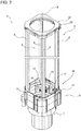
Figures 2 and3 is a perspective view, in enlarged scale and with parts removed for clarity, of a column of the cup dispenser ofFigure 1 in different operating conditions. -
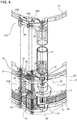
Figure 4 is a perspective view, on an enlarged scale and with parts in transparency and parts removed for clarity, of a detail of the column ofFigure 2 . -
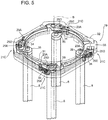
Figure 5 is a perspective, on an enlarged scale and with parts in transparency and parts removed for clarity of a further detail of the column ofFigure 2 . -
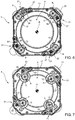
Figures 6 and 7 is cross-section, with parts removed for clarity, of the column ofFigure 2 in different operating conditions. -
Figures 8 and 9 are further cross-sections, with parts removed for clarity, of the column ofFigure 2 is the operating conditions shown inFigures 6 and 7 , respectively. - With reference to
Figure 1 ,reference numeral 1 globally denotes a cup dispenser (cups are visible inFigures 8 and 9 ), which is part of a beverage vending machine (known and not shown), for example a vending machine operable to dispense hot beverages prepared from an anhydrous material, such as tea, coffee, chocolate or the like. - In the beverage vending machines, the
cup dispenser 1 is operated at the beginning of a beverage preparation cycle to supply an empty cup to a cup filling station (not shown), in which the cup is filled with ingredients of a beverage recipe or with the beverage. - The
cup dispenser 1 comprises acup storage 2, in particular in the form of a turret, rotatably mounted within the beverage dispenser (in a known way and not described in detail) to rotate about a rotation axis A and comprising a support basket 3 (partially visible inFigure 1 ) and a plurality of cup containment and release members mounted on thebasket 3 around the axis A. - In particular, the cup containment and release members are defined by a plurality of
columns 4, which are releasably coupled to thebasket 3, and are each adapted to house a respective stack of cups, of the same size as or different from the cups housed in theother columns 4, and, during operation, are rotated by thebasket 3 about the axis A so as to selectively reach a stationary cup release station, which may correspond to the aforementioned cup filling station or be connected to the latter by means of a stationary chute adapted to rapidly convey to the cup filling station an empty cup released in the cup release station. - Since the
columns 4 are all structurally and functionally similar to each other, for brevity and ease of description, reference will be made hereinafter to asingle column 4. - In detail, as shown in
Figures 2 and3 , eachcolumn 4 has a longitudinal axis B parallel to the axis A, in assembling conditions, and includes: - a
containment portion 5, which defines an upper portion of thecolumn 4 and comprises a given number of containment members arranged around the axis B in such a way as to define therebetween aguide channel 6 adapted to laterally contain, preferably with a certain radial clearance, a respective stack of cups, and to axially guide the stack of cups as the cups are axially singled out from the bottom of the stack of cups; - an outlet or dispensing
portion 7, which defines a lower end portion ofcolumn 4 and preferably comprises a tubular chute along which individual cups, after being singled out from the respective stack of cups, fall downwards to reach a support device (not shown) defining the aforementioned cup filling station; and - an intermediate or
release portion 9, which is arranged between thecontainment portion 5 and theoutlet portion 7 and comprises acup release device 10 adapted to support the stack of cups contained in thecolumn 4 and, when operated, single out individual cups from the bottom of the stack of cups. - In the embodiment described herein, the aforementioned containment members that delimit the
guide channel 6 of thecontainment portion 5 are defined by a plurality ofrods 8 uniformly distributed around, and parallel to, the respective axis B. - In a variant not shown, the containment members may have the form of blades or other elongated members, more or less wide, and suitable to define the
guide channel 6. - In the example shown, thee
rods 8 are in the number of four but may be in any number, from a minimum of three. - The
rods 8 are coupled to theintermediate portion 9 at lower axial ends thereof and are mutually connected at their upper free axial ends by an annular joining members, which will be described hereinafter. - Preferably, each
column 4 further has a tubular casing (not shown), which surrounds therespective rods 8 so as to externally close theguide channel 6 and protect the stack of cups from exposure to external agents such as dust or moisture. - Conveniently, as shown in
Figures 2 ,3 and4 , thecup release device 10 is of a cam type and comprises a stationary annular body 11 (Figures 4 ,6 and 7 ) coaxial to the axis B and a plurality ofcam members 12, four in the example shown, mounted inside theannular body 11 to rotate about respective axes parallel to the axis B and evenly distributed about the axis B so as to define therebetween a cup downfall channel. - In detail, the
cam members 12 have a winding profile (of a known type) shaped to define, when thecam members 12 are at rest, a flat support for an edge of the last cup in the stack of cups so as to support the entire stack of cups. By contrast, when thecam members 12 are simultaneously rotated about their respective axes, the winding profiles insert between edges of the last and penultimate cups in the stack of cups so as to single out, and, hence, cause it to fall, the last cup in the stack of cups and, at the same time, support the remaining cups in the stack of cups. - In order to operate the cam members12, the
cup release device 10 has a transmission, preferably a gear transmission, adapted to be operated by an actuator assembly 13 (Figure 1 ) common to all thecup release devices 10 and arranged below thecup storage 2. - Conveniently, in the preferred embodiment shown in the appended Figures, the
actuator assembly 13 is configured to operate thecup release devices 10 when they reach the cup release station, and to rotate thecup storage 2 about the axis A in order to selectively bring thecolumns 4 to the cup release station. This type of actuator is described in detail inWO 2017/158345 , the contents of which are incorporated herein by reference. - In particular, as shown in
Figure 4 , eachcam member 12 comprises acylindrical toothed portion 15 meshing with arespective gear 16 mounted on theannular body 11 to rotate about a respective fixed axis parallel to axis B. Allgears 16 of thecam members 12 further mesh with aring gear 17 rotatably mounted about the axis B within theannular body 11. - One of the
gears 16, hereinafter referred to as 16a for clarity (Figures 8 and 9 ), also meshes with apower input gear 18 kinematically connected to theactuator assembly 13 to receive therefrom the power to be transmitted to thecup release device 10 to move it. - During operation, a rotation of the
power input gear 18 is transmitted from thegear 16a to thering gear 17, which, via theother gears 16, causes thecam members 12 to rotate simultaneously (Figures 8 and 9 ). - In the embodiment shown in the appended figures, the
cup release device 10 is of a radially adjustable type, i.e., the position of thecam members 12 of thecup release device 10 may be radially adjusted so as to increase or decrease the width of the cross-section of the cup downfall channel defined by thecam members 12. - In particular, the
cam members 12 are radially movable from and to the axis B to assume: - a retracted position, in which the cup downfall channel defined by the
cam members 12 has an enlarged cross-section and in which thecam members 12 are configured to support a first type of cups, in particular cups of relatively large size (diameter) (Figures 2 and6 ); and - an extracted position, in which the
cam members 12 are closer to axis B than in the retracted position, so as to define a cup downfall channel with a restricted cross-section and to support a second type of cups, in particular cups of a smaller size (diameter) than in the previous case (Figures 3 and7 ). - In a preferred embodiment, the
cam members 12 are movable in a plurality of stable intermediate positions, radially between the retracted and extracted positions. - In the present invention, the containment members, in this case the
rods 8, are radially movable from and to the axis B. - In other words, the
rods 8 are adjustable in a radial direction so as to narrow or widen the cross-section of theguide channel 6 and cause it to have a cross-section equal to, or at least comparable to, the section of the cup downfall channel defined by thecam members 12 and proportionate to the diameter of the cups in the stack of cups it houses, so as to perform an effective lateral containment and axial guidance of the stack of cups. In particular, therods 8 are radially movable at least between: - a maximum opening position, in which the
guide channel 6 has an enlarged cross-section (Figures 2 and6 ) to house a first type of cups, in particular cups of relatively large size (diameter); and - a minimum opening position, in which the
guide channel 6 has a smaller cross-section than in the previous case, to house a second type of cups, in particular cups of a smaller size (diameter) than in the previous case (Figures 3 and7 ). - Each
column 4 is thereby reconfigurable in size to accommodate different types of cups, particularly cups of different sizes. - In a preferred embodiment, the
rods 8 are movable in a plurality of stable intermediate positions, radially comprised between the minimum and maximum opening positions. - The
column 4 comprises anadjustment device 19 configured to adjust, i.e., to move, therods 8 between the minimum and maximum opening positions and, preferably, to arrange therods 8 in the above-mentioned radially intermediate positions. - In detail, the
adjustment device 19 comprises (Figure 4 ): - an
adjustment ring 20 rotatably mounted on theannular body 11 and coaxial to the axis B; - one or
more lever mechanisms 21, four in this case, i.e., one for eachrod 8, each of which is operatively coupled both to theadjustment ring 20 and to therespective rod 8, is arranged at theintermediate portion 9, and is operable to control the movement of therespective rod 8 between the minimum and maximum opening positions, or to one of the aforesaid stable intermediate positions; and - an
adjustment lever 22 angularly coupled to theadjustment ring 20 to operate, by means of the latter, thelever mechanisms 21 and cause the movement of therods 8. - In the example shown, the
adjustment lever 22 is defined by a switch mounted outside theannular body 11 and manually operable; in an alternative embodiment not shown, theadjustment lever 22 is replaced by a suitable powered control member, which is automatically operable based on the size of the cups incolumn 4. - In greater detail, each
lever mechanism 21 comprises (Figure 4 ): - a
pin 23 parallel to the axis B and integral with theadjustment ring 20 in a position angularly spaced from the correspondingrod 8; - a connecting
rod 24 hinged, at one first end, to thepin 23; and - a
rocker arm 26 hinged to apin 25A fixed on theannular body 11 and parallel to the axis B. Therocker arm 26 has two opposite arms, a first arm of which is hinged to a second end of the above-mentioned connectingrod 24 by means of apin 25B (Figure 4 ) parallel to thepin 25A, and a second arm of which is integral with therespective rod 8, at a lower end thereof. - During operation, the operation (displacement) of the
adjustment lever 22 causes an angular movement of theadjustment ring 20 about the axis B. This results in a corresponding rotation, about the axis B, of thepin 23 and of the connectingrod 24 which, pushed by thepin 23, rotates around the axis B and, at the same time, translates towards therespective rod 8. Thepin 25B, which rotatably connects the connectingrod 24 to the first arm of therocker arm 26, is arranged with respect to thefulcrum pin 25A of therocker arm 26 in such a position that the thrust given to the first arm by the connectingrod 24 causes therocker arm 26 to rotate about thefulcrum pin 25A in one direction or the other, depending on the direction of displacement of the connectingrod 24, which in turn depends on the direction of rotation of theadjustment ring 20. - Depending on the direction of rotation of the
rocker arm 26, the second arm of therocker arm 26 is moved closer to or further away from the axis B and, as a result, therelative rod 8 is moved between the minimum and maximum opening positions (Figures 6 and 7 ). This applies to eachlever mechanism 21 and to eachrod 8, since the movement of theadjustment ring 20 operates all thelever mechanisms 21 simultaneously. - In order to delimit the angular displacement of each
pin 23, thecolumn 4 comprises, for eachpin 23, a respective mechanical block. - In particular, each mechanical block is defined by a
slot 27 which is formed on theannular body 11, is in the form of an arc of a circle coaxial to the axis B, and is crosswise engaged by the correspondingpin 23. When pins 23 are moved along their respective slots as a result of a rotation of theadjustment ring 20, the closed ends of the slots constitute respective end stops for thepins 23, thus defining the minimum and maximum opening positions of therods 8 kinematically connected to thepins 23 by the respective connectingrods 24 androcker arms 26. - The above-described
adjustment device 19 may be used to adjust only the radial position of therods 8 or, in the preferred and non-limiting embodiment shown in the appended figures, theaforementioned adjustment device 19 is also configured to adjust the angular position of thecam members 12 between the above-mentioned retracted and extracted positions. - To this end, the
adjustment device 19 comprises: - a
further adjustment ring 28, which substantially corresponds to theadjustment ring 20, is rotatably mounted on theannular body 11 below, and at a certain distance from, theadjustment ring 20, and is operatively coupled to theadjustment lever 22; and - one or more
further lever mechanisms 21B, four in this case, i.e., one for each cam memberl2, functionally similar to thelever mechanisms 21, and configured to operatively couple theadjustment ring 28 to thecam members 12 so as to simultaneously move the latter between the respective retracted positions, extracted positions and intermediate stable positions in response to a rotation of theadjustment ring 28. - In particular, each
lever mechanism 21B comprises: - a connecting
rod 29, which is functionally similar to the connectingrod 24 and, like the latter, is hinged at a first end thereof, on thepin 23, which extends between, and mutually connects, theadjustment ring 20 and theadjustment ring 28; - a
rocker arm 30, which is functionally similar to therocker arm 26 and, like the latter, is hinged to thepin 25A, the axis of which matches with the axis of rotation of acorresponding gear 16. - Furthermore, similarly to the
rocker arm 26, therocker arm 30 also comprises two opposite arms, a first arm of which is hinged to a second end of the connectingrod 29 by means of apin 25C (Figure 4 ) coaxial to thepin 25A, and a second arm rotatably supports thecam members 12 whosetoothed portion 15 meshes with thegear 16. - In particular, as shown in
Figure 4 , the axis of rotation of thecam member 12 carried by arocker arm 30 and the axis of therod 8 carried by therocker arm 26 hinged to thesame pin 25A of therocker arm 30 are coincident and, preferably, thecam member 12 and thecorresponding rod 8 are mutually coupled via a connectingpin 36. - During operation, the operation (displacement) of the
adjustment lever 22 also causes, in addition to the rotation of theadjustment ring 20, an identical rotation of theadjustment ring 28 about the axis B. Similarly to what described above with reference to the connectingrod 24 and therocker arm 26, the angular displacement of theadjustment ring 28 results in a rotation about thepin 25A of therocker arm 30 and, therefore, of the correspondingcam member 12. - Depending on the direction of rotation of
rocker arm 30, rotation of the latter results in the second arm of therocker arm 30 being moved closer to or away from the axis B and, consequently, in thecam member 12 being moved between the retracted and extracted positions (Figures 6 and 7 ). - This applies simultaneously to each
lever mechanism 21B and eachcam member 12, since theadjustment ring 28 operates all thelever mechanisms 21B simultaneously. - The fact that the adjustment rings 20 and 28 are mutually connected by
pins 23 and thecam members 12 are integrally connected to the correspondingrods 8 by the corresponding pins 36 results in a synchronised adjustment of therods 8 and ofcam members 12. - A radial movement of the
cam member 12 thereby corresponds to a radial movement of thecorresponding rod 8, resulting in a synchronous adjustment of theguide channel 6 and the cup downfall channel. - In view of the above, the
adjustment lever 22 can be moved between: - a first position, in which the
rods 8 are in their maximum opening positions and thecam members 12 are in their retracted positions (Figures 2 and6 ); and - a second position, in which the
rods 8 are in their minimum opening positions and thecam members 12 are in their extracted positions (Figures 3 and7 ). - In an alternative embodiment not shown, the above-described
adjustment device 19 is, relative to therods 8, operatively independent from thecam members 12 in the sense that the radial adjustment of the latter is carried out independently of the adjustment of therods 8 by means of a further adjustment device of the same type as or different from that which adjusts therods 8. - In the preferred embodiment shown in the accompanying figures, to further improve the control and precision of radial adjustment of the
rods 8, theadjustment device 19 is further configured to provide the same radial displacement to the upper ends of therods 8 as theadjustment ring 20 provides to the lower ends of therods 8. - To this end, the
adjustment device 19 comprises (Figures 4 and5 ): - a
further adjustment ring 31, which is part of the above-mentioned annular joint mutually connecting the upper free ends of therods 8, is rotatably mounted about the axis B on a stationary upperannular body 32 of the column 4 (Figures 1 ,2 ,3 and5 ), and substantially corresponds to, and is aligned with, the adjustment rings 20 and 28; - one or more
further lever mechanisms 21C, four in this case, i.e., one for eachrod 8, functionally similar to thelever mechanisms adjustment ring 31 to therods 8 so as to simultaneously move the upper ends of the latter between their respective minimum and maximum opening positions in response to a rotation of theadjustment ring 31; and - an
adjustment lever 33 integral with theadjustment ring 31 and movable to operate, via theadjustment ring 31, thelever mechanisms 21C and cause therods 8 to move. - In the example shown, the
adjustment lever 33 is defined by a manually operable switch which is functionally similar to the switch defined by theadjustment lever 22; in an alternative embodiment not shown, theadjustment lever 33 may be replaced by a suitable powered control member, which may be operated automatically depending on the size of the cups incolumn 4. - In particular, each
lever mechanism 21C comprises: - a connecting
rod 34, which is functionally similar to the connectingrods pin 23A integrally fixed to theadjustment ring 31 and coaxial to thepin 23; and - a
rocker arm 35, which is functionally similar to therocker arms pin 25D aligned with thepin 25A. - Similarly to the
rocker arms rocker arm 35 also comprises two opposite arms, a first arm of which is hinged to a second end of the connectingrod 34 by means of apin 25E (Figure 4 ) parallel to thepin 25A and aligned with thepins relative rod 8. - Operation of the
adjustment ring 31 and associatedlever mechanisms 21C is substantially identical to that of theadjustment ring 20 andrespective lever mechanisms 21 and to that of theadjustment ring 28 andrespective lever mechanisms 21B and will not be further detailed herein. - It should only be noted that, in order to achieve an even radial adjustment of the
guide channel 6, it is important that the adjustment rings 20 and 28 and theadjustment ring 31 are provided with the same angular displacement by means of theadjustment lever 22 andadjustment lever 33 respectively. In order to ensure that this movement is identical, it is possible to make theadjustment lever 22 and theadjustment lever 33 as a single adjustment lever adapted to simultaneously control the adjustment rings 20, 28 and 31. - Review of the features of the
cup dispenser 1 of the present invention allow the advantages that it allows to obtain to be appreciated. - In particular, the provision of radially
adjustable rods 8 allows to useguide channels 6 whose size - diameter - can be varied depending on manufacturing requirements. - In practice, each
column 4 made according to the invention can be adjusted to accommodate different types of cups. - The operative flexibility of the
cup dispenser 1 is therefore improved if compared to the case where the columns do not have an adjustable guide channel.
Claims (12)
- A cup dispenser (1) for a beverage vending machine; the cup dispenser (1) comprises at least a cup containment and release assembly (4) with a longitudinal axis (B) and comprising:- a containment portion (5), which defines a guide channel (6) coaxial with the longitudinal axis (B) and adapted to contain a stack of cups; and- a release portion (9), which is arranged below the containment portion (5) and is configured to support the stack of cups and single out individual cups from the bottom of the stack of cups;the containment portion (5) comprises a number of containment members (8) laterally delimiting the guide channel (6);characterized in that the containment members (8) are mounted to be radially movable to modify a cross section of the guide channel (6).
- The cup dispenser (1) of claim 1, wherein the containment members (8) are radially moveable between:- a maximum opening position, in which the guide channel (6) is so sized as to contain larger cups; and- a minimum opening position, in which the guide channel (6) is so sized as to contain smaller cups;
and wherein the cup containment and release assembly (4) comprises an adjustment device (19) configured to simultaneously move all the containment members (8) between the maximum and minimum opening positions. - The cup dispenser (1) of claim 2, wherein the adjustment device (19) comprises a first adjustment ring (20) mounted to rotate about the longitudinal axis (B), and a number of first lever mechanisms (21), each of which kinematically connects the first adjustment ring (20) and a corresponding containment member (8) to move the containment member (8) between the maximum and minimum opening positions in response to a rotation of the first adjustment ring (20) about the longitudinal axis (B).
- The cup dispenser (1) of claim 3, wherein each first lever mechanism (21) comprises:- a movable pin (23) fixed to the first adjustment ring (20) to rotate therewith about the longitudinal axis (B);- a connecting rod (24) with a first end hinged to the movable pin (23); and- a rocker arm (26) hinged to a fixed fulcrum pin (25A) and comprising a first arm hinged to a second end of the connecting rod (24), and a second arm rigidly connected to the corresponding containment member (8) to cause a rotation of the rocker arm (26) about the fulcrum pin (25A) to result in a radial movement of the containment member (8) from or towards the maximum opening position or the minimum opening position.
- The cup dispenser (1) of claim 3 or 4, wherein the first adjustment ring (20) and the first lever mechanisms (21) are arranged at a lower axial end of the containment members (8).
- The cup dispenser (1) of claim 5, wherein the adjustment device (19) further comprises a second adjustment ring (31) and a number of second lever mechanisms (21C), which are functionally equivalent to the first adjustment ring (20) and, respectively, to the first lever mechanisms (21), and are arranged at an upper axial end of the containment members (8).
- The cup dispenser (1) of any one of the preceding claims, wherein the release portion (9) comprises a release device (10) with a number of release members (12), which define a cup downfall channel and are configured to support the stack of cups and to single out individual cups from the bottom of the stack;the release members (12) are radially moveable between:- a retracted position, in which the cup downfall channel is configured to support and release larger cups; and- an extracted position, in which the cup downfall channel is configured to support and release smaller cups;wherein the adjustment device (19) is further configured to simultaneously move all the release members (12) between the retracted and extracted positions to modify a cross section of the cup downfall channel.
- The cup dispenser (1) of claim 7, wherein, in order to radially adjust the position of the release members (12), the adjustment device (19) comprises a third adjustment ring (28) and a number of third lever mechanisms (21B), which are functionally equivalent to the first adjustment ring (20) and, respectively, to the first lever mechanisms (21) and are arranged at the release members (12).
- The cup dispenser (1) of claim 8, wherein each third lever mechanism (21B) comprises:- a movable pin (23) fixed to the third adjustment ring (28) to rotate therewith about the longitudinal axis (B);- a connecting rod (29) with a first end hinged to the movable pin (23); and- a rocker arm (30) hinged to a fixed fulcrum pin (25A) and comprising a first arm hinged to a second end of the connecting rod (29), and a second arm rigidly connected to a corresponding release member (12) to cause a rotation of the rocker arm (30) about the fulcrum pin (25A) to result in a radial movement of the release member (12) from or towards the retracted position or the extracted position.
- The cup dispenser (1) of claim 8 or 9, wherein the first adjustment ring (20) and the third adjustment ring (28) are mutually angularly coupled so that a radial movement of the containment members (8) corresponds to the same radial movement of the release members (12).
- The cup dispenser (1) of any one of the preceding claims, wherein the containment members (8) are in the form of rods or longitudinal blades parallel to the longitudinal axis (B) and delimiting the guide channel (6).
- The cup dispenser (1) of any one of the preceding claims, wherein the cup dispenser (1) is of a turret type and further comprises:- a support (3) mounted to rotate about a rotation axis (A);- a plurality of cup containment and release members (4) mounted on the support (3) around the rotation axis (A) with respective longitudinal axes (B) parallel to the rotation axis (A); and- an actuator (13) operable to rotate the support (3) about the rotation axis (A) and selectively move the cup containment and release members (4) to a stationary cup release station.
Applications Claiming Priority (1)
| Application Number | Priority Date | Filing Date | Title |
|---|---|---|---|
| IT102020000016861A IT202000016861A1 (en) | 2020-07-10 | 2020-07-10 | GLASS DISPENSER FOR A DRINK VENDING MACHINE |
Publications (2)
| Publication Number | Publication Date |
|---|---|
| EP3937142A1 true EP3937142A1 (en) | 2022-01-12 |
| EP3937142B1 EP3937142B1 (en) | 2023-08-30 |
Family
ID=72561887
Family Applications (1)
| Application Number | Title | Priority Date | Filing Date |
|---|---|---|---|
| EP21184901.3A Active EP3937142B1 (en) | 2020-07-10 | 2021-07-09 | Cup dispenser for a beverage vending machine |
Country Status (3)
| Country | Link |
|---|---|
| EP (1) | EP3937142B1 (en) |
| ES (1) | ES2959973T3 (en) |
| IT (1) | IT202000016861A1 (en) |
Citations (4)
| Publication number | Priority date | Publication date | Assignee | Title |
|---|---|---|---|---|
| US5518149A (en) * | 1994-07-28 | 1996-05-21 | Gross-Given Manufacturing Company | Cup dispenser for vending machines |
| EP1575006A1 (en) * | 2004-03-05 | 2005-09-14 | F.A.S. International S.p.A. | Cup feeder |
| WO2017158345A1 (en) | 2016-03-16 | 2017-09-21 | Xaar Technology Limited | A piezoelectric thin film element |
| EP3576056A1 (en) * | 2018-06-01 | 2019-12-04 | Bianchi Industry S.p.a. | Device for dispensing cups and the like |
Family Cites Families (1)
| Publication number | Priority date | Publication date | Assignee | Title |
|---|---|---|---|---|
| US3057515A (en) * | 1961-05-17 | 1962-10-09 | Paper Machinery Corp | Cup feeder |
-
2020
- 2020-07-10 IT IT102020000016861A patent/IT202000016861A1/en unknown
-
2021
- 2021-07-09 EP EP21184901.3A patent/EP3937142B1/en active Active
- 2021-07-09 ES ES21184901T patent/ES2959973T3/en active Active
Patent Citations (4)
| Publication number | Priority date | Publication date | Assignee | Title |
|---|---|---|---|---|
| US5518149A (en) * | 1994-07-28 | 1996-05-21 | Gross-Given Manufacturing Company | Cup dispenser for vending machines |
| EP1575006A1 (en) * | 2004-03-05 | 2005-09-14 | F.A.S. International S.p.A. | Cup feeder |
| WO2017158345A1 (en) | 2016-03-16 | 2017-09-21 | Xaar Technology Limited | A piezoelectric thin film element |
| EP3576056A1 (en) * | 2018-06-01 | 2019-12-04 | Bianchi Industry S.p.a. | Device for dispensing cups and the like |
Also Published As
| Publication number | Publication date |
|---|---|
| ES2959973T3 (en) | 2024-02-29 |
| EP3937142B1 (en) | 2023-08-30 |
| IT202000016861A1 (en) | 2022-01-10 |
Similar Documents
| Publication | Publication Date | Title |
|---|---|---|
| CN109155095B (en) | Cup dispenser for beverage vending machine | |
| CN108968687B (en) | Dosing device and dosing method for a filter holder of an espresso coffee machine | |
| ITBO20090295A1 (en) | MACHINE FOR FILLING CAPSULES WITH PHARMACEUTICALS | |
| EP3997678A1 (en) | A cup dispenser for a beverage vending machine | |
| GB2148839A (en) | Product capsuling process and plant, particularly for pharmaceutical products | |
| US20130105277A1 (en) | Drug Sorting Device | |
| EP3937142B1 (en) | Cup dispenser for a beverage vending machine | |
| US3350835A (en) | Coin counting and wrapping device | |
| CS218588B2 (en) | Facility for grouping the products of the flat form in the sets | |
| US11974693B2 (en) | Brewing device for a beverage preparation machine, in particular coffee or tea | |
| US4469242A (en) | Delivery mechanism for a vending machine | |
| CN109035598B (en) | Equipment is sold in noodless system | |
| EP4380882B1 (en) | Strip feeding apparatus, in particular for a stirrer dispenser in a beverage vending machine | |
| GB2090821A (en) | Vending apparatus | |
| US3311260A (en) | Cup dispensing apparatus | |
| WO2023112065A1 (en) | Apparatus and method for packaging packets of smoking articles grouped into several organized groups | |
| JPH07323075A (en) | Powder medicine posing apparatus | |
| RU2803484C2 (en) | Glass dispenser for beverage vending machine | |
| WO1995011658A1 (en) | Method and device for filling one or more capsules with powder | |
| EP3846140B1 (en) | Discharging mechanism, material storing device, and self-service vending machine | |
| JP2646165B2 (en) | Powder supply device | |
| KR970003927B1 (en) | Rice metering device | |
| IT201900007287A1 (en) | AUTOMATIC DISTRIBUTOR OF DISHES AND METHOD FOR COOKING THE DISHES | |
| ITPN20010044A1 (en) | AUTOMATIC SPIRAL DISPENSER FOR PACKED PRODUCTS | |
| JPH07313577A (en) | Powdered medicine separately packing machine |
Legal Events
| Date | Code | Title | Description |
|---|---|---|---|
| PUAI | Public reference made under article 153(3) epc to a published international application that has entered the european phase |
Free format text: ORIGINAL CODE: 0009012 |
|
| STAA | Information on the status of an ep patent application or granted ep patent |
Free format text: STATUS: THE APPLICATION HAS BEEN PUBLISHED |
|
| AK | Designated contracting states |
Kind code of ref document: A1 Designated state(s): AL AT BE BG CH CY CZ DE DK EE ES FI FR GB GR HR HU IE IS IT LI LT LU LV MC MK MT NL NO PL PT RO RS SE SI SK SM TR |
|
| B565 | Issuance of search results under rule 164(2) epc |
Effective date: 20211201 |
|
| STAA | Information on the status of an ep patent application or granted ep patent |
Free format text: STATUS: REQUEST FOR EXAMINATION WAS MADE |
|
| 17P | Request for examination filed |
Effective date: 20220712 |
|
| RBV | Designated contracting states (corrected) |
Designated state(s): AL AT BE BG CH CY CZ DE DK EE ES FI FR GB GR HR HU IE IS IT LI LT LU LV MC MK MT NL NO PL PT RO RS SE SI SK SM TR |
|
| RAP3 | Party data changed (applicant data changed or rights of an application transferred) |
Owner name: EVOCA S.P.A. |
|
| STAA | Information on the status of an ep patent application or granted ep patent |
Free format text: STATUS: EXAMINATION IS IN PROGRESS |
|
| 17Q | First examination report despatched |
Effective date: 20221017 |
|
| GRAP | Despatch of communication of intention to grant a patent |
Free format text: ORIGINAL CODE: EPIDOSNIGR1 |
|
| STAA | Information on the status of an ep patent application or granted ep patent |
Free format text: STATUS: GRANT OF PATENT IS INTENDED |
|
| INTG | Intention to grant announced |
Effective date: 20230206 |
|
| GRAS | Grant fee paid |
Free format text: ORIGINAL CODE: EPIDOSNIGR3 |
|
| P01 | Opt-out of the competence of the unified patent court (upc) registered |
Effective date: 20230530 |
|
| GRAA | (expected) grant |
Free format text: ORIGINAL CODE: 0009210 |
|
| STAA | Information on the status of an ep patent application or granted ep patent |
Free format text: STATUS: THE PATENT HAS BEEN GRANTED |
|
| AK | Designated contracting states |
Kind code of ref document: B1 Designated state(s): AL AT BE BG CH CY CZ DE DK EE ES FI FR GB GR HR HU IE IS IT LI LT LU LV MC MK MT NL NO PL PT RO RS SE SI SK SM TR |
|
| REG | Reference to a national code |
Ref country code: GB Ref legal event code: FG4D |
|
| REG | Reference to a national code |
Ref country code: CH Ref legal event code: EP |
|
| REG | Reference to a national code |
Ref country code: NL Ref legal event code: FP |
|
| REG | Reference to a national code |
Ref country code: DE Ref legal event code: R096 Ref document number: 602021004650 Country of ref document: DE |
|
| REG | Reference to a national code |
Ref country code: IE Ref legal event code: FG4D |
|
| REG | Reference to a national code |
Ref country code: SE Ref legal event code: TRGR |
|
| REG | Reference to a national code |
Ref country code: LT Ref legal event code: MG9D |
|
| REG | Reference to a national code |
Ref country code: AT Ref legal event code: MK05 Ref document number: 1606444 Country of ref document: AT Kind code of ref document: T Effective date: 20230830 |
|
| PG25 | Lapsed in a contracting state [announced via postgrant information from national office to epo] |
Ref country code: GR Free format text: LAPSE BECAUSE OF FAILURE TO SUBMIT A TRANSLATION OF THE DESCRIPTION OR TO PAY THE FEE WITHIN THE PRESCRIBED TIME-LIMIT Effective date: 20231201 |
|
| PG25 | Lapsed in a contracting state [announced via postgrant information from national office to epo] |
Ref country code: IS Free format text: LAPSE BECAUSE OF FAILURE TO SUBMIT A TRANSLATION OF THE DESCRIPTION OR TO PAY THE FEE WITHIN THE PRESCRIBED TIME-LIMIT Effective date: 20231230 |
|
| PG25 | Lapsed in a contracting state [announced via postgrant information from national office to epo] |
Ref country code: RS Free format text: LAPSE BECAUSE OF FAILURE TO SUBMIT A TRANSLATION OF THE DESCRIPTION OR TO PAY THE FEE WITHIN THE PRESCRIBED TIME-LIMIT Effective date: 20230830 Ref country code: NO Free format text: LAPSE BECAUSE OF FAILURE TO SUBMIT A TRANSLATION OF THE DESCRIPTION OR TO PAY THE FEE WITHIN THE PRESCRIBED TIME-LIMIT Effective date: 20231130 Ref country code: LV Free format text: LAPSE BECAUSE OF FAILURE TO SUBMIT A TRANSLATION OF THE DESCRIPTION OR TO PAY THE FEE WITHIN THE PRESCRIBED TIME-LIMIT Effective date: 20230830 Ref country code: LT Free format text: LAPSE BECAUSE OF FAILURE TO SUBMIT A TRANSLATION OF THE DESCRIPTION OR TO PAY THE FEE WITHIN THE PRESCRIBED TIME-LIMIT Effective date: 20230830 Ref country code: IS Free format text: LAPSE BECAUSE OF FAILURE TO SUBMIT A TRANSLATION OF THE DESCRIPTION OR TO PAY THE FEE WITHIN THE PRESCRIBED TIME-LIMIT Effective date: 20231230 Ref country code: HR Free format text: LAPSE BECAUSE OF FAILURE TO SUBMIT A TRANSLATION OF THE DESCRIPTION OR TO PAY THE FEE WITHIN THE PRESCRIBED TIME-LIMIT Effective date: 20230830 Ref country code: GR Free format text: LAPSE BECAUSE OF FAILURE TO SUBMIT A TRANSLATION OF THE DESCRIPTION OR TO PAY THE FEE WITHIN THE PRESCRIBED TIME-LIMIT Effective date: 20231201 Ref country code: FI Free format text: LAPSE BECAUSE OF FAILURE TO SUBMIT A TRANSLATION OF THE DESCRIPTION OR TO PAY THE FEE WITHIN THE PRESCRIBED TIME-LIMIT Effective date: 20230830 Ref country code: AT Free format text: LAPSE BECAUSE OF FAILURE TO SUBMIT A TRANSLATION OF THE DESCRIPTION OR TO PAY THE FEE WITHIN THE PRESCRIBED TIME-LIMIT Effective date: 20230830 |
|
| PG25 | Lapsed in a contracting state [announced via postgrant information from national office to epo] |
Ref country code: PL Free format text: LAPSE BECAUSE OF FAILURE TO SUBMIT A TRANSLATION OF THE DESCRIPTION OR TO PAY THE FEE WITHIN THE PRESCRIBED TIME-LIMIT Effective date: 20230830 |
|
| REG | Reference to a national code |
Ref country code: ES Ref legal event code: FG2A Ref document number: 2959973 Country of ref document: ES Kind code of ref document: T3 Effective date: 20240229 |
|
| PG25 | Lapsed in a contracting state [announced via postgrant information from national office to epo] |
Ref country code: SM Free format text: LAPSE BECAUSE OF FAILURE TO SUBMIT A TRANSLATION OF THE DESCRIPTION OR TO PAY THE FEE WITHIN THE PRESCRIBED TIME-LIMIT Effective date: 20230830 Ref country code: RO Free format text: LAPSE BECAUSE OF FAILURE TO SUBMIT A TRANSLATION OF THE DESCRIPTION OR TO PAY THE FEE WITHIN THE PRESCRIBED TIME-LIMIT Effective date: 20230830 Ref country code: EE Free format text: LAPSE BECAUSE OF FAILURE TO SUBMIT A TRANSLATION OF THE DESCRIPTION OR TO PAY THE FEE WITHIN THE PRESCRIBED TIME-LIMIT Effective date: 20230830 Ref country code: DK Free format text: LAPSE BECAUSE OF FAILURE TO SUBMIT A TRANSLATION OF THE DESCRIPTION OR TO PAY THE FEE WITHIN THE PRESCRIBED TIME-LIMIT Effective date: 20230830 Ref country code: CZ Free format text: LAPSE BECAUSE OF FAILURE TO SUBMIT A TRANSLATION OF THE DESCRIPTION OR TO PAY THE FEE WITHIN THE PRESCRIBED TIME-LIMIT Effective date: 20230830 Ref country code: SK Free format text: LAPSE BECAUSE OF FAILURE TO SUBMIT A TRANSLATION OF THE DESCRIPTION OR TO PAY THE FEE WITHIN THE PRESCRIBED TIME-LIMIT Effective date: 20230830 Ref country code: PT Free format text: LAPSE BECAUSE OF FAILURE TO SUBMIT A TRANSLATION OF THE DESCRIPTION OR TO PAY THE FEE WITHIN THE PRESCRIBED TIME-LIMIT Effective date: 20240102 |
|
| REG | Reference to a national code |
Ref country code: DE Ref legal event code: R097 Ref document number: 602021004650 Country of ref document: DE |
|
| PLBE | No opposition filed within time limit |
Free format text: ORIGINAL CODE: 0009261 |
|
| STAA | Information on the status of an ep patent application or granted ep patent |
Free format text: STATUS: NO OPPOSITION FILED WITHIN TIME LIMIT |
|
| PG25 | Lapsed in a contracting state [announced via postgrant information from national office to epo] |
Ref country code: SI Free format text: LAPSE BECAUSE OF FAILURE TO SUBMIT A TRANSLATION OF THE DESCRIPTION OR TO PAY THE FEE WITHIN THE PRESCRIBED TIME-LIMIT Effective date: 20230830 |
|
| 26N | No opposition filed |
Effective date: 20240603 |
|
| PGFP | Annual fee paid to national office [announced via postgrant information from national office to epo] |
Ref country code: NL Payment date: 20240725 Year of fee payment: 4 |
|
| PGFP | Annual fee paid to national office [announced via postgrant information from national office to epo] |
Ref country code: DE Payment date: 20240730 Year of fee payment: 4 |
|
| PGFP | Annual fee paid to national office [announced via postgrant information from national office to epo] |
Ref country code: SE Payment date: 20240725 Year of fee payment: 4 |
|
| PG25 | Lapsed in a contracting state [announced via postgrant information from national office to epo] |
Ref country code: BG Free format text: LAPSE BECAUSE OF FAILURE TO SUBMIT A TRANSLATION OF THE DESCRIPTION OR TO PAY THE FEE WITHIN THE PRESCRIBED TIME-LIMIT Effective date: 20230830 |
|
| PG25 | Lapsed in a contracting state [announced via postgrant information from national office to epo] |
Ref country code: BG Free format text: LAPSE BECAUSE OF FAILURE TO SUBMIT A TRANSLATION OF THE DESCRIPTION OR TO PAY THE FEE WITHIN THE PRESCRIBED TIME-LIMIT Effective date: 20230830 |
|
| PG25 | Lapsed in a contracting state [announced via postgrant information from national office to epo] |
Ref country code: MC Free format text: LAPSE BECAUSE OF FAILURE TO SUBMIT A TRANSLATION OF THE DESCRIPTION OR TO PAY THE FEE WITHIN THE PRESCRIBED TIME-LIMIT Effective date: 20230830 |
|
| REG | Reference to a national code |
Ref country code: CH Ref legal event code: PL |
|
| PG25 | Lapsed in a contracting state [announced via postgrant information from national office to epo] |
Ref country code: LU Free format text: LAPSE BECAUSE OF NON-PAYMENT OF DUE FEES Effective date: 20240709 |
|
| PG25 | Lapsed in a contracting state [announced via postgrant information from national office to epo] |
Ref country code: LU Free format text: LAPSE BECAUSE OF NON-PAYMENT OF DUE FEES Effective date: 20240709 |
|
| PG25 | Lapsed in a contracting state [announced via postgrant information from national office to epo] |
Ref country code: CH Free format text: LAPSE BECAUSE OF NON-PAYMENT OF DUE FEES Effective date: 20240731 Ref country code: BE Free format text: LAPSE BECAUSE OF NON-PAYMENT OF DUE FEES Effective date: 20240731 |
|
| REG | Reference to a national code |
Ref country code: BE Ref legal event code: MM Effective date: 20240731 |
|
| PG25 | Lapsed in a contracting state [announced via postgrant information from national office to epo] |
Ref country code: IE Free format text: LAPSE BECAUSE OF NON-PAYMENT OF DUE FEES Effective date: 20240709 |
|
| PGFP | Annual fee paid to national office [announced via postgrant information from national office to epo] |
Ref country code: ES Payment date: 20250812 Year of fee payment: 5 |
|
| PGFP | Annual fee paid to national office [announced via postgrant information from national office to epo] |
Ref country code: IT Payment date: 20250702 Year of fee payment: 5 |
|
| PGFP | Annual fee paid to national office [announced via postgrant information from national office to epo] |
Ref country code: FR Payment date: 20250725 Year of fee payment: 5 |
|
| PG25 | Lapsed in a contracting state [announced via postgrant information from national office to epo] |
Ref country code: CY Free format text: LAPSE BECAUSE OF FAILURE TO SUBMIT A TRANSLATION OF THE DESCRIPTION OR TO PAY THE FEE WITHIN THE PRESCRIBED TIME-LIMIT; INVALID AB INITIO Effective date: 20210709 |
|
| REG | Reference to a national code |
Ref country code: DE Ref legal event code: R119 Ref document number: 602021004650 Country of ref document: DE |
|
| REG | Reference to a national code |
Ref country code: NL Ref legal event code: MM Effective date: 20250801 |
|
| PG25 | Lapsed in a contracting state [announced via postgrant information from national office to epo] |
Ref country code: HU Free format text: LAPSE BECAUSE OF FAILURE TO SUBMIT A TRANSLATION OF THE DESCRIPTION OR TO PAY THE FEE WITHIN THE PRESCRIBED TIME-LIMIT; INVALID AB INITIO Effective date: 20210709 |
|
| GBPC | Gb: european patent ceased through non-payment of renewal fee |
Effective date: 20250709 |
|
| PG25 | Lapsed in a contracting state [announced via postgrant information from national office to epo] |
Ref country code: GB Free format text: LAPSE BECAUSE OF NON-PAYMENT OF DUE FEES Effective date: 20250709 |
|
| PG25 | Lapsed in a contracting state [announced via postgrant information from national office to epo] |
Ref country code: DE Free format text: LAPSE BECAUSE OF NON-PAYMENT OF DUE FEES Effective date: 20260203 |
|
| PG25 | Lapsed in a contracting state [announced via postgrant information from national office to epo] |
Ref country code: NL Free format text: LAPSE BECAUSE OF NON-PAYMENT OF DUE FEES Effective date: 20250801 |